EP3312952B1 - Zündkerze - Google Patents
Zündkerze Download PDFInfo
- Publication number
- EP3312952B1 EP3312952B1 EP16813894.9A EP16813894A EP3312952B1 EP 3312952 B1 EP3312952 B1 EP 3312952B1 EP 16813894 A EP16813894 A EP 16813894A EP 3312952 B1 EP3312952 B1 EP 3312952B1
- Authority
- EP
- European Patent Office
- Prior art keywords
- seal body
- center electrode
- seal layer
- spark plug
- diameter portion
- Prior art date
- Legal status (The legal status is an assumption and is not a legal conclusion. Google has not performed a legal analysis and makes no representation as to the accuracy of the status listed.)
- Active
Links
Images



Classifications
-
- H—ELECTRICITY
- H01—ELECTRIC ELEMENTS
- H01T—SPARK GAPS; OVERVOLTAGE ARRESTERS USING SPARK GAPS; SPARKING PLUGS; CORONA DEVICES; GENERATING IONS TO BE INTRODUCED INTO NON-ENCLOSED GASES
- H01T13/00—Sparking plugs
- H01T13/20—Sparking plugs characterised by features of the electrodes or insulation
- H01T13/34—Sparking plugs characterised by features of the electrodes or insulation characterised by the mounting of electrodes in insulation, e.g. by embedding
-
- H—ELECTRICITY
- H01—ELECTRIC ELEMENTS
- H01T—SPARK GAPS; OVERVOLTAGE ARRESTERS USING SPARK GAPS; SPARKING PLUGS; CORONA DEVICES; GENERATING IONS TO BE INTRODUCED INTO NON-ENCLOSED GASES
- H01T13/00—Sparking plugs
- H01T13/20—Sparking plugs characterised by features of the electrodes or insulation
-
- H—ELECTRICITY
- H01—ELECTRIC ELEMENTS
- H01T—SPARK GAPS; OVERVOLTAGE ARRESTERS USING SPARK GAPS; SPARKING PLUGS; CORONA DEVICES; GENERATING IONS TO BE INTRODUCED INTO NON-ENCLOSED GASES
- H01T13/00—Sparking plugs
- H01T13/40—Sparking plugs structurally combined with other devices
- H01T13/41—Sparking plugs structurally combined with other devices with interference suppressing or shielding means
-
- H—ELECTRICITY
- H01—ELECTRIC ELEMENTS
- H01T—SPARK GAPS; OVERVOLTAGE ARRESTERS USING SPARK GAPS; SPARKING PLUGS; CORONA DEVICES; GENERATING IONS TO BE INTRODUCED INTO NON-ENCLOSED GASES
- H01T21/00—Apparatus or processes specially adapted for the manufacture or maintenance of spark gaps or sparking plugs
- H01T21/02—Apparatus or processes specially adapted for the manufacture or maintenance of spark gaps or sparking plugs of sparking plugs
Definitions
- the present invention relates to a spark plug.
- a spark plug is a component that generates spark discharge in order to ignite an air-fuel mixture in a combustion chamber.
- a structure of the spark plug there is known a structure that includes: a ceramic insulator in which an axial hole is provided so as to extend along an axis; a metal shell that holds the ceramic insulator therein; a center electrode held in the axial hole; and a conductive seal body for holding the center electrode in the axial hole (Patent Document 1).
- the center electrode includes a flange portion projecting in a radial direction, and a head portion protruding from the flange portion toward a rear end side, and by using this structure, the center electrode is held in the ceramic insulator.
- the center electrode is prevented from moving toward a front end side.
- the seal body being filled into a portion around the head portion and the flange portion, impact resistance of the center electrode is secured, whereby loosening of the center electrode is less likely to occur even when the center electrode is subjected to impact by combustion.
- the conductor is the seal body or the center electrode.
- the reduction of the electrostatic capacity is achieved by, for example, shortening the head portion and correspondingly reducing the height of the seal body in an axial direction.
- a holding force by the seal body may be lowered to reduce the impact resistance of the center electrode, whereby loosening of the center electrode is likely to occur.
- the present invention is made in view of the above situation, and an object of the present invention is to achieve both reduction of the electrostatic capacity and securing of the impact resistance of the center electrode.
- the present invention has been made to solve the above-described problem, and can be embodied in the following aspects.
- a spark plug which includes the features of appended claim 1.
- the insulating seal body may contact a forward facing surface of the conductive seal body. According to this aspect, the electrostatic capacity can be reduced by securing an area of contact with the ceramic insulator in a height direction.
- the insulating seal body may contain glass as a main component. According to this aspect, since the insulating seal body is favorably fixed at the portion in contact with the center electrode, the impact resistance is improved.
- the deviation can be prevented.
- FIG. 1 is a cross-sectional view of a spark plug 101.
- the spark plug 101 includes a metal shell 1, a ceramic insulator 2, a center electrode 3, a ground electrode 4, and a metal terminal 13.
- the center, in the longitudinal direction, of the spark plug 101 is represented as an axis O.
- the ground electrode 4 side is referred to as a front end side of the spark plug 101
- the metal terminal 13 side is referred to as a rear end side.
- the metal shell 1 is formed from a metal such as carbon steel into a hollow cylindrical shape to form a housing of the spark plug 101.
- the ceramic insulator 2 is formed from a ceramic sintered body, and a front end side thereof is housed in the metal shell 1.
- the ceramic insulator 2 is a cylindrical member, and an axial hole 6 is formed therein so as to extend along the axis O.
- a part of the metal terminal 13 is inserted and fixed into one of end portions of the axial hole 6, and the center electrode 3 is inserted and fixed into the other of the end portions thereof.
- a resistor 15 is arranged between the metal terminal 13 and the center electrode 3. Both end portions of the resistor 15 are electrically connected to the center electrode 3 and the metal terminal 13 via a seal layer 16 and a conductive glass seal layer 17, respectively, on a metal terminal side.
- the resistor 15 functions as an electric resistance between the metal terminal 13 and the center electrode 3 to suppress generation of radio interference noise (noise) during spark discharge.
- the resistor 15 includes ceramic powder, a conductive material, glass, and a binder (adhesive). In the present embodiment, the resistor 15 is manufactured through a manufacturing procedure described below.
- the center electrode 3 has a firing end 31 formed at a front end thereof, and is arranged in the axial hole 6 in a state where the firing end 31 is exposed.
- the ground electrode 4 is welded at one end thereof to the metal shell 1.
- the ground electrode 4 is arranged such that the other end portion of the ground electrode 4 is bent laterally and a front end portion 32 thereof opposes the firing end 31 of the center electrode 3 via a gap.
- a screw portion is formed on the outer periphery of the metal shell 1 of the spark plug 101 having the above-described structure.
- the spark plug 101 is mounted to a cylinder head of an engine by using the screw portion.
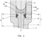
- FIG. 2 is an enlarged cross-sectional view of a portion near the seal layer 16.
- the axial hole 6 includes a large-diameter portion 6w and a small-diameter portion 6n.
- the large-diameter portion 6w is larger in inner diameter than the small-diameter portion 6n.
- the large-diameter portion 6w includes a stepped portion 6s, and is connected to a rear end of the small-diameter portion 6n via the stepped portion 6s.
- the center electrode 3 includes a flange portion 3F, a leg portion 3L, and a head portion 3H.
- the flange portion 3F projects in a radial direction in the large-diameter portion 6w to abut against the stepped portion 6s.
- the leg portion 3L extends from the flange portion 3F toward a front end side and is arranged in the small-diameter portion 6n.
- the head portion 3H extends from the flange portion 3F toward a rear end side.
- the seal layer 16 includes a conductive glass seal layer 16a and an insulating glass seal layer 16b.
- the conductive glass seal layer 16a comes into contact with the head portion 3H and the resistor 15 to achieve electric connection between the center electrode 3 and the resistor 15.
- the insulating glass seal layer 16b comes into contact with the ceramic insulator 2, the center electrode 3, and the conductive glass seal layer 16a.
- Contact portions of the ceramic insulator 2 with the insulating glass seal layer 16b are the large-diameter portion 6w and the stepped portion 6s.
- Contact portions of the center electrode 3 with the insulating glass seal layer 16b are the head portion 3H and the flange portion 3F.
- a contact portion of the resistor 15 with the insulating glass seal layer 16b is a forward facing surface.
- the seal layer 16 has a two-layer structure in which the conductive glass seal layer 16a is arranged on the rear end side and the insulating glass seal layer 16b is arranged on the front end side.
- a main component of the insulating glass seal layer 16b is glass.
- the main component is a substance having a highest content.
- the insulating glass seal layer 16b contains at least one of nickel oxide (II) (NiO) and titanium dioxide (TiO 2 ).
- Nickel oxide (II) and titanium dioxide are both non-conductive transition metal oxides.
- the insulating glass seal layer 16b contains a non-conductive transition metal oxide.
- a specific dielectric constant of the insulating glass seal layer 16b is lower than that of the ceramic insulator 2.
- the specific dielectric constant of the insulating glass seal layer 16b is 5.5, while the specific dielectric constant of the ceramic insulator 2 is 8.5.
- a thermal expansion coefficient of the insulating glass seal layer 16b takes a value between thermal expansion coefficients of the ceramic insulator 2 and the center electrode 3.
- the thermal expansion coefficient of the ceramic insulator 2 is 7.2 ⁇ 10 -6 /°C
- the thermal expansion coefficient of the center electrode 3 is 12 ⁇ 10 -6 /°C. Therefore, the thermal expansion coefficient of the insulating glass seal layer 16b takes any value which is greater than 7.2 ⁇ 10 -6 /°C and less than 12 ⁇ 10 -6 /°C .
- the thermal expansion coefficient of the insulating glass seal layer 16b can be measured by cutting out only the insulating glass seal layer 16b from the spark plug 101.
- TMA Thermo-mechanical Analysis
- An electrostatic capacity C1 of a capacitor formed from a front end of the seal layer 16 in the direction of the axis O to a rear end thereof in the direction of the axis O is described.
- the capacitor is formed from the metal shell 1 and conductors (hereinafter, referred to as internal conductors) arranged in the ceramic insulator 2.
- the internal conductors are specifically the conductive glass seal layer 16a and the center electrode 3.
- An electrostatic capacity C3 is an electrostatic capacity of a capacitor in which the internal conductor is either one of the center electrode 3 and the conductive glass seal layer 16a and dielectrics are the ceramic insulator 2 and the insulating glass seal layer 16b.
- An electrostatic capacity C16a is an electrostatic capacity of a capacitor in which the internal conductor is the conductive glass seal layer 16a and a dielectric is the ceramic insulator 2.
- the electrostatic capacities C3 and C16a are in a relationship of parallel connection and, accordingly, when the capacities are added as described above, the result is equal to the electrostatic capacity C1 that is the combined value.
- L denotes a cylindrical length in the axial direction
- ⁇ denotes a specific dielectric constant
- a denotes an inner diameter of the cylindrical shape
- b denotes an outer diameter of the cylindrical shape.
- the capacitor corresponding to the electrostatic capacity C3 is small in the head portion 3H corresponding to the inner diameter a and the outer diameter of the flange portion 3F. Accordingly, in comparison with the comparative example, the electrostatic capacity C3 is less in value than the electrostatic capacity of the capacitor at a position in the same axis O direction. As a result, the electrostatic capacity C1 is also less in value than that in the comparative example.
- the specific dielectric constant of the insulating glass seal layer 16b lower than that of the ceramic insulator 2 as described above contributes to reduction of the electrostatic capacity C3.
- FIG. 3 is a flow chart showing a procedure for manufacturing the spark plug 101. Firstly, a base material of the resistor 15 is manufactured (S105).
- FIG. 4 is a flow chart showing a procedure for manufacturing the base material of the resistor 15.
- materials are mixed by a wet ball mill (S205).
- the materials are ceramic powder, a conductive material, and a binder.
- the ceramic powder is ceramic powder containing, for example, ZrO 2 and TiO 2 .
- the conductive material is, for example, carbon black.
- the binder (organic binder) is, for example, a dispersant such as a polycarboxylic acid. Water is added as a solvent to the materials, and the materials are agitated and mixed by using the wet ball mill. At this time, while the materials are mixed, the degree of dispersion of the materials is relatively low.
- the high-speed shear mixer is a mixer that mixes materials while greatly dispersing the materials by a strong shearing force by a blade (agitating blade).
- the high-speed shear mixer is, for example, an axial mixer.
- the materials obtained in S210 are immediately granulated by a spray-drying method (S215).
- Glass (coarse-grained glass powder) and water are added and mixed with the powder obtained in S215 (S220), and are dried (S225), thereby completing the base material (powder) of the resistor 15.
- a mixer used for the aforementioned mixing in S220 for example, a universal mixer can be used.
- the center electrode 3 is inserted into the axial hole 6 of the ceramic insulator 2 (S110).
- insulating glass powder is filled thereinto and compressed (S113).
- the compression is achieved by, for example, inserting a rod-shaped jig into the axial hole 6 and pressing the accumulated insulating glass powder.
- the jig has a recess provided in a compression surface in order to prevent interference with the head portion 3H.
- the recess has an inner diameter greater than the outer diameter of the head portion 3H, and a depth greater than the length of the head portion 3H.
- a layer of the insulating glass powder is formed into the insulating glass seal layer 16b through a heat compression step described below.
- conductive glass powder is filled into the axial hole 6 and compressed (S115).
- the compression is achieved by, for example, inserting a rod-shaped jig into the axial hole 6 and pressing the accumulated conductive glass powder.
- the jig used in S115 does not interfere with the head portion 3H, and accordingly no recess is provided.
- a layer of the conductive glass powder is formed into the conductive glass seal layer 16a through the heat compression step described below.
- the conductive glass powder is, for example, powder obtained by mixing copper powder and calcium borosilicate glass powder.
- the base material (powder) of the resistor 15 is filled into the axial hole 6 and compressed (S120). Further, conductive glass powder is filled into the axial hole 6 and compressed (S125). A layer of the powder formed in S120 is formed into the resistor 15 through the heat compression step described below. Similarly, a layer of the powder formed in S125 is formed into the conductive glass seal layer 17 on the metal terminal side through the heat compression step described below.
- the conductive glass powder used in S125 is powder of the same kind as the conductive glass powder used in S115.
- the compression method in S120 and S125 is similar to the compression method in S115.
- a part of the metal terminal 13 is inserted into the axial hole 6, and a predetermined pressure is applied from the metal terminal 13 side while heating the entirety of the ceramic insulator 2 (S130).
- the materials filled into the axial hole 6 are compressed and sintered, thereby forming the conductive glass seal layer 16a, the insulating glass seal layer 16b, the conducive glass seal layer 17 on the metal terminal side, and the resistor 15 in the axial hole 6.
- the conductive glass seal layer 16a and the insulating glass seal layer 16b form the seal layer 16.
- the thermal expansion coefficient of the insulating glass seal layer 16b takes the value between the thermal expansion coefficients of the ceramic insulator 2 and the center electrode 3. Thus, generation of cracks in S130 is suppressed.
- the ground electrode is joined to the metal shell 1 (S135), the ceramic insulator 2 is inserted into the metal shell 1 (S140), and the metal shell 1 is crimped (S145). Through the crimping step in S145, the ceramic insulator 2 is fixed to the metal shell 1. Next, a front end of the ground electrode joined to the metal shell 1 is bent (S150), thereby completing the ground electrode 4. Subsequently, a gasket (not shown) is mounted to the metal shell 1 (S155), thereby completing the spark plug 101.
- a conductive substance other than copper powder may be used, or glass powder other than calcium borosilicate glass powder may be used.
- glass powder other than calcium borosilicate glass powder may be used.
- carbon black or graphite powder may be used as the conductive substance.
- the thermal expansion coefficient of the center electrode 3 may be less than that of the ceramic insulator 2.
- the thermal expansion coefficient of the insulating glass seal layer 16b may take, as a value between the thermal expansion coefficients of the ceramic insulator 2 and the center electrode 3, a value which is greater than the thermal expansion coefficient of the center electrode 3 and less than the thermal expansion coefficient of the ceramic insulator 2.
Landscapes
- Engineering & Computer Science (AREA)
- Chemical & Material Sciences (AREA)
- Combustion & Propulsion (AREA)
- Manufacturing & Machinery (AREA)
- Spark Plugs (AREA)
Claims (3)
- Zündkerze (101), die Folgendes umfasst:ein Metallgehäuse (1), das eine nahezu zylindrische Form aufweist und eine Masseelektrode (4) auf einer vorderen Endseite davon aufweist;einen zylindrischen keramischen Isolator (2), der ein axiales Loch (6) darin aufweist und in dem Metallgehäuse (1) gehalten wird, wobei das axiale Loch einen Abschnitt (6n) mit kleinem Durchmesser und einen Abschnitt (6w) mit großem Durchmesser aufweist, dessen Durchmesser größer ist als derjenige des Abschnitts mit kleinem Durchmesser und der über einen abgestuften Abschnitt (6s) mit einem hinteren Ende des Abschnitts mit kleinem Durchmesser verbunden ist;einen Widerstand (15), der in dem Abschnitt mit großem Durchmesser angeordnet ist;eine Mittelelektrode (3), die einen Kopfabschnitt (3H), einen Flanschabschnitt (3F) und einen Schenkelabschnitt (3L) aufweist, wobei der Flanschabschnitt so in einer radialen Richtung in dem Abschnitt mit großem Durchmesser hervorsteht, dass er den abgestuften Abschnitt kontaktiert, wobei der Schenkelabschnitt so in dem Abschnitt mit kleinem Durchmesser angeordnet ist, dass er sich von dem Flanschabschnitt hin zur vorderen Endseite erstreckt; undeinen Dichtungskörper (16), der in dem Abschnitt mit großem Durchmesser angeordnet ist, wobei der Dichtungskörper einen leitfähigen Dichtungskörper (16a), der den Kopfabschnitt (3H) kontaktiert, und einen isolierenden Dichtungskörper (16b) umfasst, der mit dem keramischen Isolator, der Mittelelektrode und dem leitfähigen Dichtungskörper in Kontakt gelangt,dadurch gekennzeichnet, dass der leitfähige Dichtungskörper (16a) den Widerstand (15) so kontaktiert, dass eine elektrische Verbindung zwischen der Mittelelektrode und dem Widerstand bewerkstelligt wird, und ein Hauptbestandteil des isolierenden Dichtungskörpers (16b) Glas ist und der isolierende Dichtungskörper (16b) mindestens eines von Nickeloxid (II) und Titandioxid enthält.
- Zündkerze (101) nach Anspruch 1, wobei der isolierende Dichtungskörper (16b) eine nach vorne gewandte Oberfläche des leitfähigen Dichtungskörpers (16a) kontaktiert.
- Zündkerze (101) nach Anspruch 1 oder 2, wobei eine spezifische Dielektrizitätskonstante des isolierenden Dichtungskörpers (16b) niedriger ist als diejenige des keramischen Isolators (2).
Applications Claiming Priority (2)
| Application Number | Priority Date | Filing Date | Title |
|---|---|---|---|
| JP2015124318A JP6025921B1 (ja) | 2015-06-22 | 2015-06-22 | スパークプラグ |
| PCT/JP2016/002517 WO2016208118A1 (ja) | 2015-06-22 | 2016-05-24 | スパークプラグ |
Publications (3)
| Publication Number | Publication Date |
|---|---|
| EP3312952A1 EP3312952A1 (de) | 2018-04-25 |
| EP3312952A4 EP3312952A4 (de) | 2019-02-20 |
| EP3312952B1 true EP3312952B1 (de) | 2023-02-15 |
Family
ID=57326518
Family Applications (1)
| Application Number | Title | Priority Date | Filing Date |
|---|---|---|---|
| EP16813894.9A Active EP3312952B1 (de) | 2015-06-22 | 2016-05-24 | Zündkerze |
Country Status (5)
| Country | Link |
|---|---|
| US (1) | US10205305B2 (de) |
| EP (1) | EP3312952B1 (de) |
| JP (1) | JP6025921B1 (de) |
| CN (1) | CN107851971B (de) |
| WO (1) | WO2016208118A1 (de) |
Families Citing this family (17)
| Publication number | Priority date | Publication date | Assignee | Title |
|---|---|---|---|---|
| BR112018076525A2 (pt) | 2016-06-20 | 2019-04-02 | F-Star Beta Limited | membros de ligação a lag-3 |
| EP3858858A1 (de) | 2016-06-20 | 2021-08-04 | F-Star Delta Limited | An pd-l1 und lag-3 bindende bindemoleküle |
| GB201612520D0 (en) | 2016-07-19 | 2016-08-31 | F-Star Beta Ltd | Binding molecules |
| JP6373313B2 (ja) | 2016-08-11 | 2018-08-15 | 日本特殊陶業株式会社 | 点火プラグ |
| JP6855330B2 (ja) * | 2017-06-06 | 2021-04-07 | 日本特殊陶業株式会社 | スパークプラグ |
| JP7489316B2 (ja) | 2017-12-19 | 2024-05-23 | エフ-スター セラピューティクス リミテッド | Pd-li抗原結合部位を有するfc結合断片 |
| JP6711857B2 (ja) * | 2018-04-03 | 2020-06-17 | 日本特殊陶業株式会社 | スパークプラグ |
| GB201811403D0 (en) | 2018-07-12 | 2018-08-29 | F Star Beta Ltd | Antibody molecules |
| GB201811415D0 (en) | 2018-07-12 | 2018-08-29 | F Star Beta Ltd | Anti-Mesothelin Anti bodies |
| GB201811408D0 (en) | 2018-07-12 | 2018-08-29 | F Star Beta Ltd | CD137 Binding Molecules |
| GB201811404D0 (en) | 2018-07-12 | 2018-08-29 | F Star Beta Ltd | Anti-CD137 Antibodies |
| AU2019301206B2 (en) | 2018-07-12 | 2025-10-30 | Invox Pharma Limited | Antibody molecules that bind CD137 and OX40 |
| GB201811410D0 (en) | 2018-07-12 | 2018-08-29 | F Star Beta Ltd | OX40 Binding molecules |
| PL3820569T3 (pl) | 2018-07-12 | 2025-07-14 | Invox Pharma Limited | Cząsteczki przeciwciał, które wiążą PD-L1 oraz CD137 |
| GB201811450D0 (en) | 2018-07-12 | 2018-08-29 | F Star Delta Ltd | Mesothelin and CD137 binding molecules |
| JP6910496B1 (ja) * | 2020-04-06 | 2021-07-28 | 日本特殊陶業株式会社 | スパークプラグ |
| JP6970779B2 (ja) * | 2020-04-20 | 2021-11-24 | 日本特殊陶業株式会社 | スパークプラグ |
Family Cites Families (9)
| Publication number | Priority date | Publication date | Assignee | Title |
|---|---|---|---|---|
| US2933552A (en) * | 1955-06-06 | 1960-04-19 | Champion Spark Plug Co | Composite glass seal |
| JP3819586B2 (ja) * | 1997-04-23 | 2006-09-13 | 日本特殊陶業株式会社 | 抵抗体入りスパークプラグ、スパークプラグ用抵抗体組成物及び抵抗体入りスパークプラグの製造方法 |
| BR9901579A (pt) * | 1998-03-30 | 2000-01-18 | Ngk Spark Plug Co | Vela de ignição resistiva, componente resistivo para vela de ignição, emétodo de fabricação da vela de ignição resistiva. |
| JP2003007424A (ja) * | 2001-06-26 | 2003-01-10 | Ngk Spark Plug Co Ltd | スパークプラグ |
| US7969077B2 (en) * | 2006-06-16 | 2011-06-28 | Federal-Mogul World Wide, Inc. | Spark plug with an improved seal |
| JP5414896B2 (ja) * | 2011-02-02 | 2014-02-12 | 日本特殊陶業株式会社 | スパークプラグ |
| JP5449581B2 (ja) * | 2011-09-01 | 2014-03-19 | 日本特殊陶業株式会社 | スパークプラグ |
| JP5847259B2 (ja) * | 2013-11-12 | 2016-01-20 | 日本特殊陶業株式会社 | スパークプラグ |
| JP5925839B2 (ja) * | 2014-05-29 | 2016-05-25 | 日本特殊陶業株式会社 | スパークプラグ |
-
2015
- 2015-06-22 JP JP2015124318A patent/JP6025921B1/ja active Active
-
2016
- 2016-05-24 US US15/738,510 patent/US10205305B2/en active Active
- 2016-05-24 EP EP16813894.9A patent/EP3312952B1/de active Active
- 2016-05-24 CN CN201680036804.4A patent/CN107851971B/zh active Active
- 2016-05-24 WO PCT/JP2016/002517 patent/WO2016208118A1/ja not_active Ceased
Also Published As
| Publication number | Publication date |
|---|---|
| US10205305B2 (en) | 2019-02-12 |
| EP3312952A1 (de) | 2018-04-25 |
| JP2017010741A (ja) | 2017-01-12 |
| CN107851971A (zh) | 2018-03-27 |
| EP3312952A4 (de) | 2019-02-20 |
| WO2016208118A1 (ja) | 2016-12-29 |
| JP6025921B1 (ja) | 2016-11-16 |
| CN107851971B (zh) | 2019-10-25 |
| US20180175592A1 (en) | 2018-06-21 |
Similar Documents
| Publication | Publication Date | Title |
|---|---|---|
| EP3312952A1 (de) | Zündkerze | |
| EP2381546B1 (de) | Zündkerze für einen verbrennungsmotor | |
| EP2306606A1 (de) | Zündkerze für einen verbrennungsmotor und herstellungsverfahren dafür | |
| US20130049566A1 (en) | Corona igniter including temperature control features | |
| EP3226366B1 (de) | Zündkerze | |
| EP3312953B1 (de) | Zündkerze | |
| US9281662B2 (en) | Spark plug | |
| JP5291659B2 (ja) | 点火プラグ | |
| EP3312954B1 (de) | Zündkerze | |
| EP3073589B1 (de) | Zündkerze | |
| JP5492244B2 (ja) | 点火プラグ | |
| JP6628767B2 (ja) | スパークプラグ | |
| US20170110854A1 (en) | Spark plug |
Legal Events
| Date | Code | Title | Description |
|---|---|---|---|
| STAA | Information on the status of an ep patent application or granted ep patent |
Free format text: STATUS: THE INTERNATIONAL PUBLICATION HAS BEEN MADE |
|
| PUAI | Public reference made under article 153(3) epc to a published international application that has entered the european phase |
Free format text: ORIGINAL CODE: 0009012 |
|
| STAA | Information on the status of an ep patent application or granted ep patent |
Free format text: STATUS: REQUEST FOR EXAMINATION WAS MADE |
|
| 17P | Request for examination filed |
Effective date: 20171222 |
|
| AK | Designated contracting states |
Kind code of ref document: A1 Designated state(s): AL AT BE BG CH CY CZ DE DK EE ES FI FR GB GR HR HU IE IS IT LI LT LU LV MC MK MT NL NO PL PT RO RS SE SI SK SM TR |
|
| AX | Request for extension of the european patent |
Extension state: BA ME |
|
| DAV | Request for validation of the european patent (deleted) | ||
| DAX | Request for extension of the european patent (deleted) | ||
| A4 | Supplementary search report drawn up and despatched |
Effective date: 20190123 |
|
| RIC1 | Information provided on ipc code assigned before grant |
Ipc: H01T 21/02 20060101ALI20190117BHEP Ipc: H01T 13/34 20060101ALI20190117BHEP Ipc: H01T 13/20 20060101AFI20190117BHEP Ipc: H01T 13/41 20060101ALI20190117BHEP |
|
| STAA | Information on the status of an ep patent application or granted ep patent |
Free format text: STATUS: EXAMINATION IS IN PROGRESS |
|
| 17Q | First examination report despatched |
Effective date: 20200803 |
|
| GRAP | Despatch of communication of intention to grant a patent |
Free format text: ORIGINAL CODE: EPIDOSNIGR1 |
|
| STAA | Information on the status of an ep patent application or granted ep patent |
Free format text: STATUS: GRANT OF PATENT IS INTENDED |
|
| INTG | Intention to grant announced |
Effective date: 20221013 |
|
| GRAS | Grant fee paid |
Free format text: ORIGINAL CODE: EPIDOSNIGR3 |
|
| GRAA | (expected) grant |
Free format text: ORIGINAL CODE: 0009210 |
|
| STAA | Information on the status of an ep patent application or granted ep patent |
Free format text: STATUS: THE PATENT HAS BEEN GRANTED |
|
| AK | Designated contracting states |
Kind code of ref document: B1 Designated state(s): AL AT BE BG CH CY CZ DE DK EE ES FI FR GB GR HR HU IE IS IT LI LT LU LV MC MK MT NL NO PL PT RO RS SE SI SK SM TR |
|
| REG | Reference to a national code |
Ref country code: CH Ref legal event code: EP Ref country code: GB Ref legal event code: FG4D |
|
| REG | Reference to a national code |
Ref country code: DE Ref legal event code: R096 Ref document number: 602016077847 Country of ref document: DE |
|
| REG | Reference to a national code |
Ref country code: AT Ref legal event code: REF Ref document number: 1548746 Country of ref document: AT Kind code of ref document: T Effective date: 20230315 Ref country code: IE Ref legal event code: FG4D |
|
| REG | Reference to a national code |
Ref country code: LT Ref legal event code: MG9D |
|
| P01 | Opt-out of the competence of the unified patent court (upc) registered |
Effective date: 20230512 |
|
| REG | Reference to a national code |
Ref country code: NL Ref legal event code: MP Effective date: 20230215 |
|
| REG | Reference to a national code |
Ref country code: AT Ref legal event code: MK05 Ref document number: 1548746 Country of ref document: AT Kind code of ref document: T Effective date: 20230215 |
|
| PG25 | Lapsed in a contracting state [announced via postgrant information from national office to epo] |
Ref country code: RS Free format text: LAPSE BECAUSE OF FAILURE TO SUBMIT A TRANSLATION OF THE DESCRIPTION OR TO PAY THE FEE WITHIN THE PRESCRIBED TIME-LIMIT Effective date: 20230215 Ref country code: PT Free format text: LAPSE BECAUSE OF FAILURE TO SUBMIT A TRANSLATION OF THE DESCRIPTION OR TO PAY THE FEE WITHIN THE PRESCRIBED TIME-LIMIT Effective date: 20230615 Ref country code: NO Free format text: LAPSE BECAUSE OF FAILURE TO SUBMIT A TRANSLATION OF THE DESCRIPTION OR TO PAY THE FEE WITHIN THE PRESCRIBED TIME-LIMIT Effective date: 20230515 Ref country code: NL Free format text: LAPSE BECAUSE OF FAILURE TO SUBMIT A TRANSLATION OF THE DESCRIPTION OR TO PAY THE FEE WITHIN THE PRESCRIBED TIME-LIMIT Effective date: 20230215 Ref country code: LV Free format text: LAPSE BECAUSE OF FAILURE TO SUBMIT A TRANSLATION OF THE DESCRIPTION OR TO PAY THE FEE WITHIN THE PRESCRIBED TIME-LIMIT Effective date: 20230215 Ref country code: LT Free format text: LAPSE BECAUSE OF FAILURE TO SUBMIT A TRANSLATION OF THE DESCRIPTION OR TO PAY THE FEE WITHIN THE PRESCRIBED TIME-LIMIT Effective date: 20230215 Ref country code: HR Free format text: LAPSE BECAUSE OF FAILURE TO SUBMIT A TRANSLATION OF THE DESCRIPTION OR TO PAY THE FEE WITHIN THE PRESCRIBED TIME-LIMIT Effective date: 20230215 Ref country code: ES Free format text: LAPSE BECAUSE OF FAILURE TO SUBMIT A TRANSLATION OF THE DESCRIPTION OR TO PAY THE FEE WITHIN THE PRESCRIBED TIME-LIMIT Effective date: 20230215 Ref country code: AT Free format text: LAPSE BECAUSE OF FAILURE TO SUBMIT A TRANSLATION OF THE DESCRIPTION OR TO PAY THE FEE WITHIN THE PRESCRIBED TIME-LIMIT Effective date: 20230215 |
|
| PG25 | Lapsed in a contracting state [announced via postgrant information from national office to epo] |
Ref country code: SE Free format text: LAPSE BECAUSE OF FAILURE TO SUBMIT A TRANSLATION OF THE DESCRIPTION OR TO PAY THE FEE WITHIN THE PRESCRIBED TIME-LIMIT Effective date: 20230215 Ref country code: PL Free format text: LAPSE BECAUSE OF FAILURE TO SUBMIT A TRANSLATION OF THE DESCRIPTION OR TO PAY THE FEE WITHIN THE PRESCRIBED TIME-LIMIT Effective date: 20230215 Ref country code: IS Free format text: LAPSE BECAUSE OF FAILURE TO SUBMIT A TRANSLATION OF THE DESCRIPTION OR TO PAY THE FEE WITHIN THE PRESCRIBED TIME-LIMIT Effective date: 20230615 Ref country code: GR Free format text: LAPSE BECAUSE OF FAILURE TO SUBMIT A TRANSLATION OF THE DESCRIPTION OR TO PAY THE FEE WITHIN THE PRESCRIBED TIME-LIMIT Effective date: 20230516 Ref country code: FI Free format text: LAPSE BECAUSE OF FAILURE TO SUBMIT A TRANSLATION OF THE DESCRIPTION OR TO PAY THE FEE WITHIN THE PRESCRIBED TIME-LIMIT Effective date: 20230215 |
|
| PG25 | Lapsed in a contracting state [announced via postgrant information from national office to epo] |
Ref country code: SM Free format text: LAPSE BECAUSE OF FAILURE TO SUBMIT A TRANSLATION OF THE DESCRIPTION OR TO PAY THE FEE WITHIN THE PRESCRIBED TIME-LIMIT Effective date: 20230215 Ref country code: RO Free format text: LAPSE BECAUSE OF FAILURE TO SUBMIT A TRANSLATION OF THE DESCRIPTION OR TO PAY THE FEE WITHIN THE PRESCRIBED TIME-LIMIT Effective date: 20230215 Ref country code: EE Free format text: LAPSE BECAUSE OF FAILURE TO SUBMIT A TRANSLATION OF THE DESCRIPTION OR TO PAY THE FEE WITHIN THE PRESCRIBED TIME-LIMIT Effective date: 20230215 Ref country code: DK Free format text: LAPSE BECAUSE OF FAILURE TO SUBMIT A TRANSLATION OF THE DESCRIPTION OR TO PAY THE FEE WITHIN THE PRESCRIBED TIME-LIMIT Effective date: 20230215 Ref country code: CZ Free format text: LAPSE BECAUSE OF FAILURE TO SUBMIT A TRANSLATION OF THE DESCRIPTION OR TO PAY THE FEE WITHIN THE PRESCRIBED TIME-LIMIT Effective date: 20230215 |
|
| REG | Reference to a national code |
Ref country code: DE Ref legal event code: R097 Ref document number: 602016077847 Country of ref document: DE |
|
| PG25 | Lapsed in a contracting state [announced via postgrant information from national office to epo] |
Ref country code: SK Free format text: LAPSE BECAUSE OF FAILURE TO SUBMIT A TRANSLATION OF THE DESCRIPTION OR TO PAY THE FEE WITHIN THE PRESCRIBED TIME-LIMIT Effective date: 20230215 |
|
| PLBE | No opposition filed within time limit |
Free format text: ORIGINAL CODE: 0009261 |
|
| STAA | Information on the status of an ep patent application or granted ep patent |
Free format text: STATUS: NO OPPOSITION FILED WITHIN TIME LIMIT |
|
| REG | Reference to a national code |
Ref country code: CH Ref legal event code: PL |
|
| PG25 | Lapsed in a contracting state [announced via postgrant information from national office to epo] |
Ref country code: MC Free format text: LAPSE BECAUSE OF FAILURE TO SUBMIT A TRANSLATION OF THE DESCRIPTION OR TO PAY THE FEE WITHIN THE PRESCRIBED TIME-LIMIT Effective date: 20230215 |
|
| REG | Reference to a national code |
Ref country code: DE Ref legal event code: R081 Ref document number: 602016077847 Country of ref document: DE Owner name: NITERRA CO., LTD., NAGOYA-SHI, JP Free format text: FORMER OWNER: NGK SPARK PLUG CO., LTD., NAGOYA-SHI, AICHI, JP |
|
| 26N | No opposition filed |
Effective date: 20231116 |
|
| GBPC | Gb: european patent ceased through non-payment of renewal fee |
Effective date: 20230524 |
|
| REG | Reference to a national code |
Ref country code: BE Ref legal event code: MM Effective date: 20230531 |
|
| PG25 | Lapsed in a contracting state [announced via postgrant information from national office to epo] |
Ref country code: SI Free format text: LAPSE BECAUSE OF FAILURE TO SUBMIT A TRANSLATION OF THE DESCRIPTION OR TO PAY THE FEE WITHIN THE PRESCRIBED TIME-LIMIT Effective date: 20230215 Ref country code: MC Free format text: LAPSE BECAUSE OF FAILURE TO SUBMIT A TRANSLATION OF THE DESCRIPTION OR TO PAY THE FEE WITHIN THE PRESCRIBED TIME-LIMIT Effective date: 20230215 Ref country code: LU Free format text: LAPSE BECAUSE OF NON-PAYMENT OF DUE FEES Effective date: 20230524 Ref country code: LI Free format text: LAPSE BECAUSE OF NON-PAYMENT OF DUE FEES Effective date: 20230531 Ref country code: CH Free format text: LAPSE BECAUSE OF NON-PAYMENT OF DUE FEES Effective date: 20230531 |
|
| REG | Reference to a national code |
Ref country code: IE Ref legal event code: MM4A |
|
| PG25 | Lapsed in a contracting state [announced via postgrant information from national office to epo] |
Ref country code: IE Free format text: LAPSE BECAUSE OF NON-PAYMENT OF DUE FEES Effective date: 20230524 |
|
| PG25 | Lapsed in a contracting state [announced via postgrant information from national office to epo] |
Ref country code: IE Free format text: LAPSE BECAUSE OF NON-PAYMENT OF DUE FEES Effective date: 20230524 Ref country code: GB Free format text: LAPSE BECAUSE OF NON-PAYMENT OF DUE FEES Effective date: 20230524 |
|
| PG25 | Lapsed in a contracting state [announced via postgrant information from national office to epo] |
Ref country code: IT Free format text: LAPSE BECAUSE OF FAILURE TO SUBMIT A TRANSLATION OF THE DESCRIPTION OR TO PAY THE FEE WITHIN THE PRESCRIBED TIME-LIMIT Effective date: 20230215 Ref country code: FR Free format text: LAPSE BECAUSE OF NON-PAYMENT OF DUE FEES Effective date: 20230531 Ref country code: BE Free format text: LAPSE BECAUSE OF NON-PAYMENT OF DUE FEES Effective date: 20230531 |
|
| PG25 | Lapsed in a contracting state [announced via postgrant information from national office to epo] |
Ref country code: BG Free format text: LAPSE BECAUSE OF FAILURE TO SUBMIT A TRANSLATION OF THE DESCRIPTION OR TO PAY THE FEE WITHIN THE PRESCRIBED TIME-LIMIT Effective date: 20230215 |
|
| PG25 | Lapsed in a contracting state [announced via postgrant information from national office to epo] |
Ref country code: BG Free format text: LAPSE BECAUSE OF FAILURE TO SUBMIT A TRANSLATION OF THE DESCRIPTION OR TO PAY THE FEE WITHIN THE PRESCRIBED TIME-LIMIT Effective date: 20230215 |
|
| PGFP | Annual fee paid to national office [announced via postgrant information from national office to epo] |
Ref country code: DE Payment date: 20250402 Year of fee payment: 10 |
|
| PG25 | Lapsed in a contracting state [announced via postgrant information from national office to epo] |
Ref country code: CY Free format text: LAPSE BECAUSE OF FAILURE TO SUBMIT A TRANSLATION OF THE DESCRIPTION OR TO PAY THE FEE WITHIN THE PRESCRIBED TIME-LIMIT; INVALID AB INITIO Effective date: 20160524 |
|
| PG25 | Lapsed in a contracting state [announced via postgrant information from national office to epo] |
Ref country code: HU Free format text: LAPSE BECAUSE OF FAILURE TO SUBMIT A TRANSLATION OF THE DESCRIPTION OR TO PAY THE FEE WITHIN THE PRESCRIBED TIME-LIMIT; INVALID AB INITIO Effective date: 20160524 |
|
| PG25 | Lapsed in a contracting state [announced via postgrant information from national office to epo] |
Ref country code: TR Free format text: LAPSE BECAUSE OF FAILURE TO SUBMIT A TRANSLATION OF THE DESCRIPTION OR TO PAY THE FEE WITHIN THE PRESCRIBED TIME-LIMIT Effective date: 20230215 |