EP3313210B1 - Vorrichtung zum schneiden von zigaretten und verfahren zum schneiden von zigaretten - Google Patents
Vorrichtung zum schneiden von zigaretten und verfahren zum schneiden von zigaretten Download PDFInfo
- Publication number
- EP3313210B1 EP3313210B1 EP16751004.9A EP16751004A EP3313210B1 EP 3313210 B1 EP3313210 B1 EP 3313210B1 EP 16751004 A EP16751004 A EP 16751004A EP 3313210 B1 EP3313210 B1 EP 3313210B1
- Authority
- EP
- European Patent Office
- Prior art keywords
- wall
- cigarette
- guiding groove
- cigarettes
- pressing ring
- Prior art date
- Legal status (The legal status is an assumption and is not a legal conclusion. Google has not performed a legal analysis and makes no representation as to the accuracy of the status listed.)
- Active
Links
Images




Classifications
-
- A—HUMAN NECESSITIES
- A24—TOBACCO; CIGARS; CIGARETTES; SIMULATED SMOKING DEVICES; SMOKERS' REQUISITES
- A24C—MACHINES FOR MAKING CIGARS OR CIGARETTES
- A24C5/00—Making cigarettes; Making tipping materials for, or attaching filters or mouthpieces to, cigars or cigarettes
- A24C5/36—Removing papers or other parts from defective cigarettes
Definitions
- the invention relates to the field of manufacturing cigarettes, in particular the field of recovering tobacco from defective or substandard cigarettes.
- the object of the invention is an apparatus for cutting cigarettes, which may be a subassembly of a machine for recovering tobacco from defective or substandard cigarettes and a method of cutting the cigarettes using this apparatus.
- revolving disc knives are used to cut or perforate a wrapper. After performing cutting, the wrapper and all parts or components of filtering material must be separated from tobacco.
- a wrapper In case of cutting non-filter cigarettes, a wrapper is cut along the entire length of the cigarette. In case of filter cigarettes, a wrapper should be cut along a tobacco portion, while over a filter portion, a wrapper covering the filter must remain intact.
- the tobacco recovered from the cigarettes is added to shredded tobacco which is supplied to a cigarette manufacturing machine. The quality of cigarettes will be seriously reduced if tobacco used for manufacturing cigarettes comprises parts of the filtering material, since smoke from burnt filtering material can be harmful to a smoker.
- tobacco used for manufacturing cigarettes comprises parts of the filtering material, since smoke from burnt filtering material can be harmful to a smoker.
- multi-segment filters containing filtering materials of various kinds.
- the filtering materials in the form of granules such as e.g.
- activated carbon placed in a multi-segment filter between other fragments such as, e.g. acetate filter forming a chamber for loose material are also used.
- a multi-segment filter between other fragments, such as, e.g. acetate filter forming a chamber for loose material are also used.
- Cutting such a filter is particularly disadvantageous since separation of granules that are significantly smaller than tobacco shreds requires the application of special purifying assemblies. Considering the above reasons, it is important that wrapper of the recyclable cigarettes, after being cut, can be easily and efficiently separated from the remaining components of the cigarette.
- US 3,665,931 discloses an exemplary device for cutting cigarette wrapper.
- US 3,665,931 discloses a device where cigarettes are supplied by the feeder through a first linear vibrating conveyor and are arranged parallel to the conveying direction, they are transported through a second vibrating conveyor towards a moisturising and cutting unit.
- a disc knife with a plurality of small blades which cut moisturized cigarettes along their length are placed in a cutting apparatus over each groove. The distance of the knife from the vibrating conveyor is selected such that the tipping material on the mouthpiece is not cut.
- EP 2 364 605 A2 discloses a method and an apparatus for opening a wrapper, i.e. the cigarette covering material.
- the document provides a method and an apparatus which effectively separate the cut wrappers and all parts and components of the filtering material from the recoverable tobacco.
- the method of opening the wrapper is disclosed, wherein the cigarette transported in a groove of the feeder of the machine for recovering tobacco is cut with at least one revolving disc knife located above the feeder, blocking the possibility of rotation of the cigarette around its axis in the groove of the feeder in which the cigarette is guided, what causes that tensile stress is applied to the wrapper facilitating its opening.
- a disadvantage of this solution is that some of the cigarettes are not effectively blocked in the groove during the cutting and rotation.
- an object of this invention is to improve the earlier solution in order to provide straight cutting line on each cigarette.
- the apparatus for cutting cigarettes comprises a feeder adapted to transport the cigarettes, the feeder comprising at least one guiding groove arranged along the feeder, the guiding groove being provided with a first wall, a second wall and a bottom arranged between the first wall and the second wall of the guiding groove, a rotating shaft arranged above the feeder, at least one revolving disc knife for cutting the cigarettes along the axis of said cigarettes, the revolving disc knife being disposed of the rotating shaft, wherein the revolving disc knife is positioned in a plane spaced from the axis of the cigarette to be cut open, a pressing ring for pressing the cigarettes against the first wall and the second wall of the guiding groove, the pressing ring being loosely movable around the rotating shaft, the pressing ring being arranged next to the revolving disc knife, wherein arrangement of the first
- An apparatus is characterized in that the first wall of the guiding groove is perpendicular to the bottom of the guiding groove and the second wall of the guiding groove is oriented at an obtuse angle with respect to the bottom of the guiding groove, the revolving disc knife is positioned at the first wall, and the pressing ring and the revolving disc knife are located above a straight section of the feeder.
- the guiding groove is provided with walls arranged relative to each other at an angle of 20° to 60°.
- said second wall is arranged at an angle of about 110° to about 150° with respect to the bottom.
- the position of the pressing ring related to the shaft of the disc knife can be determined by a limiting element oriented parallel to the axis of the shaft of the disc knife, and the limiting element being arranged in front of the shaft of the knife viewed in the direction of the movement of the feeder.
- the location of the limiting element is adjustable in a direction parallel to the direction of the movement of the feeder.
- the position of the limiting element is preferably such that the distance travelled by the cigarette starting from the point of the cigarette getting in contact with the pressing ring to the point of the cigarette getting in contact with the disc knife is in the range from 0.2 to 5 times of the cigarette diameter, preferably from 0.25 to 1.5 times of the cigarette diameter.
- an outside diameter of the pressing ring is larger than a diameter of the disc knife.
- a part of peripheral surface of the pressing ring is formed as a truncated cone, the larger base of which faces the disc knife.
- a peripheral surface of the pressing ring is formed as a truncated cone, the smaller base of which faces the disc knife.
- a method of cutting the cigarettes comprising transporting the cigarettes by a feeder in at least one guiding groove arranged along the feeder, the guiding groove being provided with a first wall, a second wall and a bottom arranged between the first wall and the second wall of the guiding groove, cutting the cigarettes along the axis of said cigarettes performed by means of a revolving disc knife mounted on a rotating shaft arranged above the guiding groove, wherein the revolving disc knife is positioned in a plane spaced from the axis of the cigarette to be cut open, wherein the cigarette to be cut open is pressed against the first wall and the second wall of the guiding groove by means of a pressing ring, the pressing ring being loosely movable around the rotating shaft, the pressing ring being arranged next to the revolving disc knife, wherein, before cutting, the cigarette to be cut open is blocked by means of the pressing ring by pushing the cigarette between the first wall and the second wall
- a method according to the invention is characterized in that the first wall of the guiding groove is perpendicular to the bottom of the guiding groove and the second wall of the guiding groove is oriented at an obtuse angle with respect to the bottom of the guiding groove, the revolving disc knife is positioned at the first wall, and the pressing ring and the revolving disc knife are located above a straight section of the feeder.
- the position of the pressing ring related to the shaft of the disc knife is determined by a limiting element arranged parallel to the axis of the shaft of the disc knife and arranged in front of the knife shaft viewed in the direction of the movement of the feeder.
- the position of the limiting element is preferably adjustable in a direction parallel to the direction of the movement of the feeder.
- An advantage of the cutting apparatus according to the invention is that the cigarette is cut open linearly along a generating line of a cylinder which is a cigarette. Due to the cutting provided by means of an apparatus according to the invention, tobacco is recovered in a shorter time, since the portion of the cigarette comprising tobacco is opened along the entire length.
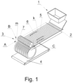
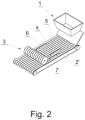
- a machine for recovering tobacco shown in Fig. 1 comprises a supply unit 1 for feeding defective or substandard cigarettes to the feeder 2 at the end of which a cutting apparatus 3 for opening the cigarettes 6 is located. Below the cutting apparatus 3 the feeder is arranged, e.g. a drum feeder, below which there is a receiving device 4 for receiving the cut cigarettes 6, whereas the receiving device 4 is shaped in the form of a vibrating conveyor for example, which transports the cigarettes to an apparatus (not shown) for taking tobacco out of the cigarettes or the receiving device can be an apparatus for taking the tobacco out of the cut cigarettes 6.
- the feeder 2 is provided with longitudinal grooves 5 arranged in the conveying direction, for orientating the cigarettes 6 so that the axes k of the cigarettes 6 are set in accordance with the conveying direction before feeding them to the cutting apparatus 3.
- the axes k of the cigarettes 6 moving along the grooves 5, are arranged in a plane A during orienting the cigarettes 6 along the grooves 5, before feeding the cigarettes 6 to the cutting apparatus 3.
- the opening apparatus 3 may have a set of disc knives 7 mounted on a common axis m lying on a plane B located in parallel to the plane A.
- the cutting apparatus 3 for cutting the cigarettes 6 is arranged over a linear conveyor belt 12 provided with grooves 5.
- Fig. 3 is a perspective enlarged view of the apparatus for cutting the cigarettes.
- the revolving disc knife 7 for cutting the cigarettes 6 is mounted on a shaft 8, wherein the rotation axis m of the knife 7 lies in a plane B parallel to the plane A which is a plane in which the axes k of the cigarettes 6 move along the grooves 5.
- Plane C perpendicular to the axis m, in which the disc knife 7 lies, is perpendicular to the plane A, wherein the plane C does not pass through the axis k of the cigarette 6 and is spaced from it.
- the distance e ( Fig. 5 ), over which the plane C is offset, is such that the knife 7 reaches the cigarette 6 in the vicinity of the side wall of the groove 5.
- a disc knife 7 may be formed as a multi-tooth knife or may have one cutting edge. Parallel to the plane C of the knife 7, loosely mounted rotating pressing ring 10 is located. The axis of rotation of the pressing ring 10 is movable but the axis is always parallel to the axis m of the knife 7.
- a movement limiter of the ring 10 is provided, the movement limiter is in the form of a limiting rod 18, which position might be adjustable in direction 18B ( fig. 7 ) parallel to the direction of transport of the cigarettes 6.
- the limiting rod 18 may be formed as rotating or non-rotating.
- the rolling movement 10D of the ring 10 related to the belt 12 forced by the movement of the belt 12 in the direction T can cause a rotational movement 18A of a limiting rod 18 designed as a rotating element.
- Fig. 4 is a partially sectional view of an embodiment of the apparatus, not according to the invention.
- a belt 12 used on the feeder 2 is made of elastic material and is shown in cross-section E-E indicated in fig. 7 , whereas the disc knife 7 is shown in a view in a direction parallel to the plane of the disc knife 7.
- the cigarette 6 pressed into the groove 5 is also schematically shown.
- the groove 5 of the belt 12 is provided with two walls 13 and 14 orientated at an angle ⁇ of 20° to 60°, wherein the connection of the walls 13 and 14 provided at the bottom of the groove 5 may be rounded.
- a pressing ring 10 consists of a thicker cylindrical part 10A, a truncated cone shaped part 10B and a thinner cylindrical part 10C.
- the ring 10 may consist only of a cylindrical part 10A and a cone shaped part 10B having the rounded edge at the larger base.
- the larger base of part 10B is facing the knife 7.
- the pressing ring 10 may be in contact with the knife 7 or a gap may be provided between the knife 7 and the pressing ring 10.
- Fig. 5 shows a view similar to that of Fig. 4 .
- the belt 22 is provided with many grooves 25, wherein the groove 25 has one wall 23 arranged vertically, parallel to the plane of the knife 7 and the second wall 24 arranged at an angle ⁇ to the wall 23.
- the connection between the walls 23 and 24 is formed as the bottom 26.
- the bottom 26 is perpendicular to the wall 23, that is parallel to the inner surface 27 of the belt 22.
- the wall 24 is arranged at an angle of 30° to 70° related to the surface 27.
- the pressing ring 20 is made in the form of two cylindrical parts 20A and 20B, the part 20A being a pressing portion, while the part 20B could be used for rolling the pressing ring 20 along the belt 22.
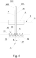
- Fig. 6 shows yet another embodiment of the apparatus, not according to the invention in a partial section view.
- the belt 32 is provided with many grooves 35, wherein the groove 35 has one wall 33 orientated vertically, parallel to the plane of the knife 7, and the second wall 34 is arc-shaped in cross-section, i.e. viewing on a straight arranged section of the belt, the wall 34 will be a sector of a shaft.
- the connection between the walls 33 and 34 may be formed as a flat or rounded bottom 36, in the embodiment shown in fig. 6 , the bottom 36 is flat and perpendicular to the wall 33 and parallel to the surface 37.
- the pressing ring 30 is provided with a conical peripheral surface 30C for pressing the cigarettes, the smaller base 30B of the cone is facing the knife disc 7.
- the walls of the groove may have any other shape ensuring the locking of the cigarette in the groove by any kind of the pressing member, which may also be made as a sliding member.
- the capsules 11 contained within the mouthpiece of the cigarette 6 were shown. As it can be seen, by offsetting the plane of the knife 7 so that the plane does not pass through the longitudinal axis k of the cigarette 6, the knife 7 does not crush or cut the capsule 11, which would result in a discharge of an aromatic substance from the capsule 11 and pollution of recovered tobacco.
- Figs. 7 and 8 are a side views of an apparatus according to the invention.
- a disc knife 7 and a pressing ring 10 are shown in a view in a direction perpendicular to the plane of the disc knife 7, wherein the disc knife 7 and the pressing ring 10 are located on a straight section of the feeder 2.
- the disc knife 7 rotates in the direction indicated 7A, and a rotational movement is forced by the rotation of the shaft 8 in the direction 8A.
- the pressing ring 10 is loosely mounted and when the ring 10 does not press the cigarette into the groove, it is supported on the edges of the walls 13 and 14 and rolls in the direction indicated 10D with the movement of the belt 12 in the direction T of the feeder 2.
- the movement is conveyed respectively by the surfaces 10A and 20B.
- the pressing ring 10 has an outer diameter greater than an outer diameter of the disc knife 7, but in each embodiment an inner diameter of the pressing ring 10 is greater than a diameter of the shaft 8.
- a rotating element 18 for determining the movement of the pressing ring 10 is located in front of the disc knife 7 (viewed in the direction T of cigarettes conveying); the rotating element 18 is used to change the position of the pressing ring 10 against the disc knife 7.
- the limiting element 18 can be driven or can receive the drive from the rolling pressing ring 10 and rotate in the direction 18A.
- the rotating limiting element 18 is provided with typical position adjustment means for adjustment in the direction 18B (not shown).
- the operation of the pressing ring 10 is also affected by the angle of inclination of the feeder 2.
- Tests revealed that the arrangement of the feeder 2 and the cutting apparatus 3 at an angle ⁇ to the horizontal direction in the range of 20° to 50° is particularly advantageous.
- the cigarette 6 is moved in the groove 5. At some point, immediately after getting in contact with the pressing ring 10, the tip of the cigarette 6 is pressed against the walls 13 and 14 of the groove 5. For example, as shown in fig. 4 , the cigarette 6 is pressed against a truncated cone shaped part of the periphery of the ring 10B and a cylindrical part 10C. This results first in locking the tip of the cigarette 6 relative to the groove 5. Then, during the further movement, the cigarette 6 is gradually locked over its entire length.
- the operation of the pressing ring 10 is such that when the conveyor 12 moves, it causes the gradual distortion of the cigarette and pressing it between the walls 13 and 14.
- the cigarette 6 is moved in the direction T and gradually approaches the disc knife 7. Since the pressing ring 10 is arranged in front of the disc knife 7, the cigarette will get in contact with the disc knife 7 ( fig. 7 ) starting from the part which has already been locked between the walls 13 and 14 of the groove 5. As the cigarette 6 is being moved in the groove 5, further pressing and locking in the groove 5 takes place and then cutting of the cigarette 6 is performed. In other words the cigarette 6 after getting in contact with the pressing ring 10 to getting in contact with the disc knife 7 travels a certain distance d, and during travelling this distance d the cigarette 6 is locked relative to the walls of the groove 5 over the increasing length. When the cigarette 6 gets in contact with the disc knife 7, the cigarette 6 is locked at a sufficiently long length to be stable hold by the walls of the groove 5 when cutting the wrapper.
- the length of the distance d, after travelling of which cutting of the cigarette 6 starts, can be changed (wherein the distance d is measured from the point at which the cigarette 6 locking starts).
- the distance d travelled by the cigarette 6 from the point of contact of the cigarette 6 with the pressing ring to the point of contact of the cigarette 6 with the disc knife should be within the range from 0.2 to 5 times of the cigarette diameter, preferably within the range from 0.25 to 1.5 times of the cigarette diameter.
Landscapes
- Manufacturing Of Cigar And Cigarette Tobacco (AREA)
Claims (12)
- Vorrichtung zum Zigarettenschneiden, wobei die Zigaretten (6) eine Achse (k) aufweisen, wobei die Vorrichtung zum Zigarettenschneiden folgendes umfassteine Zuführung (2), die zum Transportieren der Zigaretten (6) geeignet ist, wobei die Zuführung (2) Folgendes umfasst
mindestens eine Führungsrille (5, 25), die entlang der Zuführung (2) angeordnet ist, wobei die Führungsrille (5, 25) mit einer ersten Wand (23), einer zweiten Wand (24) und einem Boden (26) versehen ist, der zwischen der ersten Wand (23) und der zweiten Wand (24) der Führungsrille (5, 25) angeordnet ist,eine rotierende Welle (8), die oberhalb der Zuführung (2) angeordnet ist,mindestens ein rotierendes Scheibenmesser (7) zum Schneiden der Zigaretten (6) entlang der Achse (k) der Zigaretten (6), wobei das rotierende Scheibenmesser (7) auf der rotierenden Welle (8) angeordnet ist, wobei das rotierende Scheibenmesser (7) in einer von der Achse (k) der aufzuschneidenden Zigarette (6) beabstandeten Ebene (C) positioniert ist,einen Pressring (10, 20) zum Pressen der Zigaretten (6) gegen die erste Wand (23) und die zweite Wand (24) der Führungsrille (5, 25), wobei der Pressring (10, 20) lose um die rotierende Welle (8) herum bewegbar ist und der Pressring (10, 20) neben dem rotierenden Scheibenmesser (7) angeordnet ist,wobei die Anordnung der ersten Wand (23) und der zweiten Wand (24) der Führungsrille (5, 25) relativ zueinander es ermöglicht, vor dem Schneiden jeder Zigarette (6) die Zigarette (6) mit Hilfe des Pressrings (10, 20) zu blockieren, indem die Zigarette (6) zwischen die erste Wand (23) und die zweite Wand (24) der Führungsrille (5, 25) bei gleichzeitiger Verformung der Zigarette (6) geschoben wird,dadurch gekennzeichnet, dassdie erste Wand (23) der Führungsrille (5, 25) senkrecht zum Boden (26) der Führungsrille (5, 25) steht und die zweite Wand (24) der Führungsrille (5, 25) in einem stumpfen Winkel (β) zum Boden (26) der Führungsrille (5, 25) ausgerichtet ist, das rotierende Scheibenmesser (7) ist an der ersten Wand (23) positioniert, und der Pressring (10, 20) und das rotierende Scheibenmesser (7) befinden sich oberhalb eines geraden Abschnitts der Zuführung (2). - Eine Vorrichtung nach Anspruch 1, dadurch gekennzeichnet, dass die erste Wand (23) und die zweite Wand (24) der Führungsrille (5, 25) in einem Winkel (α) von 20° bis 60° zueinander angeordnet sind.
- Eine Vorrichtung nach Anspruch 1 oder 2, dadurch gekennzeichnet, dass die zweite Wand (24) in einem Winkel (β) von etwa 110° bis etwa 150° in Bezug auf den Boden (26) der Führungsrille (5, 25) angeordnet ist.
- Eine Vorrichtung nach Anspruch 1, dadurch gekennzeichnet, dass die Position des Pressrings (10, 20) in Bezug auf die rotierende Welle (8) des rotierenden Scheibenmessers (7) mittels eines Begrenzungselements (18) bestimmt wird, das parallel zur Achse (m) der rotierenden Welle (8) des rotierenden Scheibenmessers (7) ausgerichtet ist, wobei das Begrenzungselement (18) in Bewegungsrichtung (T) der Zuführung (2) gesehen vor der rotierenden Welle (8) des rotierenden Scheibenmessers (7) angeordnet ist.
- Eine Vorrichtung nach Anspruch 4, dadurch gekennzeichnet, dass die Position des Begrenzungselements (18) in einer Richtung parallel zur Bewegungsrichtung (T) der Zuführung (2) einstellbar ist.
- Eine Vorrichtung nach Anspruch 4 oder 5, dadurch gekennzeichnet, dass die Position des Begrenzungselements (18) so beschaffen ist, dass die von der Zigarette (6) zurückgelegte Strecke (d) ausgehend von dem Punkt, an dem die Zigarette (6) mit dem Pressring (10, 20) in Berührung kommt, bis zu dem Punkt, an dem die Zigarette mit dem rotierenden Scheibenmesser (7) in Berührung kommt, im Bereich des 0,2- bis 5-fachen des Zigarettendurchmessers liegt, vorzugsweise im Bereich des 0,25- bis 1,5-fachen des Zigarettendurchmessers.
- Eine Vorrichtung nach einem der vorhergehenden Ansprüche, dadurch gekennzeichnet, dass der Pressring (10, 20) einen Außendurchmesser hat, der größer ist als der Durchmesser des rotierenden Scheibenmessers (7).
- Eine Vorrichtung nach einem der vorhergehenden Ansprüche, dadurch gekennzeichnet, dass der Pressring (10) einen peripheren kegelstumpfförmigen Oberflächenteil aufweist, dessen größere Basis dem rotierenden Scheibenmesser (7) zugewandt ist.
- Eine Vorrichtung nach einem der Ansprüche 1 bis 7, dadurch gekennzeichnet, dass der Pressring einen peripheren kegelstumpfförmigen Oberflächenteil aufweist, dessen kleinere Basis dem rotierenden Scheibenmesser (7) zugewandt ist.
- Ein Verfahren zum Schneiden von Zigaretten, wobei die Zigaretten (6) eine Achse (k) aufweisen, wobei das Verfahren den Transport der Zigaretten (6) durch eine Zuführung (2) in mindestens eine Führungsrille (5, 25), die entlang der Zuführung (2) angeordnet ist, umfasst, wobei die Führungsrille (5, 25) mit einer ersten Wand (23), einer zweiten Wand (24) und einem Boden (26) versehen ist, der zwischen der ersten Wand (23) und der zweiten Wand (24) der Führungsrille (5, 25) angeordnet ist,Schneiden der Zigaretten (6) entlang der Achse (k) der Zigaretten (6) mittels eines rotierenden Scheibenmessers (7), das auf einer oberhalb der Führungsrille (5, 25) angeordneten rotierenden Welle (8) angebracht ist, wobei das rotierende Scheibenmesser (7) in einer von der Achse (k) der aufzuschneidenden Zigarette (6) beabstandeten Ebene (C) angeordnet ist,wobei die aufzuschneidende Zigarette (6) mittels eines Pressrings (10, 20) gegen die erste Wand (23) und die zweite Wand (24) der Führungsrille (5, 25) gepresst wird, wobei der Pressring (10, 20, 30) lose um die rotierende Welle (8) bewegbar ist, wobei der Pressring (10, 20) neben dem rotierenden Scheibenmesser (7) angeordnet ist,wobei die aufzuschneidende Zigarette (6) vor dem Schneiden mit Hilfe des Pressrings (10, 20) blockiert wird, indem die Zigarette (6) zwischen die erste Wand (23) und die zweite Wand (24) der Führungsrille (5, 25) bei gleichzeitiger Verformung der Zigarette (6) geschoben wird,wobei das Blockieren und Schneiden der Zigarette (6) über einen geraden Abschnitt der Zuführung (2) erfolgt,dadurch gekennzeichnet, dassdie erste Wand (23) der Führungsrille (5, 25) senkrecht zum Boden (26) der Führungsrille (5, 25) steht und die zweite Wand (24) der Führungsrille (5, 25) in einem stumpfen Winkel (β) zum Boden (26) der Führungsrille (5, 25) ausgerichtet ist, das rotierende Scheibenmesser (7) ist an der ersten Wand (23) positioniert, undder Pressring (10, 20) und der rotierende Scheibenmesser (7) befinden sich oberhalb eines geraden Abschnitts der Zuführung (2) .
- Ein Verfahren nach Anspruch 10, dadurch gekennzeichnet, dass eine Position des Pressrings (10, 20) in Bezug auf die rotierende Welle (8) des rotierenden Scheibenmessers (7) durch ein Begrenzungselement (18) bestimmt wird, das parallel zur Achse (m) der rotierenden Welle (8) des rotierenden Scheibenmessers (7) und in Bewegungsrichtung (T) der Zuführung (2) gesehen vor der rotierenden Welle (8) angeordnet ist.
- Ein Verfahren nach Anspruch 10, dadurch gekennzeichnet, dass eine Position des Begrenzungselements (18) in einer Richtung parallel zur Bewegungsrichtung (T) der Zuführung (2) einstellbar ist.
Applications Claiming Priority (2)
| Application Number | Priority Date | Filing Date | Title |
|---|---|---|---|
| PL412866A PL230026B1 (pl) | 2015-06-26 | 2015-06-26 | Zespół do rozcinania papierosów i sposób rozcinania papierosów |
| PCT/IB2016/053775 WO2016207847A1 (en) | 2015-06-26 | 2016-06-24 | An apparatus for cutting cigarettes and a method of cutting cigarettes |
Publications (2)
| Publication Number | Publication Date |
|---|---|
| EP3313210A1 EP3313210A1 (de) | 2018-05-02 |
| EP3313210B1 true EP3313210B1 (de) | 2024-06-19 |
Family
ID=56684128
Family Applications (1)
| Application Number | Title | Priority Date | Filing Date |
|---|---|---|---|
| EP16751004.9A Active EP3313210B1 (de) | 2015-06-26 | 2016-06-24 | Vorrichtung zum schneiden von zigaretten und verfahren zum schneiden von zigaretten |
Country Status (3)
| Country | Link |
|---|---|
| EP (1) | EP3313210B1 (de) |
| PL (1) | PL230026B1 (de) |
| WO (1) | WO2016207847A1 (de) |
Families Citing this family (2)
| Publication number | Priority date | Publication date | Assignee | Title |
|---|---|---|---|---|
| CN109303350B (zh) * | 2018-11-08 | 2021-12-28 | 郑州格兰高环境工程有限公司 | 一种烟支定位剖切装置 |
| CN115102007B (zh) * | 2022-06-30 | 2025-06-03 | 宜昌市睿程佑自动化设备有限公司 | 自动排线及裁线机 |
Family Cites Families (4)
| Publication number | Priority date | Publication date | Assignee | Title |
|---|---|---|---|---|
| US4261790A (en) * | 1979-08-22 | 1981-04-14 | Philip Morris Incorporated | Apparatus for stripping filter paper from filter rod |
| PL222076B1 (pl) * | 2010-03-11 | 2016-06-30 | Int Tobacco Machinery Poland Spółka Z Ograniczoną Odpowiedzialnością | Sposób otwierania opakowania papierosa i zespół do otwierania opakowań papierosów maszyny do odzyskiwania tytoniu z papierosów uszkodzonych lub niepełnowartościowych |
| PL221773B1 (pl) * | 2012-02-28 | 2016-05-31 | Int Tobacco Machinery Poland | Sposób i układ do porządkowania elementów prętopodobnych oraz układ do odzyskiwania tytoniu z papierosów odpadowych |
| EP2730182A3 (de) * | 2012-11-08 | 2015-04-08 | Köhl Maschinenbau AG | Vorrichtung und Verfahren zur Rückgewinnung von Rauchartikelteilen aus Rauchartikeln |
-
2015
- 2015-06-26 PL PL412866A patent/PL230026B1/pl unknown
-
2016
- 2016-06-24 EP EP16751004.9A patent/EP3313210B1/de active Active
- 2016-06-24 WO PCT/IB2016/053775 patent/WO2016207847A1/en not_active Ceased
Also Published As
| Publication number | Publication date |
|---|---|
| PL230026B1 (pl) | 2018-09-28 |
| WO2016207847A1 (en) | 2016-12-29 |
| PL412866A1 (pl) | 2017-01-02 |
| EP3313210A1 (de) | 2018-05-02 |
| WO2016207847A4 (en) | 2017-02-16 |
Similar Documents
| Publication | Publication Date | Title |
|---|---|---|
| EP2364605B1 (de) | Verfahren und Vorrichtung zur Rückgewinnung von Tabak aus fehlerhaften Zigaretten | |
| KR101398745B1 (ko) | 필터요소 절단시스템 | |
| EP2206585B1 (de) | Drehscheibenmesser, Verfahren zur Montage eines Drehscheibenmessers und Verfahren zur Demontage eines Drehscheibenmessers | |
| GB2494159A (en) | Cigarette processing assembly for reclaiming tobacco | |
| EP3206511B1 (de) | Verfahren und vorrichtung zum nachweis gedrehter segmente in einer maschine in der tabakverarbeitenden industrie und maschine zur herstellung multisegmentierter stangen mit solch einer vorrichtung | |
| US12108782B2 (en) | Apparatus and method for manufacturing tobacco industry products | |
| CN113197339B (zh) | 爆珠植入机 | |
| EP2675304B1 (de) | Verfahren und vorrichtung zur öffnung von zigarettenabfall enthaltenden zigaretten | |
| WO2016207847A1 (en) | An apparatus for cutting cigarettes and a method of cutting cigarettes | |
| EP2730182A2 (de) | Vorrichtung und Verfahren zur Rückgewinnung von Rauchartikelteilen aus Rauchartikeln | |
| JP2005524543A (ja) | 切断機械 | |
| JP2005538713A (ja) | 特にタバコ用の切断機械の切断区域内に有機植物材料を送給するための装置 | |
| PL244138B1 (pl) | Układ orientująco-podający do podawania papierosów i nadawania papierosom orientacji wzdłużnej, urządzenie do odzyskiwania tytoniu zawierające ten układ, sposób podawania papierosów i nadawania orientacji wzdłużnej papierosom oraz sposób odzyskiwania tytoniu | |
| EP2636323A2 (de) | Zigarettenfilter, Zigarette sowie Verfahren und Maschine zur Herstellung eines Zigarettenfilters oder einer Zigarette | |
| CN1985688B (zh) | 烟草加工工业的条杆切割装置 | |
| WO2004080215A1 (en) | Tobacco cutting apparatus | |
| CN101502972A (zh) | 用于对杆状元件打孔的组件 | |
| EP0137604A1 (de) | Egalisiervorrichtung für Tabak | |
| US3156246A (en) | Cigarette machine for making mouthpiece cigarettes | |
| EP4570083A1 (de) | Vorrichtung zum trennen eines stabförmigen mehrsegmentartikels der tabakindustrie | |
| EP3662766A1 (de) | Stützträgerelement für eine tabakmaschine | |
| GB2132877A (en) | Feed mechanism for tobacco cutting machines | |
| JP2008029923A (ja) | 細断処理装置 |
Legal Events
| Date | Code | Title | Description |
|---|---|---|---|
| STAA | Information on the status of an ep patent application or granted ep patent |
Free format text: STATUS: THE INTERNATIONAL PUBLICATION HAS BEEN MADE |
|
| PUAI | Public reference made under article 153(3) epc to a published international application that has entered the european phase |
Free format text: ORIGINAL CODE: 0009012 |
|
| STAA | Information on the status of an ep patent application or granted ep patent |
Free format text: STATUS: REQUEST FOR EXAMINATION WAS MADE |
|
| 17P | Request for examination filed |
Effective date: 20171201 |
|
| AK | Designated contracting states |
Kind code of ref document: A1 Designated state(s): AL AT BE BG CH CY CZ DE DK EE ES FI FR GB GR HR HU IE IS IT LI LT LU LV MC MK MT NL NO PL PT RO RS SE SI SK SM TR |
|
| AX | Request for extension of the european patent |
Extension state: BA ME |
|
| RAP1 | Party data changed (applicant data changed or rights of an application transferred) |
Owner name: INTERNATIONAL TOBACCO MACHINERY POLAND SP. Z O.O. |
|
| DAV | Request for validation of the european patent (deleted) | ||
| DAX | Request for extension of the european patent (deleted) | ||
| STAA | Information on the status of an ep patent application or granted ep patent |
Free format text: STATUS: EXAMINATION IS IN PROGRESS |
|
| 17Q | First examination report despatched |
Effective date: 20210625 |
|
| GRAP | Despatch of communication of intention to grant a patent |
Free format text: ORIGINAL CODE: EPIDOSNIGR1 |
|
| STAA | Information on the status of an ep patent application or granted ep patent |
Free format text: STATUS: GRANT OF PATENT IS INTENDED |
|
| INTG | Intention to grant announced |
Effective date: 20240117 |
|
| GRAS | Grant fee paid |
Free format text: ORIGINAL CODE: EPIDOSNIGR3 |
|
| GRAA | (expected) grant |
Free format text: ORIGINAL CODE: 0009210 |
|
| STAA | Information on the status of an ep patent application or granted ep patent |
Free format text: STATUS: THE PATENT HAS BEEN GRANTED |
|
| AK | Designated contracting states |
Kind code of ref document: B1 Designated state(s): AL AT BE BG CH CY CZ DE DK EE ES FI FR GB GR HR HU IE IS IT LI LT LU LV MC MK MT NL NO PL PT RO RS SE SI SK SM TR |
|
| REG | Reference to a national code |
Ref country code: GB Ref legal event code: FG4D |
|
| REG | Reference to a national code |
Ref country code: CH Ref legal event code: EP |
|
| REG | Reference to a national code |
Ref country code: DE Ref legal event code: R096 Ref document number: 602016088032 Country of ref document: DE |
|
| PG25 | Lapsed in a contracting state [announced via postgrant information from national office to epo] |
Ref country code: BG Free format text: LAPSE BECAUSE OF FAILURE TO SUBMIT A TRANSLATION OF THE DESCRIPTION OR TO PAY THE FEE WITHIN THE PRESCRIBED TIME-LIMIT Effective date: 20240619 |
|
| PG25 | Lapsed in a contracting state [announced via postgrant information from national office to epo] |
Ref country code: FI Free format text: LAPSE BECAUSE OF FAILURE TO SUBMIT A TRANSLATION OF THE DESCRIPTION OR TO PAY THE FEE WITHIN THE PRESCRIBED TIME-LIMIT Effective date: 20240619 Ref country code: HR Free format text: LAPSE BECAUSE OF FAILURE TO SUBMIT A TRANSLATION OF THE DESCRIPTION OR TO PAY THE FEE WITHIN THE PRESCRIBED TIME-LIMIT Effective date: 20240619 |
|
| REG | Reference to a national code |
Ref country code: LT Ref legal event code: MG9D |
|
| PG25 | Lapsed in a contracting state [announced via postgrant information from national office to epo] |
Ref country code: GR Free format text: LAPSE BECAUSE OF FAILURE TO SUBMIT A TRANSLATION OF THE DESCRIPTION OR TO PAY THE FEE WITHIN THE PRESCRIBED TIME-LIMIT Effective date: 20240920 |
|
| REG | Reference to a national code |
Ref country code: NL Ref legal event code: MP Effective date: 20240619 |
|
| PG25 | Lapsed in a contracting state [announced via postgrant information from national office to epo] |
Ref country code: LV Free format text: LAPSE BECAUSE OF FAILURE TO SUBMIT A TRANSLATION OF THE DESCRIPTION OR TO PAY THE FEE WITHIN THE PRESCRIBED TIME-LIMIT Effective date: 20240619 |
|
| PG25 | Lapsed in a contracting state [announced via postgrant information from national office to epo] |
Ref country code: NO Free format text: LAPSE BECAUSE OF FAILURE TO SUBMIT A TRANSLATION OF THE DESCRIPTION OR TO PAY THE FEE WITHIN THE PRESCRIBED TIME-LIMIT Effective date: 20240919 Ref country code: LV Free format text: LAPSE BECAUSE OF FAILURE TO SUBMIT A TRANSLATION OF THE DESCRIPTION OR TO PAY THE FEE WITHIN THE PRESCRIBED TIME-LIMIT Effective date: 20240619 Ref country code: HR Free format text: LAPSE BECAUSE OF FAILURE TO SUBMIT A TRANSLATION OF THE DESCRIPTION OR TO PAY THE FEE WITHIN THE PRESCRIBED TIME-LIMIT Effective date: 20240619 Ref country code: GR Free format text: LAPSE BECAUSE OF FAILURE TO SUBMIT A TRANSLATION OF THE DESCRIPTION OR TO PAY THE FEE WITHIN THE PRESCRIBED TIME-LIMIT Effective date: 20240920 Ref country code: FI Free format text: LAPSE BECAUSE OF FAILURE TO SUBMIT A TRANSLATION OF THE DESCRIPTION OR TO PAY THE FEE WITHIN THE PRESCRIBED TIME-LIMIT Effective date: 20240619 Ref country code: BG Free format text: LAPSE BECAUSE OF FAILURE TO SUBMIT A TRANSLATION OF THE DESCRIPTION OR TO PAY THE FEE WITHIN THE PRESCRIBED TIME-LIMIT Effective date: 20240619 Ref country code: RS Free format text: LAPSE BECAUSE OF FAILURE TO SUBMIT A TRANSLATION OF THE DESCRIPTION OR TO PAY THE FEE WITHIN THE PRESCRIBED TIME-LIMIT Effective date: 20240919 |
|
| PG25 | Lapsed in a contracting state [announced via postgrant information from national office to epo] |
Ref country code: NL Free format text: LAPSE BECAUSE OF FAILURE TO SUBMIT A TRANSLATION OF THE DESCRIPTION OR TO PAY THE FEE WITHIN THE PRESCRIBED TIME-LIMIT Effective date: 20240619 |
|
| REG | Reference to a national code |
Ref country code: AT Ref legal event code: MK05 Ref document number: 1695327 Country of ref document: AT Kind code of ref document: T Effective date: 20240619 |
|
| PG25 | Lapsed in a contracting state [announced via postgrant information from national office to epo] |
Ref country code: NL Free format text: LAPSE BECAUSE OF FAILURE TO SUBMIT A TRANSLATION OF THE DESCRIPTION OR TO PAY THE FEE WITHIN THE PRESCRIBED TIME-LIMIT Effective date: 20240619 |
|
| PG25 | Lapsed in a contracting state [announced via postgrant information from national office to epo] |
Ref country code: PT Free format text: LAPSE BECAUSE OF FAILURE TO SUBMIT A TRANSLATION OF THE DESCRIPTION OR TO PAY THE FEE WITHIN THE PRESCRIBED TIME-LIMIT Effective date: 20241021 |
|
| PG25 | Lapsed in a contracting state [announced via postgrant information from national office to epo] |
Ref country code: PT Free format text: LAPSE BECAUSE OF FAILURE TO SUBMIT A TRANSLATION OF THE DESCRIPTION OR TO PAY THE FEE WITHIN THE PRESCRIBED TIME-LIMIT Effective date: 20241021 |
|
| PG25 | Lapsed in a contracting state [announced via postgrant information from national office to epo] |
Ref country code: PL Free format text: LAPSE BECAUSE OF FAILURE TO SUBMIT A TRANSLATION OF THE DESCRIPTION OR TO PAY THE FEE WITHIN THE PRESCRIBED TIME-LIMIT Effective date: 20240619 |
|
| PG25 | Lapsed in a contracting state [announced via postgrant information from national office to epo] |
Ref country code: EE Free format text: LAPSE BECAUSE OF FAILURE TO SUBMIT A TRANSLATION OF THE DESCRIPTION OR TO PAY THE FEE WITHIN THE PRESCRIBED TIME-LIMIT Effective date: 20240619 |
|
| PG25 | Lapsed in a contracting state [announced via postgrant information from national office to epo] |
Ref country code: IS Free format text: LAPSE BECAUSE OF FAILURE TO SUBMIT A TRANSLATION OF THE DESCRIPTION OR TO PAY THE FEE WITHIN THE PRESCRIBED TIME-LIMIT Effective date: 20241019 Ref country code: AT Free format text: LAPSE BECAUSE OF FAILURE TO SUBMIT A TRANSLATION OF THE DESCRIPTION OR TO PAY THE FEE WITHIN THE PRESCRIBED TIME-LIMIT Effective date: 20240619 |
|
| PG25 | Lapsed in a contracting state [announced via postgrant information from national office to epo] |
Ref country code: CZ Free format text: LAPSE BECAUSE OF FAILURE TO SUBMIT A TRANSLATION OF THE DESCRIPTION OR TO PAY THE FEE WITHIN THE PRESCRIBED TIME-LIMIT Effective date: 20240619 |
|
| PG25 | Lapsed in a contracting state [announced via postgrant information from national office to epo] |
Ref country code: SK Free format text: LAPSE BECAUSE OF FAILURE TO SUBMIT A TRANSLATION OF THE DESCRIPTION OR TO PAY THE FEE WITHIN THE PRESCRIBED TIME-LIMIT Effective date: 20240619 Ref country code: RO Free format text: LAPSE BECAUSE OF FAILURE TO SUBMIT A TRANSLATION OF THE DESCRIPTION OR TO PAY THE FEE WITHIN THE PRESCRIBED TIME-LIMIT Effective date: 20240619 |
|
| PG25 | Lapsed in a contracting state [announced via postgrant information from national office to epo] |
Ref country code: ES Free format text: LAPSE BECAUSE OF FAILURE TO SUBMIT A TRANSLATION OF THE DESCRIPTION OR TO PAY THE FEE WITHIN THE PRESCRIBED TIME-LIMIT Effective date: 20240619 Ref country code: SM Free format text: LAPSE BECAUSE OF FAILURE TO SUBMIT A TRANSLATION OF THE DESCRIPTION OR TO PAY THE FEE WITHIN THE PRESCRIBED TIME-LIMIT Effective date: 20240619 |
|
| PG25 | Lapsed in a contracting state [announced via postgrant information from national office to epo] |
Ref country code: SM Free format text: LAPSE BECAUSE OF FAILURE TO SUBMIT A TRANSLATION OF THE DESCRIPTION OR TO PAY THE FEE WITHIN THE PRESCRIBED TIME-LIMIT Effective date: 20240619 Ref country code: SK Free format text: LAPSE BECAUSE OF FAILURE TO SUBMIT A TRANSLATION OF THE DESCRIPTION OR TO PAY THE FEE WITHIN THE PRESCRIBED TIME-LIMIT Effective date: 20240619 Ref country code: RO Free format text: LAPSE BECAUSE OF FAILURE TO SUBMIT A TRANSLATION OF THE DESCRIPTION OR TO PAY THE FEE WITHIN THE PRESCRIBED TIME-LIMIT Effective date: 20240619 Ref country code: PL Free format text: LAPSE BECAUSE OF FAILURE TO SUBMIT A TRANSLATION OF THE DESCRIPTION OR TO PAY THE FEE WITHIN THE PRESCRIBED TIME-LIMIT Effective date: 20240619 Ref country code: IS Free format text: LAPSE BECAUSE OF FAILURE TO SUBMIT A TRANSLATION OF THE DESCRIPTION OR TO PAY THE FEE WITHIN THE PRESCRIBED TIME-LIMIT Effective date: 20241019 Ref country code: ES Free format text: LAPSE BECAUSE OF FAILURE TO SUBMIT A TRANSLATION OF THE DESCRIPTION OR TO PAY THE FEE WITHIN THE PRESCRIBED TIME-LIMIT Effective date: 20240619 Ref country code: EE Free format text: LAPSE BECAUSE OF FAILURE TO SUBMIT A TRANSLATION OF THE DESCRIPTION OR TO PAY THE FEE WITHIN THE PRESCRIBED TIME-LIMIT Effective date: 20240619 Ref country code: CZ Free format text: LAPSE BECAUSE OF FAILURE TO SUBMIT A TRANSLATION OF THE DESCRIPTION OR TO PAY THE FEE WITHIN THE PRESCRIBED TIME-LIMIT Effective date: 20240619 Ref country code: AT Free format text: LAPSE BECAUSE OF FAILURE TO SUBMIT A TRANSLATION OF THE DESCRIPTION OR TO PAY THE FEE WITHIN THE PRESCRIBED TIME-LIMIT Effective date: 20240619 |
|
| REG | Reference to a national code |
Ref country code: CH Ref legal event code: PL |
|
| PG25 | Lapsed in a contracting state [announced via postgrant information from national office to epo] |
Ref country code: LU Free format text: LAPSE BECAUSE OF NON-PAYMENT OF DUE FEES Effective date: 20240624 |
|
| PG25 | Lapsed in a contracting state [announced via postgrant information from national office to epo] |
Ref country code: MC Free format text: LAPSE BECAUSE OF FAILURE TO SUBMIT A TRANSLATION OF THE DESCRIPTION OR TO PAY THE FEE WITHIN THE PRESCRIBED TIME-LIMIT Effective date: 20240619 |
|
| REG | Reference to a national code |
Ref country code: DE Ref legal event code: R097 Ref document number: 602016088032 Country of ref document: DE |
|
| PG25 | Lapsed in a contracting state [announced via postgrant information from national office to epo] |
Ref country code: MC Free format text: LAPSE BECAUSE OF FAILURE TO SUBMIT A TRANSLATION OF THE DESCRIPTION OR TO PAY THE FEE WITHIN THE PRESCRIBED TIME-LIMIT Effective date: 20240619 |
|
| PG25 | Lapsed in a contracting state [announced via postgrant information from national office to epo] |
Ref country code: DK Free format text: LAPSE BECAUSE OF FAILURE TO SUBMIT A TRANSLATION OF THE DESCRIPTION OR TO PAY THE FEE WITHIN THE PRESCRIBED TIME-LIMIT Effective date: 20240619 |
|
| PG25 | Lapsed in a contracting state [announced via postgrant information from national office to epo] |
Ref country code: IE Free format text: LAPSE BECAUSE OF NON-PAYMENT OF DUE FEES Effective date: 20240624 |
|
| PG25 | Lapsed in a contracting state [announced via postgrant information from national office to epo] |
Ref country code: CH Free format text: LAPSE BECAUSE OF NON-PAYMENT OF DUE FEES Effective date: 20240630 Ref country code: BE Free format text: LAPSE BECAUSE OF NON-PAYMENT OF DUE FEES Effective date: 20240630 |
|
| PLBE | No opposition filed within time limit |
Free format text: ORIGINAL CODE: 0009261 |
|
| STAA | Information on the status of an ep patent application or granted ep patent |
Free format text: STATUS: NO OPPOSITION FILED WITHIN TIME LIMIT |
|
| REG | Reference to a national code |
Ref country code: BE Ref legal event code: MM Effective date: 20240630 |
|
| 26N | No opposition filed |
Effective date: 20250320 |
|
| GBPC | Gb: european patent ceased through non-payment of renewal fee |
Effective date: 20240919 |
|
| PGFP | Annual fee paid to national office [announced via postgrant information from national office to epo] |
Ref country code: DE Payment date: 20250619 Year of fee payment: 10 |
|
| PG25 | Lapsed in a contracting state [announced via postgrant information from national office to epo] |
Ref country code: GB Free format text: LAPSE BECAUSE OF NON-PAYMENT OF DUE FEES Effective date: 20240919 |
|
| PG25 | Lapsed in a contracting state [announced via postgrant information from national office to epo] |
Ref country code: FR Free format text: LAPSE BECAUSE OF NON-PAYMENT OF DUE FEES Effective date: 20240819 |
|
| PG25 | Lapsed in a contracting state [announced via postgrant information from national office to epo] |
Ref country code: SE Free format text: LAPSE BECAUSE OF FAILURE TO SUBMIT A TRANSLATION OF THE DESCRIPTION OR TO PAY THE FEE WITHIN THE PRESCRIBED TIME-LIMIT Effective date: 20240619 |
|
| PGFP | Annual fee paid to national office [announced via postgrant information from national office to epo] |
Ref country code: IT Payment date: 20250620 Year of fee payment: 10 |
|
| PG25 | Lapsed in a contracting state [announced via postgrant information from national office to epo] |
Ref country code: CY Free format text: LAPSE BECAUSE OF FAILURE TO SUBMIT A TRANSLATION OF THE DESCRIPTION OR TO PAY THE FEE WITHIN THE PRESCRIBED TIME-LIMIT; INVALID AB INITIO Effective date: 20160624 |
|
| PG25 | Lapsed in a contracting state [announced via postgrant information from national office to epo] |
Ref country code: HU Free format text: LAPSE BECAUSE OF FAILURE TO SUBMIT A TRANSLATION OF THE DESCRIPTION OR TO PAY THE FEE WITHIN THE PRESCRIBED TIME-LIMIT; INVALID AB INITIO Effective date: 20160624 |