EP3314141B1 - Bremstrommel - Google Patents
Bremstrommel Download PDFInfo
- Publication number
- EP3314141B1 EP3314141B1 EP16728297.9A EP16728297A EP3314141B1 EP 3314141 B1 EP3314141 B1 EP 3314141B1 EP 16728297 A EP16728297 A EP 16728297A EP 3314141 B1 EP3314141 B1 EP 3314141B1
- Authority
- EP
- European Patent Office
- Prior art keywords
- connection
- brake drum
- region
- another
- shell portion
- Prior art date
- Legal status (The legal status is an assumption and is not a legal conclusion. Google has not performed a legal analysis and makes no representation as to the accuracy of the status listed.)
- Active
Links
Images


Classifications
-
- F—MECHANICAL ENGINEERING; LIGHTING; HEATING; WEAPONS; BLASTING
- F16—ENGINEERING ELEMENTS AND UNITS; GENERAL MEASURES FOR PRODUCING AND MAINTAINING EFFECTIVE FUNCTIONING OF MACHINES OR INSTALLATIONS; THERMAL INSULATION IN GENERAL
- F16D—COUPLINGS FOR TRANSMITTING ROTATION; CLUTCHES; BRAKES
- F16D65/00—Parts or details
- F16D65/02—Braking members; Mounting thereof
- F16D65/10—Drums for externally- or internally-engaging brakes
-
- F—MECHANICAL ENGINEERING; LIGHTING; HEATING; WEAPONS; BLASTING
- F16—ENGINEERING ELEMENTS AND UNITS; GENERAL MEASURES FOR PRODUCING AND MAINTAINING EFFECTIVE FUNCTIONING OF MACHINES OR INSTALLATIONS; THERMAL INSULATION IN GENERAL
- F16D—COUPLINGS FOR TRANSMITTING ROTATION; CLUTCHES; BRAKES
- F16D65/00—Parts or details
- F16D65/02—Braking members; Mounting thereof
- F16D2065/13—Parts or details of discs or drums
- F16D2065/1304—Structure
-
- F—MECHANICAL ENGINEERING; LIGHTING; HEATING; WEAPONS; BLASTING
- F16—ENGINEERING ELEMENTS AND UNITS; GENERAL MEASURES FOR PRODUCING AND MAINTAINING EFFECTIVE FUNCTIONING OF MACHINES OR INSTALLATIONS; THERMAL INSULATION IN GENERAL
- F16D—COUPLINGS FOR TRANSMITTING ROTATION; CLUTCHES; BRAKES
- F16D65/00—Parts or details
- F16D65/02—Braking members; Mounting thereof
- F16D2065/13—Parts or details of discs or drums
- F16D2065/134—Connection
- F16D2065/1344—Connection permanent, e.g. by casting
-
- F—MECHANICAL ENGINEERING; LIGHTING; HEATING; WEAPONS; BLASTING
- F16—ENGINEERING ELEMENTS AND UNITS; GENERAL MEASURES FOR PRODUCING AND MAINTAINING EFFECTIVE FUNCTIONING OF MACHINES OR INSTALLATIONS; THERMAL INSULATION IN GENERAL
- F16D—COUPLINGS FOR TRANSMITTING ROTATION; CLUTCHES; BRAKES
- F16D2200/00—Materials; Production methods therefor
- F16D2200/0004—Materials; Production methods therefor metallic
- F16D2200/0026—Non-ferro
- F16D2200/003—Light metals, e.g. aluminium
-
- F—MECHANICAL ENGINEERING; LIGHTING; HEATING; WEAPONS; BLASTING
- F16—ENGINEERING ELEMENTS AND UNITS; GENERAL MEASURES FOR PRODUCING AND MAINTAINING EFFECTIVE FUNCTIONING OF MACHINES OR INSTALLATIONS; THERMAL INSULATION IN GENERAL
- F16D—COUPLINGS FOR TRANSMITTING ROTATION; CLUTCHES; BRAKES
- F16D2200/00—Materials; Production methods therefor
- F16D2200/0034—Materials; Production methods therefor non-metallic
- F16D2200/0039—Ceramics
- F16D2200/0047—Ceramic composite, e.g. C/C composite infiltrated with Si or B, or ceramic matrix infiltrated with metal
Definitions
- the present invention relates to a brake drum, in particular a brake drum of a commercial vehicle, which consists of a jacket region and a connection region.
- Brake drums of the type in question are well known in the art.
- brake drums made of an aluminum composite material in which aluminum is die-cast around a porous ceramic core.
- the problem with such a system is that the production of the ceramic core and the aluminum die-casting process are very complicated and expensive.
- brake drums are known in which ceramic particles are mixed before casting with the liquid aluminum alloy.
- the problem with such systems is that the ceramic particles are not specifically arranged in the region of the later wear surface, but find themselves distributed throughout the casting. As a result, a material failure can take place on the vehicle in the highly stressed connection region of the brake drum. Incidentally, it is not possible to use a high ceramic content, so that a worse wear behavior is the result.
- US 2005/0167214 A1 relates to a brake drum having a cladding region 31 and a connection region, wherein the connection region comprises 38% of a ceramic in a metal and the cladding region of 20% ceramic in a metal.
- US 2009/0056134 A1 relates to a cast torsion damper with an annular friction surface.
- WO 99/00607 relates to a composite brake drum for an engine of a vehicle or the like.
- the brake drum comprises a metallic drum section, a steel drum back and a mounting side.
- US 2004/0000386 A1 relates to molded articles, in particular brake drums comprising a metal matrix.
- FR 2 734 195 relates to a method of manufacturing an aluminum alloy member having a friction surface.
- DE 10 2011 54484 A1 relates to a brake drum for vehicles, wherein a base body made of aluminum and a friction body made of steel are made independently of each other and then are materially interconnected by friction welding. During friction welding, both materials go into a partially molten state, so that excess aluminum flows in grooves of the friction body and there forms a Verklamm ceremoniess für through the undercuts.
- the main body is made of an aluminum casting or wrought alloy with a copper content of less than 0.05%.
- the main body has a peripheral wall and a radially extending wall. The peripheral wall is to be equated with the shell region and the radially extending wall with the connection region according to the present application.
- a brake drum in particular a commercial vehicle, comprising a jacket region which has a friction surface which is arranged rotationally symmetrical to a rotation axis, a connection region which has a mounting section, wherein the jacket region and the connection region are made of different materials and connected to one another ,
- the jacket region expediently has a friction surface which is designed to be brought into contact with a brake lining of a brake shoe.
- the jacket region and in particular its friction surface must be made of a particularly stiff and abrasion-resistant material.
- the friction surface is arranged rotationally symmetrical with respect to a rotation axis, which corresponds to the essence of the axis of rotation of the vehicle axle.
- the jacket region is essentially cylindrical, wherein one end face of the jacket region expediently has a first connection section for connection to the connection region.
- this has a connection area with a mounting portion which serves to fix the brake drum to a vehicle part.
- the mounting portion may be provided with holes or bolts in order to arrange the brake drum on a wheel hub rotating about the vehicle axis.
- the connection region expediently does not extend, or only slightly, into the cylindrical part of the jacket region, wherein "slight" is in particular less than 0.1 times the extension of the jacket region along the axis of rotation.
- the cladding region and the connection region are formed of different materials and connected to one another.
- the cladding region is a composite of aluminum and another, certain first element
- the connection region consists of an alloy of aluminum and another second element.
- the cladding region and the bonding region are made separately from each other.
- the cladding region and the connection region are made separately from each other or independently before their connection.
- the jacket region and the connection region can be produced by means of a primary molding process, for example by casting. In the case of a separate production, therefore, the jacket region and the connection region do not form a one-piece construction during the production process, but are separate from one another or separate parts, which are joined together only in a subsequent method step.
- the jacket region is at least partially, preferably completely, formed from a metal-matrix composite material, in particular aluminum-ceramic composite material.
- the part of the jacket region, which includes the friction surface may be formed of a metal-matrix composite material, the opposite, as a rule outwardly oriented part or surface of the cladding region, may be formed only of metal and does not have to include a composite material.
- the entire cladding region is formed entirely from a metal-matrix composite material, so that the cladding region is predominantly, in particular more than 90% and particularly preferably completely formed of a metal-matrix composite.
- the metal advantageously forms a coherent matrix, wherein, for example, the ceramic forms a reinforcing phase.
- ceramic particles may be, for example, silicon carbide.
- Carbon-based short or continuous fibers or foams with open porosity can likewise be used as the composite material.
- the jacket region is formed at least partially, preferably completely, from a material which is formed from a discontinuous phase, preferably from ceramic particles, and a continuous phase, preferably from aluminum.
- the discontinuous phase thus forms the reinforcing phase and is in particular formed of loose ceramic particles or carbon particles or carbon fibers. These are particularly expediently introduced into a molten metal, for example of aluminum or titanium.
- a particularly advantageous homogeneous distribution of the discontinuous phase, in particular the ceramic particles allows, which leads to particularly reliable product properties.
- the volume percent ratio of ceramic particles to aluminum is in the range of 0.4 to 4, preferably 1 to 4 and more preferably 1.5 to 4. This can improve the wear behavior and thus extend the life of the brake drum. This is especially true in comparison to known from the prior art, integrally cast brake drums with ceramic particles, in which the ceramic component is much lower due to the one-piece casting and the connection region. It is particularly expedient if the jacket area adjacent to Friction surface has a volume percentage ratio of ceramic particles to aluminum in the range of 2.8 to 4, which decreases radially (ie perpendicular to the axis of rotation) and adjacent to the friction surface opposite outside in the range of 2.8 to 4.
- connection region is at least partially, preferably completely, made of a homogeneous material, preferably aluminum, steel or an alloy.
- the connection region can thus be partially, in particular in the region of the mounting section, preferably predominantly and more preferably at least 90% and particularly preferably completely formed from a homogeneous material.
- homogeneous means that the connection region is formed from a material of the same composition.
- the connection region may be formed of a metal such as aluminum, steel or an alloy thereof.
- the connection region can also be formed from plastic or a fiber composite material.
- the cladding region has a first connection section and the connection region has a second connection region via which the cladding region and the connection region are non-positively connected to one another and / or positively and / or materially.
- the connection sections thus represent, in particular, the contact sections between the connection area and the jacket area.
- the connection of the jacket area and the connection area can be effected via adhesion and / or positive engagement and / or material connection.
- a fluid connection leads to a particularly high level of operational reliability, while a force and form-liquid connection can advantageously also be reversible, so that, for example, after wear of the jacket area, this can be replaced by a new jacket area and the connection area can be used again.
- the first and the second connecting portion are integrally connected to one another via a weld.
- the cohesive connection is produced by a friction welding process, in particular a rotary friction welding process.
- the first and the second connecting section are non-positively and positively connected, in particular via connecting means.
- the connecting means may in this case be provided as separate elements, for example screws or bolts, so that, for example, in the connection area a plurality of holes, which can be penetrated by bolts, are provided, to which threaded recesses are arranged in the jacket area, into which the Engage bolt.
- the connection sections can be thermally heated, for example, while the jacket region is cooled so that they can be guided into one another and, after temperature equalization, enter into an interference fit with one another.
- an undercut is provided at the connection region and / or jacket region in the respective connection sections, so that a non-positive and positive connection is provided.
- the first connecting portion has a first connecting surface and the second connecting portion has a second connecting surface, wherein the connecting surfaces are preferably formed substantially congruent to each other.
- the connecting surfaces thus expediently represent the contact surfaces between the jacket region and the connection region.
- the connection surfaces are essentially parallel or congruent or designed to fit one another.
- the connecting surfaces need not be congruent or aligned with each other, but may also be mutually inclined so that they have a gap, for example in Shape of a V, form each other, which can be filled by a weld metal.
- the connecting surfaces extend perpendicularly and / or parallel and / or inclined to the axis of rotation.
- the connecting surfaces are then inclined to the axis of rotation when they extend at an angle not equal to 0 ° or 90 ° to the axis of rotation.
- the inclined formation of the connecting surfaces is particularly preferred in a welded joint. The same applies to the arrangement of the connecting surfaces perpendicular to the axis of rotation, since they can be combined with each other particularly well via a friction welding process.
- a configuration of connecting surfaces has proved to be particularly advantageous, in which the connecting surfaces form the shape of a step or an undercut and thus are not only formed exclusively perpendicular or parallel or inclined to the rotation axis, but combine a combination of the above-mentioned orientations.
- the ratio of the extent of the attachment region to that of the jacket region along the axis of rotation is between 0.05 and 0.6, preferably between 0.1 and 0.5 and particularly preferably between 0.17 and 0.4.
- a ratio in the lower region of 0.05 to 0.2 has proven to be particularly advantageous.
- a ratio in the upper value range between 0.4 to 0.6 has proven to be particularly advantageous.
- connection region between the application region and the jacket region has resulted at a ratio of between 0.1 and 0.5, since this provides a good balance between bending moments and torsional moments acting on the connection point between the connection region and jacket region. without unnecessarily restricting the width of the friction surfaces (that is, the extension of the friction surface along the rotation axis).
- FIG. 1 is a cross-sectional view of a portion of a first preferred embodiment of the brake drum according to the invention shown.
- This consists of a cladding region 2 and a connection region 4.
- the cladding region 2 and the connection region 4 are formed from different materials and originally produced separately from one another.
- the jacket region 2 and the connection region 4 are connected to one another.
- the jacket region 2 has a friction surface 6, which is designed to engage with a brake lining (not shown).
- the friction surface 6 is arranged rotationally symmetrical about the axis of rotation x.
- connection region 4 has a mounting section 8 in order to fasten the brake drum to a vehicle part, in particular a wheel hub rotating about the vehicle axle.
- the mounting portion 8 may in this case have through holes for attachment of wheel bolts.
- the jacket region 2 has a first connection section 10 and the connection region 4 has a second connection section 12.
- connection surfaces which in the illustrated embodiment are inclined relative to one another and thus form a gap in the form of a V, via which a weld 14 of the jacket region 2 and the connection region 4 is provided.
- the ratio of the extent a of the connection region to the extension b of the jacket region along the rotation axis x is between 0.05 and 0.6.
- connection region 4 By making the cladding region 2 and the connection region 4 separately from each other and subsequently connected to each other, it is possible to provide a plurality of different cladding regions 2 and a plurality of different attachment regions 4 and to assemble them in the manner of a modular system, as shown in FIG. 2 is shown.
- one different connection region 4 is provided on one and the same type of jacket region.
- the upper, in FIG. 2 shown brake drum here shows a very steeply increasing connection area 4, while the middle, in FIG. 2 illustrated brake drum represents a very flat rising connection area 4.
- connection regions 4 Due to the possibility of being able to arrange different connection regions 4 on one and the same jacket region 2, it is advantageously possible to provide a brake drum system in which the brake drum can be adapted to different interfaces independently of the jacket region 2, in each case by the corresponding connection region 4 the jacket area 2 is added.
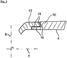
- FIG. 2 shows a sectional view of a connection region of jacket region 2 and connection region 4 of a preferred embodiment of the brake drum.
- the jacket region 2 has in its first connecting portion 10th first connection surfaces 16.
- the connection region 4 has second connection surfaces 18 in its second connection section 12.
- the connecting sections 10, 12 are in this case designed such that they form a step in that the connecting surfaces 16, 18 have a region parallel to the axis of rotation x and an axis perpendicular to the axis of rotation x.
- the first connection section 10 of the second jacket region 2 is located at least partially within the second connection section 12 of the connection region 4, since during an actuation of the brake drum the jacket region 2 is subjected to greater heating and tends to expand, thereby additionally strengthening the connection between jacket region 2 and bonding region 4.
- the connecting surfaces 16, 18 form an undercut with one another in the circumferential direction of the brake drum, so that a rotation of the second casing region 2 to the connection region 4 is prevented.
- Such an undercut is possible, for example, by forming a toothing or a wave profile on the connecting surfaces 16, 18.
Landscapes
- Engineering & Computer Science (AREA)
- General Engineering & Computer Science (AREA)
- Mechanical Engineering (AREA)
- Braking Arrangements (AREA)
Description
- Die vorliegende Erfindung betrifft eine Bremstrommel insbesondere eine Bremstrommel eines Nutzfahrzeugs, welche aus einem Mantelbereich und einem Anbindungsbereich besteht.
- Bremstrommeln der in Rede stehenden Art sind aus dem Stand der Technik hinlänglich bekannt. Beispielsweise existieren Bremstrommeln, die aus einem Aluminium-Verbund-Werkstoff hergestellt sind, bei welchen Aluminium im Druckgussverfahren um einem porösen Keramikkern gegossen wird. Problematisch bei einem derartigen System ist jedoch, dass die Herstellung des Keramikkerns sowie das Aluminiumdruckgussverfahren sehr aufwendig und teuer sind. Darüber hinaus sind Bremstrommeln bekannt, bei welchen Keramikpartikel vor dem Vergießen mit der flüssigen Aluminiumlegierung vermischt werden. Problematisch bei derartigen Systemen ist jedoch, dass die Keramikpartikel nicht gezielt im Bereich der späteren Verschleißfläche angeordnet werden, sondern sich im gesamten Gussteil verteilt wieder finden. Dies führt dazu, dass im hoch beanspruchten Anbindungsbereich der Bremstrommel am Fahrzeug ein Materialversagen stattfinden kann. Im Übrigen ist es nicht möglich, einen hohen Keramikanteil zu verwenden, sodass ein schlechteres Verschleißverhalten die Folge ist.
-
US 2005/0167214 A1 betrifft eine Bremstrommel mit einem Mantelbereich 31 und einem Anbindungsbereich, wobei der Anbindungsbereich zu 38% eine Keramik in einem Metall und der Mantelbereich zu 20% Keramik in einem Metall umfasst. -
US 2009/0056134 A1 betrifft einen gegossenen Torsionsdämpfer mit einer ringförmigen Reibfläche. -
WO 99/00607 -
US 2004/0000386 A1 betrifft gegossene Artikel, insbesondere Bremstrommeln, welche eine Metallmatrix umfassen. -
FR 2 734 195 -
DE 10 2011 54484 A1 betrifft eine Bremstrommel für Fahrzeuge, wobei ein aus Aluminium hergestellter Grundkörper und ein aus Stahl hergestellter Reibkörper unabhängig voneinander hergestellt werden und anschließend stoffschlüssig durch Reibschweißen miteinander verbunden werden. Beim Reibschweißen gehen beide Materialien in einen teilweise schmelzflüssigen Zustand über, so dass überschüssiges Aluminium in Nuten des Reibkörpers strömt und dort eine Verklammerungsstruktur durch die Hinterschneidungen bildet. Der Grundkörper wird aus einer Aluminiumguss- oder Knetlegierung mit einem Kupfergehalt von kleiner als 0,05% hergestellt. Der Grundkörper weist eine Umfangswand und eine sich radial erstreckende Wand auf. Die Umfangswand ist mit dem Mantelbereich und die sich radial erstreckende Wand mit dem Anbindungsbereich gemäß der vorliegenden Anmeldung gleichzusetzen. - Es ist daher Aufgabe der vorliegenden Erfindung, eine Bremstrommel vorzusehen, welche insbesondere im Nutzfahrzeugbereich Anwendung findet, die einen hohen Verschleißwiderstand hat, eine lange Lebensdauer gewährleistet und einfach und günstig herstellbar ist.
- Diese Aufgabe wird durch eine Bremstrommel insbesondere eines Nutzfahrzeugs, mit den Merkmalen des Anspruchs 1 gelöst. Bevorzugte Ausführungsformen ergeben sich aus den abhängigen Ansprüchen.
- Erfindungsgemäß ist eine Bremstrommel, insbesondere eines Nutzfahrzeuges, vorgesehen, umfassend einen Mantelbereich, welcher eine Reibfläche aufweist, die rotationssymmetrisch zu einer Rotationsachse angeordnet ist, einen Anbindungsbereich, welcher einen Montageabschnitt aufweist, wobei der Mantelbereich und der Anbindungsbereich aus unterschiedlichen Materialien ausgebildet und miteinander verbunden sind. Der Mantelbereich weist zweckmäßigerweise eine Reibfläche auf, welche ausgelegt ist, mit einem Bremsbelag einer Bremsbacke in Kontakt gebracht zu werden. Dementsprechend muss der Mantelbereich und insbesondere dessen Reibfläche aus besonders steifen und abriebfesten Material bestehen. Um ein optimales Bremsverhalten zu gewährleisten ist die Reibfläche rotationssymmetrisch zu einer Rotationsachse angeordnet, welche dem Wesentlichen der Rotationsachse der Fahrzeugachse entspricht. Der Mantelbereich ist im wesentlichen zylinderförmig ausgebildet, wobei eine Stirnseite des Mantelbereichs zweckmäßigerweise einen ersten Verbindungsabschnitt zur Verbindung mit dem Anbindungsbereich aufweist. Um die Bremstrommel am Fahrzeug anordnen bzw. festlegen bzw. montieren zu können, weist diese einen Anbindungsbereich mit einem Montageabschnitt auf, der zur Festlegung der Bremstrommel an einem Fahrzeugteil dient. Insbesondere kann der Montageabschnitt mit Löchern oder Bolzen versehen sein, um die Bremstrommel an einer sich um die Fahrzeugachse drehenden Radnabe anordnen zu können. Der Anbindungsbereich erstreckt sich zweckmäßigerweise nicht oder nur geringfügig in den zylindrischen Teil des Mantelbereichs hinein, wobei "geringfügig" insbesondere weniger als das 0,1-fache der Erstreckung des Mantelbereichs entlang der Rotationsachse ist. Von besonderer Bedeutung ist, dass der Mantelbereich und der Anbindungsbereich aus unterschiedlichen Materialien ausgebildet und miteinander verbunden sind. Unterschiedliche Materialien sind hierbei derart zu verstehen, dass die Gesamtzusammensetzung von Mantelbereich und Anbindungsbereich sich unterscheidet. So ist es durchaus möglich, dass der Mantelbereich ein Verbundwerkstoff aus Aluminium und einem weiteren, bestimmten ersten Element ist, wohingegen der Anbindungsbereich aus einer Legierung aus Aluminium und einem anderen zweiten Element besteht. Durch das Ausbilden von Mantelbereich und Anbindungsbereich aus unterschiedlichen Materialien kann somit gewährleistet werden, dass dem jeweiligen Bereich diejenigen Materialien zugeordnet werden, welche besonders gut die geforderten Eigenschaften erfüllen. So ist es daher möglich, im Mantelbereich ein solches Material vorzusehen, welches besonders abriebfest und hitzebeständig ist, wohingegen im Anbindungsbereich ein Material vorgesehen werden kann, welches fähig ist, besonders hohe Kräfte aufzunehmen. Um die erfindungsgemäße Bremstrommel auszubilden sind der Mantelbereich und der Anbindungsbereich miteinander verbunden. Die Verbindung kann hierbei reversibel oder irreversibel über einen Stoffschluss ausgebildet werden. Der Begriff "irreversibel" ist hierbei derart zu interpretieren, dass eine Trennung von Mantelbereich und Anbindungsbereich nur möglich ist, indem eine Zerstörung der Bremstrommel erfolgt.
- Vorzugsweise sind der Mantelbereich und der Anbindungsbereich getrennt voneinander hergestellt. In anderen Worten sind der Mantelbereich und der Anbindungsbereich vor deren Verbindung miteinander getrennt voneinander bzw. eigenständig hergestellt. So ist es besonders vorteilhafterweise möglich, eine Art Baukastensystem zu ermöglich, bei welchem eine Vielzahl von Varianten von Mantelbereichen und eine weitere Vielzahl von Varianten von Anbindungsbereichen getrennt voneinander hergestellt werden können, die dann nach Bedarf miteinander verbunden werden können. Besonders vorteilhafterweise können der Mantelbereich sowie der Anbindungsbereich mittels eines Urformverfahrens, beispielsweise durch Gießen, hergestellt sein. Bei einer voneinander getrennten Herstellung bilden daher der Mantelbereich und der Anbindungsbereich während des Herstellungsprozesses keine Einstückigkeit aus, sondern sind voneinander separate bzw. getrennte Teile, welche erst in einem anschließenden Verfahrensschritt miteinander verbunden werden.
- Vorteilhafterweise ist der Mantelbereich zumindest teilweise, vorzugsweise vollständig, aus einem Metall-Matrix-Verbundwerkstoff, insbesondere Aluminium-Keramik-Verbundwerkstoff, ausgebildet. So kann insbesondere der Teil des Mantelbereichs, welcher die Reibfläche beinhaltet, aus einem Metall-Matrix-Verbundwerkstoff ausgebildet sein, wobei der gegenüber liegende, in der Regel nach außen orientierte Teil bzw. Fläche des Mantelbereichs, lediglich aus Metall ausgebildet sein kann und keinen Verbundwerkstoff beinhalten muss. Besonders bevorzugt ist jedoch der gesamte Mantelbereich vollständig aus einem Metall-Matrix-Verbundwerkstoff gebildet, sodass der Mantelbereich überwiegend, insbesondere zu mehr als 90% und besonders vorzugsweise zu vollständig aus einem Metall-Matrix-Verbund ausgebildet ist. Hierbei bildet das Metall vorteilhafterweise eine zusammenhängende Matrix aus, wobei beispielsweise die Keramik eine Verstärkungsphase bildet. Derartige keramische Partikel können beispielsweise Siliciumcarbid sein. Als Verbundwerkstoff können gleichfalls auf Kohlenstoff basierende Kurz- oder Endlosfasern oder Schäume mit offener Porosität zum Einsatz kommen.
- In einer besonders bevorzugten Ausführungsform ist der Mantelbereich zumindest teilweise, vorzugsweise vollständig, aus einem Material ausgebildet, das aus einer diskontinuierlichen Phase, vorzugsweise aus Keramikpartikeln, und einer kontinuierlichen Phase, vorzugsweise aus Aluminium, ausgebildet. Die diskontinuierliche Phase bildet somit die Verstärkungsphase aus und ist insbesondere aus losen Keramikpartikeln oder Kohlenstoffpartikeln oder Kohlenstofffasern ausgebildet. Diese werden besonders zweckmäßigerweise in eine Metallschmelze, beispielsweise aus Aluminium oder Titan, eingebracht. Hierdurch wird eine besonders vorteilhaft homogene Verteilung der diskontinuierlichen Phase, insbesondere der Keramikpartikel, ermöglicht, was zu besonders betriebssicheren Produkteigenschaften führt.
- Zweckmäßigerweise liegt das Volumen-Prozentverhältnis von Keramikpartikeln zu Aluminium im Bereich von 0,4 bis 4, vorzugsweise 1 bis 4 und besonders vorzugsweise 1,5 bis 4. Hierdurch kann das Verschleißverhalten verbessert werden und somit die Lebensdauer der Bremstrommel verlängert werden. Dies gilt insbesondere im Vergleich zu aus dem Stand der Technik bekannten, einstückig gegossenen Bremstrommeln mit Keramikpartikeln, bei welchen der Keramikanteil aufgrund des einstückigen Gusses auch des Anbindungsbereichs sehr viel niedriger liegt. Besonders zweckmäßig ist, wenn der Mantelbereich benachbart zur Reibfläche ein Volumen-Prozentverhältnis von Keramikpartikeln zu Aluminium im Bereich von 2,8 bis 4 aufweist, welches radial (d. h. senkrecht zur Rotationsachse) abnimmt und benachbart zur der Reibfläche gegenüberliegenden Außenseite im Bereich von 2,8 bis 4 liegt.
- Vorzugsweise ist der Anbindungsbereich zumindest teilweise, vorzugsweise vollständig, aus einem homogenen Material, vorzugsweise Aluminium, Stahl oder einer Legierung, ausgebildet. Der Anbindungsbereich kann somit teilweise, insbesondere im Bereich des Montageabschnitts, vorzugsweise überwiegend und weiter vorzugsweise zu mindestens 90% und besonders vorzugsweise vollständig aus einem homogenen Material ausgebildet sein. Insbesondere bei einer vollständigen Ausbildung des Anbindungsbereichs aus homogenen Material ist dies besonders kostengünstig herstellbar und weist besonders langlebige Produkteigenschaften auf. "Homogen" bedeutet in diesem Zusammenhang, dass der Anbindungsbereich aus einem Material gleicher Zusammensetzung ausgebildet ist. So kann der Anbindungsbereich aus einem Metall, wie Aluminium, Stahl oder einer Legierung derselben ausgebildet sein. Alternativ kann der Anbindungsbereich auch aus Kunststoff oder einem Faserverbundwerkstoff ausgebildet sein.
- Vorzugsweise weist der Mantelbereich einen ersten Verbindungsabschnitt und der Anbindungsbereich einen zweiten Verbindungsbereich auf, über welche der Mantelbereich und der Anbindungsbereich kraft- und/oder form- und/oder stoffschlüssig miteinander verbunden sind. Die Verbindungsabschnitte stellen somit insbesondere die Kontaktabschnitte zwischen Anbindungsbereich und Mantelbereich dar. Die Verbindung von Mantelbereich und Anbindungsbereich kann hierbei über Kraftschluss und/oder Formschluss und/oder Stoffschluss erfolgen. Eine stoffflüssige Verbindung führt zu einer besonders hohen Betriebssicherheit, während eine kraft- und formflüssige Verbindung vorteilhafterweise auch reversibel gestaltet sein kann, sodass, beispielsweise nach Abnutzung des Mantelbereichs, dieser durch einen neuen Mantelbereich ausgetauscht werden kann und der Anbindungsbereich wieder verwendet werden kann.
- Zweckmäßigerweise sind der erste und der zweite Verbindungsabschnitt über eine Verschweißung stoffschlüssig miteinander verbunden. Besonders vorteilhaft wird die stoffschlüssige Verbindung durch ein Reibschweißverfahren, insbesondere ein Rotationsreibschweißverfahren, hergestellt. Es ist jedoch auch denkbar, andersartige Schweiß oder Lötverbindungen vorzusehen.
- Weiterhin zweckmäßigerweise sind der erste und der zweite Verbindungsabschnitt kraft- und formschlüssig, insbesondere über Verbindungsmittel, miteinander verbunden. Die Verbindungsmittel können hierbei als separate Elemente, beispielsweise Schrauben oder Bolzen, vorgesehen seien, sodass beispielsweise im Anbindungsbereich eine Vielzahl von Löchern, welche von Schraubbolzen durchgriffen werden können, vorgesehen sind, zu denen mit einem Gewinde versehende Ausnehmungen im Mantelbereich angeordnet sind, in welche die Schraubbolzen eingreifen können. Auch ist es möglich, die Verbindungsabschnitte miteinander zu verpressen. Hierbei kann der Anbindungsbereich beispielsweise thermisch erwärmt werden, während der Mantelbereich gekühlt wird, sodass diese ineinander führbar sind und nach Temperaturangleichung eine Presspassung miteinander eingehen. Auch ist möglich, dass am Anbindungsbereich und/oder Mantelbereich in den jeweiligen Verbindungsabschnitten eine Hinterschneidung vorgesehen ist, sodass eine kraft- und formschlüssige Verbindung gegeben ist.
- Vorzugsweise weisen der erste Verbindungsabschnitt eine erste Verbindungsfläche und der zweite Verbindungsabschnitt eine zweite Verbindungsfläche auf, wobei die Verbindungsflächen vorzugsweise im Wesentlichen kongruent zueinander ausgebildet sind. Die Verbindungsflächen stellen somit zweckmäßigerweise die Kontaktflächen zwischen Mantelbereich und Anbindungsbereich dar. Insbesondere bei einer formschlüssigen Verbindung sind die Verbindungsflächen im Wesentlichen parallel bzw. kongruent bzw. passend zueinander ausgebildet. Insbesondere bei einer stoffschlüssigen Verbindung müssen die Verbindungsflächen nicht kongruent bzw. fluchtend zueinander ausgebildet sein, sondern können auch zueinander derart geneigt ausgebildet sein, dass diese einen Spalt, beispielsweise in Form eines V's, zueinander ausbilden, welcher von einem Schweißgut ausgefüllt werden kann.
- In einer bevorzugten Ausführungsform erstrecken sich die Verbindungsflächen senkrecht und/oder parallel und/oder geneigt zur Rotationsachse. Die Verbindungsflächen sind dann zur Rotationsachse geneigt, wenn sich diese in einem Winkel ungleich 0° oder 90° zur Rotationsachse erstrecken. Die geneigte Ausbildung der Verbindungsflächen ist insbesondere bei einer Schweißverbindung bevorzugt. Gleiches gilt für die Anordnung der Verbindungsflächen senkrecht zur Rotationsachse, da sich diese besonders gut über ein Reibschweißverfahren miteinander verbinden lassen. Bei einer kraft- und formschlüssigen Verbindung von erstem und zweitem Verbindungsabschnitt hat sich eine Konfiguration von Verbindungsflächen als besonders vorteilhaft erwiesen, bei welcher die Verbindungsflächen die Form einer Stufe oder einer Hinterschneidung ausbilden und somit nicht nur ausschließlich senkrecht oder parallel oder geneigt zur Rotationsachse ausgebildet sind, sondern eine Kombination der vorstehend genannten Orientierungen in sich vereinen.
- Vorteilhafterweise liegt das Verhältnis der Erstreckung des Anbindungsbereichs zu der des Mantelbereichs entlang der Rotationsachse zwischen 0,05 bis 0,6, vorzugsweise zwischen 0,1 bis 0,5 und besonders vorzugsweise zwischen 0,17 bis 0,4. Bei stark ansteigenden Anbindungsbereichen, das heißt bei Anbindungsbereichen, welche eine geringe Neigung zur Senkrechten der Rotationsachse aufweisen, hat sich ein Verhältnis in unterem Bereich von 0,05 bis 0,2 als besonders vorteilhaft erwiesen. Bei sehr flach ansteigenden Anbindungsbereichen, das heißt Anbindungsbereichen deren Neigung zur Senkrechten zur Rotationsachse größer 25° ist, hat sich ein Verhältnis im oberen Wertebereich zwischen 0,4 bis 0,6 als besonders vorteilhaft erwiesen. Eine besonders vorteilhafte Positionierung des Verbindungsbereichs zwischen Anwendungsbereich und Mantelbereich hat sich bei einem Verhältnis zwischen 0,1 bis 0,5 ergeben, da hierdurch ein gutes Gleichgewicht zwischen auf die Verbindungsstelle zwischen Anbindungsbereich und Mantelbereich wirkenden Biegemomenten und Torsionsmomenten gegeben ist, ohne die Breite der Reibflächen (das heißt Erstreckung der Reibfläche entlang der Rotationsachse) unnötig einzuschränken.
- Weitere Merkmale und Eigenschaften der vorliegenden Erfindung ergeben sich aus der nachfolgenden Beschreibung von bevorzugten Ausführungsformen mit Bezug auf die beigefügten Figuren. Es zeigen:
- Figur 1
- eine Schnittansicht eines Teils einer bevorzugten Ausführungsform der erfindungsgemäßen Bremstrommel.
- Figur 2
- Schnittansichten von Teilen dreier verschiedener bevorzugter Ausführungsformen der erfindungsgemäßen Bremstrommel.
- Figur 3
- eine Schnittansicht eines Teils einer weiteren bevorzugten Ausführungsform der erfindungsgemäßen Bremstrommel.
- In
Figur 1 ist eine Querschnittsansicht eines Teils einer ersten bevorzugten Ausführungsform der erfindungsgemäßen Bremstrommel dargestellt. Diese besteht aus einem Mantelbereich 2 und einem Anbindungsbereich 4. Der Mantelbereich 2 und der Anbindungsbereich 4 sind aus unterschiedlichen Materialien ausgebildet und originär getrennt voneinander hergestellt. Um die erfindungsgemäße Bremstrommel auszubilden sind der Mantelbereich 2 und der Anbindungsbereich 4 miteinander verbunden. - Der Mantelbereich 2 weist eine Reibfläche 6 auf, die ausgelegt ist, mit einem nicht dargestellten Bremsbelag in Eingriff zu gelangen. Hierfür ist die Reibfläche 6 rotationssymmetrisch um die Rotationsachse x angeordnet.
- Der Anbindungsbereich 4 weist einen Montageabschnitt 8 auf, um die Bremstrommel an einem Fahrzeugteil, insbesondere einer sich um die Fahrzeugachse drehenden Radnabe zu befestigen. Der Montageabschnitt 8 kann hierbei Durchgangslöcher zur Befestigung von Radbolzen aufweisen.
- Um den Mantelbereich 2 und den Anbindungsbereich 4 miteinander zu verbinden, weist der Mantelbereich 2 einen ersten Verbindungsabschnitt 10 und der Anbindungsbereich 4 einen zweiten Verbindungsabschnitt 12 auf. Diese umfassen entsprechende Verbindungsflächen, welche in der dargestellten Ausführungsform zueinander geneigt sind und somit einen Spalt in Form eines V's ausbilden, über welchen eine Verschweißung 14 des Mantelbereichs 2 und des Anbindungsbereichs 4 vorgesehen ist.
- Es hat sich als zweckmäßig erwiesen, dass das Verhältnis der Erstreckung a des Anbindungsbereichs zu der Erstreckung b des Mantelbereichs entlang der Rotationsachse x zwischen 0,05 bis 0,6 liegt.
- Indem der Mantelbereich 2 und der Anbindungsbereich 4 getrennt voneinander hergestellt und daran anschließend miteinander verbunden sind, ist es möglich, eine Vielzahl von verschiedenen Mantelbereichen 2 und eine Vielzahl von unterschiedlichen Anbindungsbereichen 4 vorzusehen und diese im Sinne eines Baukastensystems zusammenzusetzen, wie dies in
Figur 2 dargestellt ist. Wie ersichtlich ist an ein und demselben Typ Mantelbereich zwei jeweils ein unterschiedlicher Anbindungsbereich 4 vorgesehen. Die obere, inFigur 2 dargestellte Bremstrommel zeigt hierbei einen sehr steil ansteigenden Anbindungsbereich 4, während der mittlere, inFigur 2 dargestellte Bremstrommel einen sehr flach ansteigenden Anbindungsbereich 4 darstellt. Durch die Möglichkeit, verschiedene Anbindungsbereiche 4 an ein und demselben Mantelbereich 2 anordnen zu können, ist es vorteilhafterweise möglich, ein Bremstrommelsystem bereit zu stellen, bei welchem unabhängig vom Mantelbereich 2 die Bremstrommel an verschiedene Schnittstellen angepasst werden kann, indem jeweils der entsprechende Anbindungsbereich 4 an den Mantelbereich 2 angefügt wird. - In
Figur 3 ist eine Schnittansicht eines Verbindungsbereichs von Mantelbereich 2 und Anbindungsbereich 4 einer bevorzugten Ausführungsform der Bremstrommel dargestellt. Der Mantelbereich 2 weist in dessen ersten Verbindungsabschnitt 10 erste Verbindungsflächen 16 auf. Entsprechend weist der Anbindungsbereich 4 in dessen zweiten Verbindungsabschnitt 12 zweite Verbindungsflächen 18 auf. Die Verbindungsabschnitte 10, 12 sind hierbei derart gestaltet, dass diese eine Stufe ausbilden, indem die Verbindungsflächen 16, 18 einen sich parallel zur Rotationsachse x und einen sich senkrecht zur Rotationsachse x erstreckenden Bereich aufweisen. Hierbei ist es besonders vorteilhaft, wenn sich - in einer Radialrichtung R gesehen - der erste Verbindungsabschnitt 10 des zweiten Mantelbereichs 2 sich zumindest teilweise innerhalb des zweiten Verbindungsabschnitts 12 des Anbindungsbereichs 4 befindet, da bei einer Betätigung der Bremstrommel der Mantelbereich 2 einer stärkeren Erwärmung ausgesetzt wird und dazu neigt, sich auszudehnen, wodurch die Verbindung zwischen Mantelbereich 2 und Anbindungsbereich 4 zusätzlich verstärkt wird. - Im Übrigen ist es besonders vorteilhaft, wenn die Verbindungsflächen 16, 18 in Umfangsrichtung der Bremstrommel miteinander eine Hinterschneidung ausbilden, sodass eine Verdrehung des zweiten Mantelbereichs 2 zum Anbindungsbereich 4 verhindert wird. Eine derartige Hinterschneidung ist beispielsweise durch Ausbilden einer Verzahnung oder eines Wellenprofils an den Verbindungsflächen 16, 18 möglich.
-
- 2
- Mantelbereich
- 4
- Anbindungsbereich
- 6
- Reibfläche
- 8
- Montageabschnitt
- 10
- erster Verbindungsabschnitt
- 12
- zweiter Verbindungsabschnitt
- 14
- Verschweißung
- 16
- erste Verbindungsfläche
- 18
- zweite Verbindungsfläche
- a, b
- Erstreckung
- R
- Radialrichtung
- x
- Rotationsachse
Claims (10)
- Bremstrommel, insbesondere eines Nutzfahrzeugs, umfassend einen Mantelbereich (2), welcher eine Reibfläche (6) aufweist, die rotationssymmetrisch zu einer Rotationsachse (x) angeordnet ist,
einen Anbindungsbereich (4), welcher einen Montageabschnitt (8) aufweist, wobei der Mantelbereich (2) und der Anbindungsbereich (4) aus unterschiedlichen Materialien ausgebildet und miteinander verbunden sind,
dadurch gekennzeichnet, dass der Mantelbereich (2) und der Anbindungsbereich (4) getrennt voneinander hergestellt sind, wobei der Mantelbereich (2) einen ersten Verbindungsabschnitt (10) und der Anbindungsbereich (4) einen zweiten Verbindungsabschnitt (12) aufweist, wobei der erste und der zweite Verbindungsabschnitt (10, 12) über eine Verschweißung (14) stoffschlüssig miteinander verbunden sind. - Bremstrommel nach Anspruch 1, wobei der Mantelbereich (2) zumindest teilweise, vorzugsweise vollständig, aus einem Metall-Matrix-Verbundwerkstoff, insbesondere Aluminium-Keramik-Verbundwerkstoff, ausgebildet ist.
- Bremstrommel nach einem der vorhergehenden Ansprüche, wobei der Mantelbereich (2) zumindest teilweise, vorzugsweise vollständig, aus einem Material ausgebildet ist, das aus einer diskontinuierlichen Phase, vorzugsweise aus Keramikpartikeln, und einer kontinuierlichen Phase, vorzugsweise aus Aluminium, ausgebildet ist.
- Bremstrommel nach einem der Ansprüche 2 oder 3, wobei das Volumen-Prozentverhältnis von Keramik-Partikeln zu Aluminium im Bereich von 0,4 bis 4, vorzugsweise 1 bis 4 und besonders vorzugsweise 1,5 bis 4liegt.
- Bremstrommel nach einem der vorhergehenden Ansprüche, wobei der Anbindungsbereich (4) zumindest teilweise, vorzugsweise vollständig, aus einem homogenen Material, vorzugsweise Aluminium, Stahl oder einer Legierung, ausgebildet ist.
- Bremstrommel nach einem der vorhergehenden Ansprüche, wobei der Mantelbereich (2) den ersten Verbindungsabschnitt (10) und der Anbindungsbereich (4) den zweiten Verbindungsabschnitt (12) aufweist, über welche der Mantelbereich (2) und der Anbindungsbereich (4) kraft- und/oder formschlüssig miteinander verbunden sind.
- Bremstrommel nach Anspruch 6, wobei der erste und der zweite Verbindungsabschnitt (10, 12) kraft-und formschlüssig, insbesondere über Verbindungsmittel, miteinander verbunden sind.
- Bremstrommel nach einem der Ansprüche 6 - 7, wobei der erste Verbindungsabschnitt (10) eine erste Verbindungsfläche (16) und der zweite Verbindungsabschnitt (12) eine zweite Verbindungsfläche (18) aufweisen, wobei die Verbindungsflächen (16, 18) vorzugsweise im Wesentlichen kongruent zueinander ausgebildet sind.
- Bremstrommel nach Anspruch 8, wobei sich die Verbindungsflächen (16, 18) senkrecht, parallel und/oder geneigt zur Rotationsachse (x) erstrecken.
- Bremstrommel nach einem der vorhergehenden Ansprüche, wobei das Verhältnis der Erstreckung (a) des Anbindungsbereichs (4) zu der Erstreckung (b) des Mantelbereichs (2) entlang der Rotationsachse (x) zwischen 0,05 bis 0,6, vorzugsweise zwischen 0,1 bis 0,5 und besonders vorzugsweise zwischen 0,17 bis 0,4 liegt.
Applications Claiming Priority (2)
| Application Number | Priority Date | Filing Date | Title |
|---|---|---|---|
| DE102015212017.1A DE102015212017B4 (de) | 2015-06-29 | 2015-06-29 | Bremstrommel |
| PCT/EP2016/063016 WO2017001157A1 (de) | 2015-06-29 | 2016-06-08 | Bremstrommel |
Publications (2)
| Publication Number | Publication Date |
|---|---|
| EP3314141A1 EP3314141A1 (de) | 2018-05-02 |
| EP3314141B1 true EP3314141B1 (de) | 2019-11-06 |
Family
ID=56117710
Family Applications (1)
| Application Number | Title | Priority Date | Filing Date |
|---|---|---|---|
| EP16728297.9A Active EP3314141B1 (de) | 2015-06-29 | 2016-06-08 | Bremstrommel |
Country Status (4)
| Country | Link |
|---|---|
| US (1) | US10663022B2 (de) |
| EP (1) | EP3314141B1 (de) |
| DE (1) | DE102015212017B4 (de) |
| WO (1) | WO2017001157A1 (de) |
Cited By (1)
| Publication number | Priority date | Publication date | Assignee | Title |
|---|---|---|---|---|
| DE102024209727A1 (de) | 2024-10-04 | 2026-04-09 | Volkswagen Aktiengesellschaft | Herstellung einer Bremstrommel |
Families Citing this family (3)
| Publication number | Priority date | Publication date | Assignee | Title |
|---|---|---|---|---|
| DE102017219924A1 (de) | 2017-11-09 | 2019-05-09 | Robert Bosch Gmbh | Bremstrommel für eine Trommelbremse eines Fahrzeugs |
| DE102018106297B4 (de) | 2018-03-19 | 2021-05-27 | Saf-Holland Gmbh | Mehrteilige Bremstrommel |
| DE102019213751A1 (de) | 2019-01-11 | 2020-07-16 | Continental Teves Ag & Co. Ohg | Gebaute Verbundbremstrommel für ein Kraftfahrzeug |
Family Cites Families (22)
| Publication number | Priority date | Publication date | Assignee | Title |
|---|---|---|---|---|
| GB502755A (de) | 1939-03-24 | |||
| US2061769A (en) * | 1935-03-19 | 1936-11-24 | Motor Wheel Corp | Method of treating brake drums |
| US2493173A (en) | 1946-05-29 | 1950-01-03 | Motor Wheel Corp | Brake drum |
| US3343927A (en) * | 1963-12-18 | 1967-09-26 | Motor Wheel Corp | Sintered metal brake drum |
| DE7121527U (de) | 1971-06-03 | 1971-11-04 | Scharf H | Zweiteilige Bremstrommel für Anhanger |
| US4067098A (en) | 1976-04-16 | 1978-01-10 | Kelsey-Hayes Company | Method of manufacturing brake drums |
| DE7913595U1 (de) | 1979-05-11 | 1979-12-20 | Aluminium Walzwerke Singen Gmbh, 7700 Singen | Bremstrommel fuer trommelbremse von fahrzeugen |
| FR2734195A1 (fr) * | 1995-05-18 | 1996-11-22 | Montupet Sa | Procede de fabrication d'une piece en alliage d'aluminium presentant une surface de frottement, et pieces realisees conformement au procede |
| US5782324A (en) | 1995-12-27 | 1998-07-21 | Dayton Walther Corporation | Composite brake drum and method for producing same |
| US6051045A (en) * | 1996-01-16 | 2000-04-18 | Ford Global Technologies, Inc. | Metal-matrix composites |
| US5927447A (en) * | 1997-06-27 | 1999-07-27 | Hayes Lemmerz International, Inc. | Composite brake drum |
| GB2351686B (en) * | 1999-05-11 | 2003-02-26 | Honda Motor Co Ltd | Molded article of metal matrix composite and method for making such an article |
| US6148498A (en) | 1999-07-30 | 2000-11-21 | Hayes Lemmerz International, Inc. | Method of making a brake drum ring |
| JP4323339B2 (ja) * | 2004-02-03 | 2009-09-02 | 日信工業株式会社 | ブレーキドラム及びその製造方法 |
| WO2007049312A1 (en) | 2005-10-28 | 2007-05-03 | Brembo Ceramic Brake Systems S.P.A. | Parking brake |
| US8020300B2 (en) * | 2007-08-31 | 2011-09-20 | GM Global Technology Operations LLC | Cast-in-place torsion joint |
| US7793703B2 (en) | 2008-06-17 | 2010-09-14 | Century Inc. | Method of manufacturing a metal matrix composite |
| DE102009032008A1 (de) * | 2009-07-06 | 2011-01-13 | Knorr-Bremse Systeme für Nutzfahrzeuge GmbH | Als Gussteil ausgebildete Bremstrommel |
| JP2011226530A (ja) | 2010-04-19 | 2011-11-10 | Toyota Motor Corp | 車両用制動装置 |
| DE102011054484A1 (de) | 2011-10-14 | 2013-04-18 | Ks Aluminium-Technologie Gmbh | Bremstrommel sowie Verfahren zur Herstellung einer derartigen Bremstrommel |
| CN103573874B (zh) * | 2012-07-31 | 2015-09-02 | 嘉兴四通车轮股份有限公司 | 一种制动鼓的制造方法以及一种制动鼓 |
| JP2016519744A (ja) | 2013-03-27 | 2016-07-07 | パフォーマンス フリクション コーポレイション | フローティング型ブレーキドラム及びハブのアセンブリ |
-
2015
- 2015-06-29 DE DE102015212017.1A patent/DE102015212017B4/de not_active Expired - Fee Related
-
2016
- 2016-06-08 EP EP16728297.9A patent/EP3314141B1/de active Active
- 2016-06-08 WO PCT/EP2016/063016 patent/WO2017001157A1/de not_active Ceased
- 2016-06-08 US US15/739,795 patent/US10663022B2/en active Active
Non-Patent Citations (1)
| Title |
|---|
| None * |
Cited By (1)
| Publication number | Priority date | Publication date | Assignee | Title |
|---|---|---|---|---|
| DE102024209727A1 (de) | 2024-10-04 | 2026-04-09 | Volkswagen Aktiengesellschaft | Herstellung einer Bremstrommel |
Also Published As
| Publication number | Publication date |
|---|---|
| DE102015212017A1 (de) | 2016-12-29 |
| WO2017001157A1 (de) | 2017-01-05 |
| US10663022B2 (en) | 2020-05-26 |
| DE102015212017B4 (de) | 2019-06-06 |
| US20180187731A1 (en) | 2018-07-05 |
| EP3314141A1 (de) | 2018-05-02 |
Similar Documents
| Publication | Publication Date | Title |
|---|---|---|
| EP2736733B1 (de) | Fahrwerksystem für nutzfahrzeuge | |
| EP0941420B1 (de) | Aus verbundgusshergestellte bremsglieder, nämlich bremstrommel, bremsscheibe oder der gleichen sowie verbundgiessverfahren zur herstellung von bremsgliedern | |
| EP2245330B1 (de) | Bremsscheibe und verfahren zu deren herstellung | |
| EP3212433B1 (de) | Fahrzeugrad mit einer verbindung zwischen einer radfelge und einer radscheibe und verfahren zu dessen herstellung | |
| EP3314141B1 (de) | Bremstrommel | |
| EP2910454B1 (de) | Fahrwerksbauteil mit Exzenterscheibenanschlag | |
| DE102005044150A1 (de) | Schwimmsattel-Scheibenbremse | |
| DE102012205410A1 (de) | Bremsscheibenanordnung für Scheibenbremsen | |
| DE102012219840B4 (de) | Bremsscheibe | |
| DE102008047190B4 (de) | Bremsscheibe | |
| DE10225035B4 (de) | Geteilter Stabilisator und Verfahren zur Herstellung einer verzahnten Anbindung des äußeren Drehteils an einen der beiden Stabilisatorteile | |
| DE102013108065A1 (de) | Elastomerlager | |
| DE102009013358A1 (de) | Bremsscheibe für ein Fahrzeug sowie Verfahren zum Herstellen einer solchen | |
| DE102016113687A1 (de) | Innenverzahntes Hohlrad für ein Spannungswellengetriebe | |
| EP3685067A1 (de) | Mehrteilige bremsscheibe | |
| EP3191326B1 (de) | Achseinheit | |
| EP1285783B1 (de) | Radnaben-Einheit und Achsschenkel für die Radaufhängung eines Kraftfahrzeuges sowie Verfahren für deren Herstellung | |
| EP3638918B1 (de) | Reibringkörper, reibringsatz zur anordnung an den radsteg eines schienenrads, sowie schienenradbremse | |
| EP3710281B1 (de) | Fahrzeugradanordnung und verfahren zur herstellung einer fahrzeugradanordnung | |
| EP2428375B1 (de) | Verfahren zur Herstellung eines Stabilisators sowie Stabilisator | |
| WO2020035618A1 (de) | Gebaute bremsscheibe und verfahren zur herstellung einer solchen bremsscheibe | |
| AT510752A1 (de) | Bremsscheibenvorrichtung | |
| DE102009021472A1 (de) | Radaufhängung für ein Kraftfahrzeug mit einer um eine Lenkachse schwenkbaren Trägereinheit für ein Kraftfahrzeugrad | |
| EP1651379A1 (de) | Fügestellenstruktur für ein reibschweissverfahren und verfahren zu deren herstellung | |
| EP0706619B1 (de) | Bremsscheibe für scheibenbremsen |
Legal Events
| Date | Code | Title | Description |
|---|---|---|---|
| STAA | Information on the status of an ep patent application or granted ep patent |
Free format text: STATUS: THE INTERNATIONAL PUBLICATION HAS BEEN MADE |
|
| PUAI | Public reference made under article 153(3) epc to a published international application that has entered the european phase |
Free format text: ORIGINAL CODE: 0009012 |
|
| STAA | Information on the status of an ep patent application or granted ep patent |
Free format text: STATUS: REQUEST FOR EXAMINATION WAS MADE |
|
| 17P | Request for examination filed |
Effective date: 20180116 |
|
| AK | Designated contracting states |
Kind code of ref document: A1 Designated state(s): AL AT BE BG CH CY CZ DE DK EE ES FI FR GB GR HR HU IE IS IT LI LT LU LV MC MK MT NL NO PL PT RO RS SE SI SK SM TR |
|
| AX | Request for extension of the european patent |
Extension state: BA ME |
|
| DAV | Request for validation of the european patent (deleted) | ||
| DAX | Request for extension of the european patent (deleted) | ||
| GRAP | Despatch of communication of intention to grant a patent |
Free format text: ORIGINAL CODE: EPIDOSNIGR1 |
|
| STAA | Information on the status of an ep patent application or granted ep patent |
Free format text: STATUS: GRANT OF PATENT IS INTENDED |
|
| INTG | Intention to grant announced |
Effective date: 20190628 |
|
| GRAS | Grant fee paid |
Free format text: ORIGINAL CODE: EPIDOSNIGR3 |
|
| GRAA | (expected) grant |
Free format text: ORIGINAL CODE: 0009210 |
|
| STAA | Information on the status of an ep patent application or granted ep patent |
Free format text: STATUS: THE PATENT HAS BEEN GRANTED |
|
| AK | Designated contracting states |
Kind code of ref document: B1 Designated state(s): AL AT BE BG CH CY CZ DE DK EE ES FI FR GB GR HR HU IE IS IT LI LT LU LV MC MK MT NL NO PL PT RO RS SE SI SK SM TR |
|
| REG | Reference to a national code |
Ref country code: GB Ref legal event code: FG4D Free format text: NOT ENGLISH |
|
| REG | Reference to a national code |
Ref country code: CH Ref legal event code: EP Ref country code: AT Ref legal event code: REF Ref document number: 1199119 Country of ref document: AT Kind code of ref document: T Effective date: 20191115 |
|
| REG | Reference to a national code |
Ref country code: IE Ref legal event code: FG4D Free format text: LANGUAGE OF EP DOCUMENT: GERMAN |
|
| REG | Reference to a national code |
Ref country code: DE Ref legal event code: R096 Ref document number: 502016007448 Country of ref document: DE |
|
| REG | Reference to a national code |
Ref country code: NL Ref legal event code: MP Effective date: 20191106 |
|
| REG | Reference to a national code |
Ref country code: LT Ref legal event code: MG4D |
|
| PG25 | Lapsed in a contracting state [announced via postgrant information from national office to epo] |
Ref country code: PT Free format text: LAPSE BECAUSE OF FAILURE TO SUBMIT A TRANSLATION OF THE DESCRIPTION OR TO PAY THE FEE WITHIN THE PRESCRIBED TIME-LIMIT Effective date: 20200306 Ref country code: SE Free format text: LAPSE BECAUSE OF FAILURE TO SUBMIT A TRANSLATION OF THE DESCRIPTION OR TO PAY THE FEE WITHIN THE PRESCRIBED TIME-LIMIT Effective date: 20191106 Ref country code: LV Free format text: LAPSE BECAUSE OF FAILURE TO SUBMIT A TRANSLATION OF THE DESCRIPTION OR TO PAY THE FEE WITHIN THE PRESCRIBED TIME-LIMIT Effective date: 20191106 Ref country code: FI Free format text: LAPSE BECAUSE OF FAILURE TO SUBMIT A TRANSLATION OF THE DESCRIPTION OR TO PAY THE FEE WITHIN THE PRESCRIBED TIME-LIMIT Effective date: 20191106 Ref country code: BG Free format text: LAPSE BECAUSE OF FAILURE TO SUBMIT A TRANSLATION OF THE DESCRIPTION OR TO PAY THE FEE WITHIN THE PRESCRIBED TIME-LIMIT Effective date: 20200206 Ref country code: GR Free format text: LAPSE BECAUSE OF FAILURE TO SUBMIT A TRANSLATION OF THE DESCRIPTION OR TO PAY THE FEE WITHIN THE PRESCRIBED TIME-LIMIT Effective date: 20200207 Ref country code: NO Free format text: LAPSE BECAUSE OF FAILURE TO SUBMIT A TRANSLATION OF THE DESCRIPTION OR TO PAY THE FEE WITHIN THE PRESCRIBED TIME-LIMIT Effective date: 20200206 Ref country code: PL Free format text: LAPSE BECAUSE OF FAILURE TO SUBMIT A TRANSLATION OF THE DESCRIPTION OR TO PAY THE FEE WITHIN THE PRESCRIBED TIME-LIMIT Effective date: 20191106 Ref country code: LT Free format text: LAPSE BECAUSE OF FAILURE TO SUBMIT A TRANSLATION OF THE DESCRIPTION OR TO PAY THE FEE WITHIN THE PRESCRIBED TIME-LIMIT Effective date: 20191106 Ref country code: NL Free format text: LAPSE BECAUSE OF FAILURE TO SUBMIT A TRANSLATION OF THE DESCRIPTION OR TO PAY THE FEE WITHIN THE PRESCRIBED TIME-LIMIT Effective date: 20191106 |
|
| PG25 | Lapsed in a contracting state [announced via postgrant information from national office to epo] |
Ref country code: HR Free format text: LAPSE BECAUSE OF FAILURE TO SUBMIT A TRANSLATION OF THE DESCRIPTION OR TO PAY THE FEE WITHIN THE PRESCRIBED TIME-LIMIT Effective date: 20191106 Ref country code: IS Free format text: LAPSE BECAUSE OF FAILURE TO SUBMIT A TRANSLATION OF THE DESCRIPTION OR TO PAY THE FEE WITHIN THE PRESCRIBED TIME-LIMIT Effective date: 20200306 Ref country code: RS Free format text: LAPSE BECAUSE OF FAILURE TO SUBMIT A TRANSLATION OF THE DESCRIPTION OR TO PAY THE FEE WITHIN THE PRESCRIBED TIME-LIMIT Effective date: 20191106 |
|
| PG25 | Lapsed in a contracting state [announced via postgrant information from national office to epo] |
Ref country code: AL Free format text: LAPSE BECAUSE OF FAILURE TO SUBMIT A TRANSLATION OF THE DESCRIPTION OR TO PAY THE FEE WITHIN THE PRESCRIBED TIME-LIMIT Effective date: 20191106 |
|
| PG25 | Lapsed in a contracting state [announced via postgrant information from national office to epo] |
Ref country code: RO Free format text: LAPSE BECAUSE OF FAILURE TO SUBMIT A TRANSLATION OF THE DESCRIPTION OR TO PAY THE FEE WITHIN THE PRESCRIBED TIME-LIMIT Effective date: 20191106 Ref country code: CZ Free format text: LAPSE BECAUSE OF FAILURE TO SUBMIT A TRANSLATION OF THE DESCRIPTION OR TO PAY THE FEE WITHIN THE PRESCRIBED TIME-LIMIT Effective date: 20191106 Ref country code: EE Free format text: LAPSE BECAUSE OF FAILURE TO SUBMIT A TRANSLATION OF THE DESCRIPTION OR TO PAY THE FEE WITHIN THE PRESCRIBED TIME-LIMIT Effective date: 20191106 Ref country code: DK Free format text: LAPSE BECAUSE OF FAILURE TO SUBMIT A TRANSLATION OF THE DESCRIPTION OR TO PAY THE FEE WITHIN THE PRESCRIBED TIME-LIMIT Effective date: 20191106 Ref country code: ES Free format text: LAPSE BECAUSE OF FAILURE TO SUBMIT A TRANSLATION OF THE DESCRIPTION OR TO PAY THE FEE WITHIN THE PRESCRIBED TIME-LIMIT Effective date: 20191106 |
|
| PGFP | Annual fee paid to national office [announced via postgrant information from national office to epo] |
Ref country code: FR Payment date: 20200623 Year of fee payment: 5 |
|
| REG | Reference to a national code |
Ref country code: DE Ref legal event code: R097 Ref document number: 502016007448 Country of ref document: DE |
|
| PG25 | Lapsed in a contracting state [announced via postgrant information from national office to epo] |
Ref country code: SM Free format text: LAPSE BECAUSE OF FAILURE TO SUBMIT A TRANSLATION OF THE DESCRIPTION OR TO PAY THE FEE WITHIN THE PRESCRIBED TIME-LIMIT Effective date: 20191106 Ref country code: SK Free format text: LAPSE BECAUSE OF FAILURE TO SUBMIT A TRANSLATION OF THE DESCRIPTION OR TO PAY THE FEE WITHIN THE PRESCRIBED TIME-LIMIT Effective date: 20191106 |
|
| PGFP | Annual fee paid to national office [announced via postgrant information from national office to epo] |
Ref country code: GB Payment date: 20200625 Year of fee payment: 5 |
|
| PLBE | No opposition filed within time limit |
Free format text: ORIGINAL CODE: 0009261 |
|
| STAA | Information on the status of an ep patent application or granted ep patent |
Free format text: STATUS: NO OPPOSITION FILED WITHIN TIME LIMIT |
|
| 26N | No opposition filed |
Effective date: 20200807 |
|
| PG25 | Lapsed in a contracting state [announced via postgrant information from national office to epo] |
Ref country code: SI Free format text: LAPSE BECAUSE OF FAILURE TO SUBMIT A TRANSLATION OF THE DESCRIPTION OR TO PAY THE FEE WITHIN THE PRESCRIBED TIME-LIMIT Effective date: 20191106 |
|
| PG25 | Lapsed in a contracting state [announced via postgrant information from national office to epo] |
Ref country code: IT Free format text: LAPSE BECAUSE OF FAILURE TO SUBMIT A TRANSLATION OF THE DESCRIPTION OR TO PAY THE FEE WITHIN THE PRESCRIBED TIME-LIMIT Effective date: 20191106 Ref country code: MC Free format text: LAPSE BECAUSE OF FAILURE TO SUBMIT A TRANSLATION OF THE DESCRIPTION OR TO PAY THE FEE WITHIN THE PRESCRIBED TIME-LIMIT Effective date: 20191106 |
|
| REG | Reference to a national code |
Ref country code: CH Ref legal event code: PL |
|
| PG25 | Lapsed in a contracting state [announced via postgrant information from national office to epo] |
Ref country code: LU Free format text: LAPSE BECAUSE OF NON-PAYMENT OF DUE FEES Effective date: 20200608 |
|
| REG | Reference to a national code |
Ref country code: BE Ref legal event code: MM Effective date: 20200630 |
|
| PG25 | Lapsed in a contracting state [announced via postgrant information from national office to epo] |
Ref country code: IE Free format text: LAPSE BECAUSE OF NON-PAYMENT OF DUE FEES Effective date: 20200608 Ref country code: CH Free format text: LAPSE BECAUSE OF NON-PAYMENT OF DUE FEES Effective date: 20200630 Ref country code: LI Free format text: LAPSE BECAUSE OF NON-PAYMENT OF DUE FEES Effective date: 20200630 |
|
| PG25 | Lapsed in a contracting state [announced via postgrant information from national office to epo] |
Ref country code: BE Free format text: LAPSE BECAUSE OF NON-PAYMENT OF DUE FEES Effective date: 20200630 |
|
| GBPC | Gb: european patent ceased through non-payment of renewal fee |
Effective date: 20210608 |
|
| PG25 | Lapsed in a contracting state [announced via postgrant information from national office to epo] |
Ref country code: GB Free format text: LAPSE BECAUSE OF NON-PAYMENT OF DUE FEES Effective date: 20210608 |
|
| PG25 | Lapsed in a contracting state [announced via postgrant information from national office to epo] |
Ref country code: TR Free format text: LAPSE BECAUSE OF FAILURE TO SUBMIT A TRANSLATION OF THE DESCRIPTION OR TO PAY THE FEE WITHIN THE PRESCRIBED TIME-LIMIT Effective date: 20191106 Ref country code: MT Free format text: LAPSE BECAUSE OF FAILURE TO SUBMIT A TRANSLATION OF THE DESCRIPTION OR TO PAY THE FEE WITHIN THE PRESCRIBED TIME-LIMIT Effective date: 20191106 Ref country code: FR Free format text: LAPSE BECAUSE OF NON-PAYMENT OF DUE FEES Effective date: 20210630 Ref country code: CY Free format text: LAPSE BECAUSE OF FAILURE TO SUBMIT A TRANSLATION OF THE DESCRIPTION OR TO PAY THE FEE WITHIN THE PRESCRIBED TIME-LIMIT Effective date: 20191106 |
|
| PG25 | Lapsed in a contracting state [announced via postgrant information from national office to epo] |
Ref country code: MK Free format text: LAPSE BECAUSE OF FAILURE TO SUBMIT A TRANSLATION OF THE DESCRIPTION OR TO PAY THE FEE WITHIN THE PRESCRIBED TIME-LIMIT Effective date: 20191106 |
|
| REG | Reference to a national code |
Ref country code: AT Ref legal event code: MM01 Ref document number: 1199119 Country of ref document: AT Kind code of ref document: T Effective date: 20210608 |
|
| PG25 | Lapsed in a contracting state [announced via postgrant information from national office to epo] |
Ref country code: AT Free format text: LAPSE BECAUSE OF NON-PAYMENT OF DUE FEES Effective date: 20210608 |
|
| P01 | Opt-out of the competence of the unified patent court (upc) registered |
Effective date: 20230505 |
|
| PGFP | Annual fee paid to national office [announced via postgrant information from national office to epo] |
Ref country code: DE Payment date: 20250318 Year of fee payment: 10 |