EP3314236B1 - System und verfahren zur messung der reflektierten verzerrung in konturierten glasscheiben - Google Patents
System und verfahren zur messung der reflektierten verzerrung in konturierten glasscheiben Download PDFInfo
- Publication number
- EP3314236B1 EP3314236B1 EP16814889.8A EP16814889A EP3314236B1 EP 3314236 B1 EP3314236 B1 EP 3314236B1 EP 16814889 A EP16814889 A EP 16814889A EP 3314236 B1 EP3314236 B1 EP 3314236B1
- Authority
- EP
- European Patent Office
- Prior art keywords
- glass sheet
- camera
- pattern
- dimension
- cameras
- Prior art date
- Legal status (The legal status is an assumption and is not a legal conclusion. Google has not performed a legal analysis and makes no representation as to the accuracy of the status listed.)
- Active
Links
Images


Classifications
-
- G—PHYSICS
- G01—MEASURING; TESTING
- G01N—INVESTIGATING OR ANALYSING MATERIALS BY DETERMINING THEIR CHEMICAL OR PHYSICAL PROPERTIES
- G01N21/00—Investigating or analysing materials by the use of optical means, i.e. using sub-millimetre waves, infrared, visible or ultraviolet light
- G01N21/84—Systems specially adapted for particular applications
- G01N21/88—Investigating the presence of flaws or contamination
- G01N21/95—Investigating the presence of flaws or contamination characterised by the material or shape of the object to be examined
- G01N21/958—Inspecting transparent materials or objects, e.g. windscreens
-
- C—CHEMISTRY; METALLURGY
- C03—GLASS; MINERAL OR SLAG WOOL
- C03B—MANUFACTURE, SHAPING, OR SUPPLEMENTARY PROCESSES
- C03B23/00—Re-forming shaped glass
- C03B23/02—Re-forming glass sheets
- C03B23/023—Re-forming glass sheets by bending
-
- C—CHEMISTRY; METALLURGY
- C03—GLASS; MINERAL OR SLAG WOOL
- C03B—MANUFACTURE, SHAPING, OR SUPPLEMENTARY PROCESSES
- C03B27/00—Tempering or quenching glass products
- C03B27/04—Tempering or quenching glass products using gas
- C03B27/0417—Controlling or regulating for flat or bent glass sheets
-
- G—PHYSICS
- G01—MEASURING; TESTING
- G01B—MEASURING LENGTH, THICKNESS OR SIMILAR LINEAR DIMENSIONS; MEASURING ANGLES; MEASURING AREAS; MEASURING IRREGULARITIES OF SURFACES OR CONTOURS
- G01B11/00—Measuring arrangements characterised by the use of optical techniques
- G01B11/24—Measuring arrangements characterised by the use of optical techniques for measuring contours or curvatures
- G01B11/25—Measuring arrangements characterised by the use of optical techniques for measuring contours or curvatures by projecting a pattern, e.g. one or more lines, moiré fringes on the object
-
- G—PHYSICS
- G01—MEASURING; TESTING
- G01N—INVESTIGATING OR ANALYSING MATERIALS BY DETERMINING THEIR CHEMICAL OR PHYSICAL PROPERTIES
- G01N21/00—Investigating or analysing materials by the use of optical means, i.e. using sub-millimetre waves, infrared, visible or ultraviolet light
- G01N21/84—Systems specially adapted for particular applications
- G01N21/88—Investigating the presence of flaws or contamination
- G01N21/89—Investigating the presence of flaws or contamination in moving material, e.g. running paper or textiles
- G01N21/8901—Optical details; Scanning details
- G01N21/8903—Optical details; Scanning details using a multiple detector array
-
- G—PHYSICS
- G05—CONTROLLING; REGULATING
- G05B—CONTROL OR REGULATING SYSTEMS IN GENERAL; FUNCTIONAL ELEMENTS OF SUCH SYSTEMS; MONITORING OR TESTING ARRANGEMENTS FOR SUCH SYSTEMS OR ELEMENTS
- G05B1/00—Comparing elements, i.e. elements for effecting comparison directly or indirectly between a desired value and existing or anticipated values
-
- G—PHYSICS
- G01—MEASURING; TESTING
- G01N—INVESTIGATING OR ANALYSING MATERIALS BY DETERMINING THEIR CHEMICAL OR PHYSICAL PROPERTIES
- G01N21/00—Investigating or analysing materials by the use of optical means, i.e. using sub-millimetre waves, infrared, visible or ultraviolet light
- G01N21/84—Systems specially adapted for particular applications
- G01N2021/845—Objects on a conveyor
-
- G—PHYSICS
- G01—MEASURING; TESTING
- G01N—INVESTIGATING OR ANALYSING MATERIALS BY DETERMINING THEIR CHEMICAL OR PHYSICAL PROPERTIES
- G01N21/00—Investigating or analysing materials by the use of optical means, i.e. using sub-millimetre waves, infrared, visible or ultraviolet light
- G01N21/84—Systems specially adapted for particular applications
- G01N21/88—Investigating the presence of flaws or contamination
- G01N21/8806—Specially adapted optical and illumination features
- G01N2021/8829—Shadow projection or structured background, e.g. for deflectometry
-
- G—PHYSICS
- G01—MEASURING; TESTING
- G01N—INVESTIGATING OR ANALYSING MATERIALS BY DETERMINING THEIR CHEMICAL OR PHYSICAL PROPERTIES
- G01N21/00—Investigating or analysing materials by the use of optical means, i.e. using sub-millimetre waves, infrared, visible or ultraviolet light
- G01N21/84—Systems specially adapted for particular applications
- G01N21/88—Investigating the presence of flaws or contamination
- G01N21/95—Investigating the presence of flaws or contamination characterised by the material or shape of the object to be examined
- G01N21/958—Inspecting transparent materials or objects, e.g. windscreens
- G01N2021/9586—Windscreens
-
- G—PHYSICS
- G01—MEASURING; TESTING
- G01N—INVESTIGATING OR ANALYSING MATERIALS BY DETERMINING THEIR CHEMICAL OR PHYSICAL PROPERTIES
- G01N2201/00—Features of devices classified in G01N21/00
- G01N2201/06—Illumination; Optics
- G01N2201/063—Illuminating optical parts
- G01N2201/0635—Structured illumination, e.g. with grating
-
- G—PHYSICS
- G06—COMPUTING OR CALCULATING; COUNTING
- G06T—IMAGE DATA PROCESSING OR GENERATION, IN GENERAL
- G06T2207/00—Indexing scheme for image analysis or image enhancement
- G06T2207/30—Subject of image; Context of image processing
- G06T2207/30108—Industrial image inspection
Definitions
- This invention relates to a system for measuring reflected optical distortion in glass sheets as per claims 1-12 and a method as per claims 13-14.
- Manufacturers of glass sheets, particularly glass sheets formed into various curved shapes for use as automotive windshields, backlites, and sidelites, are interested in measuring and evaluating the amount of optical distortion in the formed sheets that might be perceived by a human observer, such as the operator or passenger in a vehicle in which the glass may be mounted as the windshield, backlite, or sidelite.
- optical inspection system acquires images of a pre-defined, contrasting pattern transmitted through the glass sheet, and may be implemented in either a laboratory (i.e., off-line) or an in-line configuration in which the inspection system is mounted to inspect glass sheets as they are being conveyed in a processing system, such as, for example, a glass sheet heating, bending and cooling system.
- a processing system such as, for example, a glass sheet heating, bending and cooling system.
- the optical characteristics of a glass sheet may also be measured by acquiring and analyzing image data corresponding to the image of a pre-defined, contrasting pattern that is reflected from one of the surfaces of the glass sheet.
- image data corresponding to the image of a pre-defined, contrasting pattern that is reflected from one of the surfaces of the glass sheet.
- the document US5363188 provides for monitoring the transparency of laminated windshields.
- a conveyor belt that brings preassembled panes to a device for monitoring the transparency of these preassembled panes.
- This device is composed of a test pattern below the preassembled pane, illuminated by a light source below the preassembly pane and the test pattern.
- the luminous intensity of the image of the test pattern, viewed through a preassembled pane is detected by a single scanning detector e.g. a camera, situated above the pane.
- the dimensions of the scanned pattern correspond to the field of the camera disposed above the preassembled pane.
- the document US2011187855 describes a device that permits analyzing, in transmission and in reflection respectively, the defects of a transparent substrate such as a glazing panel.
- the device comprises a reference pattern, image capture means, e.g. a single matrix camera, a reference pattern illumination system and suitable processing/computation means.
- the reference pattern is formed on one face of a support panel facing the transparent substrate.
- the document US5726749 describes an inspection apparatus for inspection of a transparent sheet, e.g. an automotive windshield.
- the transparent sheet is positioned on an inspection conveyor.
- the inspection apparatus transmits beams of light through the transparent sheet as it passes through the apparatus to provide for the measurement of angular deviation caused by wedge variations and/or curvature variations in the transparent sheet.
- the rate of change of the angular deviation is then used to calculate the magnitude of the distortion in the transparent sheet.
- the document US6392754 describes an arrangement for measuring the profile of a reflective surface of a sheet. Light is projected onto the reflective surface by a single light source through a light grid. For measuring the profile, one or two cameras detect the reflected image of a contrasting pattern projected on the surface of the sheet. Preferably, two cameras are positioned at different heights to obtain a reflected image from one same area of the sheet to observe a number of light/dark sequences changes in an image section, possibly caused by a curvature or change in height of the surface.
- the document US 2010/0309328 A1 discloses non-contact, opto-electronic method to determine glass surface shape which involves pattern projection in reflection from a screen. The pattern is formed of black and white or coloured squares with a central reference pattern taken as origin of the x-y axes in the subsequent quantitative analysis of the optical distortion in formed glass sheets or panels. Use of multiple image capture devices and multiple patterns is also mentioned.
- the disclosed system, as defined in claim 1, and method, as defined in claim 13, for measuring optical distortion in a contoured glass sheet includes, as components, (1) a system and method for acquiring three-dimensional surface data corresponding to the glass sheet, and (2) a system and method for receiving the acquired surface data and performing one or more optical processing operations to analyze the optical characteristics of the glass sheet.
- the surface data acquisition system includes a conveyor for conveying the glass sheet in a first direction generally parallel to the first dimension of the glass sheet, at least two displays projecting each a preselected contrasting pattern, and at least two camera, each one of the cameras uniquely paired with one of the displays, wherein each display and camera pair are mounted in a spaced-apart relationship a known distance and angle from the surface of the glass sheet such that the camera detects the reflected image of the pattern projected on the surface of the glass sheet from its associated display.
- the surface data acquisition system includes two or more cameras, each one of the cameras being uniquely paired with one of the displays as described above, wherein each of the display and camera pairs are spaced apart from each other at least in a second direction across the second dimension of the glass sheet such that each camera detects the reflected image of the pattern projected on the surface of the glass sheet from only its associated display, and wherein the patterns detected by the two or more cameras together cover the entire surface in the direction of the second dimension of the glass sheet.
- the surface data acquisition system also includes a programmable control including at least one processor programmed to execute logic for controlling each of the cameras to acquire at least one image of the reflected pattern of the associated display on the glass sheet as the glass sheet is conveyed across the path of the projected pattern in the first direction, and logic for analyzing and combining the data acquired by the two or more cameras to construct surface data representative of the surface of the glass sheet.
- a programmable control including at least one processor programmed to execute logic for controlling each of the cameras to acquire at least one image of the reflected pattern of the associated display on the glass sheet as the glass sheet is conveyed across the path of the projected pattern in the first direction, and logic for analyzing and combining the data acquired by the two or more cameras to construct surface data representative of the surface of the glass sheet.
- the disclosed optical processing system includes, according to the claimed invention, at least one processor including logic for receiving the captured image data and performing one or more optical processing operations to analyze the optical characteristics of the glass sheet and display or otherwise report selected information associated with the analysis.
- the system for measuring optical distortion may utilize a single computer which controls the conveyor and the operation of the cameras, and includes the previously described surface data acquisition logic, as well as the optical distortion processing logic.
- the conveyor control, camera controls, surface data acquisition and optical processing may be integrated but implemented on separate or multiple processors, in one or more programmable logic controllers and/or computers.
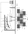
- a glass sheet optical inspection system generally indicated as 10, is disclosed and includes a conveyor 12 which conveys the glass sheet G in a first direction generally parallel to a first dimension of the glass sheet.
- the contoured glass sheet G is a generally rectangular vehicle windshield or backlight, having a first dimension which is the relatively smaller dimension (and which may alternatively be referred to as the height) and a second, relatively larger dimension (which may alternatively be referred to as the width).
- the glass sheet G is curved about one or more axes of curvature that are generally parallel to the first direction.
- the conveyor 12 may be a single conveyor dedicated solely to transporting the glass sheet G through the optical inspection system 10 which may be configured and/or operated as a stand-alone optical inspection system.
- the conveyor 12 may be one of a series of conveyors which convey the glass sheet through a variety of process stations, such as, for example, heating, forming, and annealing or tempering stations found in a typical automotive, architectural and/or solar glass sheet fabrication systems.
- the optical inspection system 10 depicted in Figures 1 and 2 also includes two or more displays 14 - 24. Each display projects a contrasting pattern, such as, for example, those patterns shown in Figures 4 and 5 , which pattern is projected onto the surface of the glass sheet as it is conveyed beneath the screens.
- the depicted system 10 also includes two or more cameras 28 - 40. Each one of the cameras 28 - 40 is uniquely paired with one of each of the corresponding number of displays 14 - 26.
- an aperture is formed in the center of each of the displays 14 - 26.
- the camera associated with a particular display is mounted such that the viewing aperture of the camera extends through the aperture in its associated display such that the principal viewing access of the camera is perpendicular to the surface the screen.
- each camera may be alternatively arranged at other locations with respect to its associated display, so long as the camera is positioned to detect the reflected image of the pattern projected on the surface of the glass sheet from that display, and not detect reflected images of patterns projected from other displays in its field of view.
- the number and placement of the displays is dependent upon the size of the displays, as well as the width and the curvature of the glass sheet.
- the camera/display pairs are positioned such that the principal viewing axis of each camera is generally perpendicular to the surface of the glass sheet.
- the total number of camera/display pairs must be sufficient such that the total number of projected patterns span the entire width of the surface of the glass sheet part to be analyzed.
- the optical inspection system 10 also includes a programmable control, depicted in this embodiment as a computer 42, which includes at least one processor programmed to detect the glass sheet as it advances on the conveyor, control each of the cameras 28 - 40 to acquire one or more images of the pattern reflected off the surface of the glass sheet as it is conveyed below the cameras/displays, construct the definition of the glass sheet surface, and perform the desired optical distortion analysis (using, for example, the technique depicted and described in Figures 7-9 , and as further described hereinafter).
- a programmable control depicted in this embodiment as a computer 42, which includes at least one processor programmed to detect the glass sheet as it advances on the conveyor, control each of the cameras 28 - 40 to acquire one or more images of the pattern reflected off the surface of the glass sheet as it is conveyed below the cameras/displays, construct the definition of the glass sheet surface, and perform the desired optical distortion analysis (using, for example, the technique depicted and described in Figures 7-9 , and as further described hereinafter).
- the system control may be programmed to acquire multiple images as the glass is conveyed in the first direction. It will be appreciated that the number of images acquire by each camera should be sufficient that the surface information developed from each image (as hereinafter described) can be combined to form a description of the entire surface across the height (i.e., in the direction of conveyance) of the glass sheet.
- the system control 42 may be programmed to acquire multiple images as the glass is conveyed in the first direction to insure that an image of the reflected pattern is obtained in a previous or subsequent image of the moving sheet for that portion of the surface of the glass sheet that, in any one of the captured images, is in the area of reflection of the display aperture.
- the number of images acquire by each camera should also be sufficient that the surface information developed from each image (as hereinafter described) can be combined to form a description of the entire surface across the height in the area in which a single image might include an image of the display aperture rather than the reflected pattern.
- the surface descriptions for each of the cameras are similarly combined to form a description of the entire surface across the width (or across the area of interest in the direction of the width) of the glass sheet.
- the screen pattern is a three-frequency pattern constructed by superimposition of three different frequency sinusoidal patterns in each of the x and y directions of the coordinate system employed by the system logic.
- the x-y coordinate system axes are chosen to be oriented such that they are coincident with the x and y axes of the display (and, as well, the y axis is parallel to the direction of travel of the conveyor and the x axis is orthogonal to the direction of travel of the conveyor).
- the sinusoidal patterns are chosen and combined to insure that the portion of the resultant pattern appearing on the display is non-repetitive, thereby ensuring that, for the image data collected, each pixel in the camera's field of view will correspond uniquely to a single point on the display.
- Each of the three frequencies may be relatively prime values, and are selected such that they are spaced apart within the envelope of frequencies bound by the minimum and maximum frequency limits of the camera's optics.
- the image of this three-frequency pattern reflected from the surface of the glass sheet may then be mathematically deconstructed into three single frequency images in each of the x and y direction. Phase information corresponding to each of the three frequencies can then be isolated and utilized as hereinafter described to develop an accurate description of the glass sheet surface.
- a two-frequency pattern may be utilized.
- This two-frequency pattern may be constructed by superimposition of two different frequency sinusoidal patterns in each of two orthogonal directions which are rotated (or skewed) about the axes that are used to separate the analysis into orthogonal components, such that each of the sinusoidal components of the pattern yields phase information in both the x and y directions.
- the x, y coordinate system axes that are used by the system logic to separate the analysis into orthogonal components are coincident with the x and y axes of the display (and the y axis is as well, coincident with the direction of conveyance).
- the orthogonal directions of the sinusoidal patterns are skewed from the x and y axes of the display. It will be appreciated, however, that any other convenient orientation may be chosen for the axes that are used by the system to separate the analysis into orthogonal components, so long as the sinusoidal patterns are rotated about the axes that are used to separate the analysis into orthogonal components to yield phase information in both the x and y directions.
- the sinusoidal patterns are chosen (relatively prime frequencies and spaced apart as described above) and combined to insure that the portion of the resultant pattern appearing on the display is non-repetitive, thereby ensuring that the image data collected that each pixel in the camera's field of view will correspond uniquely to a single point on the display.
- phase information corresponding to each of the two frequencies can be isolated and utilized as hereinafter described to develop an accurate description of the glass sheet surface.
- an accurate mathematical description of the glass sheet surface may be obtained from a single image for each point on the surface of the glass sheet from which the camera detects the reflected pattern. It is thus unnecessary to capture utilize multiple patterns, and/or multiple images, except as described herein where multiple images are acquired as the glass sheet is moved on the conveyor to construct a surface for that portion of the glass sheet that does not reflect the projected pattern in any single acquired image (e.g. , (1) that portion of the glass sheet directly below the aperture in the screen, or (2) for that portion of the glass sheet that is not in the viewing area of the camera due to the fact that the height of the glass sheet is greater that the projected pattern from the screen in the direction of conveyance).
- first zone display 20 is oriented at an angle of about 25° counterclockwise from horizontal (when viewed as in Figure 1 ), display 18 is angled at about 15° counterclockwise, display 16 is angled at about 7.5° counterclockwise, display 14 is approximately horizontal, display 22 is angled at approximately 7.5° clockwise from horizontal, display 24 is angled at about 15° clockwise, and display 26 is angled at about 25° clockwise.
- the seven displays 14 - 26 are arranged in the direction of conveyance of the glass sheet G.
- the screens are arranged such that each associated camera detects only the reflected pattern from its associated display in its field of view, and the surface areas detected by all cameras together comprise the surface across the entire width of the glass sheet part.
- the glass sheet optical inspection system 10 includes a surface data acquisition system which employs the above-described camera and display pairs and acquired images, as well as logic for developing an accurate three-dimensional description of the surface from the reflected patterns from each image, and logic for combining the surface descriptions developed from the images as hereinafter described to obtain an accurate mathematical description of the entire surface of the glass sheet.
- the glass sheet optical inspection system 10 may also, in addition to the surface data acquisition system, include one or more computers and/or programmable controls including logic for processing the acquired surface data to analyze the optical characteristics of the glass sheet.
- the optical inspection system 10 may, in turn, be incorporated into a system for fabricating glass sheets including one or more processing stations and one or more conveyors for conveying the glass sheets from station to station during processing, such as fabrication systems 200 and 300 schematically shown in Figures 10 and 11 .
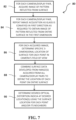
- Figure 7 describes the method 80 performed by the control logic of the disclosed optical inspection system 10.
- the system 10 determines that a glass sheet is in the appropriate position on the conveyor, the system activates the appropriate camera(s), at 82, to acquire an image of the pattern reflected from the surface of the glass sheet.
- the position of the glass sheets can be determined using conventional sensors.
- one or more additional images may be obtained from each camera, as required, as the glass sheet moves on the conveyor.
- the number of images acquired by each camera is determined by at least two considerations. First, in embodiments of the system wherein the cameras are mounted within an aperture of their associated displays, a sufficient number of images must be acquired to ensure that the system acquires a reflected image of the pattern for all of the points in the viewing area, including those points from which the display pattern is not reflected in a particular image due to the fact that it is located within the area that includes a reflection of the aperture.
- multiple images may be required as the glass is conveyed across the viewing area of the camera in embodiments of the system where the field of view of the camera is not large enough to acquire a reflection of the display pattern from the surface of the glass sheet across its entire first dimension (i.e. , the entire height) in one image.
- the system For each of the acquired images, the system, at 86, must determine the precise location in three-space of each point on the surface of the glass sheet based upon the reflected pattern in the image. As previously described, the use of a pattern which is non-repeating in the camera's viewing area ensures that each point on the display screen that is reflected within the viewing area of the camera will be uniquely associated with a pixel that detects the reflected pattern.
- Conventional image processing techniques may be employed to determine the x and y locations (i.e., in the focal plane of the camera) for each point on the surface of the glass sheet that is in the viewing area of the camera for that image. Other known processing techniques may be employed to determine the z location (a.k.a. the elevation) of each point.
- a mapping vector technique is employed (as depicted in figures 8 and 9 , and as more fully described hereinafter) to determine the elevation of each single point on the surface of the glass from the image of the reflected projected pattern.
- the x, y, and z values developed for each point in the viewing area of a particular camera are typically developed in a coordinate system associated with that camera.
- the origin of the coordinate system for each camera is set at that camera's origin 98 (as shown in Figure 8 ).
- the resulting collection of points associated with the surface in the viewing area of each camera (“the point cloud”) may then be combined for each image collected by that camera.
- the system then combines the developed surface data for each of the images acquired from all of the cameras to obtain the surface definition which identifies the location of each point in three-space for the entire surface of the glass sheet.
- the point clouds for each camera are converted to a common ("global") coordinate system, and the point clouds are then combined to form the entire surface.
- one or more other coordinate systems/origins may be selected and employed based upon a particular system's camera/display architecture and/or for computational convenience.
- the combination of the surface developed from the individual acquired images may be performed using other conventional image data processing techniques.
- the system then, at 90, performs one or more known optical processing techniques to determine any desired indicia of the reflective optics of the surface.
- the system 10 may be suitably programmed to analyze the developed surface to determine (1) various desired indicia of optical distortion, including the magnification and lens power, for selected portions, or for the entirety, of the surface of each glass sheet as it is transported through the system.
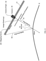
- Figures 8 and 9 illustrate, respectively, the theoretical basis and the method performed by the control logic for determining the elevation (z value) of each point on the surface of the glass from the image of the reflected projected pattern for each acquired image.
- Figure 8 illustrates the pertinent geometrical relationships between the camera 28, the display screen 14, and the surface of the glass sheet G.
- the three principles used to determine the elevation of a single point on the surface of the glass sheet from a reflected projected image are (1) the surface of any object can be defined by the normal vector 92 for each discrete point of the surface; (2) the law of reflection defines the normal vector 92 at each point by bisecting the angle between the incident ray 94 and the reflected ray 96 of light (also referred to herein as the "geometric optical” or “reflection angle” equation); and (3) the normal vector can also be defined by the differential geometry which describes each point on the surface of the glass sheet (also referred to herein as the "differential geometry” equation).
- the incident ray is defined entirely by the camera intrinsics.
- each pixel in the cameras receptor cell at the cameras origin 98 sees a point in space at varying distances through the lens.
- the reflected ray 96 is defined by a screen position and a surface point on the glass. The distance is constrained only where it intersects the incident ray 94.
- mapping vector 100 To solve the corresponding differential equations, a mapping vector 100 needs to be established, which defines, for each pixel, where the reflected ray will hit the projected pattern on the display (viewed from the camera origin). Once the mapping field (i.e. , the set of mapping vectors for each pixel in the camera's field of view) is established, the distances from the camera's origin and each discrete point on the surface can be calculated.
- n ⁇ v ⁇ m ⁇ ⁇ s v ⁇ v ⁇ ⁇ m ⁇ ⁇ s v ⁇ v ⁇ v ⁇
- n is the surface normal
- v is the camera pixel vector
- m is the mapping vector
- n ⁇ ⁇ p ⁇ ⁇ x ⁇ ⁇ p ⁇ ⁇ y
- Figure 9 illustrates how a suitably programmed computer could implement this mapping vector technique 102.
- the system develops a mapping vector that defines where the reflected ray projects to the display (again, viewed mathematically from the camera origin).
- a first expression, the geometric optical equation, at 106 defines the surface normal vector for each point on the glass sheet surface within the camera's viewing area based upon the law of reflection.
- a second equation, the differential geometry equation, at 108 defines the surface normal vector-based on the multiplication of the partial differentials which describe the point on the surface in the x, y directions.
- mapping vector to obtain the elevation, s (that is, the z distance - the distance between the glass surface and the camera origin) for each point on the glass sheet surface that is within the viewing area of the camera.
- This information coupled with the previously developed x and y locations of each surface point, yields a specific description, in x, y, and z, for each point on the surface.
- the disclosed glass sheet optical inspection system 10 may be mounted in-line to inspect glass sheets as they are transported on a conveyor associated with a glass sheet processing system which performs multiple fabricating operations on the glass sheets.
- the disclosed system 10 includes a surface data acquisition system and a computer including logic for receiving the captured image data, developing a three-dimension description of the glass sheet surface from the image data, performing one or more optical processing operations to analyze the optical characteristics of the glass sheet and displaying or otherwise reporting selected information associated with the optical analysis.
- computer 42 may be operably connected to the conveyor and cameras to perform the image acquisition, the surface development, and the optical processing described herein. Alternatively, computer 42 may be combined with one or more other computers and/or programmable controls to perform these functions.
- the system 10 may also be programmed by the user to graphically and numerically display various indicia of optical distortion, including those indicia most relevant to industry standards, or other indicia considered relevant in the industry to the analysis of the optical reflection quality of formed and fabricated glass sheets.
- the optical inspection system 10 may additionally or alternatively employ other known image processing techniques to collect and analyze the acquired image data, develop a definition of the surface, and provide various indicia of the reflected optical characteristics for each glass sheet.
- the displays 14 - 26 are light boxes that utilize conventional lighting (such as fluorescent lights) behind a translucent panel upon which the contrasting pattern is printed, painted, or otherwise applied using conventional methods.
- the digital cameras 28 - 40 are connected to the computer 60 using known methods, preferably so that the acquisition of the image by the camera may be controlled by the computer 42.
- FIG 11 illustrates a typical glass sheet heating, bending, and tempering system 200 which includes the in-line optical inspection system 10, as well as the surface data acquisition system, of the present invention.
- the glass sheets enter a heating zone 202 where the glass is softened to a temperature suitable for forming the glass into the desired shape.
- the heated glass sheet is then conveyed to a bending station 204 where the softened sheet is formed to the desired shape, and thereafter further conveyed to a cooling station 206 where the glass sheet is cooled in a controlled manner to achieve the appropriate physical characteristics.
- the glass sheet would then be conveyed out of the cooling station onto a conveyor from which the sheet is conveyed for image acquisition and analysis by the disclosed optical inspection system 10.
- the glass sheet would be moved on the conveyor 12 for further processing.
- transport and conveyance of the glass can be achieved by using known techniques such as by roller, air-float, or belt conveyors, positioners, and robotic arms, in order to handle the glass in the manner described.
- a plurality of conveyors each of which may be independently controlled to move the glass sheets through the different processing stations at speeds to efficiently govern the flow and processing of the glass sheets throughout the system 200.
- Figure 12 similarly schematically illustrates an in-line optical inspection system 10 and the associated surface data acquisition system of the present invention in a typical automotive windshield fabrication system 300, which may include a heating station 302, a bending station 304, a cooling station 306, and a lamination station 308, upstream of the optical inspection system 10.
- Selected data output by the disclosed in-line optical inspection system 10 may also be provided as input to the control logic for the associated glass sheet heating, bending, and tempering system 200 (or automotive windshield fabrication system 300) to allow the control(s) associated with one or more of the stations the glass sheet system to modify its (their) operating parameters as a function of the optical data developed from previously processed glass sheets.
- optical inspection system 10 of the present invention could alternatively be mounted in-line at various other points in the above-described and other glass sheet fabrication systems as desired to maximize the production rate of the system, so long as the optical distortion measurements are taken after the glass sheet has been formed to its final shape.
Landscapes
- Physics & Mathematics (AREA)
- Chemical & Material Sciences (AREA)
- General Physics & Mathematics (AREA)
- Engineering & Computer Science (AREA)
- Life Sciences & Earth Sciences (AREA)
- Pathology (AREA)
- Immunology (AREA)
- General Health & Medical Sciences (AREA)
- Biochemistry (AREA)
- Analytical Chemistry (AREA)
- Health & Medical Sciences (AREA)
- Materials Engineering (AREA)
- Organic Chemistry (AREA)
- Automation & Control Theory (AREA)
- Computer Vision & Pattern Recognition (AREA)
- Thermal Sciences (AREA)
- Textile Engineering (AREA)
- Length Measuring Devices By Optical Means (AREA)
- Investigating Materials By The Use Of Optical Means Adapted For Particular Applications (AREA)
Claims (14)
- System (10) zum Messen der optischen Eigenschaften einer gekrümmten Glasscheibe (G), wobei die Glasscheibe (G) eine erste Abmessung und eine zweite Abmessung aufweist, wobei die Glasscheibe (G) zumindest um eine oder mehrere Krümmungsachsen gekrümmt ist, die im Allgemeinen parallel zu der ersten Abmessung sind, wobei die Vorrichtung umfasst:eine Fördereinrichtung (12) zum Fördern der Glasscheibe (G) in einer zur ersten Abmessung der Glasscheibe (G) im Wesentlichen parallelen ersten Richtung;mindestens zwei Anzeigevorrichtungen (14-26), wobei jede Anzeigevorrichtung ein vorgewähltes Kontrastmuster projiziert;mindestens zwei Kameras (28-40; 82); undeine programmierbare Steuerung mit mindestens einem Computer (42), der mindestens einen Prozessor enthält, der programmiert ist zum Ausführen einer Logik zum Steuern jeder der Kameras (28-40; 82), um mindestens ein Bild des reflektierten Musters der zugeordneten Anzeigevorrichtung auf der Glasscheibe (G) zu erfassen, während die Glasscheibe (G) in der ersten Richtung durch den Weg des projizierten Musters gefördert wird, einer Logik zum Analysieren und Kombinieren der von den Kameras (28-40; 82) erfassten Daten, um dreidimensionale Oberflächendaten zu konstruieren, die die Form der Oberfläche der Glasscheibe (G) darstellen, und Logik zum Analysieren der die Oberfläche der Glasscheibe (G) darstellenden Daten, um optische Eigenschaften der Glasscheibe (G) zu bestimmen;dadurch gekennzeichnet, dass jede der mindestens zwei Kameras (28-40; 82) eindeutig mit einer der Anzeigevorrichtungen (14-26) verpaart ist, wobei jedes Paar von Anzeigevorrichtung und Kamera voneinander beabstandet in einem bekannten Abstand und Winkel von der Oberfläche der Glasscheibe (G) so angebracht ist, dass die Kamera das reflektierte Bild des von der ihr zugeordneten Anzeigevorrichtung auf die Oberfläche der Glasscheibe (G) projizierten Musters erfasst, und wobei jedes der Paare von Anzeigevorrichtung und Kamera zumindest in einer zweiten Richtung über die zweite Abmessung der Glasscheibe (G) voneinander beabstandet sind, so dass jede Kamera nur das reflektierte Bild des von der ihr zugeordneten Anzeigevorrichtung auf die Oberfläche der Glasscheibe (G) projizierten Musters erfasst, und wobei die von den Kameras (28-40; 82) erfassten Muster zusammen die gesamte Oberfläche in der Richtung der zweiten Abmessung der Glasscheibe (G) abdecken.
- System (10) nach Anspruch 1, dadurch gekennzeichnet, dass die erste Abmessung die kleinere Abmessung der Glasscheibe (G) ist und die zweite Abmessung die größere Abmessung der Glasscheibe (G) ist.
- System (10) nach Anspruch 1, dadurch gekennzeichnet, dass die Logik zum Analysieren und Kombinieren der von den Kameras (28-40; 82) aufgenommenen Daten, um dreidimensionale Oberflächendaten zu erstellen, die die Oberfläche der Glasscheibe (G) darstellen, eine Logik zum Erstellen von dreidimensionalen Oberflächendaten umfasst, die die gesamte Oberfläche über die zweite Abmessung der Glasscheibe (G) hinweg darstellen.
- System (10) nach Anspruch 1, dadurch gekennzeichnet, dass ein einzelnes Bild der von den Anzeigevorrichtungen (14-26) projizierten reflektierten Muster von jeder der zugeordneten Kameras (28-40; 82) nicht kombiniert werden kann, um Daten zu definieren, die für die Oberfläche der Glasscheibe (G) über die gesamte zweite Abmessung der Glasscheibe (G) hinweg repräsentativ sind, und bei dem die programmierbare Steuerung mindestens einen Prozessor, der programmiert ist, um eine Logik zum Steuern jeder der Kameras (28-40; 82) auszuführen, um mehrere Bilder des reflektierten Musters der zugeordneten Anzeigevorrichtung auf der Glasscheibe (G) zu erfassen, während die Glasscheibe (G) durch den Weg des projizierten Musters in der ersten Richtung gefördert wird, und eine Logik zum Analysieren und Kombinieren der durch die von jeder Kamera erfassten mehreren Bilder erfassten Daten umfasst, um dreidimensionale Oberflächendaten zu erstellen, die die Oberfläche der Glasscheibe (G) über die gesamte erste Abmessung der Glasscheibe (G) hinweg darstellen.
- System (10) nach Anspruch 1, dadurch gekennzeichnet, dass jede Anzeigevorrichtung eine Blende umfasst, und bei dem die zugeordnete Kamera hinter der ihr zugeordneten Anzeigevorrichtung so angebracht ist, dass die Hauptachse der Kamera im Allgemeinen senkrecht zur Oberfläche der Anzeigevorrichtung steht und das Bild von der Kamera durch die Blende empfangen wird, und bei dem die programmierbare Steuerung eine Logik zum Steuern jeder der Kameras (28-40; 82), um mehrere Bilder des reflektierten Musters der zugeordneten Anzeigevorrichtung auf der Glasscheibe (G) zu erfassen, während die Glasscheibe (G) in der ersten Richtung über mindestens eine Strecke gefördert wird, die größer ist als die Größe der Blende, und eine Logik zum Analysieren und Kombinieren der Daten aus den mehreren Bildern, um Daten zu definieren, die die Oberfläche der Glasscheibe (G) in dem Bereich darstellen, für den eines der aufgenommenen Bilder ein reflektiertes Bild der Blende enthält, umfasst.
- System (10) nach Anspruch 1, dadurch gekennzeichnet, dass die Logik zum Analysieren und Kombinieren der von den Kameras (28-40; 82) erfassten Daten zum Erstellen von dreidimensionalen Oberflächendaten, die die Oberfläche der Glasscheibe (G) darstellen, mindestens umfasst:eine Logik zum Ermitteln eines Abbildungsvektors für jedes Pixel im Blickbereich der Kamera für jedes erfasste Bild, der definiert, wo der reflektierte Strahl vom Kameraursprung zur zugeordneten Anzeigevorrichtung verläuft; undeine Logik zum Ermitteln des Höhenwertes s des Punkts für jedes Pixel im Blickbereich der Kamera für jedes erfasste Bild durch gleichzeitiges Lösen (1) der geometrisch-optischen Gleichung und (2) der geometrischen Differentialgleichung unter Verwendung des Abbildungsvektors.
- System (10) nach Anspruch 1, dadurch gekennzeichnet, dass das vorgewählte Kontrastmuster sich über den gesamten Blickbereich der Kamera nicht wiederholt.
- System (10) nach Anspruch 7, dadurch gekennzeichnet, dass das vorgewählte Kontrastmuster ein Dreifrequenzmuster ist, das durch Überlagerung von drei sinusförmigen Mustern mit unterschiedlichen Frequenzen in x- und in y-Richtung des von der Logik des Systems (10) verwendeten Koordinatensystems konstruiert ist.
- System (10) nach Anspruch 7, dadurch gekennzeichnet, dass das vorgewählte Kontrastmuster ein Zweifrequenzmuster ist, das durch Überlagerung von zwei sinusförmigen Mustern mit unterschiedlichen Frequenzen in x- und in y-Richtung des Musters gebildet wird, wobei die beiden sinusförmigen Muster mit unterschiedlichen Frequenzen in Bezug auf die Achsen des von der Logik des Systems (10) verwendeten Koordinatensystems gedreht sind.
- System (10) nach Anspruch 1, dadurch gekennzeichnet, dass die Logik zum Analysieren der die Oberfläche der Glasscheibe (G) darstellenden Daten, um optische Eigenschaften der Glasscheibe (G) zu bestimmen, eine Logik zum Bestimmen von jedem Punkt von Interesse auf der Oberfläche der Glasscheibe (G) zugeordneten ausgewählten Indizien für eine optische Verzerrung umfasst.
- System (10) nach Anspruch 10, dadurch gekennzeichnet, dass die ausgewählten Indizien für Verzerrung die Linsenstärke umfassen.
- System (10) nach Anspruch 1, dadurch gekennzeichnet, dass das System (10) in ein Fertigungssystem (200; 300) zur Herstellung von gekrümmten Glasscheiben (G) eingebaut ist, das mehrere Bearbeitungsstationen und ein oder mehrere Fördereinrichtungen zum Fördern der Glasscheibe (G) von Station zu Station während der Bearbeitung umfasst.
- Verfahren zum Messen der optischen Eigenschaften einer gekrümmten Glasscheibe (G), wobei die Glasscheibe (G) eine erste Abmessung und eine zweite Abmessung aufweist, wobei die Glasscheibe (G) zumindest um eine oder mehrere Krümmungsachsen gekrümmt ist, die im Wesentlichen parallel zu der ersten Abmessung verlaufen, wobei das Verfahren zumindest die folgenden Schritte umfasst:Fördern der Glasscheibe (G) in einer zu der ersten Abmessung der Glasscheibe (G) im Wesentlichen parallelen ersten Richtung;Projizieren eines vorgewählten Kontrastmusters von jeder der mindestens zwei Anzeigevorrichtungen (14-26) auf die Oberfläche der Glasscheibe (G);Bereitstellen von mindestens zwei Kameras (28-40; 82); undSteuern jeder der Kameras (28-40; 82), um mindestens ein Bild des reflektierten Musters der zugeordneten Anzeigevorrichtung auf der Glasscheibe (G) zu erfassen, während die Glasscheibe (G) in der ersten Richtung durch den Weg des projizierten Musters gefördert wird;Analysieren und Kombinieren der von den Kameras (28-40; 82) erfassten Daten, um dreidimensionale Oberflächendaten zu erstellen, die die Form der Oberfläche der Glasscheibe (G) darstellen; undAnalysieren der die Oberfläche der Glasscheibe (G) darstellenden Daten, um optische Eigenschaften der Glasscheibe (G) zu bestimmen;dadurch gekennzeichnet, dass der Schritt des Bereitstellens der Kameras (28-40; 82) das eindeutige Verpaaren jeder der Kameras (28-40; 82) mit einer der Anzeigevorrichtungen (14-26) und das Anbringen jedes Paars von Anzeigevorrichtung und Kamera voneinander beabstandet in einem bekannten Abstand und Winkel von der Oberfläche der Glasscheibe (G) zum Erfassen des reflektierten Bildes des von seiner zugeordneten Anzeigevorrichtung auf die Oberfläche der Glasscheibe (G) projizierten Musters umfasst, und jedes der Paare von Anzeigevorrichtung und Kamera zumindest in einer zweiten Richtung über die zweite Dimension der Glasscheibe (G) so voneinander beabstandet ist, dass jede Kamera nur das reflektierte Bild des von der ihr zugeordneten Anzeigevorrichtung auf die Oberfläche der Glasscheibe (G) projizierten Musters erfasst, wobei die von den Kameras erfassten Muster (28-40; 82) zusammen die gesamte Oberfläche in Richtung der zweiten Abmessung der Glasscheibe (G) abdecken.
- Verfahren nach Anspruch 13, dadurch gekennzeichnet, dass der Schritt des Analysierens und Kombinierens der von den Kameras (28-40; 82) erfassten Daten, um dreidimensionale Oberflächendaten zu erstellen, die die Form der Oberfläche der Glasscheibe (G) darstellen, ferner mindestens die folgenden Schritte umfasst:Ermitteln eines Abbildungsvektors für jedes Pixel im Blickbereich der Kamera und für jedes erfasste Bild, der definiert, wo der reflektierte Strahl vom Kameraursprung zur zugeordneten Anzeige verläuft, undErmitteln des Höhenwertes s des Punktes für jedes Pixel im Blickbereich der Kamera für jedes erfasste Bild durch gleichzeitiges Lösen (1) einer geometrisch-optischen Gleichung und (2) einer geometrischen Differentialgleichung unter Verwendung des Abbildungsvektors; undAnalysieren der die Oberfläche der Glasscheibe (G) darstellenden Daten, um optische Eigenschaften der Glasscheibe (G) zu bestimmen.
Applications Claiming Priority (2)
| Application Number | Priority Date | Filing Date | Title |
|---|---|---|---|
| US14/752,033 US9470641B1 (en) | 2015-06-26 | 2015-06-26 | System and method for measuring reflected optical distortion in contoured glass sheets |
| PCT/US2016/032837 WO2016209409A1 (en) | 2015-06-26 | 2016-05-17 | System and method for measuring reflected optical distortion in contoured glass sheets |
Publications (4)
| Publication Number | Publication Date |
|---|---|
| EP3314236A1 EP3314236A1 (de) | 2018-05-02 |
| EP3314236A4 EP3314236A4 (de) | 2018-12-05 |
| EP3314236B1 true EP3314236B1 (de) | 2025-07-02 |
| EP3314236C0 EP3314236C0 (de) | 2025-07-02 |
Family
ID=57120842
Family Applications (1)
| Application Number | Title | Priority Date | Filing Date |
|---|---|---|---|
| EP16814889.8A Active EP3314236B1 (de) | 2015-06-26 | 2016-05-17 | System und verfahren zur messung der reflektierten verzerrung in konturierten glasscheiben |
Country Status (7)
| Country | Link |
|---|---|
| US (2) | US9470641B1 (de) |
| EP (1) | EP3314236B1 (de) |
| CN (1) | CN107735671A (de) |
| BR (1) | BR112017028018B1 (de) |
| CA (1) | CA2990844A1 (de) |
| MX (1) | MX2018000277A (de) |
| WO (1) | WO2016209409A1 (de) |
Families Citing this family (17)
| Publication number | Priority date | Publication date | Assignee | Title |
|---|---|---|---|---|
| DE102014110920C5 (de) * | 2014-07-31 | 2023-08-03 | Schott Ag | Geformter Glasartikel mit vorbestimmter Geometrie |
| US9933251B2 (en) | 2015-06-26 | 2018-04-03 | Glasstech, Inc. | Non-contact gaging system and method for contoured glass sheets |
| US9952037B2 (en) | 2015-06-26 | 2018-04-24 | Glasstech, Inc. | System and method for developing three-dimensional surface information corresponding to a contoured sheet |
| US9851200B2 (en) | 2015-06-26 | 2017-12-26 | Glasstech, Inc. | Non-contact gaging system and method for contoured panels having specular surfaces |
| US9470641B1 (en) | 2015-06-26 | 2016-10-18 | Glasstech, Inc. | System and method for measuring reflected optical distortion in contoured glass sheets |
| US9841276B2 (en) | 2015-06-26 | 2017-12-12 | Glasstech, Inc. | System and method for developing three-dimensional surface information corresponding to a contoured glass sheet |
| US9952039B2 (en) | 2015-06-26 | 2018-04-24 | Glasstech, Inc. | System and method for measuring reflected optical distortion in contoured panels having specular surfaces |
| CN109900722B (zh) * | 2019-04-01 | 2021-08-03 | 苏州凌云视界智能设备有限责任公司 | 一种玻璃弧面图像采集方法、系统及应用 |
| CN110441331B (zh) * | 2019-08-01 | 2024-04-12 | 北京杰福科技有限公司 | 玻璃光畸变检测系统及方法 |
| WO2021257734A1 (en) * | 2020-06-18 | 2021-12-23 | Arizona Board Of Regents On Behalf Of The University Of Arizona | Freeform surface metrology and deflectometry |
| WO2022067047A1 (en) * | 2020-09-25 | 2022-03-31 | Carlex Glass America, Llc | System and method for evaluation of optical defects of a glazing |
| DE102020215417A1 (de) * | 2020-12-07 | 2022-06-09 | Robert Bosch Gesellschaft mit beschränkter Haftung | Verfahren zum Vermessen des Einflusses einer transparenten Scheibe |
| KR20230053767A (ko) | 2021-10-14 | 2023-04-24 | 삼성디스플레이 주식회사 | 표시 장치용 검사 장치 및 검사 방법 |
| EP4170327A1 (de) * | 2021-10-22 | 2023-04-26 | Saint-Gobain Glass France | Verfahren und system zur erkennung von optischen defekten in einer glaswindschutzscheibe |
| CN114777677B (zh) * | 2022-03-09 | 2024-04-26 | 南京理工大学 | 基于深度学习的单帧双频复用条纹投影三维面型测量方法 |
| US11867630B1 (en) * | 2022-08-09 | 2024-01-09 | Glasstech, Inc. | Fixture and method for optical alignment in a system for measuring a surface in contoured glass sheets |
| CN121431023B (zh) * | 2025-12-29 | 2026-04-21 | 厦门特仪科技有限公司 | 一种显示屏缺陷检测系统及其使用方法 |
Citations (1)
| Publication number | Priority date | Publication date | Assignee | Title |
|---|---|---|---|---|
| US20100309328A1 (en) * | 2008-02-15 | 2010-12-09 | Pilington Group Limited | Method of determination of glass surface shapes and optical distortion by reflected optical imaging |
Family Cites Families (56)
| Publication number | Priority date | Publication date | Assignee | Title |
|---|---|---|---|---|
| US4585343A (en) | 1983-11-04 | 1986-04-29 | Libbey-Owens-Ford Company | Apparatus and method for inspecting glass |
| US4629319A (en) | 1984-02-14 | 1986-12-16 | Diffracto Ltd. | Panel surface flaw inspection |
| US4989984A (en) | 1989-11-08 | 1991-02-05 | Environmental Research Institute Of Michigan | System for measuring optical characteristics of curved surfaces |
| FR2688310A1 (fr) | 1992-03-03 | 1993-09-10 | Saint Gobain Vitrage Int | Procede et dispositif de controle de la transparence d'un vitrage feuillete. |
| US5574274A (en) | 1995-02-21 | 1996-11-12 | Microtek International, Inc. | Transmissive/reflective optical scanning apparatus |
| US5726749A (en) * | 1996-09-20 | 1998-03-10 | Libbey-Owens-Ford Co. | Method and apparatus for inspection and evaluation of angular deviation and distortion defects for transparent sheets |
| DE19643018B4 (de) | 1996-10-18 | 2010-06-17 | Isra Surface Vision Gmbh | Verfahren und Vorrichtung zum Messen des Verlaufs reflektierender Oberflächen |
| US6031221A (en) | 1998-02-19 | 2000-02-29 | Emhart Glass S.A. | Container inspection machine |
| DE19849802A1 (de) | 1998-10-29 | 2000-05-04 | Volkswagen Ag | Lackfehlererkennung und Beseitigung |
| US6100990A (en) | 1999-06-14 | 2000-08-08 | Ford Motor Company | Method and apparatus for determining reflective optical quality using gray-scale patterns |
| US6512239B1 (en) | 2000-06-27 | 2003-01-28 | Photon Dynamics Canada Inc. | Stereo vision inspection system for transparent media |
| AU2001288641A1 (en) * | 2000-09-01 | 2002-03-13 | Mark M. Abbott | Optical system for imaging distortions in moving reflective sheets |
| FR2817042B1 (fr) | 2000-11-22 | 2003-06-20 | Saint Gobain | Procede et dispositif d'analyse de la surface d'un substrat |
| DE10127304C5 (de) | 2001-06-06 | 2007-07-19 | Technische Universität Carolo-Wilhelmina Zu Braunschweig | Verfahren und Vorrichtung zur Bestimmung der dreidimensionalen Kontur einer spiegelnden Oberfläche eines Objektes |
| US7106325B2 (en) | 2001-08-03 | 2006-09-12 | Hewlett-Packard Development Company, L.P. | System and method for rendering digital images having surface reflectance properties |
| US6985231B2 (en) * | 2001-09-20 | 2006-01-10 | Strainoptics, Inc. | Method and apparatus for measuring the optical quality of a reflective surface |
| JP2007524808A (ja) | 2003-03-07 | 2007-08-30 | インターナショナル インダストリー サポート、インク | 立体カメラセットを有する走査システム |
| US8224064B1 (en) | 2003-05-21 | 2012-07-17 | University Of Kentucky Research Foundation, Inc. | System and method for 3D imaging using structured light illumination |
| JP4036268B2 (ja) * | 2004-08-06 | 2008-01-23 | 国立大学法人東北大学 | 超低膨張ガラス材料の線膨張係数評価方法 |
| JP4626982B2 (ja) | 2005-02-10 | 2011-02-09 | セントラル硝子株式会社 | ガラス板の端面の欠陥検出装置および検出方法 |
| EP1931973B1 (de) * | 2005-09-09 | 2008-12-31 | Sacmi Cooperativa Meccanici Imola Societa' Cooperativa | Verfahren und vorrichtung zur optischen inspektion eines gegenstands |
| US8022977B2 (en) | 2005-10-17 | 2011-09-20 | I2Ic Corporation | Camera placed behind a display with a transparent backlight |
| DE102005050882B4 (de) | 2005-10-21 | 2008-04-30 | Isra Vision Systems Ag | System und Verfahren zur optischen Inspektion von Glasscheiben |
| US7929751B2 (en) | 2005-11-09 | 2011-04-19 | Gi, Llc | Method and apparatus for absolute-coordinate three-dimensional surface imaging |
| US8358354B2 (en) | 2009-01-26 | 2013-01-22 | The Board Of Trustees Of The Leland Stanford Junior University | Correction of optical abberations |
| DE102006015792A1 (de) | 2006-04-05 | 2007-10-18 | Isra Surface Vision Gmbh | Verfahren und System zur Formmessung einer reflektierenden Oberfläche |
| JP5934459B2 (ja) | 2006-04-17 | 2016-06-15 | オムニビジョン テクノロジーズ, インコーポレイテッド | アレイ化撮像システムおよび関連方法 |
| JP4174536B2 (ja) | 2006-08-24 | 2008-11-05 | アドバンスド・マスク・インスペクション・テクノロジー株式会社 | 画像補正装置、画像検査装置、及び画像補正方法 |
| US7471383B2 (en) | 2006-12-19 | 2008-12-30 | Pilkington North America, Inc. | Method of automated quantitative analysis of distortion in shaped vehicle glass by reflected optical imaging |
| US8242477B2 (en) | 2007-01-12 | 2012-08-14 | Synergx Technologies Inc. | Bright field and dark field channels, used for automotive glass inspection systems |
| US8355581B2 (en) | 2007-03-06 | 2013-01-15 | Advanced Vision Technology (Avt) Ltd. | System and method for detecting the contour of an object on a moving conveyor belt |
| US8126273B2 (en) | 2007-04-05 | 2012-02-28 | Siemens Corporation | Method for reconstructing three-dimensional images from two-dimensional image data |
| DE102007031244B3 (de) * | 2007-07-05 | 2009-01-02 | Fraunhofer-Gesellschaft zur Förderung der angewandten Forschung e.V. | Vorrichtung und Verfahren zur Durchführung statischer und dynamischer Streulichtmessungen in kleinen Volumina |
| FR2930030B1 (fr) | 2008-04-11 | 2012-12-28 | Visuol Technologies | Dispositif de controle de la qualite d'une surface |
| US8049879B2 (en) * | 2008-04-15 | 2011-11-01 | Glasstech, Inc. | Method and apparatus for measuring transmitted optical distortion in glass sheets |
| FR2936605B1 (fr) | 2008-10-01 | 2014-10-31 | Saint Gobain | Dispositif d'analyse de la surface d'un substrat |
| US8670031B2 (en) | 2009-09-22 | 2014-03-11 | Cyberoptics Corporation | High speed optical inspection system with camera array and compact, integrated illuminator |
| FR2960059B1 (fr) | 2010-05-11 | 2012-12-28 | Visuol Technologies | Installation de controle de la qualite d'une surface d'un objet |
| US8532812B2 (en) | 2010-06-29 | 2013-09-10 | Mitsubishi Electric Research Laboratories, Inc. | System and method for identifying defects of surfaces due to machining processes |
| JP5639797B2 (ja) | 2010-07-01 | 2014-12-10 | 株式会社日立ハイテクノロジーズ | パターンマッチング方法,画像処理装置、及びコンピュータプログラム |
| FR2965045A1 (fr) | 2010-09-17 | 2012-03-23 | Saint Gobain | Dispositif de mesure de la forme d'un miroir ou d'une surface speculaire |
| US20120098959A1 (en) * | 2010-10-20 | 2012-04-26 | Glasstech, Inc. | Method and apparatus for measuring transmitted optical distortion in glass sheets |
| FR2975776B1 (fr) | 2011-05-24 | 2014-03-28 | Visuol Technologies | Installation pour le controle de la qualite d'une surface d'un objet |
| KR101324015B1 (ko) * | 2011-08-18 | 2013-10-31 | 바슬러 비전 테크놀로지스 에이지 | 유리기판 표면 불량 검사 장치 및 검사 방법 |
| US9322643B2 (en) | 2011-10-18 | 2016-04-26 | Nanyang Technological University | Apparatus and method for 3D surface measurement |
| CN102519710B (zh) * | 2011-11-01 | 2014-03-12 | 北京航空航天大学 | 一种透光玻璃光学畸变数字化检测仪及检测方法 |
| FI125320B (en) * | 2012-01-05 | 2015-08-31 | Helmee Imaging Oy | ORGANIZATION AND SIMILAR METHOD FOR OPTICAL MEASUREMENTS |
| CN102788802A (zh) * | 2012-08-29 | 2012-11-21 | 苏州天准精密技术有限公司 | 一种多相机的工件质量检测方法 |
| WO2014145279A1 (en) | 2013-03-15 | 2014-09-18 | Leap Motion, Inc. | Determining the relative locations of multiple motion-tracking devices |
| US9896369B2 (en) | 2014-11-24 | 2018-02-20 | Glasstech, Inc. | Glass sheet forming and annealing providing edge stress control |
| US9952037B2 (en) | 2015-06-26 | 2018-04-24 | Glasstech, Inc. | System and method for developing three-dimensional surface information corresponding to a contoured sheet |
| US9851200B2 (en) | 2015-06-26 | 2017-12-26 | Glasstech, Inc. | Non-contact gaging system and method for contoured panels having specular surfaces |
| US9841276B2 (en) | 2015-06-26 | 2017-12-12 | Glasstech, Inc. | System and method for developing three-dimensional surface information corresponding to a contoured glass sheet |
| US9470641B1 (en) | 2015-06-26 | 2016-10-18 | Glasstech, Inc. | System and method for measuring reflected optical distortion in contoured glass sheets |
| US9952039B2 (en) * | 2015-06-26 | 2018-04-24 | Glasstech, Inc. | System and method for measuring reflected optical distortion in contoured panels having specular surfaces |
| US9933251B2 (en) | 2015-06-26 | 2018-04-03 | Glasstech, Inc. | Non-contact gaging system and method for contoured glass sheets |
-
2015
- 2015-06-26 US US14/752,033 patent/US9470641B1/en active Active
-
2016
- 2016-05-17 EP EP16814889.8A patent/EP3314236B1/de active Active
- 2016-05-17 CN CN201680038715.3A patent/CN107735671A/zh active Pending
- 2016-05-17 MX MX2018000277A patent/MX2018000277A/es unknown
- 2016-05-17 BR BR112017028018-3A patent/BR112017028018B1/pt active IP Right Grant
- 2016-05-17 WO PCT/US2016/032837 patent/WO2016209409A1/en not_active Ceased
- 2016-05-17 CA CA2990844A patent/CA2990844A1/en active Pending
- 2016-09-16 US US15/267,261 patent/US9846129B2/en active Active
Patent Citations (1)
| Publication number | Priority date | Publication date | Assignee | Title |
|---|---|---|---|---|
| US20100309328A1 (en) * | 2008-02-15 | 2010-12-09 | Pilington Group Limited | Method of determination of glass surface shapes and optical distortion by reflected optical imaging |
Also Published As
| Publication number | Publication date |
|---|---|
| EP3314236A4 (de) | 2018-12-05 |
| CA2990844A1 (en) | 2016-12-29 |
| CN107735671A (zh) | 2018-02-23 |
| BR112017028018B1 (pt) | 2021-04-13 |
| US9846129B2 (en) | 2017-12-19 |
| EP3314236C0 (de) | 2025-07-02 |
| MX2018000277A (es) | 2018-05-22 |
| US20170003232A1 (en) | 2017-01-05 |
| WO2016209409A1 (en) | 2016-12-29 |
| US9470641B1 (en) | 2016-10-18 |
| EP3314236A1 (de) | 2018-05-02 |
| BR112017028018A2 (pt) | 2018-08-28 |
Similar Documents
| Publication | Publication Date | Title |
|---|---|---|
| EP3314236B1 (de) | System und verfahren zur messung der reflektierten verzerrung in konturierten glasscheiben | |
| EP3314237B1 (de) | System und verfahren zur entwicklung dreidimensionaler oberflächeninformationen entsprechend einer konturierten glasscheibe | |
| EP3314529B1 (de) | System und verfahren zur entwicklung dreidimensionaler oberflächeninformationen entsprechend einem konturierten bogen | |
| US9952039B2 (en) | System and method for measuring reflected optical distortion in contoured panels having specular surfaces | |
| US9851200B2 (en) | Non-contact gaging system and method for contoured panels having specular surfaces | |
| US10267750B2 (en) | System and associated method for online detection of small defects on/in a glass sheet | |
| EP3580156B1 (de) | System und zugehöriges verfahren zur online-messung der optischen eigenschaften einer glasscheibe | |
| EP2252856B1 (de) | Verfahren zur bestimmung der glasoberflächenform und optischen verzerrung durch reflektierte optische bildgebung | |
| US9933251B2 (en) | Non-contact gaging system and method for contoured glass sheets | |
| CA2990592C (en) | System and method for developing three-dimensional surface information corresponding to a contoured sheet |
Legal Events
| Date | Code | Title | Description |
|---|---|---|---|
| STAA | Information on the status of an ep patent application or granted ep patent |
Free format text: STATUS: THE INTERNATIONAL PUBLICATION HAS BEEN MADE |
|
| PUAI | Public reference made under article 153(3) epc to a published international application that has entered the european phase |
Free format text: ORIGINAL CODE: 0009012 |
|
| STAA | Information on the status of an ep patent application or granted ep patent |
Free format text: STATUS: REQUEST FOR EXAMINATION WAS MADE |
|
| 17P | Request for examination filed |
Effective date: 20171222 |
|
| AK | Designated contracting states |
Kind code of ref document: A1 Designated state(s): AL AT BE BG CH CY CZ DE DK EE ES FI FR GB GR HR HU IE IS IT LI LT LU LV MC MK MT NL NO PL PT RO RS SE SI SK SM TR |
|
| AX | Request for extension of the european patent |
Extension state: BA ME |
|
| RIN1 | Information on inventor provided before grant (corrected) |
Inventor name: MORAN, BENJAMIN L. Inventor name: VILD, MICHAEL J. Inventor name: ADDINGTON, JASON C. |
|
| DAV | Request for validation of the european patent (deleted) | ||
| DAX | Request for extension of the european patent (deleted) | ||
| A4 | Supplementary search report drawn up and despatched |
Effective date: 20181030 |
|
| RIC1 | Information provided on ipc code assigned before grant |
Ipc: C03B 23/023 20060101ALI20181024BHEP Ipc: G01N 1/04 20060101ALI20181024BHEP Ipc: G05B 1/00 20060101ALI20181024BHEP Ipc: G01N 21/89 20060101ALI20181024BHEP Ipc: G01N 21/88 20060101ALI20181024BHEP Ipc: C03B 27/04 20060101ALI20181024BHEP Ipc: C03B 11/08 20060101ALI20181024BHEP Ipc: G01B 11/24 20060101ALI20181024BHEP Ipc: G01N 21/84 20060101ALI20181024BHEP Ipc: G01B 11/25 20060101ALI20181024BHEP Ipc: G01N 21/00 20060101AFI20181024BHEP Ipc: G01N 21/958 20060101ALI20181024BHEP |
|
| STAA | Information on the status of an ep patent application or granted ep patent |
Free format text: STATUS: EXAMINATION IS IN PROGRESS |
|
| 17Q | First examination report despatched |
Effective date: 20210401 |
|
| GRAP | Despatch of communication of intention to grant a patent |
Free format text: ORIGINAL CODE: EPIDOSNIGR1 |
|
| STAA | Information on the status of an ep patent application or granted ep patent |
Free format text: STATUS: GRANT OF PATENT IS INTENDED |
|
| INTG | Intention to grant announced |
Effective date: 20250320 |
|
| GRAS | Grant fee paid |
Free format text: ORIGINAL CODE: EPIDOSNIGR3 |
|
| GRAA | (expected) grant |
Free format text: ORIGINAL CODE: 0009210 |
|
| STAA | Information on the status of an ep patent application or granted ep patent |
Free format text: STATUS: THE PATENT HAS BEEN GRANTED |
|
| AK | Designated contracting states |
Kind code of ref document: B1 Designated state(s): AL AT BE BG CH CY CZ DE DK EE ES FI FR GB GR HR HU IE IS IT LI LT LU LV MC MK MT NL NO PL PT RO RS SE SI SK SM TR |
|
| REG | Reference to a national code |
Ref country code: GB Ref legal event code: FG4D |
|
| REG | Reference to a national code |
Ref country code: CH Ref legal event code: EP |
|
| REG | Reference to a national code |
Ref country code: IE Ref legal event code: FG4D |
|
| U01 | Request for unitary effect filed |
Effective date: 20250702 |
|
| U07 | Unitary effect registered |
Designated state(s): AT BE BG DE DK EE FI FR IT LT LU LV MT NL PT RO SE SI Effective date: 20250708 |
|
| PG25 | Lapsed in a contracting state [announced via postgrant information from national office to epo] |
Ref country code: IS Free format text: LAPSE BECAUSE OF FAILURE TO SUBMIT A TRANSLATION OF THE DESCRIPTION OR TO PAY THE FEE WITHIN THE PRESCRIBED TIME-LIMIT Effective date: 20251102 |
|
| PG25 | Lapsed in a contracting state [announced via postgrant information from national office to epo] |
Ref country code: NO Free format text: LAPSE BECAUSE OF FAILURE TO SUBMIT A TRANSLATION OF THE DESCRIPTION OR TO PAY THE FEE WITHIN THE PRESCRIBED TIME-LIMIT Effective date: 20251002 |
|
| PG25 | Lapsed in a contracting state [announced via postgrant information from national office to epo] |
Ref country code: HR Free format text: LAPSE BECAUSE OF FAILURE TO SUBMIT A TRANSLATION OF THE DESCRIPTION OR TO PAY THE FEE WITHIN THE PRESCRIBED TIME-LIMIT Effective date: 20250702 |
|
| PG25 | Lapsed in a contracting state [announced via postgrant information from national office to epo] |
Ref country code: GR Free format text: LAPSE BECAUSE OF FAILURE TO SUBMIT A TRANSLATION OF THE DESCRIPTION OR TO PAY THE FEE WITHIN THE PRESCRIBED TIME-LIMIT Effective date: 20251003 |
|
| PG25 | Lapsed in a contracting state [announced via postgrant information from national office to epo] |
Ref country code: CZ Free format text: LAPSE BECAUSE OF FAILURE TO SUBMIT A TRANSLATION OF THE DESCRIPTION OR TO PAY THE FEE WITHIN THE PRESCRIBED TIME-LIMIT Effective date: 20250702 |
|
| PG25 | Lapsed in a contracting state [announced via postgrant information from national office to epo] |
Ref country code: PL Free format text: LAPSE BECAUSE OF FAILURE TO SUBMIT A TRANSLATION OF THE DESCRIPTION OR TO PAY THE FEE WITHIN THE PRESCRIBED TIME-LIMIT Effective date: 20250702 |
|
| PG25 | Lapsed in a contracting state [announced via postgrant information from national office to epo] |
Ref country code: RS Free format text: LAPSE BECAUSE OF FAILURE TO SUBMIT A TRANSLATION OF THE DESCRIPTION OR TO PAY THE FEE WITHIN THE PRESCRIBED TIME-LIMIT Effective date: 20251002 |
|
| PG25 | Lapsed in a contracting state [announced via postgrant information from national office to epo] |
Ref country code: ES Free format text: LAPSE BECAUSE OF FAILURE TO SUBMIT A TRANSLATION OF THE DESCRIPTION OR TO PAY THE FEE WITHIN THE PRESCRIBED TIME-LIMIT Effective date: 20250702 |
|
| PG25 | Lapsed in a contracting state [announced via postgrant information from national office to epo] |
Ref country code: SM Free format text: LAPSE BECAUSE OF FAILURE TO SUBMIT A TRANSLATION OF THE DESCRIPTION OR TO PAY THE FEE WITHIN THE PRESCRIBED TIME-LIMIT Effective date: 20250702 |
|
| PG25 | Lapsed in a contracting state [announced via postgrant information from national office to epo] |
Ref country code: SK Free format text: LAPSE BECAUSE OF FAILURE TO SUBMIT A TRANSLATION OF THE DESCRIPTION OR TO PAY THE FEE WITHIN THE PRESCRIBED TIME-LIMIT Effective date: 20250702 |