EP3314964B1 - Verfahren und system zur ortung eines benutzergerätes, ein benutzergerät und ein netzwerkgerät - Google Patents
Verfahren und system zur ortung eines benutzergerätes, ein benutzergerät und ein netzwerkgerät Download PDFInfo
- Publication number
- EP3314964B1 EP3314964B1 EP16732585.1A EP16732585A EP3314964B1 EP 3314964 B1 EP3314964 B1 EP 3314964B1 EP 16732585 A EP16732585 A EP 16732585A EP 3314964 B1 EP3314964 B1 EP 3314964B1
- Authority
- EP
- European Patent Office
- Prior art keywords
- message
- network
- network device
- time difference
- pairwise
- Prior art date
- Legal status (The legal status is an assumption and is not a legal conclusion. Google has not performed a legal analysis and makes no representation as to the accuracy of the status listed.)
- Not-in-force
Links
Images


Classifications
-
- G—PHYSICS
- G01—MEASURING; TESTING
- G01S—RADIO DIRECTION-FINDING; RADIO NAVIGATION; DETERMINING DISTANCE OR VELOCITY BY USE OF RADIO WAVES; LOCATING OR PRESENCE-DETECTING BY USE OF THE REFLECTION OR RERADIATION OF RADIO WAVES; ANALOGOUS ARRANGEMENTS USING OTHER WAVES
- G01S5/00—Position-fixing by co-ordinating two or more direction or position line determinations; Position-fixing by co-ordinating two or more distance determinations
- G01S5/02—Position-fixing by co-ordinating two or more direction or position line determinations; Position-fixing by co-ordinating two or more distance determinations using radio waves
- G01S5/10—Position of receiver fixed by co-ordinating a plurality of position lines defined by path-difference measurements, e.g. omega or decca systems
-
- G—PHYSICS
- G01—MEASURING; TESTING
- G01S—RADIO DIRECTION-FINDING; RADIO NAVIGATION; DETERMINING DISTANCE OR VELOCITY BY USE OF RADIO WAVES; LOCATING OR PRESENCE-DETECTING BY USE OF THE REFLECTION OR RERADIATION OF RADIO WAVES; ANALOGOUS ARRANGEMENTS USING OTHER WAVES
- G01S5/00—Position-fixing by co-ordinating two or more direction or position line determinations; Position-fixing by co-ordinating two or more distance determinations
- G01S5/02—Position-fixing by co-ordinating two or more direction or position line determinations; Position-fixing by co-ordinating two or more distance determinations using radio waves
- G01S5/0205—Details
- G01S5/0226—Transmitters
-
- H—ELECTRICITY
- H04—ELECTRIC COMMUNICATION TECHNIQUE
- H04W—WIRELESS COMMUNICATION NETWORKS
- H04W64/00—Locating users or terminals or network equipment for network management purposes, e.g. mobility management
-
- H—ELECTRICITY
- H04—ELECTRIC COMMUNICATION TECHNIQUE
- H04W—WIRELESS COMMUNICATION NETWORKS
- H04W84/00—Network topologies
- H04W84/02—Hierarchically pre-organised networks, e.g. paging networks, cellular networks, WLAN [Wireless Local Area Network] or WLL [Wireless Local Loop]
- H04W84/10—Small scale networks; Flat hierarchical networks
- H04W84/12—WLAN [Wireless Local Area Networks]
Definitions
- the present disclosure relates to a method and system for determining a location of a client device in a wireless network including the client device and at least three network devices, each of the three network devices having a known location.
- the present disclosure relates further to a client device, a network device and corresponding methods.
- WLAN wireless local area network
- Known positioning techniques for wireless devices i.e. client devices
- a message exchange between network devices and the client device i.e. client devices
- GB 2 513 211 (2014-10-22 ) (content of which is summarised on page 10, para 23) and US 2014/233550 (2014-08-21 ) both disclose disclose a method of location in which a mobile terminal receives timing exchanges between access points and uses these, and their time of arrival at the mobile terminal, to determine the location of the mobile terminal.
- These prior art documents use standardised timing exchanges (e.g. FTM); repeated measurements are inefficient since multiple exchanges between pairs of access points require that all measurement exchanges are repeated for each additional measurement. This also introduces a delay between the first and further measurements.
- FTM standardised timing exchanges
- a method for determining a location of a client device in a wireless network including the client device and at least three network devices, each of the three network devices having a known location, said method comprising:
- a system for determining a location of a client device in a wireless network comprising:
- a client device configured to determine its location in a wireless network including the client device and at least three network devices, each of the three network devices having a known location, the client device comprising
- a location determination method for determining the location of a client device in a wireless network including the client device and at least three network devices, each of the three network devices having a known location, the method comprising
- a network device for use in a wireless network including a client device and at least three network devices, each of the three network devices having a known location, the network device comprising
- a method of operating a network device in a wireless network including a client device and at least three network devices, each of the three network devices having a known location, the method comprising
- a computer program comprising program means for causing a computer to carry out the steps of the methods disclosed herein, when said computer program is carried out on a computer, as well as a non-transitory computer-readable recording medium that stores therein a computer program product, which, when executed by a processor, causes the methods disclosed herein to be performed are provided.
- the transmitted messages comprise essential characteristic timing information, in particular time difference information of the time difference between reception of a message and subsequent transmission of a message by a network device, which enables the client device (which generally is also a wireless device within the network) to determine its position by listening to the message exchange only.
- the client device receives messages exchanged between a pair of network devices and records the times at which it receives said messages and/or the time difference between the reception of two messages subsequently transmitted by different network devices. This information is then used, by the client device itself or by another entity (e.g. an external server or computer or an element of a cloud), to determine the location of the client device).
- the wireless devices may optionally be able to actively influence the attainable positioning accuracy.
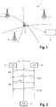
- Fig. 1 shows a schematic diagram of a first embodiment of a system 1 according to the present disclosure.
- the system 1 particularly comprises a client device 2 and at least three network devices 3, 4, 5 connected through a network.
- the location of the client device 2 shall be determined, which is particularly challenging in indoor scenarios (e.g. in a shopping mall, a train station, a sports arena, a concert hall, etc.).
- determining the location may be understood as determining the absolute position (e.g. with GPS coordinates) and/or the relative position (e.g. within as close environment and/or relative to fixed orientation points such as the network devices).
- the client device 2 may be any mobile device, whose location shall be determined and which is able to at least listen to messages exchanged between the network devices 3, 4, 5.
- Examples of such a client device 2 are a mobile station, such as a smartphone, a tablet, a laptop, a WiFi / WLAN enabled device.
- the client device 2 may also be able to communicate with other client devices and/or with one or more network devices 3, 4, 5 within the same network or with external devices, e.g. being part of another network.
- the network may be any network enabling wireless transmission of messages, such as any WiFi (WLAN) network, any communications network (e.g. 3GPP, UMTS, LTE, etc.), Bluetooth, Zigbee, or any microcell network.
- WiFi Wireless Fidelity
- communications network e.g. 3GPP, UMTS, LTE, etc.
- Bluetooth e.g., Zigbee, or any microcell network.
- the network devices 3, 4, 5 may generally be any devices that are able to communicate (i.e. transmit and receive messages) over the network. Examples of such network devices may be routers, repeaters, access points, base stations, relay stations, WiFi / WLAN enabled devices.
- each of said network devices 3, 4, 5 has a known location (i.e. a location which is known to or can be determined by the client device 2).
- the network devices 3, 4, 5 are arranged at a fixed location, but generally may also be movable.
- the network devices 3, 4, 5 are configured to pairwise exchange messages between at least three different pairs of network devices 3, 4, 5.
- a pairwise message exchange shall be understood that two network devices (forming a pair) exchange messages.
- the three network devices 3, 4, 5 can thus be used to form three different pairs (3+4, 3+5, 4+5), which pairwise exchange messages between them (i.e. messages are exchanged between network devices 3 and 4, between network devices 3 and 5 and between network devices 4 and 5). It is, however, not required that a network device is part of more than one pair; three pairs may also be formed by more than three network devices, so that in some or all pair different network devices are used. Further, the number of pairs is not limited to three; there may be (many) more pairs than three, who pairwise exchange messages, to which the client device 2 can listen and which can be used for the determination of the location of the client device 2.
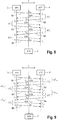
- Fig. 2 shows a network communications diagram illustrating a known method for determining the location of the client device 2' as disclosed in US 2014/0187259 A1 .
- this TDoA (time-difference-of-arrival) method considers a message exchange between two APs (AP1, AP2) 3', 4' (i.e. network devices).
- the station(s) (STA) 2' i.e. the client device(s) listen(s) to this communication only.
- the basic procedure is as follows.
- AP1 i.e. the first network device 3' broadcasts a first message M1.
- t 1 denotes the time-of-departure (ToD) of the message M1 at the antenna connector of AP1.
- Message M1 is received at AP2 (i.e. the second network device 4'), which responds with a first acknowledge message ACK1.
- This ACK1 message is received by AP1 at point in time t 4 with t 4 being the time-of-arrival (ToA) at the antenna connector of AP1.
- AP1 broadcasts a second message M2 including t 1 and t 4 to AP2, which responds with a second acknowledge message ACK2.
- the STA i.e.
- the ⁇ TOF measurement can be used for positioning using hyperbolic localization or multilateration as e.g. described in J. Figueiras and S. Frattasi, Mobile Positioning and Tracking: From Conventional to Cooperative Techniques, John Wiley & Sons, 2010 , particularly chapter 4.4.
- the method illustrated in Fig. 2 has various drawbacks. It requires one master AP (which is API in Fig. 2 ), which initiates the message exchange and broadcasts the timestamps (t 1 and t 4 in Fig. 2 ), whereby it is not defined how the master AP is determined. Further, it requires various messages (M1, M2, ACK1, ACK2 in Fig. 2 ) which are used for management but not for positioning, which causes a large data traffic overhead. Still further, it exchanges absolute timestamps (t 1 and t 4 in Fig. 2 ), which require a large amount of data bits in binary representation. Consequently, data messages containing those timestamps are rather long which results in both a huge data traffic and low positioning accuracy because of the devices' clock drift. Still further, it requires the transmission of four messages for retrieving a single positioning measurement, i.e. the efficiency is rather low. Finally, it requires a continuous message exchange between the APs so that positioning related data traffic is always present although it may be not required.
- the solution of the present disclosure considers these drawbacks and offers significant improvements. It relies on a different message exchange, which is schematically shown in a first embodiment in Fig. 3 .
- the message labeling is, as indicated in Fig. 3 , such that the k-th message Nk holds the timestamps t k (representing the time when the message Nk has been sent by the transmitting AP (network device)), t' k (representing the time when the message Nk has been received by the receiving AP (network device)) and t s,k (representing the time when the message Nk has been received by the STA (client device)).
- API broadcasts the first message N1 which is received by AP2 at ToA t' 1 .
- AP2 broadcasts the second message N2 at ToD t' 2 which is received by API at ToA t 2 .
- This message exchange may be continuously repeated as indicated in Fig. 3 .
- the content of the exchanged messages comprise ⁇ T k .
- the time information ⁇ T k may be included in the data field of the frame.
- AP and STA can obtain this information by demodulation and decoding algorithms for conventional use.
- the time resolution and maximum time which is supported is defined for the timestamp format of ⁇ T k .
- a 30bit field may be defined for ⁇ T k to define 2 30 possible timestamps (which are roughly in between 0 and 100ms in 0.1ns raster).
- the second message N2 sent by AP2 contains ⁇ T 1
- the third message N3 contains ⁇ T 2 etc. It should be noted that a message can only contain a ⁇ T k value if the AP received a message previously transmitted by the other AP. Thus, the very first message N1 within the message exchange holds no information about ⁇ T k .
- the STA(s) listen(s) to the exchanged messages Nk ( Fig. 3 depicts a single exemplary STA, but there can be more than one STAs making use of the same message exchange). In particular, the STA does not actively influence the message exchange.
- the first message N1 which has been broadcasted by API is received by the STA at ToA t S,1 (also called "time of reception” herein)
- the second message N2 sent by AP2 is received at ToA t S,2 etc.
- the STA(s) may further not only receive the pairwise exchanged messages, but may also demodulate and decode these messages to get the time difference information ⁇ T k in addition to the time of arrival of those messages.
- the STA(s) are generally not actively involved in the pairwise message exchange.
- T which is the time-of-flight (TOF) between API and AP2
- a ⁇ TOF measurement value can be obtained at every step k in steady state, i.e. after each transmission of a message Nk.
- a two-fold increase in measurement rate compared to the method known from US 2014/0187259 A1 is achieved.
- the difference between the ToA of two messages is used in the calculation of ⁇ TOF.
- the messages e.g. the messages N2 and N3 in Fig. 3 are sent asynchronously. Therefore, the equation above defining ⁇ TOF holds a correction term T+ ⁇ T k-1 , which is the period of time in between the messages (e.g. the messages N2 and N3) from AP2 and API or vice versa.
- T+ ⁇ T k-1 is the period of time in between the messages (e.g. the messages N2 and N3) from AP2 and API or vice versa.
- the transmission of the third message N3 in Fig. 3 is delayed by T+ ⁇ T 2 compared to the transmission of the second message N2.
- the disclosed TDoA positioning method requires a reference AP, i.e. the ToA of messages are referred to a dedicated AP.
- a reference AP i.e. the ToA of messages are referred to a dedicated AP.
- the subtraction is inversely performed, i.e. ToA of messages from AP2 are subtracted from ToA of messages from AP1, the sign of ⁇ TOF changes.
- the ⁇ TOF equation above features a case-by-case definition which considers the sign change.
- the ⁇ TOF measurements obtained with the equation above have always the same sign.
- the reference AP can be chosen arbitrarily, the labeling of the cases in the equation above is exemplary and can be inverted, i.e. the even label and the odd label can be interchanged. However, the labeling should be unchanged during an entire measurement period.
- the ⁇ TOF measurement values may be used for TDoA positioning using e.g. hyperbolic localization or multilateration as described in the above cited book of J. Figueiras et al., particularly chapter 4.4, which is herein incorporated by reference.
- hyperbolic localization link lengths are estimated using TDOA measurements. Since these types of measurements do not depend on the link length but on the difference between two measures of link lengths, the TDOA measurements describe a hyperbola as the possible location of the user position (which can also be seen from Fig. 1 ).
- TDOA measurements t S,i result in a difference of distances d i between APs
- B 1 2 x 2 2 + y 2 2 ⁇ x 1 2 + y 1 2 ⁇ d 2 2 x 3 2 + y 3 2 ⁇ x 1 2 + y 1 2 ⁇ d 3 2 ⁇ x 1 2 + y 1 2 ⁇ d 3 2 ⁇ x n 2 + y 1 2 ⁇ d n 2 .
- X (H T H) -1 H T B .
- the disclosed TDoA positioning method requires at least three independent ⁇ TOF measurements from different AP pairs, i.e. the measurement procedure shown in Fig. 3 is performed between at least three different AP pairs. From each different AP pair at least one ⁇ TOF measurement value is required. Therefore, each AP should to be able to communicate to each other AP and should perform a (pairwise) message exchange as depicted in Fig. 3 , wherein it is generally sufficient if a single pair of messages is exchanged between each pair of APs.
- the pairwise message exchange between the APs of the different pairs may be done alternately or (partly or fully) overlapping in time, in which case different codes and/or frequencies are preferably used by the different pairs of APs for the message exchange. If the location of the STA in 3D shall be determined, at least one ⁇ TOF measurement value is required from four different AP pairs.
- the STA can either perform the positioning itself or send the required data to an external device 6 (e.g. a location server as shown in broken lines as an option in Fig. 1 or to an entity (e.g. a computer) in a cloud)) which executes the required computations and returns the position to the STA.
- an external device 6 e.g. a location server as shown in broken lines as an option in Fig. 1 or to an entity (e.g. a computer) in a cloud
- This also holds for the evaluation of ⁇ TOF. This may help to offload computational complexity from the STA.
- the broadcast messages that indicate the AP positions are not needed if an external device 6 (e.g. the location server) is aware of the APs' positions.
- the result of the disclosed TDoA positioning method can be combined with positioning results from other methods in order to improve accuracy.
- Other methods include, for example, angular positioning methods like angle-of-departure (AoD) and/or angle-of-arrival (AoA) of the wireless signal or the known FTM.
- AoD angle-of-departure
- AoA angle-of-arrival
- the accuracy of the disclosed TDoA positioning estimates improves the more accurate and the smaller the ⁇ T k measurements are. In the latter case, accuracy is improved because the inherent time-drift of the internal clocks of the APs and the STA(s) has less influence on the position estimate.
- the APs can actively influence the positioning accuracy likewise. If the APs broadcast an altered ⁇ T* k ⁇ ⁇ T k , the positioning estimate deteriorates. Similarly, the APs can choose ⁇ T k to be large.
- Fig. 4 shows a schematic diagram of a client device 2 according to the present disclosure
- Fig. 5 shows a schematic diagram of a network device 3 (the network device 4, 5 are similar or identical) according to the present disclosure.
- the client device 2 e.g. a smartphone, comprises a receiving unit 20 configured to receive messages exchanged in a pairwise message exchange between at least three different pairs of network devices of said at least three network devices and to record the time of reception of said messages.
- the receiving unit may e.g. comprise an antenna and necessary electronics for signal reception in the wireless network, e.g. a WiFi / WLAN antenna, RF antenna, etc.
- the client device 2 comprises a location determination unit 21 configured to determine the location of the client device 2 from the known locations of the network devices of the at least three different pairs of network devices, the time difference information carried in pairwise exchanged messages between said at least three different pairs of network devices and the recorded times of reception of the pairwise exchanged messages.
- a communication interface 22 may be provided for communication with an external device (6 in Fig. 1 , e.g. a location server) to communicate the required data for calculating the location of the client device 2 to the external device 6 and to receive the calculated location from the external device 6.
- an external device (6 in Fig. 1 , e.g. a location server) to communicate the required data for calculating the location of the client device 2 to the external device 6 and to receive the calculated location from the external device 6.
- the network device 3 comprises a receiving unit 30 configured to receive a first message transmitted from another network device, with which a pairwise message exchange is performed, and a transmission unit 31 configured to transmit a second message to the other network device, i.e. units 30, 31 to perform the disclosed pairwise message exchange with another network device.
- the receiving unit 30 and the transmission unit 31 may be a collocated antenna or a pair of antennas configured for communicating in the respective network with other network devices.
- Fig. 6 shows a second embodiment of a network communications diagram for illustrating a second embodiment of a method according to the present disclosure.
- the message Nk which is broadcasted at k, comprises ⁇ T k-3 instead of ⁇ T k-1 (e.g. N5 carries ⁇ T 2 instead of ⁇ T 4 .
- N5 carries ⁇ T 2 instead of ⁇ T 4 .
- it may be difficult to broadcast ⁇ T k-1 at k because computation of ⁇ T k-1 requires the ToD of the message which contains ⁇ T k-1 already.
- a prediction algorithm or a calibration could be used.
- the insertion of a delay as shown in Fig. 6 avoids the use of such a prediction algorithm or calibration.
- the delay of ⁇ T k-1 is not limited to two as shown in Fig. 6 , but can be any even and positive number including zero.
- Fig. 7 shows a third embodiment of a network communications diagram for illustrating a third embodiment of a method according to the present disclosure.
- an optional request message R is used, which can be sent by any STA to the APs.
- This message R enables the message exchange between the APs for a certain period of time T ex .
- T ex can be either set by the APs or proposed by the STA depending on the requirements of the positioning accuracy. In the latter case, the request message R may hold the proposed value T* ex .
- Fig. 7 illustrates the proposed request message R and the subsequent message exchange.
- a STA Before a STA requests a message exchange, it is optionally required to listen to the wireless medium for a certain period of time to assure that an ongoing message and a recent upcoming message exchange is detected.
- the WLAN standard comprises several message acknowledgement (ACK) principles. Two of them can make sense in the context of the present disclosure and may be used in embodiments. According to the embodiments shown in Figs. 3 and 6 no ACK or explicit ACK is used.
- the APs respond with a message which comprises ⁇ T k and which is simultaneously an ACK that the previous message arrived.
- FIG. 7 Another embodiment of a network communications diagram for illustrating a fourth embodiment of a method according to the present disclosure using explicit ACK is shown in Fig. 7 .
- an AP transmits a (small) ACK message after each received message N, i.e. the measurement protocol is different as in Figs. 3 and 6 .
- the ACK carries no further information.
- the ToD and ToA of the ACK messages in Fig. 8 can be used to compute additional ⁇ TOF measurements as indicated in Fig. 9 showing a fifth embodiment of a network communications diagram for illustrating a fifth embodiment of a method according to the present disclosure.
- ⁇ T k,A is similar to ⁇ T k , but refers to the ToA and ToD of the ACK messages. Since the ACK messages carry no information, the k-th message comprises not only ⁇ T k but also ⁇ T k,A .
- ⁇ TOF ⁇ t S , k , A ⁇ t S , k ⁇ 1 , A ⁇ T ⁇ ⁇ T k ⁇ 1 , A k even ⁇ t S , k , A ⁇ t Sk ⁇ 1 , A ⁇ T ⁇ ⁇ T k ⁇ 1 , A k odd
- This equation may change its sign depending on the reference AP, i.e. the sign should be consistent to the labeling in the equation above.
- the measurement protocol requires no master AP. Further, almost every transmitted message contains information related to positioning, i.e. ⁇ T. Shorter message lengths are achieved since ⁇ T is a relative timestamp which requires less data bits in binary representation than absolute timestamps. Therefore, data traffic and the positioning error due to time drift are lower.
- the STA can perform positioning every k, i.e. as soon as a message has been received. Therefore, the measurement rate is increased two-fold compared to known methods. This can yield additional positioning accuracy if an appropriate averaging is applied to the measurement results.
- the STA can send a request message to the APs enabling the message exchange between the APs.
- the positioning accuracy can be determined by the APs by altering ⁇ T k and/or by keeping ⁇ T k large. In the latter case, the time drift has a stronger effect on the accuracy of the positioning estimate.
- a non-transitory machine-readable medium carrying such software such as an optical disk, a magnetic disk, semiconductor memory or the like, is also considered to represent an embodiment of the present disclosure.
- a software may also be distributed in other forms, such as via the Internet or other wired or wireless telecommunication systems.
- a circuit is a structural assemblage of electronic components including conventional circuit elements, integrated circuits including application specific integrated circuits, standard integrated circuits, application specific standard products, and field programmable gate arrays. Further a circuit includes central processing units, graphics processing units, and microprocessors which are programmed or configured according to software code. A circuit does not include pure software, although a circuit includes the above-described hardware executing software.
Landscapes
- Engineering & Computer Science (AREA)
- Physics & Mathematics (AREA)
- General Physics & Mathematics (AREA)
- Radar, Positioning & Navigation (AREA)
- Remote Sensing (AREA)
- Computer Networks & Wireless Communication (AREA)
- Signal Processing (AREA)
- Mobile Radio Communication Systems (AREA)
Claims (15)
- Verfahren zur Bestimmung eines Standorts einer Client-Einrichtung in einem Drahtlosnetz, das die Client-Einrichtung und mindestens drei Netzeinrichtungen beinhaltet, wobei jede der drei Netzeinrichtungen einen bekannten Standort aufweist, wobei das Verfahren Folgendes umfasst:paarweises Austauschen von Nachrichten zwischen mindestens drei unterschiedlichen Paaren von Netzeinrichtungen der mindestens drei Netzeinrichtungen, wobei, in einem paarweisen Nachrichtenaustausch, eine erste Netzeinrichtung eine erste Nachricht überträgt und eine zweite Netzeinrichtung die erste Nachricht, die von der ersten Netzeinrichtung übertragen wird, empfängt und eine zweite Nachricht zu der ersten Netzeinrichtung überträgt, wobei die zweite Nachricht Zeitdifferenzinformationen über die Zeitdifferenz zwischen dem Empfang einer Nachricht und der anschließenden Übertragung einer Nachricht durch die zweite Netzeinrichtung beinhaltet, undBestimmen des Standorts der Client-Einrichtung aus den bekannten Standorten der Netzeinrichtungen der mindestens drei unterschiedlichen Paare von Netzeinrichtungen, den Zeitdifferenzinformationen, die in paarweise ausgetauschten Nachrichten zwischen den mindestens drei unterschiedlichen Paaren von Netzeinrichtungen geführt werden, und Zeiten des Empfangs der paarweise ausgetauschten Nachrichten durch die Client-Einrichtung,wobei, in einem paarweisen Nachrichtenaustausch, die erste Netzeinrichtung die zweite Nachricht, die von der zweiten Einrichtung übertragen wird, empfängt und eine dritte Nachricht zu der zweiten Netzeinrichtung überträgt, wobei die dritte Nachricht zweite Zeitdifferenzinformationen über die Zeitdifferenz zwischen dem Empfang einer Nachricht und der anschließenden Übertragung einer Nachricht durch die erste Netzeinrichtung beinhaltet.
- Verfahren nach Anspruch 1,
wobei die Zeiten des Empfangs der jeweiligen ersten und zweiten Nachricht durch die Client-Einrichtung bei der Bestimmung des Standorts der Client-Einrichtung verwendet werden. - Verfahren nach einem vorangegangenen Anspruch,
wobei die Laufzeit zwischen den jeweiligen zwei Netzeinrichtungen eines Paares von Netzeinrichtungen, die einen paarweisen Nachrichtenaustausch durchführen, bei der Bestimmung des Standorts der Client-Einrichtung verwendet wird. - Verfahren nach einem vorangegangenen Anspruch, ferner umfassend:Berechnen, pro Paar von Netzeinrichtungen, die einen paarweisen Nachrichtenaustausch durchführen, von mindestens einem differenziellen Laufzeitwert, wobei ein differenzieller Laufzeitwert aus einem Paar von nacheinander übertragenen Nachrichten berechnet wird, insbesondere durch Berechnen der Zeitdifferenz zwischen den Zeiten des Empfangs, zu denen die beiden Nachrichten des Paares von nacheinander übertragenen Nachrichten durch die Client-Einrichtung empfangen werden, und Subtrahieren davon der Zeitdifferenzinformationen über die Zeitdifferenz zwischen dem Empfang der ersten Nachricht und der Übertragung der zweiten Nachricht des Paares von Nachrichten, undVerwenden des mindestens einen differenziellen Laufzeitwerts bei der Bestimmung des Standorts der Client-Einrichtung.
- Verfahren nach Anspruch 4,
ferner umfassend Subtrahieren, von der berechneten Zeitdifferenz zwischen den Zeiten des Empfangs, der Laufzeit zwischen den jeweiligen zwei Netzeinrichtungen eines Paares von Netzeinrichtungen, die einen paarweisen Nachrichtenaustausch durchführen, um den differenziellen Laufzeitwert zu erhalten. - Verfahren nach einem vorangegangenen Anspruch,
wobei der Standort der Client-Einrichtung unter Verwendung eines Triangulationsverfahrens, eines hyperbolischen Lokalisierungsverfahrens oder eines Multilaterationverfahrens bestimmt wird. - Verfahren nach einem vorangegangenen Anspruch,
wobei Zeitdifferenzinformationen, die in einer Nachricht geführt werden, die Zeitdifferenz zwischen der letzten empfangenen Nachricht und der anschließenden Übertragung einer Nachricht und/oder zwischen einer früheren empfangenen Nachricht und der direkt anschließenden Übertragung einer Nachricht angeben. - Verfahren nach einem vorangegangenen Anspruch,
wobei der paarweise Austausch von Nachrichten kontinuierlich, mit regelmäßigen Intervallen oder auf Anforderung der Client-Einrichtung durchgeführt wird. - Verfahren nach einem vorangegangenen Anspruch,
wobei, in dem paarweisen Nachrichtenaustausch, die erste Netzeinrichtung zusätzlich eine erste Bestätigungsnachricht überträgt und die zweite Netzeinrichtung zusätzlich die erste Bestätigungsnachricht, die von der ersten Netzeinrichtung übertragen wird, empfängt und eine zweite Bestätigungsnachricht zu der ersten Netzeinrichtung überträgt, wobei die zweite Nachricht zusätzlich Bestätigungszeitdifferenzinformationen über die Zeitdifferenz zwischen dem Empfang einer Bestätigungsnachricht und der anschließenden Übertragung einer Bestätigungsnachricht durch die zweite Netzeinrichtung beinhaltet,
wobei die erste Bestätigungszeitdifferenz zusätzlich bei der Bestimmung des Standorts der Client-Einrichtung verwendet wird. - System zur Bestimmung eines Standorts einer Client-Einrichtung in einem Drahtlosnetz, wobei das System Folgendes umfasst:eine Client-Einrichtung undmindestens drei Netzeinrichtungen, wobei jede der drei Netzeinrichtungen einem bekannten Standort aufweist, die ausgelegt sind zum paarweisen Austauschen von Nachrichten zwischen mindestens drei unterschiedlichen Paaren von Netzeinrichtungen der mindestens drei Netzeinrichtungen, wobei, in einem paarweisen Nachrichtenaustausch, eine erste Netzeinrichtung eine erste Nachricht überträgt und eine zweite Netzeinrichtung die erste Nachricht, die von der ersten Netzeinrichtung übertragen wird, empfängt und eine zweite Nachricht zu der ersten Netzeinrichtung überträgt, wobei die zweite Nachricht Zeitdifferenzinformationen über die Zeitdifferenz zwischen dem Empfang einer Nachricht und der anschließenden Übertragung einer Nachricht durch die zweite Netzeinrichtung beinhaltet,wobei die Client-Einrichtung oder eine externe Einrichtung, die mit der Client-Einrichtung gekoppelt ist, dazu ausgelegt ist, den Standort der Client-Einrichtung aus den bekannten Standorten der Netzeinrichtungen der mindestens drei unterschiedlichen Paare von Netzeinrichtungen, den Zeitdifferenzinformationen, die in paarweise ausgetauschten Nachrichten zwischen den mindestens drei unterschiedlichen Paaren von Netzeinrichtungen geführt werden, und Zeiten des Empfangs der paarweise ausgetauschten Nachrichten durch die Client-Einrichtung zu bestimmen, undwobei, in einem paarweisen Nachrichtenaustausch, die erste Netzeinrichtung die zweite Nachricht, die von der zweiten Netzeinrichtung übertragen wird, empfängt und eine dritte Nachricht zu der zweiten Netzeinrichtung überträgt, wobei die dritte Nachricht zweite Zeitdifferenzinformationen über die Zeitdifferenz zwischen dem Empfang einer Nachricht und der anschließenden Übertragung einer Nachricht durch die erste Netzeinrichtung beinhaltet.
- Client-Einrichtung, die dazu ausgelegt ist, ihren Standort in einem Drahtlosnetz zu bestimmen, das die Client-Einrichtung und mindestens drei Netzeinrichtungen beinhaltet, wobei jede der drei Netzeinrichtungen einen bekannten Standort aufweist, wobei die Client-Einrichtung Folgendes umfasst:eine Empfangseinheit, die ausgelegt ist zum Empfangen von Nachrichten, die in einem paarweisen Nachrichtenaustausch zwischen mindestens drei unterschiedlichen Paaren von Netzeinrichtungen der mindestens drei Netzeinrichtungen ausgetauscht werden, und Aufzeichnen der Zeit des Empfangs der Nachrichten, wobei, in einem paarweisen Nachrichtenaustausch, eine erste Netzeinrichtung eine erste Nachricht überträgt und eine zweite Netzeinrichtung die erste Nachricht, die von der ersten Netzeinrichtung übertragen wird, empfängt und eine zweite Nachricht zu der ersten Netzeinrichtung überträgt, wobei die zweite Nachricht Zeitdifferenzinformationen über die Zeitdifferenz zwischen dem Empfang einer Nachricht und der anschließenden Übertragung einer Nachricht durch die zweite Netzeinrichtung beinhaltet, undwobei, in dem paarweisen Nachrichtenaustausch, die erste Netzeinrichtung die zweite Nachricht, die von der zweiten Netzeinrichtung übertragen wird, empfängt und eine dritte Nachricht zu der zweiten Netzeinrichtung überträgt, wobei die dritte Nachricht zweite Zeitdifferenzinformationen über die Zeitdifferenz zwischen dem Empfang einer Nachricht und der anschließenden Übertragung einer Nachricht durch die erste Netzeinrichtung beinhaltet, undeine Standortbestimmungseinheit, die ausgelegt ist zum Bestimmen des Standorts der Client-Einrichtung aus den bekannten Standorten der Netzeinrichtungen der mindestens drei unterschiedlichen Paare von Netzeinrichtungen, den Zeitdifferenzinformationen, die in paarweise ausgetauschten Nachrichten zwischen den mindestens drei unterschiedlichen Paaren von Netzeinrichtungen geführt werden, und den aufgezeichneten Zeiten des Empfangs der paarweise ausgetauschten Nachrichten.
- Standortbestimmungsverfahren zur Bestimmung des Standorts einer Client-Einrichtung in einem Drahtlosnetz, das die Client-Einrichtung und mindestens drei Netzeinrichtungen beinhaltet, wobei jede der drei Netzeinrichtungen einen bekannten Standort aufweist, wobei das Verfahren Folgendes umfasst:Empfangen von Nachrichten, die in einem paarweisen Nachrichtenaustausch zwischen mindestens drei unterschiedlichen Paaren von Netzeinrichtungen der mindestens drei Netzeinrichtungen ausgetauscht werden, und Aufzeichnen der Zeit des Empfangs der Nachrichten, wobei, in einem paarweisen Nachrichtenaustausch, eine erste Netzeinrichtung eine erste Nachricht überträgt und eine zweite Netzeinrichtung die erste Nachricht, die von der ersten Netzeinrichtung übertragen wird, empfängt und eine zweite Nachricht zu der ersten Netzeinrichtung überträgt, wobei die zweite Nachricht Zeitdifferenzinformationen über die Zeitdifferenz zwischen dem Empfang einer Nachricht und der anschließenden Übertragung einer Nachricht durch die zweite Netzeinrichtung beinhaltet, und wobei, in dem paarweisen Nachrichtenaustausch, die erste Netzeinrichtung die zweite Nachricht, die vor der zweiten Netzeinrichtung übertragen wird, empfängt und eine dritte Nachricht zu der zweiten Netzeinrichtung überträgt, wobei die dritte Nachricht zweite Zeitdifferenzinformationen über die Zeitdifferenz zwischen dem Empfang einer Nachricht und der anschließenden Übertragung einer Nachricht durch die erste Netzeinrichtung beinhaltet, undBestimmen des Standorts der Client-Einrichtung aus den bekannten Standorten der Netzeinrichtungen der mindestens drei unterschiedlichen Paare von Netzeinrichtungen, den Zeitdifferenzinformationen, die in paarweise ausgetauschten Nachrichten zwischen den mindestens drei unterschiedlichen Paaren von Netzeinrichtungen geführt werden, und den aufgezeichneten Zeiten des Empfangs der paarweise ausgetauschten Nachrichten.
- Netzeinrichtung zur Verwendung in einem Drahtlosnetz, das eine Client-Einrichtung und mindestens drei Netzeinrichtungen beinhaltet, wobei jede der drei Netzeinrichtungen einen bekannten Standort aufweist, wobei die Netzeinrichtung Folgendes umfasst:eine Empfangseinheit, die ausgelegt ist zum Empfangen einer ersten Nachricht, die von einer anderen Netzeinrichtung übertragen wird, mit der ein paarweiser Nachrichtenaustausch durchgeführt wird, undeine Übertragungseinheit, die ausgelegt ist zum Übertragen einer zweiten Nachricht zu der anderen Netzeinrichtung, wobei die zweite Nachricht Zeitdifferenzinformationen über die Zeitdifferenz zwischen dem Empfang einer Nachricht und der anschließenden Übertragung einer Nachricht durch die Netzeinrichtung beinhaltet,wobei die Empfangseinheit ausgelegt ist zum Empfangen einer dritten Nachricht von der anderen Netzeinrichtung, wobei die dritte Nachricht zweite Zeitdifferenzinformationen über die Zeitdifferenz zwischen dem Empfang einer Nachricht und der anschließenden Übertragung einer Nachricht durch die andere Netzeinrichtung beinhaltet.
- Verfahren zum Betreiben einer Netzeinrichtung in einem Drahtlosnetz, das eine Client-Einrichtung und mindestens drei Netzeinrichtungen beinhaltet, wobei jede der drei Netzeinrichtungen einen bekannten Standort aufweist, wobei das Verfahren Folgendes umfasst:Empfangen einer ersten Nachricht, die von einer anderen Netzeinrichtung übertragen wird, mit der ein paarweiser Nachrichtenaustausch durch die Netzeinrichtung durchgeführt wird,Übertragen einer zweiten Nachricht zu der anderen Netzeinrichtung, wobei die zweite Nachricht erste Zeitdifferenzinformationen über die Zeitdifferenz zwischen dem Empfang einer Nachricht und der anschließenden Übertragung einer Nachricht durch die Netzeinrichtung beinhaltet, undEmpfangen einer dritten Nachricht von der anderen Netzeinrichtung, wobei die dritte Nachricht zweite Zeitdifferenzinformationen über die Zeitdifferenz zwischen dem Empfang einer Nachricht und der anschließenden Übertragung einer Nachricht durch die andere Netzeinrichtung beinhaltet.
- Computerprogramm, das Programmcodemittel umfasst, um zu bewirken, dass ein Computer die Schritte des Verfahrens nach einem der Ansprüche 1 bis 9, 12, 14 durchführt, wenn das Computerprogramm auf einem Computer ausgeführt wird.
Priority Applications (1)
| Application Number | Priority Date | Filing Date | Title |
|---|---|---|---|
| EP19174263.4A EP3544343B1 (de) | 2015-06-25 | 2016-06-23 | Verfahren und system zur ortung eines benutzererät, eine benutzergerät und ein netzwerkgerät |
Applications Claiming Priority (2)
| Application Number | Priority Date | Filing Date | Title |
|---|---|---|---|
| EP15173758 | 2015-06-25 | ||
| PCT/EP2016/064568 WO2016207297A1 (en) | 2015-06-25 | 2016-06-23 | Method and system for determining a location of a client device, a client device apparatus and a network device apparatus |
Related Child Applications (1)
| Application Number | Title | Priority Date | Filing Date |
|---|---|---|---|
| EP19174263.4A Division EP3544343B1 (de) | 2015-06-25 | 2016-06-23 | Verfahren und system zur ortung eines benutzererät, eine benutzergerät und ein netzwerkgerät |
Publications (2)
| Publication Number | Publication Date |
|---|---|
| EP3314964A1 EP3314964A1 (de) | 2018-05-02 |
| EP3314964B1 true EP3314964B1 (de) | 2019-05-15 |
Family
ID=53510623
Family Applications (2)
| Application Number | Title | Priority Date | Filing Date |
|---|---|---|---|
| EP16732585.1A Not-in-force EP3314964B1 (de) | 2015-06-25 | 2016-06-23 | Verfahren und system zur ortung eines benutzergerätes, ein benutzergerät und ein netzwerkgerät |
| EP19174263.4A Not-in-force EP3544343B1 (de) | 2015-06-25 | 2016-06-23 | Verfahren und system zur ortung eines benutzererät, eine benutzergerät und ein netzwerkgerät |
Family Applications After (1)
| Application Number | Title | Priority Date | Filing Date |
|---|---|---|---|
| EP19174263.4A Not-in-force EP3544343B1 (de) | 2015-06-25 | 2016-06-23 | Verfahren und system zur ortung eines benutzererät, eine benutzergerät und ein netzwerkgerät |
Country Status (3)
| Country | Link |
|---|---|
| US (2) | US10416279B2 (de) |
| EP (2) | EP3314964B1 (de) |
| WO (1) | WO2016207297A1 (de) |
Families Citing this family (7)
| Publication number | Priority date | Publication date | Assignee | Title |
|---|---|---|---|---|
| JP7000576B2 (ja) | 2017-12-21 | 2022-01-19 | オカド・イノベーション・リミテッド | 位置決めデバイス、通信システム及び方法 |
| ES2858366T3 (es) * | 2018-04-11 | 2021-09-30 | Teknologian Tutkimuskeskus Vtt Oy | Posicionamiento inalámbrico |
| KR102708411B1 (ko) * | 2019-06-17 | 2024-09-23 | 엘지전자 주식회사 | Nr v2x에서 사이드링크 rtt를 이용한 포지셔닝 방법 및 장치 |
| US12279226B2 (en) | 2019-12-06 | 2025-04-15 | Sony Semiconductor Solutions Corporation | Communication device and method |
| US11743858B2 (en) * | 2020-09-21 | 2023-08-29 | Samsung Electronics Co., Ltd. | System and method of optimizing wireless device ranging |
| CN116962964A (zh) * | 2022-04-20 | 2023-10-27 | 华为技术有限公司 | 一种定位方法及通信装置 |
| US12411202B2 (en) | 2022-12-14 | 2025-09-09 | Cisco Technology, Inc. | Estimating position from reference signals received by coordinating access points |
Family Cites Families (16)
| Publication number | Priority date | Publication date | Assignee | Title |
|---|---|---|---|---|
| WO2004052027A2 (en) * | 2002-11-27 | 2004-06-17 | Cognio, Inc | System and method for locating sources of unknown wireless radio signals |
| EP1701564A4 (de) * | 2003-12-10 | 2012-11-07 | Nec Corp | Übertragungszeitdifferenz-messverfahren und system dafür |
| US8837530B2 (en) * | 2010-03-12 | 2014-09-16 | University Of Maryland | Method and system for adaptive synchronization of timing information generated by independently clocked communication nodes |
| WO2011160697A1 (en) * | 2010-06-25 | 2011-12-29 | Innovationszentrum für Telekommunikationstechnik GmbH IZT | Method and system for determining a time difference, method and system for finding a position of a transmitter |
| EP2798367B1 (de) * | 2011-12-28 | 2018-02-28 | Aeroscout Ltd | Verfahren und systeme zur lokalisierung von vorrichtungen |
| WO2014099030A1 (en) | 2012-12-18 | 2014-06-26 | Intel Corporation | Wireless station and methods for tof positioning using reverse-direction grant |
| US9213093B2 (en) * | 2012-12-21 | 2015-12-15 | Qualcomm Incorporated | Pairwise measurements for improved position determination |
| US10039073B2 (en) | 2013-01-03 | 2018-07-31 | Qualcomm Incorporated | Method for determining location of wireless devices |
| US9125168B2 (en) | 2013-01-23 | 2015-09-01 | Intel Corporation | Polled time-of-flight response |
| US20140233550A1 (en) * | 2013-02-18 | 2014-08-21 | Apple Inc. | Location determination |
| US9661603B2 (en) | 2013-08-30 | 2017-05-23 | Qualcomm Incorporated | Passive positioning utilizing beacon neighbor reports |
| US9288625B2 (en) * | 2014-06-30 | 2016-03-15 | Qualcomm Technologies International, Ltd. | Method for determining location of wireless devices based on information within messages received from other network devices |
| US9277369B2 (en) * | 2014-06-30 | 2016-03-01 | Qualcomm Technologies International, Ltd. | Method for determining location of wireless devices |
| US9936391B2 (en) * | 2015-01-29 | 2018-04-03 | Aruba Networks, Inc. | Method and apparatus for inferring wireless scan information without performing scanning or performing limited scanning |
| US9736640B2 (en) * | 2015-02-23 | 2017-08-15 | Qualcomm Incorporated | Methods and systems for a ranging protocol |
| US10349367B2 (en) * | 2015-03-03 | 2019-07-09 | Qualcomm Incorporated | Methods and systems for synchronizing devices |
-
2016
- 2016-06-23 EP EP16732585.1A patent/EP3314964B1/de not_active Not-in-force
- 2016-06-23 US US15/735,975 patent/US10416279B2/en active Active
- 2016-06-23 EP EP19174263.4A patent/EP3544343B1/de not_active Not-in-force
- 2016-06-23 WO PCT/EP2016/064568 patent/WO2016207297A1/en not_active Ceased
-
2019
- 2019-08-08 US US16/535,110 patent/US10852387B2/en active Active
Non-Patent Citations (1)
| Title |
|---|
| None * |
Also Published As
| Publication number | Publication date |
|---|---|
| US10416279B2 (en) | 2019-09-17 |
| US10852387B2 (en) | 2020-12-01 |
| US20200011963A1 (en) | 2020-01-09 |
| EP3544343A1 (de) | 2019-09-25 |
| EP3544343B1 (de) | 2021-11-24 |
| WO2016207297A1 (en) | 2016-12-29 |
| EP3314964A1 (de) | 2018-05-02 |
| US20180180710A1 (en) | 2018-06-28 |
Similar Documents
| Publication | Publication Date | Title |
|---|---|---|
| US10852387B2 (en) | Method and system for determining a location of a client device, a client device apparatus and a network device apparatus | |
| US10353048B2 (en) | Apparatus and method for location estimation in a wireless communication system | |
| EP2727392B1 (de) | Verteilter positionierungsmechanismus für drahtlose kommunikationsvorrichtungen | |
| US8335173B2 (en) | Inserting time of departure information in frames to support multi-channel location techniques | |
| US9726751B2 (en) | Measuring time of arrival of a signal | |
| CN105492922B (zh) | 利用往返时间信息的被动定位 | |
| US9769621B2 (en) | Positioning method for user equipment, data sending method, device and user equipment | |
| US10104635B2 (en) | Unicast and broadcast protocol for wireless local area network ranging and direction finding | |
| TWI522640B (zh) | 供頻道資訊交換飛行時間範圍判定用之系統及方法 | |
| US9288625B2 (en) | Method for determining location of wireless devices based on information within messages received from other network devices | |
| KR20170117057A (ko) | 도달 각도 및 출발 각도를 갖는 ftm 프로토콜 | |
| EP3651511A1 (de) | Verfahren und vorrichtungen zur positionierung auf basis des feedbacks von signalkorrelationsfunktionseigenschaften | |
| JP7815216B2 (ja) | 電子デバイス、及び該電子デバイスの位置情報獲得方法 | |
| US9404997B2 (en) | Communication station and method for time-of-flight positioning using cooperating stations | |
| JP7617912B2 (ja) | 測距信号を活用した車両および歩行者の測位 | |
| US10031209B2 (en) | Localization using time-of-flight | |
| WO2017113072A1 (zh) | 基于到达时间差定位方法、用户设备及网络设备 | |
| US20250081156A1 (en) | Method and apparatus for supporting ultra wideband positioning in wireless communication system | |
| CN117204071A (zh) | 终端的定位方法、装置、设备及介质 | |
| US20220413085A1 (en) | Node positioning |
Legal Events
| Date | Code | Title | Description |
|---|---|---|---|
| STAA | Information on the status of an ep patent application or granted ep patent |
Free format text: STATUS: THE INTERNATIONAL PUBLICATION HAS BEEN MADE |
|
| PUAI | Public reference made under article 153(3) epc to a published international application that has entered the european phase |
Free format text: ORIGINAL CODE: 0009012 |
|
| STAA | Information on the status of an ep patent application or granted ep patent |
Free format text: STATUS: REQUEST FOR EXAMINATION WAS MADE |
|
| 17P | Request for examination filed |
Effective date: 20180125 |
|
| AK | Designated contracting states |
Kind code of ref document: A1 Designated state(s): AL AT BE BG CH CY CZ DE DK EE ES FI FR GB GR HR HU IE IS IT LI LT LU LV MC MK MT NL NO PL PT RO RS SE SI SK SM TR |
|
| AX | Request for extension of the european patent |
Extension state: BA ME |
|
| DAV | Request for validation of the european patent (deleted) | ||
| DAX | Request for extension of the european patent (deleted) | ||
| RIC1 | Information provided on ipc code assigned before grant |
Ipc: G01S 5/08 20060101ALI20181012BHEP Ipc: H04W 84/12 20090101ALI20181012BHEP Ipc: G01S 5/14 20060101ALI20181012BHEP Ipc: G01S 11/02 20100101ALI20181012BHEP Ipc: H04W 64/00 20090101AFI20181012BHEP Ipc: G01S 5/02 20100101ALI20181012BHEP Ipc: G01S 5/10 20060101ALI20181012BHEP |
|
| GRAJ | Information related to disapproval of communication of intention to grant by the applicant or resumption of examination proceedings by the epo deleted |
Free format text: ORIGINAL CODE: EPIDOSDIGR1 |
|
| GRAP | Despatch of communication of intention to grant a patent |
Free format text: ORIGINAL CODE: EPIDOSNIGR1 |
|
| GRAP | Despatch of communication of intention to grant a patent |
Free format text: ORIGINAL CODE: EPIDOSNIGR1 |
|
| STAA | Information on the status of an ep patent application or granted ep patent |
Free format text: STATUS: GRANT OF PATENT IS INTENDED |
|
| INTG | Intention to grant announced |
Effective date: 20181207 |
|
| GRAS | Grant fee paid |
Free format text: ORIGINAL CODE: EPIDOSNIGR3 |
|
| GRAA | (expected) grant |
Free format text: ORIGINAL CODE: 0009210 |
|
| STAA | Information on the status of an ep patent application or granted ep patent |
Free format text: STATUS: THE PATENT HAS BEEN GRANTED |
|
| AK | Designated contracting states |
Kind code of ref document: B1 Designated state(s): AL AT BE BG CH CY CZ DE DK EE ES FI FR GB GR HR HU IE IS IT LI LT LU LV MC MK MT NL NO PL PT RO RS SE SI SK SM TR |
|
| REG | Reference to a national code |
Ref country code: CH Ref legal event code: EP |
|
| REG | Reference to a national code |
Ref country code: DE Ref legal event code: R096 Ref document number: 602016014040 Country of ref document: DE |
|
| REG | Reference to a national code |
Ref country code: IE Ref legal event code: FG4D |
|
| REG | Reference to a national code |
Ref country code: NL Ref legal event code: FP |
|
| REG | Reference to a national code |
Ref country code: LT Ref legal event code: MG4D |
|
| PG25 | Lapsed in a contracting state [announced via postgrant information from national office to epo] |
Ref country code: AL Free format text: LAPSE BECAUSE OF FAILURE TO SUBMIT A TRANSLATION OF THE DESCRIPTION OR TO PAY THE FEE WITHIN THE PRESCRIBED TIME-LIMIT Effective date: 20190515 Ref country code: ES Free format text: LAPSE BECAUSE OF FAILURE TO SUBMIT A TRANSLATION OF THE DESCRIPTION OR TO PAY THE FEE WITHIN THE PRESCRIBED TIME-LIMIT Effective date: 20190515 Ref country code: HR Free format text: LAPSE BECAUSE OF FAILURE TO SUBMIT A TRANSLATION OF THE DESCRIPTION OR TO PAY THE FEE WITHIN THE PRESCRIBED TIME-LIMIT Effective date: 20190515 Ref country code: NO Free format text: LAPSE BECAUSE OF FAILURE TO SUBMIT A TRANSLATION OF THE DESCRIPTION OR TO PAY THE FEE WITHIN THE PRESCRIBED TIME-LIMIT Effective date: 20190815 Ref country code: PT Free format text: LAPSE BECAUSE OF FAILURE TO SUBMIT A TRANSLATION OF THE DESCRIPTION OR TO PAY THE FEE WITHIN THE PRESCRIBED TIME-LIMIT Effective date: 20190915 Ref country code: SE Free format text: LAPSE BECAUSE OF FAILURE TO SUBMIT A TRANSLATION OF THE DESCRIPTION OR TO PAY THE FEE WITHIN THE PRESCRIBED TIME-LIMIT Effective date: 20190515 Ref country code: FI Free format text: LAPSE BECAUSE OF FAILURE TO SUBMIT A TRANSLATION OF THE DESCRIPTION OR TO PAY THE FEE WITHIN THE PRESCRIBED TIME-LIMIT Effective date: 20190515 Ref country code: LT Free format text: LAPSE BECAUSE OF FAILURE TO SUBMIT A TRANSLATION OF THE DESCRIPTION OR TO PAY THE FEE WITHIN THE PRESCRIBED TIME-LIMIT Effective date: 20190515 |
|
| PG25 | Lapsed in a contracting state [announced via postgrant information from national office to epo] |
Ref country code: RS Free format text: LAPSE BECAUSE OF FAILURE TO SUBMIT A TRANSLATION OF THE DESCRIPTION OR TO PAY THE FEE WITHIN THE PRESCRIBED TIME-LIMIT Effective date: 20190515 Ref country code: LV Free format text: LAPSE BECAUSE OF FAILURE TO SUBMIT A TRANSLATION OF THE DESCRIPTION OR TO PAY THE FEE WITHIN THE PRESCRIBED TIME-LIMIT Effective date: 20190515 Ref country code: BG Free format text: LAPSE BECAUSE OF FAILURE TO SUBMIT A TRANSLATION OF THE DESCRIPTION OR TO PAY THE FEE WITHIN THE PRESCRIBED TIME-LIMIT Effective date: 20190815 Ref country code: GR Free format text: LAPSE BECAUSE OF FAILURE TO SUBMIT A TRANSLATION OF THE DESCRIPTION OR TO PAY THE FEE WITHIN THE PRESCRIBED TIME-LIMIT Effective date: 20190816 |
|
| REG | Reference to a national code |
Ref country code: AT Ref legal event code: MK05 Ref document number: 1134880 Country of ref document: AT Kind code of ref document: T Effective date: 20190515 |
|
| PG25 | Lapsed in a contracting state [announced via postgrant information from national office to epo] |
Ref country code: AT Free format text: LAPSE BECAUSE OF FAILURE TO SUBMIT A TRANSLATION OF THE DESCRIPTION OR TO PAY THE FEE WITHIN THE PRESCRIBED TIME-LIMIT Effective date: 20190515 Ref country code: DK Free format text: LAPSE BECAUSE OF FAILURE TO SUBMIT A TRANSLATION OF THE DESCRIPTION OR TO PAY THE FEE WITHIN THE PRESCRIBED TIME-LIMIT Effective date: 20190515 Ref country code: SK Free format text: LAPSE BECAUSE OF FAILURE TO SUBMIT A TRANSLATION OF THE DESCRIPTION OR TO PAY THE FEE WITHIN THE PRESCRIBED TIME-LIMIT Effective date: 20190515 Ref country code: EE Free format text: LAPSE BECAUSE OF FAILURE TO SUBMIT A TRANSLATION OF THE DESCRIPTION OR TO PAY THE FEE WITHIN THE PRESCRIBED TIME-LIMIT Effective date: 20190515 Ref country code: CZ Free format text: LAPSE BECAUSE OF FAILURE TO SUBMIT A TRANSLATION OF THE DESCRIPTION OR TO PAY THE FEE WITHIN THE PRESCRIBED TIME-LIMIT Effective date: 20190515 |
|
| REG | Reference to a national code |
Ref country code: CH Ref legal event code: PL |
|
| REG | Reference to a national code |
Ref country code: DE Ref legal event code: R097 Ref document number: 602016014040 Country of ref document: DE |
|
| PG25 | Lapsed in a contracting state [announced via postgrant information from national office to epo] |
Ref country code: MC Free format text: LAPSE BECAUSE OF FAILURE TO SUBMIT A TRANSLATION OF THE DESCRIPTION OR TO PAY THE FEE WITHIN THE PRESCRIBED TIME-LIMIT Effective date: 20190515 Ref country code: SM Free format text: LAPSE BECAUSE OF FAILURE TO SUBMIT A TRANSLATION OF THE DESCRIPTION OR TO PAY THE FEE WITHIN THE PRESCRIBED TIME-LIMIT Effective date: 20190515 Ref country code: IT Free format text: LAPSE BECAUSE OF FAILURE TO SUBMIT A TRANSLATION OF THE DESCRIPTION OR TO PAY THE FEE WITHIN THE PRESCRIBED TIME-LIMIT Effective date: 20190515 |
|
| PLBE | No opposition filed within time limit |
Free format text: ORIGINAL CODE: 0009261 |
|
| STAA | Information on the status of an ep patent application or granted ep patent |
Free format text: STATUS: NO OPPOSITION FILED WITHIN TIME LIMIT |
|
| REG | Reference to a national code |
Ref country code: BE Ref legal event code: MM Effective date: 20190630 |
|
| PG25 | Lapsed in a contracting state [announced via postgrant information from national office to epo] |
Ref country code: TR Free format text: LAPSE BECAUSE OF FAILURE TO SUBMIT A TRANSLATION OF THE DESCRIPTION OR TO PAY THE FEE WITHIN THE PRESCRIBED TIME-LIMIT Effective date: 20190515 |
|
| 26N | No opposition filed |
Effective date: 20200218 |
|
| PG25 | Lapsed in a contracting state [announced via postgrant information from national office to epo] |
Ref country code: PL Free format text: LAPSE BECAUSE OF FAILURE TO SUBMIT A TRANSLATION OF THE DESCRIPTION OR TO PAY THE FEE WITHIN THE PRESCRIBED TIME-LIMIT Effective date: 20190515 Ref country code: IE Free format text: LAPSE BECAUSE OF NON-PAYMENT OF DUE FEES Effective date: 20190623 |
|
| PG25 | Lapsed in a contracting state [announced via postgrant information from national office to epo] |
Ref country code: BE Free format text: LAPSE BECAUSE OF NON-PAYMENT OF DUE FEES Effective date: 20190630 Ref country code: SI Free format text: LAPSE BECAUSE OF FAILURE TO SUBMIT A TRANSLATION OF THE DESCRIPTION OR TO PAY THE FEE WITHIN THE PRESCRIBED TIME-LIMIT Effective date: 20190515 Ref country code: CH Free format text: LAPSE BECAUSE OF NON-PAYMENT OF DUE FEES Effective date: 20190630 Ref country code: LU Free format text: LAPSE BECAUSE OF NON-PAYMENT OF DUE FEES Effective date: 20190623 Ref country code: LI Free format text: LAPSE BECAUSE OF NON-PAYMENT OF DUE FEES Effective date: 20190630 |
|
| PG25 | Lapsed in a contracting state [announced via postgrant information from national office to epo] |
Ref country code: FR Free format text: LAPSE BECAUSE OF NON-PAYMENT OF DUE FEES Effective date: 20190715 |
|
| GBPC | Gb: european patent ceased through non-payment of renewal fee |
Effective date: 20200623 |
|
| PG25 | Lapsed in a contracting state [announced via postgrant information from national office to epo] |
Ref country code: RO Free format text: LAPSE BECAUSE OF FAILURE TO SUBMIT A TRANSLATION OF THE DESCRIPTION OR TO PAY THE FEE WITHIN THE PRESCRIBED TIME-LIMIT Effective date: 20190515 Ref country code: GB Free format text: LAPSE BECAUSE OF NON-PAYMENT OF DUE FEES Effective date: 20200623 |
|
| PG25 | Lapsed in a contracting state [announced via postgrant information from national office to epo] |
Ref country code: CY Free format text: LAPSE BECAUSE OF FAILURE TO SUBMIT A TRANSLATION OF THE DESCRIPTION OR TO PAY THE FEE WITHIN THE PRESCRIBED TIME-LIMIT Effective date: 20190515 |
|
| PG25 | Lapsed in a contracting state [announced via postgrant information from national office to epo] |
Ref country code: IS Free format text: LAPSE BECAUSE OF FAILURE TO SUBMIT A TRANSLATION OF THE DESCRIPTION OR TO PAY THE FEE WITHIN THE PRESCRIBED TIME-LIMIT Effective date: 20190915 |
|
| PG25 | Lapsed in a contracting state [announced via postgrant information from national office to epo] |
Ref country code: MT Free format text: LAPSE BECAUSE OF FAILURE TO SUBMIT A TRANSLATION OF THE DESCRIPTION OR TO PAY THE FEE WITHIN THE PRESCRIBED TIME-LIMIT Effective date: 20190515 Ref country code: HU Free format text: LAPSE BECAUSE OF FAILURE TO SUBMIT A TRANSLATION OF THE DESCRIPTION OR TO PAY THE FEE WITHIN THE PRESCRIBED TIME-LIMIT; INVALID AB INITIO Effective date: 20160623 |
|
| PG25 | Lapsed in a contracting state [announced via postgrant information from national office to epo] |
Ref country code: MK Free format text: LAPSE BECAUSE OF FAILURE TO SUBMIT A TRANSLATION OF THE DESCRIPTION OR TO PAY THE FEE WITHIN THE PRESCRIBED TIME-LIMIT Effective date: 20190515 |
|
| P01 | Opt-out of the competence of the unified patent court (upc) registered |
Effective date: 20230527 |
|
| PGFP | Annual fee paid to national office [announced via postgrant information from national office to epo] |
Ref country code: NL Payment date: 20230523 Year of fee payment: 8 Ref country code: DE Payment date: 20230523 Year of fee payment: 8 |
|
| REG | Reference to a national code |
Ref country code: DE Ref legal event code: R119 Ref document number: 602016014040 Country of ref document: DE |
|
| REG | Reference to a national code |
Ref country code: NL Ref legal event code: MM Effective date: 20240701 |
|
| PG25 | Lapsed in a contracting state [announced via postgrant information from national office to epo] |
Ref country code: NL Free format text: LAPSE BECAUSE OF NON-PAYMENT OF DUE FEES Effective date: 20240701 |
|
| PG25 | Lapsed in a contracting state [announced via postgrant information from national office to epo] |
Ref country code: NL Free format text: LAPSE BECAUSE OF NON-PAYMENT OF DUE FEES Effective date: 20240701 |
|
| PG25 | Lapsed in a contracting state [announced via postgrant information from national office to epo] |
Ref country code: DE Free format text: LAPSE BECAUSE OF NON-PAYMENT OF DUE FEES Effective date: 20250101 |