EP3315260A1 - Machine à clouer - Google Patents
Machine à clouer Download PDFInfo
- Publication number
- EP3315260A1 EP3315260A1 EP16813539.0A EP16813539A EP3315260A1 EP 3315260 A1 EP3315260 A1 EP 3315260A1 EP 16813539 A EP16813539 A EP 16813539A EP 3315260 A1 EP3315260 A1 EP 3315260A1
- Authority
- EP
- European Patent Office
- Prior art keywords
- cylinder
- striker
- piston
- nailing machine
- pawl
- Prior art date
- Legal status (The legal status is an assumption and is not a legal conclusion. Google has not performed a legal analysis and makes no representation as to the accuracy of the status listed.)
- Granted
Links
Images


Classifications
-
- B—PERFORMING OPERATIONS; TRANSPORTING
- B25—HAND TOOLS; PORTABLE POWER-DRIVEN TOOLS; MANIPULATORS
- B25C—HAND-HELD NAILING OR STAPLING TOOLS; MANUALLY OPERATED PORTABLE STAPLING TOOLS
- B25C1/00—Hand-held nailing tools; Nail feeding devices
- B25C1/04—Hand-held nailing tools; Nail feeding devices operated by fluid pressure, e.g. by air pressure
- B25C1/047—Mechanical details
-
- B—PERFORMING OPERATIONS; TRANSPORTING
- B25—HAND TOOLS; PORTABLE POWER-DRIVEN TOOLS; MANIPULATORS
- B25C—HAND-HELD NAILING OR STAPLING TOOLS; MANUALLY OPERATED PORTABLE STAPLING TOOLS
- B25C1/00—Hand-held nailing tools; Nail feeding devices
- B25C1/06—Hand-held nailing tools; Nail feeding devices operated by electric power
Definitions
- the present invention pertains to the technical field of machine manufacturing, and more particularly to a nailing device, specifically, a nailing machine.
- a nailing machine that is a nail gun includes electric nail gun, pneumatic nail gun, gas nail gun, manual nail gun, and so on.
- a pneumatic nail gun is also known as pneumatic nailing machine.
- the existing pneumatic nailing machines mostly use the pneumatic pump, generating the air pressure to push the striker, as the power source. High pressure gas drives the striker in the cylinder of the nailing machine to execute the hammering motion, driving nails from the strip nails into the object, or shooting the nails out.
- the nail gun body assembly is composed of a gun body, a cylinder, a balancing valve, a trigger assembly, a striker assembly, a cushion, a gun muzzle, and a gun groove.
- the nailing machine magazine assembly consists of the gun head, gun cover, fixed magazine, replaceable magazine, and other accessories. Through the action of the compression spring or tension spring, the nail will be sent into the gun cover groove. When the striker egresses the nozzle, a nail shoots out.
- Chinese patent discloses a pneumatic nailing device, consisting of nail feeding system, cover, cover screws, press block, press block screws, and striker.
- the upper end of the nail feeding system is provided with a nail passage.
- the striker is arranged in the nail passage.
- the cover and the press block is arranged above the nail passage.
- the striker can move within the nail passage.
- the cover is provided with a through hole.
- the upper end of the nail feeding system is provided with cover screw threaded holes. Through holes are provided with cover screws. The cover screws pass through the through holes, and are tighten within the cover screw threaded holes.
- the cover is provided with a magnet hole. A magnet is provided in the magnet hole.
- the above patent does not disclose a specific nail feeding system structure, while the air compressor used in the prior art, generating the air pressure to push the striker, is adopted as the power source. Structure wise, it is more bulky, also the continuous efficiency of firing the striker cannot be guaranteed.
- One objective of one embodiment of the present invention addresses the above problems of the prior art, a nailing machine is provided.
- the technical problem to be solved by one embodiment of the present invention is how to reduce the volume and weight of the nailing machine and ensure that the nailing machine can continuously and efficiently fire.
- a nailing machine characterized in that, the nailing machine includes a first cylinder and a second cylinder disposed outside the first cylinder.
- the working chamber of the first cylinder and the working chamber of the second cylinder communicate with each other.
- the first cylinder has a first piston within and the first piston is fixedly connected with a striker.
- the striker has a locking part.
- the nailing machine also includes a pawl.
- a second piston is arranged in the second cylinder, and a second piston is reciprocated between a first position and a second position of the second cylinder by a motor.
- the striker is locked at the locking part of the striker by the pawl.
- the motor drives the pawl to disengage from the locking part.
- the working principle is as follows.
- the nailing machine reciprocates the second piston in the second cylinder through the motor.
- the second piston can reach the two extreme points, at the first position and the second position.
- the second cylinder has a negative pressure generated within and, due to the mutual communication between the first cylinder and the second cylinder, sucks the first piston, and moves the first piston inward.
- the striker also retracts inward to the first cylinder.
- the motor drives the second piston for the next stroke.
- the second piston moves to the second position. High pressure is generated in the first cylinder and the second cylinder.
- the nailing machine is also often used in conjunction with a nail storage magazine. Strip nails are placed inside the magazine, with the first nail in the strip nails opposite to the striker. By the impact of the striker, the nail is nailed into an object or the nail shoots out. This nailing machine needs no extra air pump, only a power supply, resulting a reduced space requirement.
- the motor drives the second piston to compress air and also drives the pawl to achieve the rapid and continuous firing of strip nails.
- the motor is a DC motor.
- a hinge axle is provided on_the rotating shaft of the motor and the hinge axle is capable of rotating circumferentially about the axis of the rotating shaft of the motor, the hinge axle is pivot connected with a rod connected with the second piston.
- One end of the rod is pivotally connected to the hinge axle.
- the other end is hinged on the second piston.
- one end of the rod is pivotally connected to the hinge axle.
- the other end is connected to the second piston through a universal joint or a ball joint. It is also conceivable to fix the actuator at other positions on the crank as long as no mechanical interference is formed according to the teachings of the above-mentioned.
- the nailing machine also includes a housing.
- the first cylinder and the second cylinder are disposed on the housing in a side-by-side manner.
- the tail end of the first cylinder is provided with a first hole.
- the tail end of the second cylinder is provided with a second hole.
- the first hole communicates with the second hole through the third hole.
- the pawl is connected to the housing through a first pivot.
- the housing is also provided with a second pivot.
- a first link is fixedly connected to the first pivot.
- the swing bar is fixedly connected to the second pivot.
- a second link is arranged between the swing bar and the first link. The two ends of the second link are respectively hinged with the first link and the swing bar._one end of the swing bar can collide with the actuator.
- the actuator rotated by the motor, and, during each revolution, can strum the swing bar once.
- the swing bar rotates the first link through the second link, then rotates the first pivot, so as to push the pawl, which is connected with the first pivot, realizing the trigger.
- the striker is a strip-shaped plate.
- the locking part is a groove formed on the side wall of the striker.
- the pawl abuts on the groove, so that the striker cannot move forward in the first cylinder. It has a simple structure, and can be fabricated easily.
- the groove wall of the groove includes a section of abutment and a section of arc.
- the abutment is flat and perpendicular to the length direction of the striker.
- the arc extends from the side wall of the striker to the abutment.
- the pawl slides along the side wall of the striker, and finally abuts against the abutment. Under the action of the motor, the pawl can also disengage from the abutment.
- the abutment is flat and perpendicular to the length direction of the striker. This ensures the stability during snap hold, and also facilitates the disengagement of the pawl.
- a torsion spring capable of making the end of the pawl abut against the side wall of the striker is connected to the pawl.
- the resetting force generated by the torsion spring against the pawl ensures that the pawl abuts against the locking part to achieve the limiting action.
- the resetting piece can be a torsion spring. This can also be achieved by the restoring force or the like, generated by the torsion spring provided on the first pivot and/or on the second pivot, or by the restoring force, generated by a tension spring connected to the pawl or to the swing bar according to the teachings the above-mentioned.
- the invention has the following advantages:
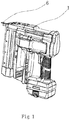
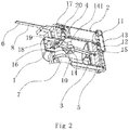
- one embodiment of the nailing machine includes a housing 1, the first cylinder 2, and the second cylinder 3, whose tail ends communicate with each other.
- the first cylinder 2 and the second cylinder 3 are arranged side by side on the housing 1.
- the tail end of the first cylinder 2 is provided with a first hole 11.
- the tail end of the second cylinder 3 is provided with a second hole 12.
- the first hole 11 communicates with the second hole 12 through the third hole 13.
- the first cylinder 2 has a first piston 4 inside.
- the first piston 4 is fixedly connected to the striker 6.
- the second cylinder 3 has a second piston 5 inside.
- the second piston 5 is connected with the motor 7.
- the striker 6 has a locking part 8.
- the nailing machine also includes a pawl 9 capable of snapping at the locking part 8.
- the motor 7 can reciprocate the second piston 5 and also drive the pawl 9 to disengage from the locking part 8.
- the motor 7 in one embodiment is a direct current motor 7.
- the rotating shaft of the direct current motor 7 is fixedly connected with an hinge axle 14 that is capable of rotating circumferentially about the axis of the rotating shaft through a crank 10.
- the hinge axle 14 is parallel to the rotation axis of the motor 7.
- the hinge axle 14 is also pivotally connected with the rod 15 connected with the second piston 5.
- One end of the rod 15 is pivotally connected to the hinge axle 14.
- the other end is hinged on the second piston 5.
- the DC motor 7 reciprocates the second piston 5 between the first position and the second position of the second cylinder 3. When the second piston 5 is in the first position, a negative pressure is formed in the second cylinder 3.
- the first piston 4 is subject to suction. Since the first cylinder 2 and the second cylinder 3 are communicated with each other.
- the first piston 4 moves inward.
- the striker 6 also retracts into the first cylinder 2.
- the pawl 9 snaps at the locking part 8 of the striker 6, limiting the movement of the striker 6.
- the DC motor 7 drives the second piston 5 for the next stroke.
- the second piston 5 moves to the second position. Since the first piston 4 and the striker 6 are constrained by the snap hold between the pawl 9 and the locking part 8, the first piston 4 and the striker 6 remain stationary.
- the movement of the second piston 5 compresses the air, forming a high-pressure gas.
- the motor 7 drives the second piston 5 to compress the air and the compressed air is stored in the passage of the third hole 13.
- motor 7 continues to work, triggers the pawl 9, so that the pawl 9 disengages from the locking part 8.
- the striker 6 ejects rapidly and forcefully along with the first piston 4.
- the nailing machine is also often used in conjunction with a nail magazine capable of holding strip nails.
- the strip nails are placed inside the magazine.
- the first nail of the strip nails can be opposite to the striker 6. Through the impact of the striker 6, the nails are nailed into the object or shot out. Since a motor 7 is used to compress the air and to trigger the pawl 9, the orderly integration achieves a rapid and continuous firing of strip nails.
- the pawl 9 is connected to the housing 1 through a first pivot 16.
- the housing 1 is also provided with a second pivot 17.
- a first link 18 is fixedly connected to the first pivot 16.
- the second pivot 17 is fixedly connected with the swing bar 20.
- a second link 19 is arranged between the swing bar 20 and the first link 18. The two ends of the second link 19 are respectively hinged with the swing bar 20 and the first link 18. t he swing bar 20 can abut against the hinge axle 14.
- the hinge axle 14 is rotated by the DC motor 7, which during each revolution, can trigger the swing bar 20 once.
- the swing bar 20 drives the first link 18 to rotate through the second link 19, and, then drives the first pivot 16 to rotate, so as to drive the pawl 9 connected to the first pivot 16 to move, realizing the trigger.
- the striker 6 is a strip-shaped plate.
- the locking part 8 is a groove 81 formed on the side wall of the striker 6.
- the groove wall of the groove 81 is composed of an abutment 811 and an arc 812.
- the abutment 811 is perpendicular to the length direction of the striker 6, arc 812 extends from the side wall of striker 6 to abutment 811.
- the pawl 9 can abut against the abutment 811, so that the striker 6 cannot move forward in the first cylinder 2.
- the pawl 9 is also connected with a torsion spring 21, capable of abutting the end of the pawl 9 against the side wall of the striker 6, which ensures that the pawl 9 abuts against the locking part 8 to achieve the limiting effect.
Landscapes
- Engineering & Computer Science (AREA)
- Mechanical Engineering (AREA)
- Physics & Mathematics (AREA)
- Fluid Mechanics (AREA)
- Portable Nailing Machines And Staplers (AREA)
Priority Applications (1)
| Application Number | Priority Date | Filing Date | Title |
|---|---|---|---|
| PL16813539T PL3315260T3 (pl) | 2015-06-26 | 2016-03-25 | Gwoździarka |
Applications Claiming Priority (2)
| Application Number | Priority Date | Filing Date | Title |
|---|---|---|---|
| CN201520454838.8U CN204736190U (zh) | 2015-06-26 | 2015-06-26 | 一种打钉机 |
| PCT/CN2016/077291 WO2016206423A1 (fr) | 2015-06-26 | 2016-03-25 | Machine à clouer |
Publications (3)
| Publication Number | Publication Date |
|---|---|
| EP3315260A1 true EP3315260A1 (fr) | 2018-05-02 |
| EP3315260A4 EP3315260A4 (fr) | 2019-02-27 |
| EP3315260B1 EP3315260B1 (fr) | 2021-01-06 |
Family
ID=54417946
Family Applications (1)
| Application Number | Title | Priority Date | Filing Date |
|---|---|---|---|
| EP16813539.0A Active EP3315260B1 (fr) | 2015-06-26 | 2016-03-25 | Machine à clouer |
Country Status (9)
| Country | Link |
|---|---|
| US (1) | US10471579B2 (fr) |
| EP (1) | EP3315260B1 (fr) |
| CN (1) | CN204736190U (fr) |
| AU (1) | AU2016282094B2 (fr) |
| CA (1) | CA2990728C (fr) |
| DK (1) | DK3315260T3 (fr) |
| ES (1) | ES2853023T3 (fr) |
| PL (1) | PL3315260T3 (fr) |
| WO (1) | WO2016206423A1 (fr) |
Cited By (3)
| Publication number | Priority date | Publication date | Assignee | Title |
|---|---|---|---|---|
| EP3599057A1 (fr) * | 2018-07-26 | 2020-01-29 | Techtronic Cordless GP | Outil pneumatique |
| EP3670092A1 (fr) * | 2018-08-25 | 2020-06-24 | Taizhou Dingba Power Tools Co., Ltd. | Cloueuse |
| EP4119298A3 (fr) * | 2021-07-16 | 2023-05-03 | Techtronic Cordless GP | Dispositif d'entraînement de fixation motorisé |
Families Citing this family (14)
| Publication number | Priority date | Publication date | Assignee | Title |
|---|---|---|---|---|
| CN204736190U (zh) | 2015-06-26 | 2015-11-04 | 张华定 | 一种打钉机 |
| CN107717875A (zh) * | 2016-08-10 | 2018-02-23 | 南京德朔实业有限公司 | 动力工具 |
| CN206614481U (zh) * | 2016-12-09 | 2017-11-07 | 南京德朔实业有限公司 | 打钉枪 |
| US10800022B2 (en) * | 2017-02-09 | 2020-10-13 | Illinois Tool Works Inc. | Powered-fastener-driving tool including a driver blade having a varying cross-section |
| CN108656027A (zh) * | 2017-03-28 | 2018-10-16 | 南京德朔实业有限公司 | 钉枪 |
| CN109623737B (zh) * | 2018-12-17 | 2022-06-21 | 浙江普莱得电器股份有限公司 | 一种打钉稳定的钉枪 |
| CN109605285B (zh) | 2019-01-31 | 2024-03-19 | 台州市钉霸电动工具有限公司 | 一种打钉枪 |
| CN111050533A (zh) * | 2019-12-31 | 2020-04-21 | 杭州新星光电有限公司 | 散热装置及包含该散热装置的打钉枪 |
| CN111347376B (zh) * | 2020-04-17 | 2022-12-02 | 南京腾亚精工科技股份有限公司 | 一种防误射击打工具 |
| US11819989B2 (en) | 2020-07-07 | 2023-11-21 | Techtronic Cordless Gp | Powered fastener driver |
| EP4237201A4 (fr) | 2020-10-30 | 2024-12-11 | Milwaukee Electric Tool Corporation | Dispositif d'entraînement d'élément de fixation motorisé |
| CN114851135B (zh) * | 2021-01-20 | 2025-12-23 | 苏州宝时得电动工具有限公司 | 钉枪 |
| CN114750111B (zh) * | 2022-04-22 | 2022-11-25 | 四川轻化工大学 | 一种双气缸电动固钉器 |
| US12395046B2 (en) | 2022-07-22 | 2025-08-19 | Techtronic Cordless Gp | Firmware control providing a soft stop on compression drive nailer |
Family Cites Families (10)
| Publication number | Priority date | Publication date | Assignee | Title |
|---|---|---|---|---|
| DE102005000062A1 (de) * | 2005-05-18 | 2006-11-23 | Hilti Ag | Elektrisch betriebenes Eintreibgerät |
| DE102005000107B4 (de) * | 2005-08-25 | 2014-03-13 | Hilti Aktiengesellschaft | Pneumatisch betriebenes Setzgerät |
| US8875969B2 (en) * | 2007-02-09 | 2014-11-04 | Tricord Solutions, Inc. | Fastener driving apparatus |
| US7793811B1 (en) * | 2009-02-25 | 2010-09-14 | Tricord Solutions, Inc. | Fastener driving apparatus |
| MX344420B (es) * | 2010-11-04 | 2016-12-15 | John Witzigreuter | Aparato de clavado de sujetador. |
| JP5800749B2 (ja) | 2012-04-09 | 2015-10-28 | 株式会社マキタ | 打込み工具 |
| US8733610B2 (en) | 2012-08-21 | 2014-05-27 | Tricord Solutions, Inc. | Fastener driving apparatus |
| CN103846868B (zh) | 2012-12-06 | 2016-08-03 | 苏州宝时得电动工具有限公司 | 打钉枪 |
| CN204019481U (zh) | 2014-07-01 | 2014-12-17 | 台州市大江实业有限公司 | 一种气动打钉装置 |
| CN204736190U (zh) * | 2015-06-26 | 2015-11-04 | 张华定 | 一种打钉机 |
-
2015
- 2015-06-26 CN CN201520454838.8U patent/CN204736190U/zh not_active Expired - Lifetime
-
2016
- 2016-03-25 US US15/738,142 patent/US10471579B2/en active Active
- 2016-03-25 WO PCT/CN2016/077291 patent/WO2016206423A1/fr not_active Ceased
- 2016-03-25 ES ES16813539T patent/ES2853023T3/es active Active
- 2016-03-25 EP EP16813539.0A patent/EP3315260B1/fr active Active
- 2016-03-25 AU AU2016282094A patent/AU2016282094B2/en active Active
- 2016-03-25 PL PL16813539T patent/PL3315260T3/pl unknown
- 2016-03-25 CA CA2990728A patent/CA2990728C/fr active Active
- 2016-03-25 DK DK16813539.0T patent/DK3315260T3/da active
Cited By (6)
| Publication number | Priority date | Publication date | Assignee | Title |
|---|---|---|---|---|
| EP3599057A1 (fr) * | 2018-07-26 | 2020-01-29 | Techtronic Cordless GP | Outil pneumatique |
| US11400573B2 (en) | 2018-07-26 | 2022-08-02 | Techtronic Power Tools Technology Limited | Pneumatic tool |
| EP3670092A1 (fr) * | 2018-08-25 | 2020-06-24 | Taizhou Dingba Power Tools Co., Ltd. | Cloueuse |
| AU2019219851B2 (en) * | 2018-08-25 | 2020-12-24 | Taizhou Dingba Power Tools Co., Ltd. | Nail Gun |
| EP4119298A3 (fr) * | 2021-07-16 | 2023-05-03 | Techtronic Cordless GP | Dispositif d'entraînement de fixation motorisé |
| EP4286101A1 (fr) * | 2021-07-16 | 2023-12-06 | Techtronic Cordless GP | Dispositif d'entraînement d'élément de fixation motorisé |
Also Published As
| Publication number | Publication date |
|---|---|
| PL3315260T3 (pl) | 2021-06-28 |
| US10471579B2 (en) | 2019-11-12 |
| US20180222028A1 (en) | 2018-08-09 |
| CA2990728C (fr) | 2020-03-10 |
| WO2016206423A1 (fr) | 2016-12-29 |
| AU2016282094B2 (en) | 2018-12-20 |
| CN204736190U (zh) | 2015-11-04 |
| EP3315260B1 (fr) | 2021-01-06 |
| EP3315260A4 (fr) | 2019-02-27 |
| CA2990728A1 (fr) | 2016-12-29 |
| AU2016282094A1 (en) | 2018-01-18 |
| ES2853023T3 (es) | 2021-09-14 |
| DK3315260T3 (da) | 2021-02-22 |
Similar Documents
| Publication | Publication Date | Title |
|---|---|---|
| EP3315260A1 (fr) | Machine à clouer | |
| US9844865B2 (en) | Driver tool | |
| US11148268B2 (en) | Nail gun | |
| USRE44344E1 (en) | Nailer device | |
| US7484647B2 (en) | Nail gun with a safety assembly | |
| CN111496728B (zh) | 气动线性紧固件驱动工具 | |
| CN110450108A (zh) | 气动工具 | |
| US20180043518A1 (en) | Power tool | |
| WO2019220929A1 (fr) | Dispositif d'entraînement | |
| US3688848A (en) | Air spring bleed assembly | |
| US20250375865A1 (en) | Fastening tool having position biased released valve | |
| WO2022156698A1 (fr) | Cloueuse | |
| CN115431225B (zh) | 钉枪 | |
| US10406664B2 (en) | Impact structure | |
| US20260102889A1 (en) | Nailing machine | |
| CN222589666U (zh) | 气动射钉枪 | |
| US20250345909A1 (en) | Fastener driver | |
| CN223369349U (zh) | 一种卷钉枪的击发结构 | |
| WO2025241175A1 (fr) | Dispositif de chargement de clous de pistolet à clous | |
| CN202922538U (zh) | 敲钉机 |
Legal Events
| Date | Code | Title | Description |
|---|---|---|---|
| STAA | Information on the status of an ep patent application or granted ep patent |
Free format text: STATUS: THE INTERNATIONAL PUBLICATION HAS BEEN MADE |
|
| PUAI | Public reference made under article 153(3) epc to a published international application that has entered the european phase |
Free format text: ORIGINAL CODE: 0009012 |
|
| STAA | Information on the status of an ep patent application or granted ep patent |
Free format text: STATUS: REQUEST FOR EXAMINATION WAS MADE |
|
| 17P | Request for examination filed |
Effective date: 20171221 |
|
| AK | Designated contracting states |
Kind code of ref document: A1 Designated state(s): AL AT BE BG CH CY CZ DE DK EE ES FI FR GB GR HR HU IE IS IT LI LT LU LV MC MK MT NL NO PL PT RO RS SE SI SK SM TR |
|
| AX | Request for extension of the european patent |
Extension state: BA ME |
|
| DAV | Request for validation of the european patent (deleted) | ||
| DAX | Request for extension of the european patent (deleted) | ||
| A4 | Supplementary search report drawn up and despatched |
Effective date: 20190124 |
|
| RIC1 | Information provided on ipc code assigned before grant |
Ipc: B25C 1/06 20060101AFI20190118BHEP |
|
| RAP1 | Party data changed (applicant data changed or rights of an application transferred) |
Owner name: TAIZHOU DINGBA POWER TOOLS CO., LTD. |
|
| RIN1 | Information on inventor provided before grant (corrected) |
Inventor name: ZHANG, HUADING |
|
| GRAP | Despatch of communication of intention to grant a patent |
Free format text: ORIGINAL CODE: EPIDOSNIGR1 |
|
| STAA | Information on the status of an ep patent application or granted ep patent |
Free format text: STATUS: GRANT OF PATENT IS INTENDED |
|
| GRAS | Grant fee paid |
Free format text: ORIGINAL CODE: EPIDOSNIGR3 |
|
| GRAA | (expected) grant |
Free format text: ORIGINAL CODE: 0009210 |
|
| STAA | Information on the status of an ep patent application or granted ep patent |
Free format text: STATUS: THE PATENT HAS BEEN GRANTED |
|
| INTG | Intention to grant announced |
Effective date: 20201112 |
|
| AK | Designated contracting states |
Kind code of ref document: B1 Designated state(s): AL AT BE BG CH CY CZ DE DK EE ES FI FR GB GR HR HU IE IS IT LI LT LU LV MC MK MT NL NO PL PT RO RS SE SI SK SM TR |
|
| REG | Reference to a national code |
Ref country code: GB Ref legal event code: FG4D |
|
| REG | Reference to a national code |
Ref country code: AT Ref legal event code: REF Ref document number: 1351853 Country of ref document: AT Kind code of ref document: T Effective date: 20210115 Ref country code: CH Ref legal event code: EP |
|
| REG | Reference to a national code |
Ref country code: DE Ref legal event code: R096 Ref document number: 602016051128 Country of ref document: DE |
|
| REG | Reference to a national code |
Ref country code: IE Ref legal event code: FG4D |
|
| REG | Reference to a national code |
Ref country code: CH Ref legal event code: NV Representative=s name: TR-IP CONSULTING LLC, CH |
|
| REG | Reference to a national code |
Ref country code: FI Ref legal event code: FGE |
|
| REG | Reference to a national code |
Ref country code: DK Ref legal event code: T3 Effective date: 20210217 |
|
| REG | Reference to a national code |
Ref country code: SE Ref legal event code: TRGR |
|
| REG | Reference to a national code |
Ref country code: NL Ref legal event code: FP |
|
| REG | Reference to a national code |
Ref country code: NO Ref legal event code: T2 Effective date: 20210106 |
|
| REG | Reference to a national code |
Ref country code: AT Ref legal event code: MK05 Ref document number: 1351853 Country of ref document: AT Kind code of ref document: T Effective date: 20210106 |
|
| REG | Reference to a national code |
Ref country code: LT Ref legal event code: MG9D |
|
| PG25 | Lapsed in a contracting state [announced via postgrant information from national office to epo] |
Ref country code: GR Free format text: LAPSE BECAUSE OF FAILURE TO SUBMIT A TRANSLATION OF THE DESCRIPTION OR TO PAY THE FEE WITHIN THE PRESCRIBED TIME-LIMIT Effective date: 20210407 Ref country code: HR Free format text: LAPSE BECAUSE OF FAILURE TO SUBMIT A TRANSLATION OF THE DESCRIPTION OR TO PAY THE FEE WITHIN THE PRESCRIBED TIME-LIMIT Effective date: 20210106 Ref country code: PT Free format text: LAPSE BECAUSE OF FAILURE TO SUBMIT A TRANSLATION OF THE DESCRIPTION OR TO PAY THE FEE WITHIN THE PRESCRIBED TIME-LIMIT Effective date: 20210506 Ref country code: LT Free format text: LAPSE BECAUSE OF FAILURE TO SUBMIT A TRANSLATION OF THE DESCRIPTION OR TO PAY THE FEE WITHIN THE PRESCRIBED TIME-LIMIT Effective date: 20210106 Ref country code: BG Free format text: LAPSE BECAUSE OF FAILURE TO SUBMIT A TRANSLATION OF THE DESCRIPTION OR TO PAY THE FEE WITHIN THE PRESCRIBED TIME-LIMIT Effective date: 20210406 |
|
| PG25 | Lapsed in a contracting state [announced via postgrant information from national office to epo] |
Ref country code: AT Free format text: LAPSE BECAUSE OF FAILURE TO SUBMIT A TRANSLATION OF THE DESCRIPTION OR TO PAY THE FEE WITHIN THE PRESCRIBED TIME-LIMIT Effective date: 20210106 Ref country code: RS Free format text: LAPSE BECAUSE OF FAILURE TO SUBMIT A TRANSLATION OF THE DESCRIPTION OR TO PAY THE FEE WITHIN THE PRESCRIBED TIME-LIMIT Effective date: 20210106 Ref country code: LV Free format text: LAPSE BECAUSE OF FAILURE TO SUBMIT A TRANSLATION OF THE DESCRIPTION OR TO PAY THE FEE WITHIN THE PRESCRIBED TIME-LIMIT Effective date: 20210106 |
|
| PG25 | Lapsed in a contracting state [announced via postgrant information from national office to epo] |
Ref country code: IS Free format text: LAPSE BECAUSE OF FAILURE TO SUBMIT A TRANSLATION OF THE DESCRIPTION OR TO PAY THE FEE WITHIN THE PRESCRIBED TIME-LIMIT Effective date: 20210506 |
|
| REG | Reference to a national code |
Ref country code: DE Ref legal event code: R097 Ref document number: 602016051128 Country of ref document: DE |
|
| PG25 | Lapsed in a contracting state [announced via postgrant information from national office to epo] |
Ref country code: CZ Free format text: LAPSE BECAUSE OF FAILURE TO SUBMIT A TRANSLATION OF THE DESCRIPTION OR TO PAY THE FEE WITHIN THE PRESCRIBED TIME-LIMIT Effective date: 20210106 Ref country code: EE Free format text: LAPSE BECAUSE OF FAILURE TO SUBMIT A TRANSLATION OF THE DESCRIPTION OR TO PAY THE FEE WITHIN THE PRESCRIBED TIME-LIMIT Effective date: 20210106 Ref country code: MC Free format text: LAPSE BECAUSE OF FAILURE TO SUBMIT A TRANSLATION OF THE DESCRIPTION OR TO PAY THE FEE WITHIN THE PRESCRIBED TIME-LIMIT Effective date: 20210106 Ref country code: SM Free format text: LAPSE BECAUSE OF FAILURE TO SUBMIT A TRANSLATION OF THE DESCRIPTION OR TO PAY THE FEE WITHIN THE PRESCRIBED TIME-LIMIT Effective date: 20210106 |
|
| PLBE | No opposition filed within time limit |
Free format text: ORIGINAL CODE: 0009261 |
|
| STAA | Information on the status of an ep patent application or granted ep patent |
Free format text: STATUS: NO OPPOSITION FILED WITHIN TIME LIMIT |
|
| PG25 | Lapsed in a contracting state [announced via postgrant information from national office to epo] |
Ref country code: SK Free format text: LAPSE BECAUSE OF FAILURE TO SUBMIT A TRANSLATION OF THE DESCRIPTION OR TO PAY THE FEE WITHIN THE PRESCRIBED TIME-LIMIT Effective date: 20210106 Ref country code: RO Free format text: LAPSE BECAUSE OF FAILURE TO SUBMIT A TRANSLATION OF THE DESCRIPTION OR TO PAY THE FEE WITHIN THE PRESCRIBED TIME-LIMIT Effective date: 20210106 |
|
| 26N | No opposition filed |
Effective date: 20211007 |
|
| PG25 | Lapsed in a contracting state [announced via postgrant information from national office to epo] |
Ref country code: IE Free format text: LAPSE BECAUSE OF NON-PAYMENT OF DUE FEES Effective date: 20210325 Ref country code: LU Free format text: LAPSE BECAUSE OF NON-PAYMENT OF DUE FEES Effective date: 20210325 Ref country code: AL Free format text: LAPSE BECAUSE OF FAILURE TO SUBMIT A TRANSLATION OF THE DESCRIPTION OR TO PAY THE FEE WITHIN THE PRESCRIBED TIME-LIMIT Effective date: 20210106 |
|
| PG25 | Lapsed in a contracting state [announced via postgrant information from national office to epo] |
Ref country code: SI Free format text: LAPSE BECAUSE OF FAILURE TO SUBMIT A TRANSLATION OF THE DESCRIPTION OR TO PAY THE FEE WITHIN THE PRESCRIBED TIME-LIMIT Effective date: 20210106 |
|
| PG25 | Lapsed in a contracting state [announced via postgrant information from national office to epo] |
Ref country code: IT Free format text: LAPSE BECAUSE OF FAILURE TO SUBMIT A TRANSLATION OF THE DESCRIPTION OR TO PAY THE FEE WITHIN THE PRESCRIBED TIME-LIMIT Effective date: 20210106 |
|
| PG25 | Lapsed in a contracting state [announced via postgrant information from national office to epo] |
Ref country code: IS Free format text: LAPSE BECAUSE OF FAILURE TO SUBMIT A TRANSLATION OF THE DESCRIPTION OR TO PAY THE FEE WITHIN THE PRESCRIBED TIME-LIMIT Effective date: 20210506 |
|
| PG25 | Lapsed in a contracting state [announced via postgrant information from national office to epo] |
Ref country code: CY Free format text: LAPSE BECAUSE OF FAILURE TO SUBMIT A TRANSLATION OF THE DESCRIPTION OR TO PAY THE FEE WITHIN THE PRESCRIBED TIME-LIMIT Effective date: 20210106 |
|
| PG25 | Lapsed in a contracting state [announced via postgrant information from national office to epo] |
Ref country code: HU Free format text: LAPSE BECAUSE OF FAILURE TO SUBMIT A TRANSLATION OF THE DESCRIPTION OR TO PAY THE FEE WITHIN THE PRESCRIBED TIME-LIMIT; INVALID AB INITIO Effective date: 20160325 |
|
| PG25 | Lapsed in a contracting state [announced via postgrant information from national office to epo] |
Ref country code: MK Free format text: LAPSE BECAUSE OF FAILURE TO SUBMIT A TRANSLATION OF THE DESCRIPTION OR TO PAY THE FEE WITHIN THE PRESCRIBED TIME-LIMIT Effective date: 20210106 |
|
| PG25 | Lapsed in a contracting state [announced via postgrant information from national office to epo] |
Ref country code: MT Free format text: LAPSE BECAUSE OF FAILURE TO SUBMIT A TRANSLATION OF THE DESCRIPTION OR TO PAY THE FEE WITHIN THE PRESCRIBED TIME-LIMIT Effective date: 20210106 |
|
| PGFP | Annual fee paid to national office [announced via postgrant information from national office to epo] |
Ref country code: ES Payment date: 20250410 Year of fee payment: 10 |
|
| PGFP | Annual fee paid to national office [announced via postgrant information from national office to epo] |
Ref country code: CH Payment date: 20250401 Year of fee payment: 10 |
|
| PG25 | Lapsed in a contracting state [announced via postgrant information from national office to epo] |
Ref country code: TR Free format text: LAPSE BECAUSE OF FAILURE TO SUBMIT A TRANSLATION OF THE DESCRIPTION OR TO PAY THE FEE WITHIN THE PRESCRIBED TIME-LIMIT Effective date: 20210106 |
|
| PGFP | Annual fee paid to national office [announced via postgrant information from national office to epo] |
Ref country code: NL Payment date: 20260226 Year of fee payment: 11 |
|
| REG | Reference to a national code |
Ref country code: CH Ref legal event code: U11 Free format text: ST27 STATUS EVENT CODE: U-0-0-U10-U11 (AS PROVIDED BY THE NATIONAL OFFICE) Effective date: 20260401 |
|
| PGFP | Annual fee paid to national office [announced via postgrant information from national office to epo] |
Ref country code: SE Payment date: 20260320 Year of fee payment: 11 |
|
| PGFP | Annual fee paid to national office [announced via postgrant information from national office to epo] |
Ref country code: GB Payment date: 20260323 Year of fee payment: 11 |
|
| PGFP | Annual fee paid to national office [announced via postgrant information from national office to epo] |
Ref country code: DE Payment date: 20260313 Year of fee payment: 11 Ref country code: NO Payment date: 20260226 Year of fee payment: 11 Ref country code: DK Payment date: 20260226 Year of fee payment: 11 |
|
| PGFP | Annual fee paid to national office [announced via postgrant information from national office to epo] |
Ref country code: FI Payment date: 20260224 Year of fee payment: 11 Ref country code: BE Payment date: 20260324 Year of fee payment: 11 |
|
| PGFP | Annual fee paid to national office [announced via postgrant information from national office to epo] |
Ref country code: FR Payment date: 20260330 Year of fee payment: 11 |
|
| PGFP | Annual fee paid to national office [announced via postgrant information from national office to epo] |
Ref country code: PL Payment date: 20260302 Year of fee payment: 11 |