EP3315410B1 - Einstellbarer sensor oder sensornetzwerk zur selektiven verbesserung der identifikation von ausgewählten chemischen spezies - Google Patents
Einstellbarer sensor oder sensornetzwerk zur selektiven verbesserung der identifikation von ausgewählten chemischen spezies Download PDFInfo
- Publication number
- EP3315410B1 EP3315410B1 EP17198105.3A EP17198105A EP3315410B1 EP 3315410 B1 EP3315410 B1 EP 3315410B1 EP 17198105 A EP17198105 A EP 17198105A EP 3315410 B1 EP3315410 B1 EP 3315410B1
- Authority
- EP
- European Patent Office
- Prior art keywords
- sensor
- air
- voltage
- controller
- contaminant
- Prior art date
- Legal status (The legal status is an assumption and is not a legal conclusion. Google has not performed a legal analysis and makes no representation as to the accuracy of the status listed.)
- Active
Links
- 239000013626 chemical specie Substances 0.000 title 1
- 239000000356 contaminant Substances 0.000 claims description 127
- 230000007613 environmental effect Effects 0.000 claims description 8
- 238000004891 communication Methods 0.000 claims description 5
- 238000010408 sweeping Methods 0.000 claims description 5
- 238000011144 upstream manufacturing Methods 0.000 claims description 2
- 239000012855 volatile organic compound Substances 0.000 description 33
- 230000004044 response Effects 0.000 description 28
- CURLTUGMZLYLDI-UHFFFAOYSA-N Carbon dioxide Chemical compound O=C=O CURLTUGMZLYLDI-UHFFFAOYSA-N 0.000 description 26
- 238000000034 method Methods 0.000 description 21
- 230000009471 action Effects 0.000 description 16
- 239000002245 particle Substances 0.000 description 16
- 230000008859 change Effects 0.000 description 14
- 229910002092 carbon dioxide Inorganic materials 0.000 description 13
- 238000010586 diagram Methods 0.000 description 13
- 239000000203 mixture Substances 0.000 description 13
- 239000001569 carbon dioxide Substances 0.000 description 12
- 238000011109 contamination Methods 0.000 description 12
- CBENFWSGALASAD-UHFFFAOYSA-N Ozone Chemical compound [O-][O+]=O CBENFWSGALASAD-UHFFFAOYSA-N 0.000 description 11
- 230000005284 excitation Effects 0.000 description 11
- 230000008569 process Effects 0.000 description 9
- 238000003860 storage Methods 0.000 description 9
- 238000004378 air conditioning Methods 0.000 description 8
- 150000001299 aldehydes Chemical class 0.000 description 8
- 238000004590 computer program Methods 0.000 description 8
- 238000013461 design Methods 0.000 description 8
- 230000006870 function Effects 0.000 description 8
- 239000000463 material Substances 0.000 description 7
- HGINCPLSRVDWNT-UHFFFAOYSA-N Acrolein Chemical compound C=CC=O HGINCPLSRVDWNT-UHFFFAOYSA-N 0.000 description 6
- 150000001875 compounds Chemical class 0.000 description 6
- 238000012545 processing Methods 0.000 description 6
- 238000004887 air purification Methods 0.000 description 5
- 239000012636 effector Substances 0.000 description 5
- 229930195733 hydrocarbon Natural products 0.000 description 5
- 150000002430 hydrocarbons Chemical class 0.000 description 5
- 229910044991 metal oxide Inorganic materials 0.000 description 5
- 150000004706 metal oxides Chemical class 0.000 description 5
- 239000000126 substance Substances 0.000 description 5
- VQTUBCCKSQIDNK-UHFFFAOYSA-N Isobutene Chemical group CC(C)=C VQTUBCCKSQIDNK-UHFFFAOYSA-N 0.000 description 4
- 230000003247 decreasing effect Effects 0.000 description 4
- WSFSSNUMVMOOMR-NJFSPNSNSA-N methanone Chemical compound O=[14CH2] WSFSSNUMVMOOMR-NJFSPNSNSA-N 0.000 description 4
- 239000011882 ultra-fine particle Substances 0.000 description 4
- UGFAIRIUMAVXCW-UHFFFAOYSA-N Carbon monoxide Chemical compound [O+]#[C-] UGFAIRIUMAVXCW-UHFFFAOYSA-N 0.000 description 3
- LFQSCWFLJHTTHZ-UHFFFAOYSA-N Ethanol Chemical compound CCO LFQSCWFLJHTTHZ-UHFFFAOYSA-N 0.000 description 3
- IKHGUXGNUITLKF-XPULMUKRSA-N acetaldehyde Chemical compound [14CH]([14CH3])=O IKHGUXGNUITLKF-XPULMUKRSA-N 0.000 description 3
- 229910002091 carbon monoxide Inorganic materials 0.000 description 3
- 230000000694 effects Effects 0.000 description 3
- 238000004519 manufacturing process Methods 0.000 description 3
- 238000012544 monitoring process Methods 0.000 description 3
- 230000003287 optical effect Effects 0.000 description 3
- 230000003134 recirculating effect Effects 0.000 description 3
- 230000001105 regulatory effect Effects 0.000 description 3
- 238000005070 sampling Methods 0.000 description 3
- 238000009423 ventilation Methods 0.000 description 3
- 239000000443 aerosol Substances 0.000 description 2
- 230000003466 anti-cipated effect Effects 0.000 description 2
- 238000006243 chemical reaction Methods 0.000 description 2
- 230000001276 controlling effect Effects 0.000 description 2
- 238000001816 cooling Methods 0.000 description 2
- 238000002484 cyclic voltammetry Methods 0.000 description 2
- 238000001914 filtration Methods 0.000 description 2
- 150000002484 inorganic compounds Chemical class 0.000 description 2
- 229910010272 inorganic material Inorganic materials 0.000 description 2
- 238000012423 maintenance Methods 0.000 description 2
- 229920000620 organic polymer Polymers 0.000 description 2
- 230000003647 oxidation Effects 0.000 description 2
- 238000007254 oxidation reaction Methods 0.000 description 2
- 230000000644 propagated effect Effects 0.000 description 2
- 239000004065 semiconductor Substances 0.000 description 2
- 239000007787 solid Substances 0.000 description 2
- 238000012546 transfer Methods 0.000 description 2
- 238000010626 work up procedure Methods 0.000 description 2
- OKTJSMMVPCPJKN-UHFFFAOYSA-N Carbon Chemical compound [C] OKTJSMMVPCPJKN-UHFFFAOYSA-N 0.000 description 1
- 239000004215 Carbon black (E152) Substances 0.000 description 1
- -1 SVOC Chemical compound 0.000 description 1
- 238000010521 absorption reaction Methods 0.000 description 1
- 239000003463 adsorbent Substances 0.000 description 1
- 230000002411 adverse Effects 0.000 description 1
- 230000032683 aging Effects 0.000 description 1
- 235000013334 alcoholic beverage Nutrition 0.000 description 1
- 238000003491 array Methods 0.000 description 1
- 239000011324 bead Substances 0.000 description 1
- 230000008901 benefit Effects 0.000 description 1
- 229910052799 carbon Inorganic materials 0.000 description 1
- 238000007084 catalytic combustion reaction Methods 0.000 description 1
- 230000003197 catalytic effect Effects 0.000 description 1
- 239000000919 ceramic Substances 0.000 description 1
- 230000001010 compromised effect Effects 0.000 description 1
- 238000013480 data collection Methods 0.000 description 1
- 238000000354 decomposition reaction Methods 0.000 description 1
- 230000007123 defense Effects 0.000 description 1
- 230000003111 delayed effect Effects 0.000 description 1
- 238000009826 distribution Methods 0.000 description 1
- 238000001537 electron coincidence spectroscopy Methods 0.000 description 1
- 238000005265 energy consumption Methods 0.000 description 1
- 239000003344 environmental pollutant Substances 0.000 description 1
- 238000011156 evaluation Methods 0.000 description 1
- 235000013305 food Nutrition 0.000 description 1
- 238000009472 formulation Methods 0.000 description 1
- 238000002955 isolation Methods 0.000 description 1
- 230000000670 limiting effect Effects 0.000 description 1
- 235000012054 meals Nutrition 0.000 description 1
- 238000005259 measurement Methods 0.000 description 1
- 229910052751 metal Inorganic materials 0.000 description 1
- 239000002184 metal Substances 0.000 description 1
- 238000012986 modification Methods 0.000 description 1
- 230000004048 modification Effects 0.000 description 1
- 210000001331 nose Anatomy 0.000 description 1
- 235000019645 odor Nutrition 0.000 description 1
- 239000013307 optical fiber Substances 0.000 description 1
- 239000013618 particulate matter Substances 0.000 description 1
- 230000000737 periodic effect Effects 0.000 description 1
- BASFCYQUMIYNBI-UHFFFAOYSA-N platinum Chemical compound [Pt] BASFCYQUMIYNBI-UHFFFAOYSA-N 0.000 description 1
- 231100000719 pollutant Toxicity 0.000 description 1
- 229920005597 polymer membrane Polymers 0.000 description 1
- 238000011084 recovery Methods 0.000 description 1
- 230000002829 reductive effect Effects 0.000 description 1
- 238000011160 research Methods 0.000 description 1
- 238000002849 thermal shift Methods 0.000 description 1
- 230000001052 transient effect Effects 0.000 description 1
Images




Classifications
-
- B—PERFORMING OPERATIONS; TRANSPORTING
- B64—AIRCRAFT; AVIATION; COSMONAUTICS
- B64D—EQUIPMENT FOR FITTING IN OR TO AIRCRAFT; FLIGHT SUITS; PARACHUTES; ARRANGEMENT OR MOUNTING OF POWER PLANTS OR PROPULSION TRANSMISSIONS IN AIRCRAFT
- B64D13/00—Arrangements or adaptations of air-treatment apparatus for aircraft crew or passengers, or freight space
-
- B—PERFORMING OPERATIONS; TRANSPORTING
- B64—AIRCRAFT; AVIATION; COSMONAUTICS
- B64D—EQUIPMENT FOR FITTING IN OR TO AIRCRAFT; FLIGHT SUITS; PARACHUTES; ARRANGEMENT OR MOUNTING OF POWER PLANTS OR PROPULSION TRANSMISSIONS IN AIRCRAFT
- B64D13/00—Arrangements or adaptations of air-treatment apparatus for aircraft crew or passengers, or freight space
- B64D13/06—Arrangements or adaptations of air-treatment apparatus for aircraft crew or passengers, or freight space the air being conditioned
-
- G—PHYSICS
- G01—MEASURING; TESTING
- G01N—INVESTIGATING OR ANALYSING MATERIALS BY DETERMINING THEIR CHEMICAL OR PHYSICAL PROPERTIES
- G01N27/00—Investigating or analysing materials by the use of electric, electrochemical, or magnetic means
- G01N27/02—Investigating or analysing materials by the use of electric, electrochemical, or magnetic means by investigating impedance
- G01N27/04—Investigating or analysing materials by the use of electric, electrochemical, or magnetic means by investigating impedance by investigating resistance
- G01N27/12—Investigating or analysing materials by the use of electric, electrochemical, or magnetic means by investigating impedance by investigating resistance of a solid body in dependence upon absorption of a fluid; of a solid body in dependence upon reaction with a fluid, for detecting components in the fluid
-
- G—PHYSICS
- G01—MEASURING; TESTING
- G01N—INVESTIGATING OR ANALYSING MATERIALS BY DETERMINING THEIR CHEMICAL OR PHYSICAL PROPERTIES
- G01N33/00—Investigating or analysing materials by specific methods not covered by groups G01N1/00 - G01N31/00
- G01N33/0004—Gaseous mixtures, e.g. polluted air
- G01N33/0009—General constructional details of gas analysers, e.g. portable test equipment
- G01N33/0027—General constructional details of gas analysers, e.g. portable test equipment concerning the detector
-
- G—PHYSICS
- G01—MEASURING; TESTING
- G01N—INVESTIGATING OR ANALYSING MATERIALS BY DETERMINING THEIR CHEMICAL OR PHYSICAL PROPERTIES
- G01N33/00—Investigating or analysing materials by specific methods not covered by groups G01N1/00 - G01N31/00
- G01N33/0004—Gaseous mixtures, e.g. polluted air
- G01N33/0009—General constructional details of gas analysers, e.g. portable test equipment
- G01N33/0027—General constructional details of gas analysers, e.g. portable test equipment concerning the detector
- G01N33/0036—General constructional details of gas analysers, e.g. portable test equipment concerning the detector specially adapted to detect a particular component
- G01N33/0047—Organic compounds
-
- B—PERFORMING OPERATIONS; TRANSPORTING
- B64—AIRCRAFT; AVIATION; COSMONAUTICS
- B64D—EQUIPMENT FOR FITTING IN OR TO AIRCRAFT; FLIGHT SUITS; PARACHUTES; ARRANGEMENT OR MOUNTING OF POWER PLANTS OR PROPULSION TRANSMISSIONS IN AIRCRAFT
- B64D13/00—Arrangements or adaptations of air-treatment apparatus for aircraft crew or passengers, or freight space
- B64D13/06—Arrangements or adaptations of air-treatment apparatus for aircraft crew or passengers, or freight space the air being conditioned
- B64D2013/0603—Environmental Control Systems
-
- B—PERFORMING OPERATIONS; TRANSPORTING
- B64—AIRCRAFT; AVIATION; COSMONAUTICS
- B64D—EQUIPMENT FOR FITTING IN OR TO AIRCRAFT; FLIGHT SUITS; PARACHUTES; ARRANGEMENT OR MOUNTING OF POWER PLANTS OR PROPULSION TRANSMISSIONS IN AIRCRAFT
- B64D13/00—Arrangements or adaptations of air-treatment apparatus for aircraft crew or passengers, or freight space
- B64D13/06—Arrangements or adaptations of air-treatment apparatus for aircraft crew or passengers, or freight space the air being conditioned
- B64D2013/0603—Environmental Control Systems
- B64D2013/0618—Environmental Control Systems with arrangements for reducing or managing bleed air, using another air source, e.g. ram air
-
- B—PERFORMING OPERATIONS; TRANSPORTING
- B64—AIRCRAFT; AVIATION; COSMONAUTICS
- B64D—EQUIPMENT FOR FITTING IN OR TO AIRCRAFT; FLIGHT SUITS; PARACHUTES; ARRANGEMENT OR MOUNTING OF POWER PLANTS OR PROPULSION TRANSMISSIONS IN AIRCRAFT
- B64D13/00—Arrangements or adaptations of air-treatment apparatus for aircraft crew or passengers, or freight space
- B64D13/06—Arrangements or adaptations of air-treatment apparatus for aircraft crew or passengers, or freight space the air being conditioned
- B64D2013/0603—Environmental Control Systems
- B64D2013/0688—Environmental Control Systems with means for recirculating cabin air
-
- G—PHYSICS
- G01—MEASURING; TESTING
- G01N—INVESTIGATING OR ANALYSING MATERIALS BY DETERMINING THEIR CHEMICAL OR PHYSICAL PROPERTIES
- G01N27/00—Investigating or analysing materials by the use of electric, electrochemical, or magnetic means
- G01N27/02—Investigating or analysing materials by the use of electric, electrochemical, or magnetic means by investigating impedance
- G01N27/04—Investigating or analysing materials by the use of electric, electrochemical, or magnetic means by investigating impedance by investigating resistance
- G01N27/12—Investigating or analysing materials by the use of electric, electrochemical, or magnetic means by investigating impedance by investigating resistance of a solid body in dependence upon absorption of a fluid; of a solid body in dependence upon reaction with a fluid, for detecting components in the fluid
- G01N27/122—Circuits particularly adapted therefor, e.g. linearising circuits
-
- Y—GENERAL TAGGING OF NEW TECHNOLOGICAL DEVELOPMENTS; GENERAL TAGGING OF CROSS-SECTIONAL TECHNOLOGIES SPANNING OVER SEVERAL SECTIONS OF THE IPC; TECHNICAL SUBJECTS COVERED BY FORMER USPC CROSS-REFERENCE ART COLLECTIONS [XRACs] AND DIGESTS
- Y02—TECHNOLOGIES OR APPLICATIONS FOR MITIGATION OR ADAPTATION AGAINST CLIMATE CHANGE
- Y02T—CLIMATE CHANGE MITIGATION TECHNOLOGIES RELATED TO TRANSPORTATION
- Y02T50/00—Aeronautics or air transport
- Y02T50/50—On board measures aiming to increase energy efficiency
Definitions
- the present invention generally relates to apparatus and methods for treatment of airstreams in an Environmental Control System (ECS) to remove contaminants.
- ECS Environmental Control System
- ECSs of various types and complexity are used in military and civil airplanes, helicopter, Mass Transit, Low Speed and High Speed Rail, and spacecraft applications. If fact, environmental control systems in buildings that manage energy consumption operate their systems by controlling contaminant levels or bringing in outside air to dilute contaminants, and require sensors for this process. In aircraft for example, airflow may be circulated to occupied compartments, cargo compartments, and electronic equipment bays. Air containing many pollutants such as particulate matter, aerosols, and hydrocarbons may range in humidity from dry ( ⁇ 2%) to very humid and may be delivered in a heated condition to the cabin from the ECS.
- EP3050801 discloses an ECS having sensors, an air purification subsystem, and a controller in communication with the sensors and air purification subsystem.
- the sensors detect contaminants in outside air supplied through engine and APU bleeds or other air sources including ground supplies and electric compressors, contaminants in recirculated air, particulates in outside air, carbon dioxide in recirculated air, temperature in an environment, and pressure in an environment. These sensed parameters are compared against thresholds. Based on the comparisons, changes to outside air and/or recirculated air are made.
- EP1923697 discloses a gas sensor element for detecting an aldehyde gas in concentrations of several tens of ppb, a process for manufacturing such a material, and a gas sensor element and the like comprising such a material.
- the gas sensor material comprises an organic-inorganic hybrid material in which a conductive organic polymer is intercalated between layers of an inorganic compound having a layer structure and from which a conductive organic polymer not intercalated between the layers of the inorganic compound is removed, and provides a process for manufacturing such a gas sensor material, as well as a chemical sensor member thus providing a chemical sensor material by which the gas sensor material can detect by itself an aldehyde gas in concentrations of several tens of ppb without using a sensitivity-enhancing element such as a gas-concentrating element.
- US5627305 discloses a gas sensing apparatus including a gas sensing device that is self-heated due to an applied voltage, whose resistance variation amount is varied to thereby sense gas; a voltage supply for variably supplying a voltage to the gas sensing device; a current detector for detecting the current flowing through the gas sensing device thereby generating a current-voltage characteristic for the gas sensing apparatus under the effect of a given gas exposure; and a control and judgement portion for controlling the voltage supply to control a variation value of a voltage supplied to the gas sensing device and to determine the kind and density of a gas in an ambient atmosphere, using current-voltage characteristic reference data.
- Exposure duration for occupants can be 14+ hours.
- Air Crews can routinely be assigned to work up to a 16 hour duty day. The duty day can be extended up to the 16 hour limit if there is a maintenance delay or weather. Some international crews are assigned to work a longer duty day. Pilots are limited to flying no more than 100 hours per month, while cabin crew may work up to around 120 hours per month. There are flight safety and security implications for not adequately protecting pilots (who must perform cognitively-demanding safety-sensitive flight duties) and cabin crew (who must maintain cabin safety and security).
- Metal oxide and other kinds of sensors are generic in response when operated with a constant supply voltage and current at a constant environmental response. It is not possible to determine in a steady state operation mode what VOC contaminant might be present. At times it would be useful in a controlled environment when there are only a few major sources of VOC to be able to identify which VOC is being detected.
- metal oxide sensor voltage may change the sensor response to a specific chemical.
- Ethanol may be present in higher concentrations in closed environments, but is not a significant concern from a control perspective, because it is present in significant quantities in alcoholic beverages.
- Formaldehyde, acetaldehyde, acrolein, and other aldehydes are very irritating in low concentrations.
- the air may have more organic contaminants at ground level through top of climb. It is more likely during these flight stages to sense aldehydes than during cruise phase.
- aspects of the present invention may be embodied as a system, method, or computer program product. Accordingly, aspects of the present invention may take the form of an entirely hardware embodiment, an entirely software embodiment (including firmware, resident software, micro-code, etc.) or an embodiment combining software and hardware aspects that may all generally be referred to herein as a "circuit,” “module” or “system.” Furthermore, aspects of the present invention may take the form of a computer program product embodied in one or more computer readable media having computer readable program code embodied thereon.
- a computer readable storage medium is an electronic, magnetic, optical, or semiconductor system, apparatus, or device, or any suitable combination of the foregoing. More specific examples (a non-exhaustive list) of the computer readable storage medium would include the following: a portable computer diskette, a hard disk, a random access memory (RAM), a read-only memory (ROM), an erasable programmable read-only memory (EPROM or Flash memory), a portable compact disc read-only memory (CD-ROM), an optical storage device, a magnetic storage device, or any suitable combination of the foregoing.
- a computer readable storage medium is any tangible medium that can store a program for use by or in connection with an instruction execution system, apparatus, or device.
- a computer readable signal medium may include a propagated data signal with computer readable program code embodied therein, for example, in baseband or as part of a carrier wave. Such a propagated signal may take any of a variety of forms, including, but not limited to, electro-magnetic, optical, or any suitable combination thereof.
- a computer readable signal medium may be any computer readable medium that is not a computer readable storage medium and that can communicate, propagate, or transport a program for use by or in connection with an instruction execution system, apparatus, or device.
- Program code embodied on a computer readable medium may be transmitted using any appropriate medium, including but not limited to wireless, wireline, optical fiber cable, RF, etc., or any suitable combination of the foregoing.
- Computer program code for carrying out operations for aspects of the present invention may be written in any combination of one or more programming languages, including an object oriented programming language such as Java, Smalltalk, C++ or the like and conventional procedural programming languages, such as the "C" programming language or similar programming languages.
- the program code may execute entirely on the user's computer, partly on the user's computer, as a stand-alone software package, partly on the user's computer and partly on a remote computer or entirely on the remote computer or server.
- the remote computer may be connected to the user's computer through any type of network, including a local area network (LAN) or a wide area network (WAN), or the connection may be made to an external computer (for example, through the Internet using an Internet Service Provider).
- LAN local area network
- WAN wide area network
- Internet Service Provider for example, AT&T, MCI, Sprint, EarthLink, MSN, GTE, etc.
- These computer program instructions may also be stored in a computer readable storage medium that can direct a computer, other programmable data processing apparatus, or other devices to function in a particular manner, such that the instructions stored in the computer readable storage medium produce an article of manufacture including instructions which implement the function/act specified in the flowchart and/or block diagram block or blocks.
- the computer program instructions may also be loaded onto a computer, other programmable data processing apparatus, or other devices to cause a series of operational steps to be performed on the computer, other programmable apparatus or other devices to produce a computer implemented process such that the instructions which execute on the computer or other programmable apparatus provide processes for implementing the functions/acts specified in the flowchart and/or block diagram block or blocks.
- the present invention provides an environmental control system (ECS) that can continuously detect changing contaminants - both in kind and degree - in contaminated air in the ECS.
- the contaminated air may include outside air entering the ECS through engines or APU, or other air sources including ground supplies and electric compressors, as well as recirculating air in the ECS.
- a controller of the ECS may receive contamination signals from one or more sensors that sense one or more contaminants in the contaminated air.
- TPO Temperature Programmed Oxidation
- the sweeping of voltage could be in any number of forms.
- the current could rise and fall in a sinusoidal pattern. Alternatively, it could rise and fall in a saw tooth pattern.
- a controlled change to an input voltage to the sensor can be provided while continuously monitoring sensor response. Continuously ramping the voltage up or down at a fixed rate, while monitoring changes in sensor resistance output, can indicate the type of contaminant present - whether there is only a single contaminant or multiple contaminants.
- the sensor signals can be supplied to a processor that evaluates the signals against a sensor signal baseline. The processor, knowing the phase of environment operation from an input, such as a pressure transducer, can determine whether corrective action to a signal should or should not be implemented.
- each sensor can be tuned with a sensor input voltage that is specific to a contaminant class.
- the array of sensors may simultaneously return signals to a processor more rapidly than a single sensor.
- a sensor array may enable an ECS to identify and respond to a VOC contaminant in a more rapid fashion.
- One of the sensors in the array could be tuned to monitor ozone.
- a benefit of a sensor array is that it provides an element of sensor redundancy in the event of a failure of one of the sensors.
- FIG. 1 is a block diagram of an ECS 10 according to an exemplary embodiment of the present invention.
- the ECS 10 may include a controller 11, such as a computer having a processor and a memory, in continuous or intermittent communication with an air purification subsystem 13 and one or more sensors 12.
- the sensors 12 may be positioned in various points throughout the ECS to sense contaminants in, and/or air characteristics of, the outside air supplied through engine or APU bleeds or other air sources including ground supplies and electric compressors, and/or recirculating air in the ECS and/or, in particular, an environment 14, such an aircraft cabin.
- the contaminants in the ECS may include, for example, VOCs, SVOCs, formaldehyde, acetaldehyde, acrolein and other aldehydes, ultrafine particles (UFPs), carbon monoxide, carbon dioxide, and ozone.
- VOCs VOCs
- SVOCs formaldehyde
- acetaldehyde acetaldehyde
- acrolein aldehydes
- UFPs ultrafine particles
- carbon monoxide carbon dioxide
- ozone ozone
- One or more of the sensors 12 can be any sensor capable of sensing the anticipated contaminants in the contaminated air.
- One or more of the sensors can sense the identity and amount of the individual contaminants in the contaminant air.
- at least three classes of solid state gas sensors could be employed, individually or in combination, by this invention.
- CV cyclic voltammetry
- CCS catalytic combustion sensors
- hot wire sensors sometimes known as “pellistor” or catalytic bead sensors, platinum wire sensors, or other metal or doped polymer membrane sensors.
- a third class of sensors include conductometric or chemiresistance based gas sensors.
- Conductometric sensors includes the range of formulations of metal oxides synthesized in the form of porous ceramics that may be used to create metal oxide sensors.
- One or more of the sensors 12 can be any sensor capable of sensing anticipated air characteristics, such as temperature and pressure or gas composition, of the contaminated air.
- anticipated air characteristics such as temperature and pressure or gas composition
- part numbers 51090026-51 and 1090030-51 by Honeywell for temperature and pressure sensors could be used.
- the controller 11 can include a processor and a memory that can store instructions to be executed by the processor to implement a method of removing contaminants from, and/or change air characteristics in, a space to be occupied by humans, such as the cabin of an aircraft, according to the present invention.
- the controller 11 may receive contamination signals from sensor(s) 12 which may sense contaminants from, for example, a cabin filter, a filter to a mix manifold, an ECS pack to the mix manifold, and/or the mix manifold to the cabin.
- the controller 11 may also receive contamination signals from sensor(s) 12 which may sense contaminants in bleed air coming from, for example, one or more engines and/or an auxiliary power unit (APU).
- the controller 11 may receive characteristic signals from sensor(s) 12 which may sense air characteristics from, for example, the cabin. The characteristics may include temperature and pressure.
- the controller 11 may then compare the contamination signals and/or characteristic signals to one or more thresholds that may relate to, for example, cabin pressure, cabin temperature, particulate mass and VOC concentrations.
- the controller 11 may compare contamination signals to a contaminant concentration look up table that may have information/data of contaminant class and/or contaminant concentration versus sensor response (e.g., resistance/current) and applied voltage.
- the controller may compare air characteristic signals to a look up table that may have information/data of temperature requirements in a cabin as promulgated by a government agency. A similar comparison may occur for the air characteristic of pressure in a cabin.
- the controller 11 may then command a valve to alter valve opening/closing and thereby alter a flow of outside air. Also, in addition to or in lieu of the foregoing command, the controller may command a fan to alter a fan speed of recirculated air. Alternatively, the response of the controller may be to modulate an air purification device, increasing or decreasing its power to effect the desired change in air contaminant concentrations.
- the controller may command an outflow valve to open or close.
- the valve may enable combined outside and recirculated air to enter the cabin as cabin air.
- FIG. 1B is an exemplary embodiment of the ECS 10 depicted in FIG.1A .
- the controller 11 may control one or more of the components and/or subsystems of the ECS 10.
- the ECS 10 may include a pneumatic bleed air precooler 16 that cools outside or bleed air 22 supplied through engine or APU bleeds and/or other air sources including ground supplies and electric compressors, entering the ECS 10.
- the outside air 22 supplied through engine or APU bleeds or other air sources including ground supplies and electric compressors may have contaminants that, at certain levels, may be undesirable for occupants in the environment 14.
- the pneumatic bleed air precooler 17 may be of any design well known in the art, such as a pneumatic bleed air precooler made by Honeywell International Inc.
- the pneumatic bleed air precooler 16 may cause a cooling in air temperature whereby, upon cooling, the temperature of the air exiting the pneumatic bleed air precooler 16 can be, in embodiments, in a range of from about 135°C to about 260°C, or from about 135°C to about 200°C, or from about 135°C to about 150°C.
- a hydrocarbon and ozone converter 17 may receive air from the precooler 16 and convert hydrocarbons and ozone in the air to compounds that are believed to be non-harmful to humans.
- the converter 17 may be of any design well known in the art, such as an ozone converter made by Honeywell, part number 2341590-1, or a volatile organic compound and ozone converter made by Honeywell, part number 67200008-00.
- the converter 17 may convert a percentage of the total hydrocarbons wherein, in embodiments, the amount of hydrocarbons in the air exiting the converter 17 may be in a range of from about 0 ug/M3 to about 4000 ug/M3, or from about 0 ppmV to about 0.5 ppmV isobutylene equivalents, or from about 0 ug/M3 to about 500 ug/M3 isobutylene equivalents, or from about 0 ppmV isobutylene equivalents to about 0.1 ppmV isobutylene equivalents.
- the converter 17 may convert a percentage of the total ozone wherein the amount of ozone in the air exiting the converter 17 may be, in embodiments, in a range of from about 0 ppmV to about 0.1 ppmV, or from about 0 ppmV to about 0.25 ppmV.
- a particulate filter 19a may receive air from the converter 17 to filter out particulates of a desired size.
- the particulates exiting the filter 19a can be, in embodiments, of a size of from about 0 um to about 0.3 um for 99% HEPA filtration at 0.3 um.
- the filter 19a may be of any design well known in the art, such as a filter made by Honeywell SP Defense under the trade name FMM7TM.
- the filter may contain additional beds of adsorbent to remove aldehydes and ultrafine particles with a size range of 10 to 200 nm that are products of synthetic oil decomposition.
- a particle sensor 12a may be downstream of the filter 19a to sense a particle count per cubic centimeter or contaminant mass concentration.
- the particle count concentration or mass contaminant concentration may be for one or more contaminants - for example, contaminants including but not limited to VOCs adhered to carbon and SVOC aerosol.
- the senor 12a may sense particle count or concentrations, in embodiments, of from about 0 particles/cm 3 to about 1,000,000 particles/cm 3 (for aircraft takeoff), or from about 0 particles/cm 3 to about 400,000 particles/cm 3 (for aircraft landing), or from about 0 particles/cm 3 to about 800,000 particles/cm 3 (for aircraft descent), or from about 0 particles/cm 3 to about 100,000 particles/cm 3 (for aircraft cruise) or a mass concentration of from about 0 ug/M3 to about 100,000 ug/M3, or from about 0 ug/M3 to about 4000 ug/M3, or from about 0 ug/M3 to about 500 ug/M3, or from about 250 ug/M3 to about 400 ug/M3.
- the sensor 12a may then send intermittent or continuous particle count or mass contaminant concentration signals to the controller 11, such as when the mass contaminant concentration exceeds/equals a threshold and/or falls below a threshold.
- a flow control valve 13 may be downstream of the sensor 12a to control the amount and/or rate of air from the filter 19a, to an air conditioning subsystem 20, and eventually to an environment 14.
- the valve 13 may receive command signals from the controller 11 to alter the air flow amount or rate entering the air conditioning subsystem 20.
- the valve 13 may change or meter a rate of air flow wherein, in embodiments, a flow rate is of from about 0 to about 5000 cubic feet per minute recirculation flow (for a large wide body aircraft), or from about 0 to about 2500 cubic feet per minute recirculation flow (for a narrow body aircraft), or from about 0 to about 300 M3 per hour for a single filter.
- the size and number of filters can be changed to maintain filter face velocity within allowable filter performance requirements.
- the valve 13 may be of any design well known in the art, such as a 3.0 inch diameter electric motor modulating valve, part number 3205034-4, made by Honeywell.
- An air conditioning subsystem 20 may be downstream of the valve 13.
- the subsystem 20 may alter the temperature and/or pressure of the air from the valve 13, and may be, for example, Engine Bleed Air System, Pneumatic Air Distribution System, Honeywell PN 6217C000-016.
- the air exiting the subsystem 20 may have a temperature of from about -10°C to about 0°C, or from about 5 °C to about 27°C, or from about 15°C to about 25°C and mixed with hot bleed air 22 to obtain supply temperatures within about 18°C to about 29°C.
- the air exiting the subsystem 20 may have a pressure of from about 11 psia to about 15 psia, or from about 12 psia to about 15 psia, or from about 13 psia to about 15 psia.
- a mix manifold 23 may be downstream of the air conditioning subsystem 20.
- the manifold 23 can mix air from the air conditioning subsystem 20 and the cabin recirculation fan (such as a fan by Honeywell, part number 606772-1) and distribute it to the cabin 14.
- the hot trim air (bleed air) 22 controlled by a valve (such as a 2 inch diameter trim air valve by Honeywell, part number 3291978-00), can be inserted into the cool air from the mix manifold 23 prior to entering the cabin to control air temperature within a range of from about 18°C to about 29°C (for normal aircraft operating conditions), or from about 15°C to about 20°C (to precool the cabin), or from about 30°C to about 40°C (to pre-heat the cabin).
- the ratio of volume of outside air 22 supplied through engine or APU bleeds or other air sources including ground supplies and electric compressors, to volume of recirculated air 21 may be, in embodiments, of from about 60 to about 100% (in normal aircraft operation), or from about 0% (if there was an adverse contamination event outside the aircraft, such as aircraft de-icing) to about 100%.
- the manifold 23 may be of any design well known in the art, such as a manifold made by Triumph Group.
- a sensor 12d such as a VOC sensor, may be downstream of the mix manifold 23. Although referred to as a VOC sensor, the sensor 12d is not intended to be limited to VOCs, but may also sense a combination of VOCs and SVOCs as an example.
- the sensor 12d may sense concentrations of one or more contaminants to verify that the mixed air exiting the manifold 23 meets certain requirements for occupant comfort in the environment 14.
- the requirements may be government regulatory requirements that address maximum limits for, example, CO, CO2, formaldehyde, acetaldehyde, acrolein, other aldehydes, ozone, VOC, SVOC, UFP between 10nm and 200nm diameter, and regulated particulates (PM2.5 and PM10).
- the maximum limits can be thresholds that should not be exceeded.
- the sensor 12d may sense contaminant concentrations, in embodiments, of from about 0 ppmV to about 1 ppmV, or from about 0 ug/M3 to about 4000 ug/M3, or from about 0 UFP/cm3 to 1,000,000 UFP/cm3 with a center point of about 500,000 UFP/cm3, recognized in recent research as being associated with odors.
- the sensor 12d may then send intermittent and/or continuous concentration contamination signals to the controller 11, particularly when the contaminant concentration exceeds/equals a threshold and/or falls below a threshold.
- the mixed air (i.e., supply air) from the manifold 23 may enter the environment 14 where additional contaminants may be added to the supply air.
- the additional contaminants may come from occupants and/or food in the environment 14.
- One or more sensors 12e may be within the environment 14 to sense air characteristics, such as temperature and/or pressure, of the supply air in the environment 14.
- the sensor(s) 12e may verify that the supply air meets certain requirements, such as government regulatory requirements, or does not exceed maximum limits, for occupant comfort in the environment 14.
- the maximum limits can be thresholds that should not be exceeded.
- a sensor 12e may sense temperature, in embodiments, of from about 18°C to about 29°C.
- a sensor 12e may sense pressure, in embodiments, of from about 11 psia to about 15 psia, or from about 12psia to about 15 psia, or from about 13 psia to about 15 psia.
- the sensor(s) 12e may then send intermittent and/or continuous air characteristic signals to the controller 11, particularly when one or more characteristics exceed/equal one or more thresholds and/or fall below one or more thresholds.
- Recirculated air 21 from the environment 14 may then exit to a filter 19c, which may be a high efficiency particulate absorption (HEPA) filter of any design well known in the art, such as a filter made by Honeywell under the trade name FMM7.
- the filter 19a may remove particulates from the recirculated air 21 of a desired size, such as, in embodiments, particulates of a size of from about 0 um to about 0.3um at 99% removal efficiency.
- a recirculation fan 15 may be downstream of the filter 19c to modulate the flow of recirculation air 21 inversely with outside air 22 supplied through engine or APU bleeds or other air sources including ground supplies and electric compressors, and thereby maintain a ventilation rate of the recirculation air 21 exiting the environment 14.
- a ventilation rate may be in embodiments of from about 0 to about 5000 CFM for total recirculation flow (for a large wide body aircraft), or from about 0 to about 2500 CFM (for a narrow body aircraft), or sufficient filter area to maintain about 400 feet per minute filter face velocity.
- the fan 15 may be of any design well known in the art, such as a fan made by Honeywell, part number 606772-1.
- a recirculation filter 19b may be downstream of the fan 15.
- the filter 19b may remove particulates from the recirculated air 21 of a desired size, such as, in embodiments, particulates of a size of from about 0 to about 0.3 um at 99% removal efficiency, or from about 0 to about 1 um at 97% efficiency, or from about 0 to about 2.5 um for non-HEPA filtration.
- the filter 19b may be of any design well known in the art, such as a filter made by Honeywell under the trade name FMM7.
- a sensor 12b such as a VOC sensor, may be downstream of the filter 19b.
- the sensor 12b may sense concentrations of one or more VOCs in the recirculated air 21.
- the sensor 12b is not intended to be limited to VOCs, but may also sense SVOCs.
- the sensor 12b may sense VOC contaminant concentrations from about 0 ppmV to about 1 ppmV, or from about 0 ug/M3 to about 4 ug/M3, or from about 0 UFP/CM3 to about 500,000 UFP/CM3.
- the sensor 12b may then send a VOC concentration contamination signal to the controller 11.
- a sensor 12c such as a carbon dioxide sensor, may be downstream of the sensor 12b.
- the sensor 12c may sense concentration of carbon dioxide in the recirculated air 21.
- the sensor 12c may sense carbon dioxide contaminant concentrations, in embodiments, of from about background (about 400 ppmV) to about 5000 ppmV, or from about 800 ppmV to about 2000 ppmV, or from about 800 ppmV to about 1500 ppmV.
- the sensor 12c may then send intermittent and/or continuous carbon dioxide concentration contamination signals to the controller 11, particularly when a carbon dioxide concentration exceeds/equals a threshold and/or falls below a threshold. Downstream of the sensor 12c is the mix manifold 23.
- the ECS 10 can adapt to changing contaminants and/or particulates and/or air characteristics in both the outside air 22 supplied through engine or APU bleeds or other air sources including ground supplies and electric compressors, and recirculated air 21.
- the changes can occur as an aircraft moves from one operating mode to another, such as from taxiing, to takeoff, to cruise at, for example, about 35,000 feet.
- the ECS 10 can adapt to the change by receiving intermittent and/or continuous signals from sensors, such as sensors 12a, 12b, 12c, 12d, and 12e. These signals can be generated when a parameter exceeds/equals a threshold and/or falls below a threshold.
- the controller 11 may command a change to the operation of the flow control valve 13, the air conditioning subsystem 20, the mix manifold 23, and/or recirculation fan 15.
- a flow chart depicts an exemplary operation of the controller 11.
- the controller 11 may control pressure 24 in the cabin 14 as the cabin 14 (i.e., aircraft) moves between, for example, 0 to 35,000 feet in altitude - going from taxi to cruise and then to landing.
- the controller 11 may increase and decrease pressure 24 as the cabin changes altitude.
- the controller 11 may maintain the cabin pressure 24, in embodiments, of from about 11 psia to about 15 psia, which may be equivalent to what an occupant might experience outside of the cabin between 0 to 8000 feet.
- the controller 11 may, in embodiments, control carbon dioxide concentration 25 outside of the cabin 14 such that the concentration does not exceed about 5000ppm. Accordingly, in an exemplary embodiment, if the carbon dioxide concentration in the recirculated air reaches about 2000ppm, the controller 11 may command that an outside air 22 inflow rate be increased. In another exemplary embodiment, if the carbon dioxide concentration in the recirculated air falls below about 800ppm, the controller 11 may command that an outside air 22 flow inflow be decreased.
- the controller 11 may control cabin temperature 26 in the cabin 14. For example, during cruise of the aircraft, the cabin temperature 26 may have a threshold at about 24°C; while on the ground, the cabin temperature may have a threshold of no more than about 27°C; with a temperature variation at all times being less than about 5°C. These temperatures may be maintained by the controller 11 commanding a change in the air conditioning subsystem 20, for example, by decreasing trim air 16 from the hot system, or increasing the cold air from the air cycle machine 20 to maintain the temperature set-point.
- the controller 11 may control bleed air VOCs 27 into the cabin 14.
- the bleed air 22 may be from one or more aircraft engines and/or an APU.
- a particle sensor such as sensor 12a, may have an ultra-fine particle count threshold of about 200,000 to 250,000 UFP/cm3.
- the controller 11 may command the manifold 23 to reduce the bleed air 22, increase the recirculation air 21, and send a note to the flight maintenance system (not shown) to recommend further evaluation.
- the controller 11 may control cabin supply air VOCs 28 coming from the mix manifold 23 and into the cabin 14.
- VOC sensors i.e., contaminant sensors for VOCs and other contaminants
- VOC sensors may monitor VOCs and other compounds upstream and downstream of air purification filters, such as filters 19b and 19c. In other embodiments, VOC sensors may monitor VOCs and other compounds downstream of an air cycle machine, such as one in the air conditioning subsystem 20. In further embodiments, VOC sensors may monitor VOCs and other compounds at the exit of a mix manifold, such as manifold 23.
- the controller 11 may control carbon monoxide, carbon dioxide, VOC, aldehydes, UFP, and/or ozone 29 in the cabin 14 through the use of one or more sensors.
- a carbon monoxide threshold may be from about or 9 ppmV (the US EPA recommended limit) to about 50 ppmV (the FAA maximum allowed)
- a carbon dioxide threshold may be from about 800 ppmV to 2000 ppmV (but not to exceed 5000 ppmV, the FAA limit)
- an ozone threshold may be from about 0.1 ppmV to about 0.25 ppmV (for short durations). When one or more of these thresholds is exceeded, the controller 11 may command the manifold to increase bleed air 22, according to various embodiments.
- FIG. 3A is a flow chart of an exemplary method 30 of identifying contaminants and taking corrective action to reduce or eliminate the contaminants at their source according to the present invention.
- a look up table may be created of contaminants, contaminant concentrations, contaminant sources, sensor response, and/or applied voltage.
- a controller may receive sensor response or contaminant signal(s) from one or more individual sensors (or sensor arrays) in the ECS.
- the controller may compare the received contaminant signal(s) to the information/data in the look up table, such as sensor response(s).
- the sensor response(s) may relate to resistance response of the respective sensor (or sensor array). Based on the sensor response(s), a contaminant(s) may be determined/identified and, in turn, a contaminant source(s) may be determined/identified.
- the foregoing sensor response(s) may also be compared to a sensor or contaminant threshold.
- the threshold may relate to a minimum sensor response and/or minimum contaminant response below which the controller will not initiate corrective action. At or above the threshold, the controller may initiate corrective action.
- the controller may initiate corrective action.
- the corrective action can be based on the above identified contaminant source(s). Accordingly, the corrective action may be, for example, the operation of valves and/or filters and/or fans in the ECS as described above.
- the controller may continue to receive sensor/contaminant signal(s), continue to compare the sensor response(s) to the threshold, and continue to take corrective action if the sensor response(s) is at or above the threshold. Once the sensor response(s) falls below the threshold, the controller may stop the corrective action.
- the contamination source(s) in the look up table can be sampled to determine if the contaminant is present.
- FIG. 3B is an exemplary look up table for use in step 31 of FIG. 3A .
- the look up table can list frequently occurring contaminants in bleed air and/or cabin air and/or recirculating air in an ECS of an aircraft, according to an embodiment. Also shown for each contaminant is concentration at a plurality (e.g., three) different levels and a potential source(s) of each contaminant.
- Sensor response information/data e.g., resistance and/or voltage
- the sensor response data for one or more of the contaminants listed in FIG. 3B may be developed in the following fashion.
- one sensor can be used to identify multiple contaminants.
- the "single sensor” may be located in one or more of the positions occupied by the sensors 12 shown in FIGS. 1A-1B .
- a varying voltage may be applied to a sensor that is sensing a single contaminant identified in FIG. 3B . Sensing can occur at different contaminant concentrations and over an increasing voltage applied to the sensor. Resistance can be measured as the voltage increases. It can be seen from FIG. 4A that, for the particular contaminant in question, resistance R 1 drops from a baseline to a low or minimum (i.e., maximum resistance change) R 1MIN at a voltage V 1 . R 1MIN may then be designated as a contaminant or sensor threshold 1.
- the threshold 1 can be a range. The threshold 1 can be determined at a plurality of contaminant concentrations to provide a different threshold for a respective different concentration of a single contaminant. For example, with three concentrations of contaminant 1, there may be thresholds 1A, 1B, 1C which do not overlap one another.
- a sensor is sensing an air flow
- a varying voltage is being applied to the sensor, and sensor resistance drops to at least one of thresholds 1A-1C, at voltage V 1
- sensor resistance drops to at least one of thresholds 1A-1C, at voltage V 1
- contaminant 1 is present in the air flow. Knowing that contaminant 1 is present, one can then determine the source(s) of the contaminant from FIG. 3B . And, knowing which threshold 1A-1C was met or exceeded by the measured resistance, one can also determine the approximate concentration of contaminant 1.
- a varying voltage may be applied to the above sensor in FIG. 4A while it is sensing a single contaminant but different from the contaminant in FIG. 4A . Sensing can occur at different contaminant concentrations and over an increasing voltage applied to the sensor. Resistance can be measured as the voltage increases. It can be seen from FIG. 4B that, for the particular contaminant in question, resistance R 2 drops from a baseline to a low or minimum (i.e., maximum resistance change) R 2MIN at a voltage V 2 . R 2MIN may then be designated as a contaminant or sensor threshold 2. In embodiments, the threshold 2 can be a range.
- the threshold 2 can be determined at a plurality of contaminant concentrations to provide a different threshold for a respective different concentration of a single contaminant. For example, with three concentrations of contaminant 2, there may be thresholds 2A, 2B, 2C which do not overlap one another.
- a sensor is sensing an air flow
- a varying voltage is being applied to the sensor, and sensor resistance drops to at least one of thresholds 2A-2C, at voltage V 2
- sensor resistance drops to at least one of thresholds 2A-2C, at voltage V 2
- FIG. 4C is a graph of resistance versus voltage according to an exemplary method of the present invention where two different contaminants are present in an air flow.
- the two contaminants are of unknown identity.
- a varying voltage may be applied to the above sensor in FIGS. 4A-4B while it is sensing the air flow. Sensing can occur while an increasing voltage is applied to the sensor. Resistance can be measured as the voltage increases.
- a measured sensor response i.e., resistance
- R m a measured sensor response (i.e., resistance) R m exists at a baseline from zero voltage up to just before V 1 . Just before V 1 , R m begins to drop. At V 1 , the resistance is R V1. R m reaches a maximum low or change just before V 2 . At V 2 , resistance is R V2 . After R V2 , R m returns to the baseline.
- R v1 at V 1 meets or exceeds one of thresholds 1A-1C established above, one may conclude that contaminant 1 exists in the air flow, at about a particular concentration, and comes from a particular source(s). If R v2 at V 2 meets or exceeds one of thresholds 2A-2C established above, one may conclude that contaminant 2 exists in the air flow, at about a particular concentration, and comes from a particular source(s). Corrective action may then be taken vis-à-vis the above identified source(s).
- an array of sensors is used to identify a plurality of contaminants so that any one sensor identifies only one respective contaminant.
- a "sensor array” may be located in one or more of the positions occupied by the sensors 12 shown in FIGS. 1A-1B .
- Each array can be optimized by sensor type and sensor output for each contaminant to be monitored.
- each sensor in the array can be tuned to a voltage that is optimal for a specific contaminant in order to obtain a maximum sensor response or contaminant signal for that contaminant.
- This array can permit using a range of sensor types, including metal oxide sensors each operating at a voltage tuned to a specific contaminant, electrochemical sensors, non-dispersive infra-red sensors, ultraviolet sensors, and other sensor types that would feed a contaminant output to the controller 11 and that would take an action based on the input from multiple sensors.
- an array of sensors can allow the user to isolate potential contamination to a source within the bleed air supply or from the cabin.
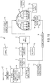
- FIG. 5 is a schematic diagram of an exemplary wired sensor system or array 50 that can be employed in the ECS of FIGS. 1A-1B .
- the system or array 50 may include a plurality of sensors 51 that can take the place of one or more of the individual sensors 12 in FIGS. 1A-1B .
- the controller 11 can communicate with various components of the ECS as described above. From the sensors 51, sensor responses or contaminant signals (i.e., resistance signals) can be sent, via a wired circuit to the controller 11.
- the controller 11 may send signals to the sensor(s) to initiate operational checks, may send signals to initiate a reading if not operating in a continuous mode, or may tell the sensor(s) to increase sampling frequency when the controller determines that an increased frequency is required for system control.
- the circuitry can provide multiple adjustable excitation voltages for an electronic gas sensor array and can provide data collection from the same gas sensor array for either ECS control or reporting to a higher level ECS controller.
- the microcontroller 11 can, via a host 59 (e.g., an ECS controller), provide an external host serial interface 58 (RS485, RS422, RS232, CANBUS etc) with signals for reporting of status or data to other processing units in the ECS system.
- a digital to analog converter (DAC) 52 can provide the conversion of a digital voltage value to an analog voltage.
- the DAC 52 is depicted as having, for example, eight channels of digital to analog conversion. The number of channels can be adjusted for each system requirement.
- firmware in the microcontroller 11 can use a non-proprietary serial interface (SPI, I2C etc) 55 to send digital update data to each channel of the DAC 52.
- SPI non-proprietary serial interface
- I2C I2C etc
- the process of changing a digital value to analog value may not be "noiseless” and voltage transients can be expected from one or more of the outputs of the DAC 52.
- a low pass analog filter (LPF) 53 can be inserted to reduce the voltage transient while still giving adequate waveform fidelity for the sensor excitation.
- an analog buffer amplifier 54 can be used to give a stable low impedance drive to the sensor excitation input.
- Each sensor 51 can have processing electronics that will convert the process variable and provide electronics to allow for a multi-drop serial interface 57 to be used to collect the various sensor data.
- firmware in the microcontroller 11 can use the non-proprietary serial interface (SPI, I2C etc.) 55 to "address" the channel of interest and “receive” the channel data.
- a serial bus 57 can use an "open collector” connection configuration which would require “pullup resistors” 56 to complete the interface connection.
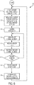
- FIG. 6 is a flow chart of an exemplary method 60 of supplying voltage to a sensor array according to the circuit of FIG. 5 .
- a voltage command may be sent to a digital-to-analog converter (DAC).
- DAC digital-to-analog converter
- a periodic voltage sent to a sensor may be delayed between periods to allow for voltage settling and/or resistance measuring settling.
- the controller11 firmware may set the number of the first sensor to be measured/converted, and may be set to address the first of a plurality of sensors (e.g., "n" number of sensors).
- the controller 11 may address the first of the plurality of sensors.
- a controller 11 may receive data from the first of the plurality of sensors.
- the controller 11 may be set to address the next of the plurality of sensors.
- step 67 if the next sensor is not more than or equal to the nth sensor, then the method returns to step 64. If in step 67, the next sensor is greater than the nth sensor, the method proceeds to a step 68 wherein the controller may process data from the sensor and/or send data to a host.
- the controller may generate new voltage commands.
- FIG. 7 is a schematic diagram of an exemplary wireless sensor system or array 70.
- the placement of system components/sensors is virtually unlimited with the proviso that the wireless signal can reach each of the components.
- Each component may require only a clear wireless path and electrical power.
- Complex control functions can be performed within each component and wireless communication will provide control and sensor data transfer.
- the system 70 may include a first sensor subsystem or subarray 50' and a second sensor subsystem or subarray 50" that can be employed in the ECS of FIGS. 1A-1B .
- the first subsystem 50' may be configured in a fashion similar to the system 50 in FIG. 5 . Accordingly, the first subsystem 50' may include a plurality of sensors 51' that can take the place of one or more of the individual sensors 12 in FIGS. 1A-1B . Each sensor can have a customized excitation voltage for increased sensor resolution of the contaminant being measured.
- a controller 11' can communicate with various components of the ECS as described above. From the sensor(s) 51', sensor responses or contaminant signals (i.e., resistance signals) can be sent, via a wireless signal, to the controller 72. Alternatively, the sensor(s) 51' may contain an internal wireless circuit. Wireless components will potentially enable changes in the physical placement of ECS sensor and effector components without data cable changes.
- the controller 11' may send signals to the sensor(s) to initiate operational checks, may send signals to initiate a reading if not operating in a continuous mode, or may tell the sensor(s) to increase sampling frequency when the controller determines that an increased frequency is required for system control.
- the first subsystem 50' may further include, with respect to each sensor 51', a respective digital to analog converter 52', a low pass analog filter 53', and an analog buffer amplifier 54', of which one or more of the foregoing can be similar in configuration and function as the digital to analog converter 52, the low pass analog filter 53, and the analog buffer amplifier 54 in FIG. 5 .
- the second subsystem 50" may include only a single sensor 51" that can take the place of one or more of the individual sensors 12 in FIGS. 1A-1B .
- the second subsystem 50" may include a plurality of sensors, such as that in the first subsystem 50'.
- a controller 11" can communicate with various components of the ECS as described above. From the sensor 51", sensor responses or contaminant signals (i.e., resistance signals) can be sent, via a wireless signal, to the controller 11".
- the sensor 51" may contain an internal wireless circuit.
- the controller 11" may send signals to the sensor to initiate operational checks, may send signals to initiate a reading if not operating in a continuous mode, or may tell the sensor to increase sampling frequency when the controller determines that an increased frequency is required for system control.
- the second subsystem 50" may further include, with respect to the sensor 51", a respective digital to analog converter 52", a low pass analog filter 53", and an analog buffer amplifier 54", of which one or more of the foregoing can be similar in configuration and function as the digital to analog converter 52, the low pass analog filter 53, and the analog buffer amplifier 54 in FIG. 5 .
- a wireless connection(s) 71 can be a connection to the "cloud services” 75.
- the "cloud services” 75 may tie all the system components together and can:
- a wireless connection(s) 74 may allow for redundant sensor connections and wireless data paths if selected appropriately. For example, if the first subsystem 50' is in close proximity to the second subsystem 50" Bluetooth could be used to establish a data transfer channel between the first and second subsystems. If the first and second subsystems 50', 50" are tied to the "cloud services" 75 with Wi-Fi and if one of the subsystems 50, 50" loses Wi-Fi communications with the "cloud services", the other subsystem could get sensor data from the former, via Bluetooth 74, and transmit to "cloud services”. There can be any number of subsystems in the system.
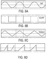
- the varying voltage signals to the sensor(s) 51 can be in various non-linear forms, such as sinusoidal, square, and sawtooth.
- a varying voltage is being provided in a continuous, multiple sweeping fashion over a range of voltages.
- the voltage signal can be a combination of sawtooth and square (i.e., modified sawtooth).
- the modified sawtooth waveform can allow for control parameters of peak excitation voltage, rate of change of excitation voltage, and the "off or sensor rest time".
- the peak voltage amplitude is to control the maximum excitation voltage applied to the sensor.
- the rate of change of applied excitation voltage gives the sensor the necessary "settling time” for repeatable sensor outputs.
- the "off or sensor rest time” is to allow the sensor to re-establish a new baseline before the start of the new scan.
- the selection of the three control parameters can allow for sensor measurement cycles from fractions of seconds to tens of seconds.
- the DAC can allow for stable and repeatable voltage excitation of the sensor.
- the frequency of the waveform can be determined by the time required for ramping plus the time required to provide the sensor with an adequate recovery or rest period in which the sensor reaches a stable baseline resistance. This baseline, though stable, may shift with time due to sensor contamination, thermal shift, aging of the resistivity of the semiconductor, or other unforeseen factors that may affect sensor performance.
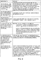
- FIG. 9 is an exemplary algorithm that describes potential corrective action that can be taken by the controller upon its receipt of a sensor signal.
Landscapes
- Chemical & Material Sciences (AREA)
- Health & Medical Sciences (AREA)
- Engineering & Computer Science (AREA)
- Life Sciences & Earth Sciences (AREA)
- General Health & Medical Sciences (AREA)
- Analytical Chemistry (AREA)
- Pathology (AREA)
- Immunology (AREA)
- General Physics & Mathematics (AREA)
- Biochemistry (AREA)
- Physics & Mathematics (AREA)
- Food Science & Technology (AREA)
- Medicinal Chemistry (AREA)
- Combustion & Propulsion (AREA)
- Aviation & Aerospace Engineering (AREA)
- Pulmonology (AREA)
- Chemical Kinetics & Catalysis (AREA)
- Electrochemistry (AREA)
- Air Conditioning Control Device (AREA)
Claims (7)
- Klimasteuersystem (ECS) (10), das Verunreinigungen in einer Zufuhrluft, die in eine Umgebung (14) strömt, aufweist, das Folgendes umfasst:eine Außenluftverunreinigungskomponente (12), die Verunreinigungen in Außenluft erfasst, wobei die Außenluftverunreinigungskomponente sich stromaufwärts der Umgebung (14) befindet;eine Rezirkulationsluftverunreinigungskomponente (12), die Verunreinigungen in Rezirkulationsluft, die durch die Umgebung (14) zugeführt wird, erfasst, wobei die Rezirkulationsluftverunreinigungskomponente sich stromabwärts der Umgebung (14) befindet; undeine Steuereinheit (11) in Kommunikation mit den Komponenten und einer Spannungsversorgung; dadurch gekennzeichnet, dassdie Spannungsversorgung eine nichtlinear veränderbare Spannung in einer kontinuierlichen Mehrfachdurchstimmweise über einen Bereich von Spannungen zu mindestens einer der Komponenten liefert;wobei
die Steuereinheit (11) aufgrund eines gemessenen Widerstands von mindestens einer der Komponenten, der einen Schwellenwert überschreitet, einen Außenluftstrom von außerhalb der Umgebung (4) und/oder einen Rezirkulationsluftstrom in das ECS (10) variiert, wobei sich der Schwellenwert auf eine Spannung bezieht. - System nach Anspruch 1, wobei die Außenluftverunreinigungskomponente ein einzelner Sensor ist.
- System nach Anspruch 1, wobei die Außenluftverunreinigungskomponente eine Sensoranordnung ist.
- System nach Anspruch 1, wobei die Rezirkulationsluftverunreinigungskomponente ein einzelner Sensor ist.
- System nach Anspruch 1, wobei die Rezirkulationsluftverunreinigungskomponente eine Sensoranordnung ist.
- System nach Anspruch 1, wobei die variierende Spannung in der Form einer Sinuskurve oder einer Rechteckkurve oder einer Sägezahnkurve oder einer modifizierten Sägezahnkurve vorliegt.
- System nach Anspruch 1, wobei der gemessene Widerstand ein Abfall eines Widerstands von einem Referenzwiderstand ist.
Priority Applications (1)
| Application Number | Priority Date | Filing Date | Title |
|---|---|---|---|
| EP19206769.2A EP3640138B1 (de) | 2016-10-31 | 2017-10-24 | Einstellbarer sensor oder sensornetzwerk zur selektiven verbesserung der identifikation von ausgewählten chemischen spezies |
Applications Claiming Priority (1)
| Application Number | Priority Date | Filing Date | Title |
|---|---|---|---|
| US15/339,405 US10329022B2 (en) | 2016-10-31 | 2016-10-31 | Adjustable sensor or sensor network to selectively enhance identification of select chemical species |
Related Child Applications (2)
| Application Number | Title | Priority Date | Filing Date |
|---|---|---|---|
| EP19206769.2A Division EP3640138B1 (de) | 2016-10-31 | 2017-10-24 | Einstellbarer sensor oder sensornetzwerk zur selektiven verbesserung der identifikation von ausgewählten chemischen spezies |
| EP19206769.2A Division-Into EP3640138B1 (de) | 2016-10-31 | 2017-10-24 | Einstellbarer sensor oder sensornetzwerk zur selektiven verbesserung der identifikation von ausgewählten chemischen spezies |
Publications (2)
| Publication Number | Publication Date |
|---|---|
| EP3315410A1 EP3315410A1 (de) | 2018-05-02 |
| EP3315410B1 true EP3315410B1 (de) | 2019-12-18 |
Family
ID=60190611
Family Applications (2)
| Application Number | Title | Priority Date | Filing Date |
|---|---|---|---|
| EP17198105.3A Active EP3315410B1 (de) | 2016-10-31 | 2017-10-24 | Einstellbarer sensor oder sensornetzwerk zur selektiven verbesserung der identifikation von ausgewählten chemischen spezies |
| EP19206769.2A Active EP3640138B1 (de) | 2016-10-31 | 2017-10-24 | Einstellbarer sensor oder sensornetzwerk zur selektiven verbesserung der identifikation von ausgewählten chemischen spezies |
Family Applications After (1)
| Application Number | Title | Priority Date | Filing Date |
|---|---|---|---|
| EP19206769.2A Active EP3640138B1 (de) | 2016-10-31 | 2017-10-24 | Einstellbarer sensor oder sensornetzwerk zur selektiven verbesserung der identifikation von ausgewählten chemischen spezies |
Country Status (2)
| Country | Link |
|---|---|
| US (1) | US10329022B2 (de) |
| EP (2) | EP3315410B1 (de) |
Families Citing this family (17)
| Publication number | Priority date | Publication date | Assignee | Title |
|---|---|---|---|---|
| US10737791B2 (en) * | 2017-10-04 | 2020-08-11 | The Boeing Company | Aerospace vehicle environmental control system |
| DE102017128338A1 (de) * | 2017-11-29 | 2019-05-29 | Airbus Operations Gmbh | Klimatisierungssystem für ein Luftfahrzeug |
| CN109353524A (zh) * | 2018-09-29 | 2019-02-19 | 北京航空航天大学 | 一种机载热管理系统及方法 |
| US11584540B2 (en) | 2019-04-05 | 2023-02-21 | Hamilton Sundstrand Corporation | Air quality sensors and methods of monitoring air quality |
| US11460444B2 (en) * | 2019-04-23 | 2022-10-04 | Pall Corporation | Aircraft air contaminant analyzer and method of use |
| US11465766B2 (en) * | 2019-06-28 | 2022-10-11 | The Boeing Company | Systems and methods for cooling and generating power on high speed flight vehicles |
| US11162933B2 (en) * | 2019-09-11 | 2021-11-02 | Haier Us Appliance Solutions, Inc. | System and method for detecting heavy metals in a fluid |
| US11796523B2 (en) | 2019-10-21 | 2023-10-24 | Gentex Corporation | Vapor and particulate sensor system for aerospace |
| CN111707842B (zh) * | 2020-06-28 | 2022-03-29 | 中车大连机车车辆有限公司 | 一种基于rs485串口的频率信号生成方法及转速系统测试方法 |
| US11635312B2 (en) | 2020-07-06 | 2023-04-25 | Honeywell International Inc. | Systems and methods for remote sensor calibration |
| US11851205B2 (en) * | 2020-07-06 | 2023-12-26 | Honeywell International Inc. | Air quality monitoring |
| US20220080077A1 (en) * | 2020-09-17 | 2022-03-17 | International Truck Intellectual Property Company, Llc | Occupant respiration isolation system |
| US12071246B2 (en) * | 2020-09-21 | 2024-08-27 | B/E Aerospace, Inc. | Air flow management |
| EP4001613B1 (de) | 2020-11-23 | 2024-06-19 | The Boeing Company | Verfahren und systeme zur erzeugung von strom und zur wärmeverwaltung mit doppelschleifenarchitektur |
| EP4001599B8 (de) | 2020-11-23 | 2023-04-12 | The Boeing Company | Verfahren und systeme zur leistungs- und wärmeverwaltung mit kombinierter zyklusarchitektur |
| US11893834B2 (en) * | 2021-01-27 | 2024-02-06 | Honeywell International Inc. | Supply air contamination detection |
| US12098984B2 (en) | 2021-04-02 | 2024-09-24 | Honeywell International Inc. | Supply air contamination sensor |
Family Cites Families (14)
| Publication number | Priority date | Publication date | Assignee | Title |
|---|---|---|---|---|
| DE4042557C2 (de) | 1990-12-06 | 1996-11-28 | Lehmann Martin | Verfahren zur Analyse von Gasproben und Analyseanordnung |
| KR960031987A (ko) | 1995-02-24 | 1996-09-17 | 구자홍 | 가스(gas) 센싱소자의 구조 및 제조방법 |
| US5571401A (en) | 1995-03-27 | 1996-11-05 | California Institute Of Technology | Sensor arrays for detecting analytes in fluids |
| US6493638B1 (en) | 2000-03-01 | 2002-12-10 | Raytheon Company | Sensor apparatus for measuring volatile organic compounds |
| US6711470B1 (en) | 2000-11-16 | 2004-03-23 | Bechtel Bwxt Idaho, Llc | Method, system and apparatus for monitoring and adjusting the quality of indoor air |
| US7052525B2 (en) | 2002-08-13 | 2006-05-30 | Ensco, Inc. | Vehicle integrated protective system |
| US7597788B2 (en) * | 2004-07-20 | 2009-10-06 | Applied Nanotech Holdings, Inc. | Oxygen-chemical agent sensor |
| US7950271B2 (en) | 2005-03-18 | 2011-05-31 | Applied Nanotech Holdings, Inc. | Gated beta-molybdenum oxide sensor |
| JP4883624B2 (ja) | 2006-11-18 | 2012-02-22 | 独立行政法人産業技術総合研究所 | 高感度ガスセンサ及びその製造方法 |
| GB0718299D0 (en) | 2007-09-19 | 2007-10-31 | Univ Bristol | Gas sensor |
| DE102010001624A1 (de) | 2010-02-05 | 2011-08-11 | Robert Bosch GmbH, 70469 | Verfahren zur Detektion von zwei oder mehr Gasspezies |
| TWI445958B (zh) | 2012-02-09 | 2014-07-21 | Ind Tech Res Inst | 氣體檢測系統、裝置及方法 |
| WO2014070780A1 (en) | 2012-10-29 | 2014-05-08 | University Of Utah Research Foundation | Functionalized nanotube sensors and related methods |
| US9957052B2 (en) | 2015-01-27 | 2018-05-01 | Honeywell International Inc. | Aircraft environmental control system that optimizes the proportion of outside air from engines, APU's, ground air sources and the recirculated cabin air to maintain occupant comfort and maximize fuel economy |
-
2016
- 2016-10-31 US US15/339,405 patent/US10329022B2/en not_active Expired - Fee Related
-
2017
- 2017-10-24 EP EP17198105.3A patent/EP3315410B1/de active Active
- 2017-10-24 EP EP19206769.2A patent/EP3640138B1/de active Active
Non-Patent Citations (1)
| Title |
|---|
| None * |
Also Published As
| Publication number | Publication date |
|---|---|
| EP3315410A1 (de) | 2018-05-02 |
| US10329022B2 (en) | 2019-06-25 |
| EP3640138B1 (de) | 2021-06-16 |
| US20180118351A1 (en) | 2018-05-03 |
| EP3640138A1 (de) | 2020-04-22 |
Similar Documents
| Publication | Publication Date | Title |
|---|---|---|
| EP3315410B1 (de) | Einstellbarer sensor oder sensornetzwerk zur selektiven verbesserung der identifikation von ausgewählten chemischen spezies | |
| US9957052B2 (en) | Aircraft environmental control system that optimizes the proportion of outside air from engines, APU's, ground air sources and the recirculated cabin air to maintain occupant comfort and maximize fuel economy | |
| US9902499B2 (en) | Human factors approach to control contaminant concentrations in aircraft supply air from engine and APU bleed air and ground air sources, and in recirculated air being delivered to aircraft cabins for the optimization of user experience and energy consumption | |
| US9884281B2 (en) | Method to use ultrafine particulate matter detection and measurement to control air supply system contaminant delivery to the aircraft cabin environment | |
| CN107635875B (zh) | 飞行器的机舱中的气流管理 | |
| EP3297918B1 (de) | Flugzeugluftqualitätüberwachungssystem und -verfahren | |
| US9505500B2 (en) | Inerting fuel systems, methods, and apparatuses | |
| Waters et al. | Measurements of indoor air quality on commercial transport aircraft | |
| US20200002009A1 (en) | Methodology that regulates the system components and optimizes the mixing of outside air in an adaptive environmental control system | |
| EP4036011B1 (de) | Versorgungsluftverschmutzungsdetektion | |
| DE10148606C1 (de) | Verfahren zum Überprüfen der Konvertierungsfähigkeit eines katalytischen Elementes zur Umwandlung von Ozon | |
| EP3296207B1 (de) | Verfahren zur verwendung von erkennung und messung von ultrafeinem teilchenförmigem material zur kontrolle von luftzufuhrsystemverunreinigungsabgaben an die flugzeugkabinenumgebung | |
| DE10142711A1 (de) | Vorrichtung mit einer Sensoranordnung zur Bestimmung der Umgebungsluftgüte sowie einer Anordnung von Ozonsensoren vor und hinter einem mit einem Katalysatormaterial beschichteten Kühler und Verfahren | |
| US20220316997A1 (en) | Supply air contamination sensor | |
| Fox | Air quality and comfort measurement aboard a commuter aircraft and solutions to improve perceived occupant comfort levels | |
| Stichternath | Pilot Measures against Cabin Air Contamination | |
| WO2026072026A2 (en) | Aircraft bleed air contaminant sensor system | |
| National Research Council | Air-Quality Measurement Techniques and Applications |
Legal Events
| Date | Code | Title | Description |
|---|---|---|---|
| PUAI | Public reference made under article 153(3) epc to a published international application that has entered the european phase |
Free format text: ORIGINAL CODE: 0009012 |
|
| STAA | Information on the status of an ep patent application or granted ep patent |
Free format text: STATUS: REQUEST FOR EXAMINATION WAS MADE |
|
| 17P | Request for examination filed |
Effective date: 20171024 |
|
| AK | Designated contracting states |
Kind code of ref document: A1 Designated state(s): AL AT BE BG CH CY CZ DE DK EE ES FI FR GB GR HR HU IE IS IT LI LT LU LV MC MK MT NL NO PL PT RO RS SE SI SK SM TR |
|
| AX | Request for extension of the european patent |
Extension state: BA ME |
|
| STAA | Information on the status of an ep patent application or granted ep patent |
Free format text: STATUS: EXAMINATION IS IN PROGRESS |
|
| RIC1 | Information provided on ipc code assigned before grant |
Ipc: G01N 33/00 20060101ALI20190129BHEP Ipc: B64D 13/06 20060101AFI20190129BHEP Ipc: G01N 27/12 20060101ALI20190129BHEP |
|
| 17Q | First examination report despatched |
Effective date: 20190219 |
|
| GRAP | Despatch of communication of intention to grant a patent |
Free format text: ORIGINAL CODE: EPIDOSNIGR1 |
|
| STAA | Information on the status of an ep patent application or granted ep patent |
Free format text: STATUS: GRANT OF PATENT IS INTENDED |
|
| INTG | Intention to grant announced |
Effective date: 20190724 |
|
| GRAS | Grant fee paid |
Free format text: ORIGINAL CODE: EPIDOSNIGR3 |
|
| GRAA | (expected) grant |
Free format text: ORIGINAL CODE: 0009210 |
|
| STAA | Information on the status of an ep patent application or granted ep patent |
Free format text: STATUS: THE PATENT HAS BEEN GRANTED |
|
| AK | Designated contracting states |
Kind code of ref document: B1 Designated state(s): AL AT BE BG CH CY CZ DE DK EE ES FI FR GB GR HR HU IE IS IT LI LT LU LV MC MK MT NL NO PL PT RO RS SE SI SK SM TR |
|
| REG | Reference to a national code |
Ref country code: CH Ref legal event code: EP |
|
| REG | Reference to a national code |
Ref country code: IE Ref legal event code: FG4D |
|
| REG | Reference to a national code |
Ref country code: DE Ref legal event code: R096 Ref document number: 602017009819 Country of ref document: DE |
|
| REG | Reference to a national code |
Ref country code: AT Ref legal event code: REF Ref document number: 1214338 Country of ref document: AT Kind code of ref document: T Effective date: 20200115 |
|
| REG | Reference to a national code |
Ref country code: NL Ref legal event code: MP Effective date: 20191218 |
|
| PG25 | Lapsed in a contracting state [announced via postgrant information from national office to epo] |
Ref country code: NO Free format text: LAPSE BECAUSE OF FAILURE TO SUBMIT A TRANSLATION OF THE DESCRIPTION OR TO PAY THE FEE WITHIN THE PRESCRIBED TIME-LIMIT Effective date: 20200318 Ref country code: GR Free format text: LAPSE BECAUSE OF FAILURE TO SUBMIT A TRANSLATION OF THE DESCRIPTION OR TO PAY THE FEE WITHIN THE PRESCRIBED TIME-LIMIT Effective date: 20200319 Ref country code: LT Free format text: LAPSE BECAUSE OF FAILURE TO SUBMIT A TRANSLATION OF THE DESCRIPTION OR TO PAY THE FEE WITHIN THE PRESCRIBED TIME-LIMIT Effective date: 20191218 Ref country code: LV Free format text: LAPSE BECAUSE OF FAILURE TO SUBMIT A TRANSLATION OF THE DESCRIPTION OR TO PAY THE FEE WITHIN THE PRESCRIBED TIME-LIMIT Effective date: 20191218 Ref country code: SE Free format text: LAPSE BECAUSE OF FAILURE TO SUBMIT A TRANSLATION OF THE DESCRIPTION OR TO PAY THE FEE WITHIN THE PRESCRIBED TIME-LIMIT Effective date: 20191218 Ref country code: BG Free format text: LAPSE BECAUSE OF FAILURE TO SUBMIT A TRANSLATION OF THE DESCRIPTION OR TO PAY THE FEE WITHIN THE PRESCRIBED TIME-LIMIT Effective date: 20200318 Ref country code: FI Free format text: LAPSE BECAUSE OF FAILURE TO SUBMIT A TRANSLATION OF THE DESCRIPTION OR TO PAY THE FEE WITHIN THE PRESCRIBED TIME-LIMIT Effective date: 20191218 |
|
| REG | Reference to a national code |
Ref country code: LT Ref legal event code: MG4D |
|
| PG25 | Lapsed in a contracting state [announced via postgrant information from national office to epo] |
Ref country code: RS Free format text: LAPSE BECAUSE OF FAILURE TO SUBMIT A TRANSLATION OF THE DESCRIPTION OR TO PAY THE FEE WITHIN THE PRESCRIBED TIME-LIMIT Effective date: 20191218 Ref country code: HR Free format text: LAPSE BECAUSE OF FAILURE TO SUBMIT A TRANSLATION OF THE DESCRIPTION OR TO PAY THE FEE WITHIN THE PRESCRIBED TIME-LIMIT Effective date: 20191218 |
|
| PG25 | Lapsed in a contracting state [announced via postgrant information from national office to epo] |
Ref country code: AL Free format text: LAPSE BECAUSE OF FAILURE TO SUBMIT A TRANSLATION OF THE DESCRIPTION OR TO PAY THE FEE WITHIN THE PRESCRIBED TIME-LIMIT Effective date: 20191218 |
|
| PG25 | Lapsed in a contracting state [announced via postgrant information from national office to epo] |
Ref country code: NL Free format text: LAPSE BECAUSE OF FAILURE TO SUBMIT A TRANSLATION OF THE DESCRIPTION OR TO PAY THE FEE WITHIN THE PRESCRIBED TIME-LIMIT Effective date: 20191218 Ref country code: EE Free format text: LAPSE BECAUSE OF FAILURE TO SUBMIT A TRANSLATION OF THE DESCRIPTION OR TO PAY THE FEE WITHIN THE PRESCRIBED TIME-LIMIT Effective date: 20191218 Ref country code: CZ Free format text: LAPSE BECAUSE OF FAILURE TO SUBMIT A TRANSLATION OF THE DESCRIPTION OR TO PAY THE FEE WITHIN THE PRESCRIBED TIME-LIMIT Effective date: 20191218 Ref country code: PT Free format text: LAPSE BECAUSE OF FAILURE TO SUBMIT A TRANSLATION OF THE DESCRIPTION OR TO PAY THE FEE WITHIN THE PRESCRIBED TIME-LIMIT Effective date: 20200513 Ref country code: RO Free format text: LAPSE BECAUSE OF FAILURE TO SUBMIT A TRANSLATION OF THE DESCRIPTION OR TO PAY THE FEE WITHIN THE PRESCRIBED TIME-LIMIT Effective date: 20191218 |
|
| PG25 | Lapsed in a contracting state [announced via postgrant information from national office to epo] |
Ref country code: SK Free format text: LAPSE BECAUSE OF FAILURE TO SUBMIT A TRANSLATION OF THE DESCRIPTION OR TO PAY THE FEE WITHIN THE PRESCRIBED TIME-LIMIT Effective date: 20191218 Ref country code: IS Free format text: LAPSE BECAUSE OF FAILURE TO SUBMIT A TRANSLATION OF THE DESCRIPTION OR TO PAY THE FEE WITHIN THE PRESCRIBED TIME-LIMIT Effective date: 20200418 Ref country code: SM Free format text: LAPSE BECAUSE OF FAILURE TO SUBMIT A TRANSLATION OF THE DESCRIPTION OR TO PAY THE FEE WITHIN THE PRESCRIBED TIME-LIMIT Effective date: 20191218 |
|
| REG | Reference to a national code |
Ref country code: DE Ref legal event code: R097 Ref document number: 602017009819 Country of ref document: DE |
|
| REG | Reference to a national code |
Ref country code: AT Ref legal event code: MK05 Ref document number: 1214338 Country of ref document: AT Kind code of ref document: T Effective date: 20191218 |
|
| PLBE | No opposition filed within time limit |
Free format text: ORIGINAL CODE: 0009261 |
|
| STAA | Information on the status of an ep patent application or granted ep patent |
Free format text: STATUS: NO OPPOSITION FILED WITHIN TIME LIMIT |
|
| PG25 | Lapsed in a contracting state [announced via postgrant information from national office to epo] |
Ref country code: ES Free format text: LAPSE BECAUSE OF FAILURE TO SUBMIT A TRANSLATION OF THE DESCRIPTION OR TO PAY THE FEE WITHIN THE PRESCRIBED TIME-LIMIT Effective date: 20191218 Ref country code: DK Free format text: LAPSE BECAUSE OF FAILURE TO SUBMIT A TRANSLATION OF THE DESCRIPTION OR TO PAY THE FEE WITHIN THE PRESCRIBED TIME-LIMIT Effective date: 20191218 |
|
| 26N | No opposition filed |
Effective date: 20200921 |
|
| PG25 | Lapsed in a contracting state [announced via postgrant information from national office to epo] |
Ref country code: SI Free format text: LAPSE BECAUSE OF FAILURE TO SUBMIT A TRANSLATION OF THE DESCRIPTION OR TO PAY THE FEE WITHIN THE PRESCRIBED TIME-LIMIT Effective date: 20191218 Ref country code: AT Free format text: LAPSE BECAUSE OF FAILURE TO SUBMIT A TRANSLATION OF THE DESCRIPTION OR TO PAY THE FEE WITHIN THE PRESCRIBED TIME-LIMIT Effective date: 20191218 |
|
| PG25 | Lapsed in a contracting state [announced via postgrant information from national office to epo] |
Ref country code: IT Free format text: LAPSE BECAUSE OF FAILURE TO SUBMIT A TRANSLATION OF THE DESCRIPTION OR TO PAY THE FEE WITHIN THE PRESCRIBED TIME-LIMIT Effective date: 20191218 |
|
| PG25 | Lapsed in a contracting state [announced via postgrant information from national office to epo] |
Ref country code: PL Free format text: LAPSE BECAUSE OF FAILURE TO SUBMIT A TRANSLATION OF THE DESCRIPTION OR TO PAY THE FEE WITHIN THE PRESCRIBED TIME-LIMIT Effective date: 20191218 |
|
| REG | Reference to a national code |
Ref country code: CH Ref legal event code: PL |
|
| PG25 | Lapsed in a contracting state [announced via postgrant information from national office to epo] |
Ref country code: LU Free format text: LAPSE BECAUSE OF NON-PAYMENT OF DUE FEES Effective date: 20201024 Ref country code: MC Free format text: LAPSE BECAUSE OF FAILURE TO SUBMIT A TRANSLATION OF THE DESCRIPTION OR TO PAY THE FEE WITHIN THE PRESCRIBED TIME-LIMIT Effective date: 20191218 |
|
| REG | Reference to a national code |
Ref country code: BE Ref legal event code: MM Effective date: 20201031 |
|
| PG25 | Lapsed in a contracting state [announced via postgrant information from national office to epo] |
Ref country code: FR Free format text: LAPSE BECAUSE OF NON-PAYMENT OF DUE FEES Effective date: 20201031 |
|
| PG25 | Lapsed in a contracting state [announced via postgrant information from national office to epo] |
Ref country code: LI Free format text: LAPSE BECAUSE OF NON-PAYMENT OF DUE FEES Effective date: 20201031 Ref country code: BE Free format text: LAPSE BECAUSE OF NON-PAYMENT OF DUE FEES Effective date: 20201031 Ref country code: CH Free format text: LAPSE BECAUSE OF NON-PAYMENT OF DUE FEES Effective date: 20201031 |
|
| PG25 | Lapsed in a contracting state [announced via postgrant information from national office to epo] |
Ref country code: IE Free format text: LAPSE BECAUSE OF NON-PAYMENT OF DUE FEES Effective date: 20201024 |
|
| PGFP | Annual fee paid to national office [announced via postgrant information from national office to epo] |
Ref country code: DE Payment date: 20211027 Year of fee payment: 5 Ref country code: GB Payment date: 20211026 Year of fee payment: 5 |
|
| PG25 | Lapsed in a contracting state [announced via postgrant information from national office to epo] |
Ref country code: TR Free format text: LAPSE BECAUSE OF FAILURE TO SUBMIT A TRANSLATION OF THE DESCRIPTION OR TO PAY THE FEE WITHIN THE PRESCRIBED TIME-LIMIT Effective date: 20191218 Ref country code: MT Free format text: LAPSE BECAUSE OF FAILURE TO SUBMIT A TRANSLATION OF THE DESCRIPTION OR TO PAY THE FEE WITHIN THE PRESCRIBED TIME-LIMIT Effective date: 20191218 Ref country code: CY Free format text: LAPSE BECAUSE OF FAILURE TO SUBMIT A TRANSLATION OF THE DESCRIPTION OR TO PAY THE FEE WITHIN THE PRESCRIBED TIME-LIMIT Effective date: 20191218 |
|
| PG25 | Lapsed in a contracting state [announced via postgrant information from national office to epo] |
Ref country code: MK Free format text: LAPSE BECAUSE OF FAILURE TO SUBMIT A TRANSLATION OF THE DESCRIPTION OR TO PAY THE FEE WITHIN THE PRESCRIBED TIME-LIMIT Effective date: 20191218 |
|
| REG | Reference to a national code |
Ref country code: DE Ref legal event code: R119 Ref document number: 602017009819 Country of ref document: DE |
|
| GBPC | Gb: european patent ceased through non-payment of renewal fee |
Effective date: 20221024 |
|
| P01 | Opt-out of the competence of the unified patent court (upc) registered |
Effective date: 20230525 |
|
| PG25 | Lapsed in a contracting state [announced via postgrant information from national office to epo] |
Ref country code: DE Free format text: LAPSE BECAUSE OF NON-PAYMENT OF DUE FEES Effective date: 20230503 |
|
| PG25 | Lapsed in a contracting state [announced via postgrant information from national office to epo] |
Ref country code: GB Free format text: LAPSE BECAUSE OF NON-PAYMENT OF DUE FEES Effective date: 20221024 |