EP3315720A2 - Rotor de compresseur d'une turbomachine - Google Patents
Rotor de compresseur d'une turbomachine Download PDFInfo
- Publication number
- EP3315720A2 EP3315720A2 EP17197040.3A EP17197040A EP3315720A2 EP 3315720 A2 EP3315720 A2 EP 3315720A2 EP 17197040 A EP17197040 A EP 17197040A EP 3315720 A2 EP3315720 A2 EP 3315720A2
- Authority
- EP
- European Patent Office
- Prior art keywords
- rotor
- hub
- blade
- blades
- compressor
- Prior art date
- Legal status (The legal status is an assumption and is not a legal conclusion. Google has not performed a legal analysis and makes no representation as to the accuracy of the status listed.)
- Withdrawn
Links
Images



Classifications
-
- F—MECHANICAL ENGINEERING; LIGHTING; HEATING; WEAPONS; BLASTING
- F01—MACHINES OR ENGINES IN GENERAL; ENGINE PLANTS IN GENERAL; STEAM ENGINES
- F01D—NON-POSITIVE DISPLACEMENT MACHINES OR ENGINES, e.g. STEAM TURBINES
- F01D5/00—Blades; Blade-carrying members; Heating, heat-insulating, cooling or antivibration means on the blades or the members
- F01D5/02—Blade-carrying members, e.g. rotors
-
- F—MECHANICAL ENGINEERING; LIGHTING; HEATING; WEAPONS; BLASTING
- F04—POSITIVE - DISPLACEMENT MACHINES FOR LIQUIDS; PUMPS FOR LIQUIDS OR ELASTIC FLUIDS
- F04D—NON-POSITIVE-DISPLACEMENT PUMPS
- F04D29/00—Details, component parts, or accessories
- F04D29/26—Rotors specially for elastic fluids
- F04D29/32—Rotors specially for elastic fluids for axial flow pumps
- F04D29/321—Rotors specially for elastic fluids for axial flow pumps for axial flow compressors
- F04D29/324—Blades
-
- F—MECHANICAL ENGINEERING; LIGHTING; HEATING; WEAPONS; BLASTING
- F01—MACHINES OR ENGINES IN GENERAL; ENGINE PLANTS IN GENERAL; STEAM ENGINES
- F01D—NON-POSITIVE DISPLACEMENT MACHINES OR ENGINES, e.g. STEAM TURBINES
- F01D5/00—Blades; Blade-carrying members; Heating, heat-insulating, cooling or antivibration means on the blades or the members
- F01D5/12—Blades
- F01D5/14—Form or construction
-
- F—MECHANICAL ENGINEERING; LIGHTING; HEATING; WEAPONS; BLASTING
- F01—MACHINES OR ENGINES IN GENERAL; ENGINE PLANTS IN GENERAL; STEAM ENGINES
- F01D—NON-POSITIVE DISPLACEMENT MACHINES OR ENGINES, e.g. STEAM TURBINES
- F01D5/00—Blades; Blade-carrying members; Heating, heat-insulating, cooling or antivibration means on the blades or the members
- F01D5/12—Blades
- F01D5/14—Form or construction
- F01D5/147—Construction, i.e. structural features, e.g. of weight-saving hollow blades
-
- F—MECHANICAL ENGINEERING; LIGHTING; HEATING; WEAPONS; BLASTING
- F01—MACHINES OR ENGINES IN GENERAL; ENGINE PLANTS IN GENERAL; STEAM ENGINES
- F01D—NON-POSITIVE DISPLACEMENT MACHINES OR ENGINES, e.g. STEAM TURBINES
- F01D5/00—Blades; Blade-carrying members; Heating, heat-insulating, cooling or antivibration means on the blades or the members
- F01D5/30—Fixing blades to rotors; Blade roots ; Blade spacers
- F01D5/3061—Fixing blades to rotors; Blade roots ; Blade spacers by welding, brazing
-
- F—MECHANICAL ENGINEERING; LIGHTING; HEATING; WEAPONS; BLASTING
- F01—MACHINES OR ENGINES IN GENERAL; ENGINE PLANTS IN GENERAL; STEAM ENGINES
- F01D—NON-POSITIVE DISPLACEMENT MACHINES OR ENGINES, e.g. STEAM TURBINES
- F01D5/00—Blades; Blade-carrying members; Heating, heat-insulating, cooling or antivibration means on the blades or the members
- F01D5/34—Rotor-blade aggregates of unitary construction, e.g. formed of sheet laminae
-
- F—MECHANICAL ENGINEERING; LIGHTING; HEATING; WEAPONS; BLASTING
- F04—POSITIVE - DISPLACEMENT MACHINES FOR LIQUIDS; PUMPS FOR LIQUIDS OR ELASTIC FLUIDS
- F04D—NON-POSITIVE-DISPLACEMENT PUMPS
- F04D19/00—Axial-flow pumps
-
- F—MECHANICAL ENGINEERING; LIGHTING; HEATING; WEAPONS; BLASTING
- F04—POSITIVE - DISPLACEMENT MACHINES FOR LIQUIDS; PUMPS FOR LIQUIDS OR ELASTIC FLUIDS
- F04D—NON-POSITIVE-DISPLACEMENT PUMPS
- F04D29/00—Details, component parts, or accessories
- F04D29/26—Rotors specially for elastic fluids
- F04D29/28—Rotors specially for elastic fluids for centrifugal or helico-centrifugal pumps for radial-flow or helico-centrifugal pumps
- F04D29/284—Rotors specially for elastic fluids for centrifugal or helico-centrifugal pumps for radial-flow or helico-centrifugal pumps for compressors
-
- F—MECHANICAL ENGINEERING; LIGHTING; HEATING; WEAPONS; BLASTING
- F05—INDEXING SCHEMES RELATING TO ENGINES OR PUMPS IN VARIOUS SUBCLASSES OF CLASSES F01-F04
- F05D—INDEXING SCHEME FOR ASPECTS RELATING TO NON-POSITIVE-DISPLACEMENT MACHINES OR ENGINES, GAS-TURBINES OR JET-PROPULSION PLANTS
- F05D2250/00—Geometry
- F05D2250/10—Two-dimensional
- F05D2250/14—Two-dimensional elliptical
Definitions
- the invention relates to a compressor rotor of a turbomachine according to the preamble of patent claim 1.
- the present invention has for its object to provide a compressor rotor of a turbomachine, which has an improved robustness against damage caused by foreign bodies.
- the invention contemplates a compressor rotor of a turbomachine having a rotor disk, a rotor hub, and a plurality of blades disposed on the rotor hub and extending radially outward.
- the rotor hub has an axially forward leading edge, an axially trailing trailing edge, a hub top, a front hub bottom, and a rear hub bottom.
- the front hub base extends on the underside of the rotor hub from the leading edge in the direction of the rotor disk and passes into this.
- the rear hub base extends on the underside of the rotor hub from the trailing edge in the direction of the rotor disk and passes into this.
- the front hub base and / or the rear hub base is contoured in the circumferential direction of the rotor hub in such a way that it forms an indentation in each case in the region below a rotor blade. Accordingly, the rotor hub in each case in the region of a rotor blade is reduced in thickness, wherein the thickness of the rotor hub, the radial distance between the hub top and the hub base is called.
- front edge and the rear edge can also be formed flat, in which case they form a front end face and a rear end face.
- leading edge and trailing edge are thus to be understood in the sense of the present invention such that they can designate both an edged edge and a flat end face.
- the invention can be realized both on axial compressors and on radial compressors.
- An embodiment of the invention provides that the rotor hub, starting from the leading edge and / or starting from the trailing edge in each case below a blade forms a recess.
- the indentations are thus formed respectively at the edges of the rotor hub and adjacent to the hub base. This ensures that internal compressive stresses are introduced to a particular extent at the blade leading edge or the blade trailing edge in the blades.
- a further embodiment of the invention provides that the indentations are each concave (when viewed in the circumferential direction) and thereby extend in the axial direction in the direction of the rotor disk. It can be provided that the depth of the recess decreases in the direction of the rotor disk until it has disappeared completely at the latest at the axial height of the rotor disk.
- the indentations are accordingly approximately trench-shaped, wherein the trench extends from the leading edge or trailing edge in the axial direction and thereby decreases in the direction of the rotor disk in its depth.
- the indentation and the maximum blade root thickness in the circumferential direction cover angular ranges that overlap.
- the indentation and the maximum blade root thickness overlap when pushed over each other in the radial direction.
- the blade root thickness is defined such that it includes the thickness (ie the distance in the circumferential direction between the suction side and the pressure side) of the blade plus the extent in the circumferential direction of the two rounding, also referred to as "fillet", which includes the transition from the actual blade to Rotor hub form.
- the maximum blade thickness, the circumferentially extending portion of a blade which extends from the rounding of the blade on the suction side to the rounding of the blade on the pressure side of the blade.
- An embodiment of the invention provides that the indentations extend in the circumferential direction over a length which is between half and five times the maximum Schaufelfußdicke, in particular between the maximum Schaufelfußdicke and three times the maximum Schaufelfußdicke. This should apply to at least one section through the hub in a plane transverse to the axis of rotation, in particular at the front edge and / or the rear edge of the rotor hub.
- the maximum thickness reduction of the rotor hub provided by an indentation ranges between 5% and 30%, in particular between 10% and 20% to the thickness of the rotor hub in the middle between two adjacent blades.
- An embodiment of the invention provides that the contouring of the front hub base side and / or the contouring of the rear hub base in the circumferential direction takes place periodically in the sense that the indentations on all blades have the same relative position to the rotor blade.
- the indentations are each formed symmetrically with respect to the rotor blades.
- the contouring of the front hub base side and / or the contouring of the rear hub base in the circumferential direction is non-periodic in the sense that the indentations on at least some of the rotor blades differ with respect to the relative position to the rotor blade. As a result, such blades have a different natural frequency.
- Such a configuration is therefore associated with the advantage of detuning the system and thus avoiding resonance conditions. The detuning of the system prevents energy from being transported to other blades at the natural frequency, or this effect is reduced.
- a detuning of the system by a non-periodic arrangement of the recesses with respect to the blades is particularly advantageous in compressor rotors, which have little damping in the transition between blade and Rotor hub exhibit.
- the compressor rotor is the compressor rotor of a radial compressor and integral radial compressor impeller.
- an embodiment of the invention provides that contouring is non-periodic such that the relative position of the indentations to the respective blade for a group of adjacent blades migrates from blade to blade by the same amount in the circumferential direction.
- the term "in the circumferential direction” also includes a displacement against the circumferential direction.
- the relative position of the indentations to the respective blade migrates circumferentially in a considered group of adjacent blades such that, if d2 is the maximum blade root thickness and n is the number of blades of the considered group, the indentations from blade to blade are shifted by an angle in the circumferential direction, which is equal to d2 / n.
- a group of adjacent blades has, for example, between three and seven, in particular between four and six blades.
- the blade-to-blade depression is shifted by 25% of the maximum blade root thickness. It goes without saying that the indentation in each blade is at least partially formed in the region below the blades. In the circumferential direction of the compressor rotor, such groups of detuned blades can adjoin one another and together form the compressor blade.
- the invention relates according to a further aspect of the invention, a compressor rotor with the features of claim 14.
- the front Hub base and / or the rear hub base are contoured such that for each meridional section through the rotor hub, that in the meridional section the boundary line of the front hub base at least adjacent to the front edge and / or the boundary line of the rear hub base at least adjacent to the trailing edge by an ellipse writable is.
- This aspect of the invention thus provides a very specific course of the boundary line of the front hub base and / or the rear hub base adjacent to the leading edge or trailing edge, namely an elliptical course, i. a gradient in which the boundary line lies at least partially on an ellipse.
- an elliptical course i. a gradient in which the boundary line lies at least partially on an ellipse.
- a meridional section is taken along the axial and radial directions and contains the axis of rotation.
- the statement that said feature applies to each meridional section through the rotor hub means that the described design of the hub base is circumferentially symmetric.
- the boundary line is elliptical in its entire length to the transition into the rotor disk.
- a further embodiment may provide that the boundary line on the hub base extends from the leading edge or trailing edge over a length in the direction of the rotor disk whose axial component is in the range between 10% and 30% of the axial extent (between leading edge and trailing edge) of the rotor hub , This range refers to the axial component, i. the projection of the boundary line in the axial direction. This is considered because the boundary line also has a radial component in the direction of the axis of rotation.
- a compressor rotor in the sense of the present invention is each rotor of a compressor stage of a turbomachine.
- the compressor rotor may be a fan rotor, a rotor of a low-pressure compressor, a rotor of a medium-pressure compressor or a rotor of a high-pressure compressor.
- a turbomachine in the sense of the present invention is, for example, an aircraft engine, in particular a turbofan engine, or a gas turbine for generating energy.
- FIG. 1 1 schematically shows a turbofan engine 100 having a fan stage with a fan 10 as a low-pressure compressor, a medium-pressure compressor 20, a high-pressure compressor 30, a combustion chamber 40, a high-pressure turbine 50, a medium-pressure turbine 60 and a low-pressure turbine 70.
- the medium-pressure compressor 20 and the high-pressure compressor 30 each have a plurality of compressor stages, each comprising a rotor and a stator.
- the turbofan engine 100 of FIG. 1 further comprises three separate shafts, a low pressure shaft 81 connecting the low pressure turbine 70 to the fan 10, a medium pressure shaft 82 connecting the medium pressure turbine 60 to the intermediate pressure compressor 20, and a high pressure shaft 83 connecting the high pressure turbine 50 to the high pressure compressor 30.
- this is only to be understood as an example.
- the turbofan engine did not have a medium pressure compressor and medium pressure turbine, only a low pressure shaft and a high pressure shaft would be present.
- the turbofan engine 100 has an engine nacelle 1, which comprises an inlet lip 14 and, on the inside, forms an engine inlet 11, which supplies incoming air to the fan 10.
- the fan 10 has a plurality of fan blades 101 connected to a fan disk 102.
- the annulus of the fan disk 102 forms the radially inner boundary of the flow path through the fan 10. Radially outside the flow path is limited by a fan housing 2. Upstream of the fan disk 102, a nose cone 103 is disposed.
- the turbofan engine 100 forms a secondary flow channel 4 and a primary flow channel 5.
- the primary flow channel 5 passes through the core engine (gas turbine) comprising the medium pressure compressor 20, the high pressure compressor 30, the combustor 40, the high pressure turbine 50, the medium pressure turbine 60, and the low pressure turbine 70.
- the medium-pressure compressor 20 and the high-pressure compressor 30 are surrounded by a peripheral housing 29, that on the inside forms an annular space surface which defines the primary flow channel 5 radially outward.
- Radially inside, the primary flow channel 5 is bounded by corresponding ring surfaces of the rotors and stators of the respective compressor stages or by the hub or hub connected to the elements of the corresponding drive shaft.
- a primary flow passes through the primary flow passage 5, which is also referred to as the main flow passage.
- the secondary flow channel 4 also referred to as bypass duct, bypass duct or bypass duct, passes in the operation of the turbofan engine 100 by the fan 10 sucked air past the core engine.
- the described components have a common axis of rotation 90.
- the axis of rotation 90 defines an axial direction of the turbofan engine.
- a radial direction of the turbofan engine is perpendicular to the axial direction.
- a compressor rotor i. the rotor of a compressor stage of importance, wherein one or more compressor rotors of the low pressure compressor, the medium pressure compressor or the high pressure compressor may be formed in the manner described below.
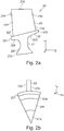
- FIG. 2a shows in meridional section and the FIG. 2b in a front view, ie in the flow direction, the basic structure of a compressor rotor 2.
- Die FIG. 2b shows in front view only a circular sector of the compressor rotor.
- the compressor rotor 20 has a rotor disk 21, a rotor hub 22 and a plurality of rotor blades 23.
- the rotor disk 21 is rotatable about an axis of rotation which extends in an axial direction x (eg the axis of rotation 90 of FIG FIG. 1 ).
- the rotor hub 22 forms the radially outer edge of the rotor disk 21 or is connected thereto.
- the rotor blades 23 each extend radially outward and are arranged at a distance from the rotor hub 22 in the circumferential direction. They form the blade ring of the compressor rotor 2.
- the description of the compressor rotor 20 is made in a cylindrical coordinate system having the coordinates x, r and ⁇ .
- x indicates the axial direction
- r the radial direction
- ⁇ the angle in the circumferential direction.
- the radial direction points radially outward.
- Terms such as “ahead”, “behind”, “front” and “rear” always refer to the axial direction, which is substantially equal to the flow direction.
- the rotor blades 23 have a leading edge 231, a trailing edge 232, a pressure side 234, a suction side 235 and a blade tip 236.
- a separate blade root is not provided in the illustrated embodiment, since the compressor rotor is designed in BLISK design, ie rotor disk 21, rotor hub 22 and the blades 23 are integrally formed. However, this is not necessarily the case.
- the blades may each have a blade root mounted in a corresponding recess in the rotor hub.
- the compressor rotor is designed in BLING construction, wherein the rotor hub 22 and the rotor blades 23 are integrally formed.
- the rotor hub 22 which may also be referred to as a paddle platform, has a leading edge 221, a trailing edge 222, and a hub top 223 extending from the leading edge 221 to the trailing edge 222 and from which the blades 23 protrude.
- the hub top 223 forms a rim surface which, during operation of the compressor rotor, defines the flow channel radially inward through the blade ring.
- the rotor hub 22 further includes a front hub bottom 224 which extends on the underside of the rotor hub 22 from the front edge 221 in the direction of the rotor disk 21 and merges into this, and a rear hub base 225, located on the underside of the rotor hub 22 of the trailing edge 222 extends in the direction of the rotor disk 21 and merges into it.
- the rotor disk 21 has a disk-shaped region 211 and a disk base 212.
- FIG. 3 shows schematically in a front view a first embodiment. As with the FIG. 2b Is at the FIG. 3 only a circular sector is shown. It is provided that the front hub underside 224 is contoured in the circumferential direction of the rotor hub 22 such that it forms an indentation 40 in each case in the region below a rotor blade 23. In the region of the recess 40, the thickness of the rotor hub 22 is reduced accordingly. As a result of the reduction in thickness in the area of the rotor blade 23, the rotor hub 22 is softer there, so that the rotor blade 23 becomes stronger during rotation due to the centrifugal forces that occur and can introduce increased internal compressive stresses into the blade 23, in particular into the front edge of the blade 23 ,
- the indentation 40 extends both in the circumferential direction and in the axial direction.
- the surface of the indentation 40 accordingly has a larger radius both in the circumferential direction and in the radial direction (ie radial Distance from the axis of rotation) than the areas on the hub bottom 224 that do not form a recess.
- the indentation 40 begins at the front edge 221 of the rotor hub and extends from there in the axial direction in the direction of the rotor disk 21. It can be provided that the depth of the indentation 40 decreases in the direction of the rotor disc 21 and it is completely disappeared from a certain axial extent (for example, after an axial extent which is in the range between 10% and 30% of the axial extent of the rotor hub 22 ). The softness achieved by the recess 40 is thus realized in particular in the edge region of the rotor hub 22.
- the indentation 40 is concave and can basically have any shape. It preferably has smooth transitions to the non-indented, adjacent areas of the hub bottom 224.
- the indentation 40 is formed in the region below the rotor blade 23 on the hub bottom side 224. This will be explained further below.
- the blade 23 has a blade thickness d1 defined by the distance between the suction side 235 and the pressure side 234. In the transition to the hub top 223 forms the blade on the suction side 235 and the pressure side 234 in a conventional manner a rounding 237, 238, also referred to as "fillet" on.
- the maximum blade root thickness d2 is the blade thickness d1 plus the thickness in the circumferential direction of the rounded portions 237, 238.
- the maximum blade root thickness d2 is thus the circumferentially extending portion of the blade 23 at its intersection with the grain surface 223, which extends from the rounding 237 on the suction side 235 to the rounding 238 on the pressure side 234 of the blade 23.
- the maximum blade root thickness d2 corresponds to an angular range ⁇ 1 of the polar angle ⁇ of the considered cylindrical coordinate system.
- an angular range ⁇ 2 corresponds to the recess 40, which extends from the beginning of the recess 40 to the end of the recess 40 in the circumferential direction. Since the indentation 40 is formed in the region below a blade 23, the indentation 40 and the maximum blade root thickness d2 overlap in the circumferential direction. This means that the angles ⁇ 1 and ⁇ 2 at least partially overlap. In other words, at least a portion of the indentation 40 lies in the radial direction below the maximum blade root thickness d2. It is not necessary that, as in the embodiment of FIG. 3 in that the angle ⁇ 1 is completely within the angle ⁇ 2. As long as there is any overlap, the indentation 40 lies in the area below a blade 23 in the sense of the present invention.
- such a recess in the region of the rear hub base 225 may be introduced into the rotor hub 22.
- elevated internal compressive stresses prevail, in particular in the region of the trailing edge of the blade 23.
- FIG. 4 shows an embodiment of the embodiment of the FIG. 3 equivalent.
- the FIG. 4 shows thereby compared with the FIG. 3 a larger circular sector of the rotor hub 22, so that a plurality of indentations 41, 42, 43 are shown.
- the indentations 41, 42, 43 are as in the FIG. 3 each centered below the associated blade 23 is arranged. They have the same relative position to the respective blade 23.
- the thickness of the rotor hub 22 changes in the region of an indentation 41, 42, 43. Since the depth of the indentation 41, 42, 43 changes in the axial direction, a change in thickness can always be considered quantitatively only for a section considered in a plane transverse to the axis of rotation.
- the change in thickness at the front edge 221 of the rotor hub 22 is shown.
- the thickness changes from a thickness d3 in the middle between two adjacent rotor blades 23 to a thickness d4.
- the reduction in thickness of the rotor hub 22 from d3 to d4 is, for example, in the range between 5% and 30%, in particular in the range between 10% and 20%, based on the thickness d3.
- the indentations 41, 42, 43 extend in the circumferential direction ⁇ , for example over a length which is between half (d2 / 2) and five times (5 * d2) maximum blade root thickness d2, in particular between the maximum blade root thickness (d2) and three times (d2). 3 * d2) maximum blade root thickness d2, wherein the maximum blade root thickness d2 as in relation to FIG. 3 is explained explained.
- FIG. 5 shows an embodiment in which the contouring of the front hub base 224 in the circumferential direction ⁇ is non-periodically in the sense that the Indentations on at least some of the blades differ in relative position to the blade.
- a non-periodic contouring takes place such that the relative position of the indentations to the respective blade for a group of adjacent blades migrates from blade to blade in the circumferential direction.
- the FIG. 5 hereby considers a group of four blades 23, of which three blades 23 are shown, in which the relative position of the associated indentations 44, 45, 46 changes from blade to blade and thereby moves in the circumferential direction ⁇ . If d2 is the maximum blade root thickness (which, as with respect to the FIG. 3 is defined) and when n is the number of blades of the considered group, the indentations from blade 23 to blade 23 are circumferentially displaced by an angle ⁇ equal to d2 divided by n.
- the recess 44 When in the FIG. 5 considered group of four blades, the recess 44 is arranged centered to the associated blade 23.
- FIG. 6 shows an embodiment which is characterized by a certain contouring of the front hub base and / or rear hub base.
- a compressor rotor 20 ' is provided, which has a rotor disk 21, a rotor hub 22 and a plurality of blades 23, wherein the Blades 23 each have a leading edge 231, a trailing edge 232, a pressure side 234, a suction side 235 and a blade tip 236.
- the rotor hub 22 has a front edge 221, a rear edge 222, a hub top 223, a front hub bottom 224, and a rear hub bottom 225.
- the rotor disk 21 has a disk shaped portion 211 and a disk base 212.
- the boundary line 226 of the front hub base 224 at least adjacent to the leading edge 221 is described by an ellipse.
- the boundary line 227 of the rear hub underside 225 can be described by an ellipse at least adjacent to the trailing edge 222.
- the contouring described is circumferentially symmetrical, that is, it applies to each meridional section through the rotor hub 22nd
- the boundary line 226 and / or the boundary line 227 is elliptical in its entire length up to the transition into the rotor disk 21 or its disk-shaped region 211.
- the boundary line 226 and / or the boundary line 227 is elliptical over only part of its length, for example via a section adjacent to the front edge 221 or rear edge 222 whose axial component is in the range between 10% and 30%. the axial extent of the rotor hub 22 (ie between the leading edge 221 and trailing edge 222) is located.
- FIG. 7 shows further circumferentially symmetric contouring of the rotor hub 22 in the hub bottom side.
- the front hub base 224 and / or the rear hub base 225 has a recess 228, 229 opposite a straight line curve shown in dashed lines, which extends circumferentially symmetrically.
- the softness of the rotor hub 22 in the region of the outer edges 221, 222 is generally increased.
- the present invention is not limited in its embodiment to the embodiments described above.
- the shape of the indentations in the Figures 3-5 merely to be understood as an example.
Landscapes
- Engineering & Computer Science (AREA)
- Mechanical Engineering (AREA)
- General Engineering & Computer Science (AREA)
- Architecture (AREA)
- Ceramic Engineering (AREA)
- Structures Of Non-Positive Displacement Pumps (AREA)
Applications Claiming Priority (1)
| Application Number | Priority Date | Filing Date | Title |
|---|---|---|---|
| DE102016120346.7A DE102016120346A1 (de) | 2016-10-25 | 2016-10-25 | Verdichterrotor einer Strömungsmaschine |
Publications (2)
| Publication Number | Publication Date |
|---|---|
| EP3315720A2 true EP3315720A2 (fr) | 2018-05-02 |
| EP3315720A3 EP3315720A3 (fr) | 2018-06-06 |
Family
ID=60138280
Family Applications (1)
| Application Number | Title | Priority Date | Filing Date |
|---|---|---|---|
| EP17197040.3A Withdrawn EP3315720A3 (fr) | 2016-10-25 | 2017-10-18 | Rotor de compresseur d'une turbomachine |
Country Status (3)
| Country | Link |
|---|---|
| US (1) | US10995768B2 (fr) |
| EP (1) | EP3315720A3 (fr) |
| DE (1) | DE102016120346A1 (fr) |
Families Citing this family (2)
| Publication number | Priority date | Publication date | Assignee | Title |
|---|---|---|---|---|
| US12228052B2 (en) * | 2023-07-19 | 2025-02-18 | Pratt & Whitney Canada Corp. | Integrally bladed rotor with increased rim bending stiffness |
| US12669060B2 (en) | 2024-03-05 | 2026-06-30 | General Electric Company | Airfoil rotor hub system having intentional frequency mistuning |
Citations (2)
| Publication number | Priority date | Publication date | Assignee | Title |
|---|---|---|---|---|
| US20130209260A1 (en) * | 2012-02-09 | 2013-08-15 | Paul Stone | Gas turbine engine rotor balancing |
| US20150292337A1 (en) * | 2014-04-11 | 2015-10-15 | Honeywell International Inc. | Components resistant to traveling wave vibration and methods for manufacturing the same |
Family Cites Families (11)
| Publication number | Priority date | Publication date | Assignee | Title |
|---|---|---|---|---|
| FR2674569A1 (fr) * | 1991-03-27 | 1992-10-02 | Snecma | Disque ailete monobloc avec amortissement des vibrations pour turbomachine. |
| US5292385A (en) * | 1991-12-18 | 1994-03-08 | Alliedsignal Inc. | Turbine rotor having improved rim durability |
| FR2874232B1 (fr) | 1998-07-28 | 2007-06-15 | Rolls Royce Plc Plc | Rotor metallique renforce de fibres. |
| US6354780B1 (en) | 2000-09-15 | 2002-03-12 | General Electric Company | Eccentric balanced blisk |
| US6857853B1 (en) * | 2003-08-13 | 2005-02-22 | General Electric Company | Conical tip shroud fillet for a turbine bucket |
| GB2411441B (en) | 2004-02-24 | 2006-04-19 | Rolls Royce Plc | Fan or compressor blisk |
| JP5030813B2 (ja) * | 2008-02-20 | 2012-09-19 | 三菱重工業株式会社 | ブリスク |
| DE102008052247A1 (de) * | 2008-10-18 | 2010-04-22 | Mtu Aero Engines Gmbh | Bauteil für eine Gasturbine und Verfahren zur Herstellung des Bauteils |
| GB2468722A (en) * | 2009-03-21 | 2010-09-22 | Warren Barratt Leigh | Carbon fibre wishbone comprising stress uniform fillet |
| GB0914060D0 (en) | 2009-08-12 | 2009-09-16 | Rolls Royce Plc | A rotor assembly for a gas turbine |
| US10557352B2 (en) * | 2014-09-09 | 2020-02-11 | Rolls-Royce Corporation | Piezoelectric damping rings |
-
2016
- 2016-10-25 DE DE102016120346.7A patent/DE102016120346A1/de not_active Withdrawn
-
2017
- 2017-10-18 EP EP17197040.3A patent/EP3315720A3/fr not_active Withdrawn
- 2017-10-20 US US15/789,078 patent/US10995768B2/en not_active Expired - Fee Related
Patent Citations (2)
| Publication number | Priority date | Publication date | Assignee | Title |
|---|---|---|---|---|
| US20130209260A1 (en) * | 2012-02-09 | 2013-08-15 | Paul Stone | Gas turbine engine rotor balancing |
| US20150292337A1 (en) * | 2014-04-11 | 2015-10-15 | Honeywell International Inc. | Components resistant to traveling wave vibration and methods for manufacturing the same |
Also Published As
| Publication number | Publication date |
|---|---|
| EP3315720A3 (fr) | 2018-06-06 |
| US10995768B2 (en) | 2021-05-04 |
| DE102016120346A1 (de) | 2018-04-26 |
| US20180112674A1 (en) | 2018-04-26 |
Similar Documents
| Publication | Publication Date | Title |
|---|---|---|
| EP2808559B1 (fr) | Ensemble structurel pour une turbomachine | |
| EP2165080B1 (fr) | Diffuseur pour compresseur radial | |
| EP2249043B1 (fr) | Compresseur ou pompe avec extraction de fluide | |
| EP2514975B1 (fr) | Turbomachine | |
| EP2226510B1 (fr) | Turbo compresseur ou pompe avec injection de fluide pour influencer la couche limite | |
| EP3428393B1 (fr) | Roue aubagée d'une turbomachine | |
| EP3404210B1 (fr) | Segment de grille d'aubes d'une turbomachine avec paroi de plateforme non-axisymétrique , grille d'aubes, canal d'aube, plateforme, turbomachine associés | |
| DE102008017844A1 (de) | Strömungsmaschine mit Fluid-Injektorbaugruppe | |
| EP2505783B1 (fr) | Rotor d'un étage de compresseur axial d'une turbomachine | |
| CH707543A2 (de) | Turbomaschine mit wirbelhemmender Dichtung. | |
| EP2808556B1 (fr) | Ensemble structurel pour une turbomachine | |
| CH708774A2 (de) | Turbinenschaufel mit einem Schaufelblatt mit Spitzenausrundung. | |
| WO2015197536A1 (fr) | Diffuseur pour compresseur radial | |
| WO2018060068A1 (fr) | Aubes à tracé en forme de s dans la direction d'écoulement pour des roues à aubes à type de construction radiale | |
| EP2597257B1 (fr) | Aubage | |
| EP2607625A1 (fr) | Turbomachine et étage de turbomachine | |
| WO2005116404A1 (fr) | Aube comportant une zone de transition | |
| DE102016124147B4 (de) | Innenkühlkonfigurationen in Turbinenrotorschaufeln | |
| EP3650709A1 (fr) | Dispositif diffuseur à aubes pour un compresseur radial | |
| WO2005088135A1 (fr) | Compresseur d'une turbine a gaz ainsi que turbine a gaz | |
| DE102016120346A1 (de) | Verdichterrotor einer Strömungsmaschine | |
| EP3327258A1 (fr) | Roue de guidage d'entrée pour une turbomachine | |
| EP3375977A1 (fr) | Contournage d'une plate-forme de grille d'aube | |
| DE102021109844A1 (de) | Gasturbinen-Schaufelanordnung | |
| EP3225789A1 (fr) | Ensemble de moteur avec carter de soufflante et diffuseur d'entrée |
Legal Events
| Date | Code | Title | Description |
|---|---|---|---|
| PUAI | Public reference made under article 153(3) epc to a published international application that has entered the european phase |
Free format text: ORIGINAL CODE: 0009012 |
|
| STAA | Information on the status of an ep patent application or granted ep patent |
Free format text: STATUS: THE APPLICATION HAS BEEN PUBLISHED |
|
| AK | Designated contracting states |
Kind code of ref document: A2 Designated state(s): AL AT BE BG CH CY CZ DE DK EE ES FI FR GB GR HR HU IE IS IT LI LT LU LV MC MK MT NL NO PL PT RO RS SE SI SK SM TR |
|
| AX | Request for extension of the european patent |
Extension state: BA ME |
|
| PUAL | Search report despatched |
Free format text: ORIGINAL CODE: 0009013 |
|
| AK | Designated contracting states |
Kind code of ref document: A3 Designated state(s): AL AT BE BG CH CY CZ DE DK EE ES FI FR GB GR HR HU IE IS IT LI LT LU LV MC MK MT NL NO PL PT RO RS SE SI SK SM TR |
|
| AX | Request for extension of the european patent |
Extension state: BA ME |
|
| RIC1 | Information provided on ipc code assigned before grant |
Ipc: F01D 5/02 20060101ALI20180430BHEP Ipc: F01D 5/30 20060101ALI20180430BHEP Ipc: F01D 5/14 20060101AFI20180430BHEP Ipc: F01D 5/34 20060101ALI20180430BHEP |
|
| STAA | Information on the status of an ep patent application or granted ep patent |
Free format text: STATUS: REQUEST FOR EXAMINATION WAS MADE |
|
| 17P | Request for examination filed |
Effective date: 20181204 |
|
| RBV | Designated contracting states (corrected) |
Designated state(s): AL AT BE BG CH CY CZ DE DK EE ES FI FR GB GR HR HU IE IS IT LI LT LU LV MC MK MT NL NO PL PT RO RS SE SI SK SM TR |
|
| STAA | Information on the status of an ep patent application or granted ep patent |
Free format text: STATUS: EXAMINATION IS IN PROGRESS |
|
| 17Q | First examination report despatched |
Effective date: 20200203 |
|
| GRAP | Despatch of communication of intention to grant a patent |
Free format text: ORIGINAL CODE: EPIDOSNIGR1 |
|
| STAA | Information on the status of an ep patent application or granted ep patent |
Free format text: STATUS: GRANT OF PATENT IS INTENDED |
|
| GRAJ | Information related to disapproval of communication of intention to grant by the applicant or resumption of examination proceedings by the epo deleted |
Free format text: ORIGINAL CODE: EPIDOSDIGR1 |
|
| STAA | Information on the status of an ep patent application or granted ep patent |
Free format text: STATUS: EXAMINATION IS IN PROGRESS |
|
| INTG | Intention to grant announced |
Effective date: 20220221 |
|
| INTC | Intention to grant announced (deleted) | ||
| GRAP | Despatch of communication of intention to grant a patent |
Free format text: ORIGINAL CODE: EPIDOSNIGR1 |
|
| STAA | Information on the status of an ep patent application or granted ep patent |
Free format text: STATUS: GRANT OF PATENT IS INTENDED |
|
| INTG | Intention to grant announced |
Effective date: 20220422 |
|
| STAA | Information on the status of an ep patent application or granted ep patent |
Free format text: STATUS: THE APPLICATION IS DEEMED TO BE WITHDRAWN |
|
| 18D | Application deemed to be withdrawn |
Effective date: 20220903 |