EP3315918B1 - Unfalldetektionsschaltung zur detektion eines fahrzeugunfalls - Google Patents
Unfalldetektionsschaltung zur detektion eines fahrzeugunfalls Download PDFInfo
- Publication number
- EP3315918B1 EP3315918B1 EP16195835.0A EP16195835A EP3315918B1 EP 3315918 B1 EP3315918 B1 EP 3315918B1 EP 16195835 A EP16195835 A EP 16195835A EP 3315918 B1 EP3315918 B1 EP 3315918B1
- Authority
- EP
- European Patent Office
- Prior art keywords
- crash
- terminal
- resistor
- comparator
- circuit
- Prior art date
- Legal status (The legal status is an assumption and is not a legal conclusion. Google has not performed a legal analysis and makes no representation as to the accuracy of the status listed.)
- Active
Links
Images



Classifications
-
- B—PERFORMING OPERATIONS; TRANSPORTING
- B60—VEHICLES IN GENERAL
- B60R—VEHICLES, VEHICLE FITTINGS, OR VEHICLE PARTS, NOT OTHERWISE PROVIDED FOR
- B60R16/00—Electric or fluid circuits specially adapted for vehicles and not otherwise provided for; Arrangement of elements of electric or fluid circuits specially adapted for vehicles and not otherwise provided for
- B60R16/02—Electric or fluid circuits specially adapted for vehicles and not otherwise provided for; Arrangement of elements of electric or fluid circuits specially adapted for vehicles and not otherwise provided for electric constitutive elements
-
- G—PHYSICS
- G01—MEASURING; TESTING
- G01D—MEASURING NOT SPECIALLY ADAPTED FOR A SPECIFIC VARIABLE; ARRANGEMENTS FOR MEASURING TWO OR MORE VARIABLES NOT COVERED IN A SINGLE OTHER SUBCLASS; TARIFF METERING APPARATUS; MEASURING OR TESTING NOT OTHERWISE PROVIDED FOR
- G01D5/00—Mechanical means for transferring the output of a sensing member; Means for converting the output of a sensing member to another variable where the form or nature of the sensing member does not constrain the means for converting; Transducers not specially adapted for a specific variable
- G01D5/12—Mechanical means for transferring the output of a sensing member; Means for converting the output of a sensing member to another variable where the form or nature of the sensing member does not constrain the means for converting; Transducers not specially adapted for a specific variable using electric or magnetic means
- G01D5/14—Mechanical means for transferring the output of a sensing member; Means for converting the output of a sensing member to another variable where the form or nature of the sensing member does not constrain the means for converting; Transducers not specially adapted for a specific variable using electric or magnetic means influencing the magnitude of a current or voltage
-
- G—PHYSICS
- G01—MEASURING; TESTING
- G01D—MEASURING NOT SPECIALLY ADAPTED FOR A SPECIFIC VARIABLE; ARRANGEMENTS FOR MEASURING TWO OR MORE VARIABLES NOT COVERED IN A SINGLE OTHER SUBCLASS; TARIFF METERING APPARATUS; MEASURING OR TESTING NOT OTHERWISE PROVIDED FOR
- G01D5/00—Mechanical means for transferring the output of a sensing member; Means for converting the output of a sensing member to another variable where the form or nature of the sensing member does not constrain the means for converting; Transducers not specially adapted for a specific variable
- G01D5/12—Mechanical means for transferring the output of a sensing member; Means for converting the output of a sensing member to another variable where the form or nature of the sensing member does not constrain the means for converting; Transducers not specially adapted for a specific variable using electric or magnetic means
- G01D5/14—Mechanical means for transferring the output of a sensing member; Means for converting the output of a sensing member to another variable where the form or nature of the sensing member does not constrain the means for converting; Transducers not specially adapted for a specific variable using electric or magnetic means influencing the magnitude of a current or voltage
- G01D5/142—Mechanical means for transferring the output of a sensing member; Means for converting the output of a sensing member to another variable where the form or nature of the sensing member does not constrain the means for converting; Transducers not specially adapted for a specific variable using electric or magnetic means influencing the magnitude of a current or voltage using Hall-effect devices
- G01D5/145—Mechanical means for transferring the output of a sensing member; Means for converting the output of a sensing member to another variable where the form or nature of the sensing member does not constrain the means for converting; Transducers not specially adapted for a specific variable using electric or magnetic means influencing the magnitude of a current or voltage using Hall-effect devices influenced by the relative movement between the Hall device and magnetic fields
-
- G—PHYSICS
- G01—MEASURING; TESTING
- G01D—MEASURING NOT SPECIALLY ADAPTED FOR A SPECIFIC VARIABLE; ARRANGEMENTS FOR MEASURING TWO OR MORE VARIABLES NOT COVERED IN A SINGLE OTHER SUBCLASS; TARIFF METERING APPARATUS; MEASURING OR TESTING NOT OTHERWISE PROVIDED FOR
- G01D5/00—Mechanical means for transferring the output of a sensing member; Means for converting the output of a sensing member to another variable where the form or nature of the sensing member does not constrain the means for converting; Transducers not specially adapted for a specific variable
- G01D5/12—Mechanical means for transferring the output of a sensing member; Means for converting the output of a sensing member to another variable where the form or nature of the sensing member does not constrain the means for converting; Transducers not specially adapted for a specific variable using electric or magnetic means
- G01D5/14—Mechanical means for transferring the output of a sensing member; Means for converting the output of a sensing member to another variable where the form or nature of the sensing member does not constrain the means for converting; Transducers not specially adapted for a specific variable using electric or magnetic means influencing the magnitude of a current or voltage
- G01D5/20—Mechanical means for transferring the output of a sensing member; Means for converting the output of a sensing member to another variable where the form or nature of the sensing member does not constrain the means for converting; Transducers not specially adapted for a specific variable using electric or magnetic means influencing the magnitude of a current or voltage by varying inductance, e.g. by a movable armature
-
- G—PHYSICS
- G01—MEASURING; TESTING
- G01D—MEASURING NOT SPECIALLY ADAPTED FOR A SPECIFIC VARIABLE; ARRANGEMENTS FOR MEASURING TWO OR MORE VARIABLES NOT COVERED IN A SINGLE OTHER SUBCLASS; TARIFF METERING APPARATUS; MEASURING OR TESTING NOT OTHERWISE PROVIDED FOR
- G01D5/00—Mechanical means for transferring the output of a sensing member; Means for converting the output of a sensing member to another variable where the form or nature of the sensing member does not constrain the means for converting; Transducers not specially adapted for a specific variable
- G01D5/12—Mechanical means for transferring the output of a sensing member; Means for converting the output of a sensing member to another variable where the form or nature of the sensing member does not constrain the means for converting; Transducers not specially adapted for a specific variable using electric or magnetic means
- G01D5/14—Mechanical means for transferring the output of a sensing member; Means for converting the output of a sensing member to another variable where the form or nature of the sensing member does not constrain the means for converting; Transducers not specially adapted for a specific variable using electric or magnetic means influencing the magnitude of a current or voltage
- G01D5/20—Mechanical means for transferring the output of a sensing member; Means for converting the output of a sensing member to another variable where the form or nature of the sensing member does not constrain the means for converting; Transducers not specially adapted for a specific variable using electric or magnetic means influencing the magnitude of a current or voltage by varying inductance, e.g. by a movable armature
- G01D5/2006—Mechanical means for transferring the output of a sensing member; Means for converting the output of a sensing member to another variable where the form or nature of the sensing member does not constrain the means for converting; Transducers not specially adapted for a specific variable using electric or magnetic means influencing the magnitude of a current or voltage by varying inductance, e.g. by a movable armature by influencing the self-induction of one or more coils
- G01D5/2013—Mechanical means for transferring the output of a sensing member; Means for converting the output of a sensing member to another variable where the form or nature of the sensing member does not constrain the means for converting; Transducers not specially adapted for a specific variable using electric or magnetic means influencing the magnitude of a current or voltage by varying inductance, e.g. by a movable armature by influencing the self-induction of one or more coils by a movable ferromagnetic element, e.g. a core
-
- G—PHYSICS
- G01—MEASURING; TESTING
- G01D—MEASURING NOT SPECIALLY ADAPTED FOR A SPECIFIC VARIABLE; ARRANGEMENTS FOR MEASURING TWO OR MORE VARIABLES NOT COVERED IN A SINGLE OTHER SUBCLASS; TARIFF METERING APPARATUS; MEASURING OR TESTING NOT OTHERWISE PROVIDED FOR
- G01D5/00—Mechanical means for transferring the output of a sensing member; Means for converting the output of a sensing member to another variable where the form or nature of the sensing member does not constrain the means for converting; Transducers not specially adapted for a specific variable
- G01D5/12—Mechanical means for transferring the output of a sensing member; Means for converting the output of a sensing member to another variable where the form or nature of the sensing member does not constrain the means for converting; Transducers not specially adapted for a specific variable using electric or magnetic means
- G01D5/244—Mechanical means for transferring the output of a sensing member; Means for converting the output of a sensing member to another variable where the form or nature of the sensing member does not constrain the means for converting; Transducers not specially adapted for a specific variable using electric or magnetic means influencing characteristics of pulses or pulse trains; generating pulses or pulse trains
- G01D5/24457—Failure detection
- G01D5/24466—Comparison of the error value to a threshold
-
- G—PHYSICS
- G01—MEASURING; TESTING
- G01R—MEASURING ELECTRIC VARIABLES; MEASURING MAGNETIC VARIABLES
- G01R27/00—Arrangements for measuring resistance, reactance, impedance, or electric characteristics derived therefrom
- G01R27/02—Measuring real or complex resistance, reactance, impedance, or other two-pole characteristics derived therefrom, e.g. time constant
- G01R27/26—Measuring inductance or capacitance; Measuring quality factor, e.g. by using the resonance method; Measuring loss factor; Measuring dielectric constants ; Measuring impedance or related variables
- G01R27/2611—Measuring inductance
Definitions
- the present invention relates to a crash detection circuit for the detection of a crash of a vehicle.
- the crash detection circuit comprises a transformer, a first comparator comprising an output and an inverting and a non-inverting input. Furthermore, the crash detection circuit comprises a window comparator.
- optocoupler units are often arranged in between a crash signal generation circuit and a crash signal evaluation circuit.
- the aforementioned optocoupler units serve to galvanically isolate the crash signal generation circuit of the vehicle from the electronics of the crash signal evaluation circuit of the same.
- crash detection approaches which are based on optocoupler units often are expensive, lack a sufficient robustness, have a relatively short lifetime and do not allow for the transmittance of differentiated (positive and negative) signals, as the signaling between the crash signal generation circuit and the crash signal evaluation circuit is solely performed via light pulses.
- a crash detection circuit of the state of the art needs to fulfill a plurality of conditions. According to a first, so called no-fire condition, the crash detection circuit shall not detect a crash when a current in the crash signal generation circuit is smaller than or equal to 0.4A and when a current impulse given in the crash signal generation circuit is smaller than or equal to 5A and has a duration that is smaller than or equal to 4 ⁇ s.
- the crash detection circuit shall detect a crash when a current in the crash signal generation circuit is greater than or equal to 1.75A and smaller than or equal to 40A for a duration of maximum 0.5ms in a predefined operating temperature range and when, for a duration that is smaller than or equal to 2ms, a current given in the crash signal generation circuit is greater than or equal to 1.2A and has a duration that is smaller than or equal to 4 ⁇ s.
- EP0723161A1 relates to a bridge circuit fault monitoring apparatus, and in particular to fault monitoring technology which can accurately detect a bridge circuit fault in a sensor circuit utilizing a bridge circuit, even when multiple faults occur with the simultaneous malfunction of the bridge circuit and other constituent elements of the sensor.
- US 2011/0075158 A1 discloses a further related crash detection circuit.
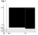
- the fire condition and the non-fire condition are illustrated in a coordinate system.
- the ordinate of the coordinate system shows the current given within the crash signal generation circuit and the abscissa shows the duration for which the respective current is given within the crash signal generation circuit.
- the dark plains illustrate an area in which the fire condition is fulfilled and the bright plains illustrate an area in which the non-fire condition is fulfilled.
- a crash detection circuit for the detection of a crash of a vehicle.
- the crash detection circuit comprises a crash signal generation circuit which is adapted to generate a crash signal; and a crash signal evaluation circuit coupled with the crash signal generation circuit via a transformer, wherein the transformer comprises a first inductor forming a part of the crash signal generation circuit and a second inductor forming a part of the crash signal evaluation circuit, the second inductor being galvanically isolated from the first inductor.
- the crash signal evaluation circuit is adapted to evaluate the signal generated by the crash signal generation circuit and comprises a first comparator comprising an output and an inverting and a non-inverting input, each input being electrically coupled to a terminal of the second inductor of the transformer respectively.
- the crash signal evaluation circuit comprises a window comparator comprising a first input terminal for an input voltage to be evaluated and two second input terminals for reference voltages, wherein the output of the first comparator is electrically connected to the first input terminal of the window comparator.
- the window comparator further comprises an output for a crash signal evaluation signal.
- the reference voltages inputted into the second input terminals define the size of the voltage window of the window comparator.
- the crash detection circuit further comprises a voltage divider circuit comprising at least two resistors connected in series, wherein a terminal of one of the at least two resistors is electrically connected to the non-inverting input of the first comparator.
- a voltage divider circuit comprising at least two resistors connected in series, wherein a terminal of one of the at least two resistors is electrically connected to the non-inverting input of the first comparator.
- the use of such a voltage divider circuit together with the first comparator and the window comparator allows for the crash detection circuit to output a signal indicating the detection of a crash when the fire condition is met and to output a signal indicating that a crash was not detected when the non-fire condition is met.
- the values of the at least two resistors are chosen such that the crash detection circuit is adapted to continuously control whether the fire condition or the non-fire condition is met.
- the voltage window of the window comparator is defined by constant reference voltages provided by the voltage divider circuit which allows for an efficient design of the crash detection circuit, as the resistors of the voltage divider circuit are used for a plurality of purposes.
- the voltage divider circuit comprises four series connected resistors, wherein the non-inverting input of the first comparator is electrically connected to a terminal of one of the four resistors, wherein the aforementioned terminal electrically connects the second and the third resistor, counted from one of the outermost resistors of the four series connected resistors.
- the threshold voltages or reference voltages defining the voltage window of the window comparator can be chosen in a more precise manner, as more resistors allow for a division of the voltage supplied to the voltage divider circuit into smaller fractions.
- all resistors of the voltage divider circuit have the same value, dividing the voltage supplied to the voltage divider circuit into equal fractions.
- a potential is supplied to the non-inverting input of the first comparator which is equal to half the voltage supplied to the voltage divider circuit.
- the voltage divider circuit comprises four series connected resistors, wherein the non-inverting input of the first comparator is electrically connected to a terminal of one of the four resistors, wherein the aforementioned terminal electrically connects the first and the second resistor or the third and the fourth resistor, counted from one of the outermost resistors of the four series connected resistors.
- one of the two second input terminals of the window comparator is electrically connected to a terminal of the first resistor, wherein the aforementioned terminal electrically connects the first resistor with the second resistor.
- the other one of the two second input terminals of the window comparator is electrically connected to a terminal of the third resistor, wherein the aforementioned terminal electrically connects the third resistor with the fourth resistor.
- the size of the voltage window of the window comparator is defined by the voltage which drops at the series connection of the second and third resistor.
- the terminal of the first resistor which is not connected to the second resistor is electrically connected to a first voltage potential and wherein the terminal of the fourth resistor which is not connected to the third resistor is electrically connected to a second voltage potential, the first voltage potential being greater than the second voltage potential.
- the terminal of the first resistor which is not connected to the second resistor is electrically connected to a first voltage potential which is equal to 5V.
- the terminal of the fourth resistor which is not connected to the third resistor is electrically connected to a second voltage potential which is equal to the GND potential.
- the second input terminal of the window comparator that is electrically connected to a terminal of the first resistor is an inverting input of the window comparator and wherein the second input terminal of the window comparator that is electrically connected to a terminal of the third resistor is a non-inverting input of the window comparator.
- the potential supplied to the inverting input of the window comparator denotes an upper boarder of the voltage window of the window comparator.
- the potential supplied to the non-inverting input of the window comparator denotes a lower boarder of the voltage window of the window comparator.
- the voltage at the output of the window comparator depends on the result of a comparison of the output voltage at the output of the first comparator with the voltages supplied to the second input terminals of the second inductor, thus to the upper and lower boarder of the voltage window of the window comparator.
- the window comparator compares the output voltage of the first comparator to the reference voltages inputted into the second input terminals of the window comparator.
- the window comparator outputs a low signal, when the output voltage of the first comparator falls into the voltage window of the window comparator.
- the window comparator outputs a high signal when the output voltage of the first comparator falls out of the voltage window of the window comparator.
- the first comparator is an operational amplifier.
- Operational amplifiers have a low voltage offset and are very precise amplifiers.
- the crash detection circuit further comprises a parallel circuit of a resistor and a capacitor, wherein the output of the first comparator is electrically connected to a first terminal of the parallel circuit and wherein a second terminal of the parallel circuit is electrically connected to the inverting input of the first comparator.
- a parallel circuit in the feedback connection of the first comparator adapts and adjusts the time constant of the first comparator, allowing for the aforementioned implementation of the fire condition and the non-fire condition.
- a resistor is connected in series to the first inductor.
- the resistance of the input clamps of the crash signal generation circuit is adapted.
- a further resistor is arranged within the electrical connection between the inverting input of the first comparator and the terminal of the second inductor. Also this resistor is used to precisely adjust the time constant of the first comparator.
- the transformer is a current transformer.
- the crash detection circuit is advantageously usable with existing current generation sources present in vehicles, wherein such current generation sources are adapted to generate a current in case of a crash.
- the current generation source for example can be a current source that is the emulation of a crash signal according to a standard of a vehicle manufacturer.
- the transformer is a voltage transformer.
- the crash detection circuit is advantageously usable with existing voltage sources present in vehicles, wherein such voltage sources are adapted to generate a voltage in case of a crash.
- the voltage source for example can be a voltage source that is the emulation of a crash signal according to a standard of a vehicle manufacturer.
- At least one resistor is connected in series and/or in parallel to the first inductor.
- the transformer is a voltage transformer.
- the at least one resistor is used to limit the voltage supplied to the first inductor of the transformer.
- a vehicle including a crash detection circuit according to the invention is provided.
- the crash detection of the vehicle is improved for the aforementioned reasons.
- first and second are used to describe various elements, these elements should not be limited by these terms. These terms are only used to distinguish one element from another element. For example, a first element may be named a second element and, similarly, a second element may be named a first element, without departing from the scope of the present invention.
- the term “substantially,” “about,” and similar terms are used as terms of approximation and not as terms of degree, and are intended to account for the inherent deviations in measured or calculated values that would be recognized by those of ordinary skill in the art. Further, if the term “substantially” is used in combination with a feature that could be expressed using a numeric value, the term “substantially” denotes a range of +/- 5% of the value centered on the value.
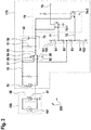
- FIG. 2 illustrates a first embodiment of a crash detection circuit 200.
- the crash detection circuit 200 is implemented into a vehicle (not shown in figure 2 ) and adapted to detect a crash of this aforementioned vehicle.
- the crash detection circuit 200 substantially comprises two sub-circuits which are galvanically isolated from each other.
- the first sub-circuit is a crash signal generation circuit 180 which is adapted to generate a crash signal.
- This crash signal can be represented by a current or a voltage which can be generated by a current source or a voltage source respectively.
- the second sub-circuit is a crash signal evaluation circuit 170 which is adapted to evaluate the signal generated by the crash signal generation circuit 180.
- the crash detection circuit 200 comprises a transformer 90 which comprises a first inductor 91 forming a part of the crash signal generation circuit 180 and a second inductor 92 which forms a part of the crash signal evaluation circuit 170.
- the first and the second inductor 91, 92 are galvanically isolated and separated from each other.
- the crash detection circuit 200 further comprises a first comparator 80 which comprises an output 85, an inverting input 81 and a non-inverting input 82, each input 81, 82 being electrically coupled to a terminal of the second inductor 92 of the transformer 90 respectively.
- the inverting input 81 of the first comparator 80 is electrically connected to a first terminal of the second inductor 92 and the non-inverting input 82 is electrically connected to a second terminal of the second inductor 92.
- the crash detection circuit 200 comprises a window comparator 70.
- the window comparator 70 comprises a first input terminal 75 for an input voltage to be evaluated and two second input terminals 71, 72 for reference voltages U ref1 , U ref2 wherein the reference voltages U ref1 , U ref2 define the size of the voltage window of the window comparator 70 and are supplied to the two second input terminals 71, 72.
- the first reference voltage U ref1 is supplied to the first of the two second input terminals 71 and defines an upper boarder of the voltage window of the window comparator 70, wherein the second reference voltage U ref2 is supplied to the second of the two second input terminals 72 and defines a lower boarder of the voltage window of the window comparator 70.
- the reference voltages U ref1 , U ref2 are constant and supplied by a further component of the crash signal evaluation circuit 170 which in figure 2 is not shown.
- the mean value U mean of the reference voltages U ref1 , U ref2 is supplied to the non-inverting input 82 of the first comparator 80, wherein the mean value U mean is equal to (U ref1 + U ref2 )/2.
- the mean value U mean is supplied to the non-inverting input 82 of the first comparator 80 via the aforementioned further component. However, it can also be provided to the non-inverting input 82 via another component.
- the output 85 of the first comparator 80 is electrically connected to the first input terminal 75 of the window comparator 70.
- the signal outputted by the output 85 of the first comparator 80 is compared to the reference voltages U ref1 , U ref2 .
- the reference voltages are chosen such that the crash signal evaluation circuit 170 continuously evaluates whether the fire condition or the non-fire condition as shown in the coordinate system of figure 1 are met.
- the window comparator 70 outputs a corresponding signal via its output 79 when the fire condition is met and a crash has been successfully detected.
- a second embodiment of a crash detection circuit 200 with a current transformer 90 is shown.
- the crash detection circuit 200 comprises a crash signal generation circuit 180 and a crash signal evaluation circuit 170.
- the crash signal generation circuit 180 comprises a current source 181 for the generation of a current corresponding to a crash signal.
- the current source 181 is shown as a single component. However, the current within the crash signal generation circuit 180 can be generated via a plurality of components which in figure 3 are not shown.
- the crash detection circuit 200 comprises a transformer 90, which in this second embodiment is realized as a current transformer 90.
- the first comparator 80 is realized as an operational amplifier, wherein the inverting input 81 of the operational amplifier is electrically connected to a first terminal of the second inductor 92 and wherein the non-inverting input 82 of the operational amplifier is electrically connected to a second terminal of the second inductor 92.
- a first power supply terminal 84 of the operational amplifier is electrically connected to a potential of 5V, wherein the other power supply terminal 86 of the operational amplifier is electrically connected to a GND potential.
- the crash signal evaluation circuit 170 further comprises a voltage divider circuit 160 that comprises four series connected resistors 61, 62, 63, 64.
- the voltage divider circuit 160 comprises a first terminal 161 electrically connected to a first resistor 61.
- This first resistor 61 is electrically connected to a second resistor 62, which is electrically connected to a third resistor 63.
- This third resistor 63 is electrically connected to a fourth resistor 64 which is electrically connected to a second terminal 162 of the voltage divider circuit 160.
- the first, second, third and fourth resistor 61, 62, 63, 64 have an identical value.
- the values of the first, second, third and fourth resistor 61, 62, 63, 64 may differ from one another.
- the voltage divider circuit 160 can comprise three or more than four resistors.
- the first terminal 161 of the voltage divider circuit 160 is electrically connected to a potential of exemplarily 5V, wherein the second terminal 162 of the voltage divider circuit 160 is exemplarily electrically connected to the GND potential.
- the first and second terminal 161, 162 of the voltage divider circuit 160 can also be connected to other potentials.
- the non-inverting input 82 of the first comparator 80 is electrically connected to a terminal of one of the four resistors 61, 62, 63, 64 wherein the aforementioned terminal electrically connects the second and the third resistor 62, 63, counted from one of the outermost resistors 61, 64 of the four series connected resistors 61, 62, 63, 64.
- the non-inverting input 82 of the first comparator 80 is directly electrically connected to the terminals of the second and third resistor 62, 63, which in this second embodiment exemplarily have a potential of exemplarily 2.5V.
- one of the two second input terminals 71 of the window comparator 70 is electrically connected to a terminal of the first resistor 61, wherein the aforementioned terminal electrically connects the first resistor 61 with the second resistor 62.
- the first of the two second input terminals 71 of the window comparator 70 which exemplarily is an inverting input terminal of the window comparator 70, is directly electrically connected to the terminals of the first and second resistor 61, 62.
- the second of the two second input terminals 72 of the window comparator 70 which exemplarily is a non-inverting input terminal of the window comparator 70, is directly electrically connected to the terminal of the third resistor 63 which is directly connected to the fourth resistor 64.
- the second of the two second input terminals 72 of the window comparator 70 which exemplarily is a non-inverting input terminal of the window comparator 70, is directly electrically connected to the terminals of the third and fourth resistor 63, 64.
- the voltage drop across the second and third resistor 62, 63 determines the size of the voltage window of the window comparator 70 which in this second embodiment exemplarily has a span of 2.5V.
- the output 85 of the first comparator 80 is electrically connected to the first input terminal 75 of the window comparator 70.
- the window comparator 70 comprises two further comparators 70-1, 70-2 which also can be operational amplifiers. However, also other and further comparators can come to use, the other/further comparators together forming a window comparator 70.
- the crash detection circuit 200 further comprises a parallel circuit 50 of a resistor 51 and a capacitor 52, wherein the output 85 of the first comparator 80 is electrically connected to a first terminal of the parallel circuit 50 and wherein a second terminal of the parallel circuit 50 is electrically connected to the inverting input 81 of the first comparator 80.
- the parallel circuit 50 is arranged within the feedback circuit of the first comparator 80.
- a further resistor 55 is arranged within the electrical connection between the inverting input 81 of the first comparator 80 and the terminal of the second inductor 92. Via the parallel circuit 50 and the further resistor 55, the time constant of the operational amplifier is adjusted according to the non-fire condition and the fire condition as illustrated in figure 1 .
- the crash signal evaluation circuit 170 outputs an output signal which is according to the evaluation.
- FIG. 4 illustrates a third embodiment of a crash detection circuit 200 with a voltage transformer 90.
- the crash detection circuit 200 shown in figure 4 is substantially identical to the crash detection circuit 200 as shown in figure 3 .
- a voltage transformer 90 comes to use, the crash signal generation circuit 180 needs to be adapted.
- two resistors 58 are connected in series to the first inductor 91 of the voltage transformer 90, wherein a further resistor 59 is connected in parallel to the first inductor 91 of the voltage transformer 90.
- FIG 5 a simulation is illustrated using the second embodiment of a crash detection circuit 200.
- two diagrams are shown in figure 5 .
- the upper diagram shows different crash pulses which are given as an input for the crash detection circuit 200 within the crash signal generation circuit 180.
- the lower diagram shows the evaluation of the crash detection circuit 200 at its output 79. It can be seen from figure 5 that the crash pulses denoted A have a duration which is too short to fulfill the fire condition (see figure 1 ), while the crash pulses denoted B have a current amplitude that is too low to fulfill the fire condition (see figure 1 ), as no output signal is generated and outputted at the output 79 of the crash detection circuit 200.
Landscapes
- Physics & Mathematics (AREA)
- General Physics & Mathematics (AREA)
- Engineering & Computer Science (AREA)
- Mechanical Engineering (AREA)
- Measurement Of Current Or Voltage (AREA)
Claims (15)
- Eine Unfalldetektionsschaltung (200) zur Detektion eines Fahrzeugunfalls, aufweisend:eine Unfallsignalerzeugungsschaltung (180), die angepasst ist, um ein Unfallsignal zu erzeugen; undeine Unfallsignalauswertungsschaltung (170), die über einen Transformator (90) mit der Unfallsignalerzeugungsschaltung (180) gekoppelt ist, wobei der Transformator (90) eine erste Induktivität (91), die einen Teil der Unfallsignalerzeugungsschaltung (180) ausbildet, und eine zweite Induktivität (92), die einen Teil der Unfallsignalauswertungsschaltung (170) ausbildet, aufweist, wobei die zweite Induktivität (92) von der ersten Induktivität (91) galvanisch getrennt ist,wobei die Unfallsignalauswertungsschaltung (170) angepasst ist, um das Signal, das von der Unfallsignalerzeugungsschaltung (180) erzeugt wird, auszuwerten, und ferner aufweist: einen ersten Komparator (80), der einen Ausgang (85) und einen invertierenden und einen nicht-invertierenden Eingang (81, 82) aufweist, wobei jeder Eingang (81, 82) jeweils mit einem Anschluss der zweiten Induktivität (92) des Transformators (90) elektrisch gekoppelt ist, und einen Fensterkomparator (70), der einen ersten Eingangsanschluss (75) für eine Eingangsspannung, die ausgewertet werden soll, und zwei zweite Eingangsanschlüsse (71, 72) für Referenzspannungen aufweist, wobei der Ausgang des ersten Komparators (80) mit dem ersten Eingangsanschluss (75) des Fensterkomparators (70) elektrisch verbunden ist.
- Die Unfalldetektionsschaltung (200) nach Anspruch 1, ferner aufweisend eine Spannungsteilerschaltung (160), die zumindest zwei in Reihe geschaltete Widerstände (61, 62) aufweist, wobei ein Anschluss eines der zumindest zwei Widerstände (61, 62) mit dem nicht-invertierenden Eingang (82) des ersten Komparators (80) elektrisch verbunden ist.
- Die Unfalldetektionsschaltung (200) nach Anspruch 2, wobei ein weiterer Anschluss eines der zumindest zwei Widerstände (61, 62) mit einem der zwei zweiten Eingangsanschlüsse (71, 72) des Fensterkomparators (70) elektrisch verbunden ist, und wobei ein weiterer Anschluss eines der zumindest zwei Widerstände (61, 62) mit dem anderen der zwei zweiten Eingangsanschlüsse (71, 72) des Fensterkomparators (70) elektrisch verbunden ist.
- Die Unfalldetektionsschaltung (200) nach Anspruch 2 oder 3, wobei die Spannungsteilerschaltung (160) vier in Reihe geschaltete Widerstände (61, 62, 63, 64) aufweist, wobei der nicht-invertierende Eingang (82) des ersten Komparators (80) mit einem Anschluss eines der vier Widerstände (62, 63) elektrisch verbunden ist, wobei der vorgenannte Anschluss den zweiten und den dritten Widerstand (62, 63) - gezählt von einem der äußersten Widerstände (61, 64) der vier in Reihe geschalteten Widerstände (61, 62, 63, 64) - elektrisch verbindet.
- Die Unfalldetektionsschaltung (200) nach Anspruch 4, wobei einer der zwei zweiten Eingangsanschlüsse (71) des Fensterkomparators (70) mit einem Anschluss des ersten Widerstands (61) elektrisch verbunden ist, wobei der vorgenannte Anschluss den ersten Widerstand (61) mit dem zweiten Widerstand (62) elektrisch verbindet.
- Die Unfalldetektionsschaltung (200) nach Anspruch 5, wobei der andere der zwei zweiten Eingangsanschlüsse (72) des Fensterkomparators (70) mit einem Anschluss des dritten Widerstands (63) elektrisch verbunden ist, wobei der vorgenannte Anschluss den dritten Widerstand (63) mit dem vierten Widerstand (64) elektrisch verbindet.
- Die Unfalldetektionsschaltung (200) nach einem der Ansprüche 4 bis 6, wobei der Anschluss des ersten Widerstands (61), der nicht mit dem zweiten Widerstand (62) verbunden ist, mit einem ersten Spannungspotential elektrisch verbunden ist, und wobei der Anschluss des vierten Widerstands (64), der nicht mit dem dritten Widerstand (63) verbunden ist, mit einem zweiten Spannungspotential elektrisch verbunden ist, wobei das erste Spannungspotential größer als das zweite Spannungspotential ist.
- Die Unfalldetektionsschaltung (200) nach Anspruch 6 und 7, wobei der zweite Eingangsanschluss (71) des Fensterkomparators (70), der mit einem Anschluss des ersten Widerstands (61) elektrisch verbunden ist, ein invertierender Eingang des Fensterkomparators (70) ist, und wobei der zweite Eingangsanschluss (72) des Fensterkomparators (70), der mit einem Anschluss des dritten Widerstands (63) elektrisch verbunden ist, ein nichtinvertierender Eingang des Fensterkomparators (70) ist.
- Die Unfalldetektionsschaltung (200) nach einem der vorhergehenden Ansprüche, wobei der erste Komparator (80) ein Operationsverstärker ist.
- Die Unfalldetektionsschaltung (200) nach einem der vorhergehenden Ansprüche, ferner aufweisend eine Parallelschaltung (50) eines Widerstands (51) und eines Kondensators (52), wobei der Ausgang (85) des ersten Komparators (80) mit einem ersten Anschluss der Parallelschaltung (50) elektrisch verbunden ist, und wobei ein zweiter Anschluss der Parallelschaltung (50) mit dem invertierenden Eingang (81) des ersten Komparators (80) elektrisch verbunden ist.
- Die Unfalldetektionsschaltung (200) nach einem der vorhergehenden Ansprüche, wobei ein weiterer Widerstand (55) in der elektrischen Verbindung zwischen dem invertierenden Eingang (81) des ersten Komparators (80) und dem Anschluss der zweiten Induktivität (92) angeordnet ist.
- Die Unfalldetektionsschaltung (200) nach einem der vorhergehenden Ansprüche, wobei der Transformator (90) ein Stromwandler ist.
- Die Unfalldetektionsschaltung (200) nach einem der Ansprüche 1 bis 11, wobei der Transformator (90) ein Spannungswandler ist.
- Die Unfalldetektionsschaltung (200) nach Anspruch 13, wobei zumindest ein Widerstand (58) mit der ersten Induktivität (91) in Reihe und/oder parallel geschaltet ist.
- Ein Fahrzeug, aufweisend eine Unfalldetektionsschaltung (200) nach einem der vorhergehenden Ansprüche.
Priority Applications (2)
| Application Number | Priority Date | Filing Date | Title |
|---|---|---|---|
| EP16195835.0A EP3315918B1 (de) | 2016-10-26 | 2016-10-26 | Unfalldetektionsschaltung zur detektion eines fahrzeugunfalls |
| US15/420,914 US10414350B2 (en) | 2016-10-26 | 2017-01-31 | Crash detection circuit for the detection of a crash of a vehicle |
Applications Claiming Priority (1)
| Application Number | Priority Date | Filing Date | Title |
|---|---|---|---|
| EP16195835.0A EP3315918B1 (de) | 2016-10-26 | 2016-10-26 | Unfalldetektionsschaltung zur detektion eines fahrzeugunfalls |
Publications (2)
| Publication Number | Publication Date |
|---|---|
| EP3315918A1 EP3315918A1 (de) | 2018-05-02 |
| EP3315918B1 true EP3315918B1 (de) | 2018-08-22 |
Family
ID=57354096
Family Applications (1)
| Application Number | Title | Priority Date | Filing Date |
|---|---|---|---|
| EP16195835.0A Active EP3315918B1 (de) | 2016-10-26 | 2016-10-26 | Unfalldetektionsschaltung zur detektion eines fahrzeugunfalls |
Country Status (2)
| Country | Link |
|---|---|
| US (1) | US10414350B2 (de) |
| EP (1) | EP3315918B1 (de) |
Families Citing this family (4)
| Publication number | Priority date | Publication date | Assignee | Title |
|---|---|---|---|---|
| CN113815422A (zh) * | 2020-06-18 | 2021-12-21 | 宁德时代新能源科技股份有限公司 | 碰撞检测电路、电池管理系统及车辆 |
| CN114265119A (zh) * | 2021-12-22 | 2022-04-01 | 浙江清华柔性电子技术研究院 | 碰撞检测系统和方法 |
| KR20240175549A (ko) * | 2023-06-13 | 2024-12-20 | 삼성에스디아이 주식회사 | 충돌 스위치 회로 및 이를 포함하는 충돌 감지 시스템 |
| KR20250060556A (ko) * | 2023-10-26 | 2025-05-07 | 삼성에스디아이 주식회사 | 배터리 관리 장치용 충격 감지 회로 |
Citations (1)
| Publication number | Priority date | Publication date | Assignee | Title |
|---|---|---|---|---|
| US20110075158A1 (en) * | 2009-09-30 | 2011-03-31 | Delphi Technologies, Inc. | Optical crash sensor |
Family Cites Families (13)
| Publication number | Priority date | Publication date | Assignee | Title |
|---|---|---|---|---|
| JPH0753499B2 (ja) | 1988-05-12 | 1995-06-07 | 三菱電機株式会社 | エアバッグ装置の故障検出装置 |
| JP3163425B2 (ja) * | 1993-03-31 | 2001-05-08 | 日本信号株式会社 | モータの回転有無判定回路及びこれを用いたモータの回転停止確認装置 |
| EP0723161B1 (de) * | 1994-08-08 | 2001-11-14 | The Nippon Signal Co. Ltd. | Fehlerüberwachungsanordnung für brückenschaltung |
| EP0732593B1 (de) * | 1994-09-30 | 2000-03-01 | The Nippon Signal Co. Ltd. | Anordnung zur bestätigung des anhaltens eines motor |
| US6015484A (en) * | 1997-11-26 | 2000-01-18 | Gamry Instruments, Inc. | Detection of pitting corrosion |
| JP3578959B2 (ja) * | 2000-02-24 | 2004-10-20 | 松下電器産業株式会社 | テーブルタップおよびテーブルタップを用いた監視システム |
| GB0015349D0 (en) * | 2000-06-23 | 2000-08-16 | Atherton Eric | Corrosion monitoring |
| EP1733214A2 (de) * | 2004-04-09 | 2006-12-20 | Southwest Research Institute | Verbessertes verfahren zur messung vonlokalisierter korrosionsgeschwindigkeit mit einemmehrfachelektrodenarray-sensor |
| US9124087B2 (en) * | 2008-08-15 | 2015-09-01 | Technology Research Corporation | Arc suppression circuit |
| CN102472773A (zh) * | 2010-04-23 | 2012-05-23 | 松下电器产业株式会社 | 检测装置以及检测系统 |
| JP2014052296A (ja) * | 2011-09-09 | 2014-03-20 | Gs Yuasa Corp | 監視装置 |
| JP2013238472A (ja) | 2012-05-15 | 2013-11-28 | Renesas Electronics Corp | 半導体装置および電圧測定装置 |
| KR20150118730A (ko) | 2014-04-15 | 2015-10-23 | 엘에스산전 주식회사 | 인버터 고장검출회로 |
-
2016
- 2016-10-26 EP EP16195835.0A patent/EP3315918B1/de active Active
-
2017
- 2017-01-31 US US15/420,914 patent/US10414350B2/en active Active
Patent Citations (1)
| Publication number | Priority date | Publication date | Assignee | Title |
|---|---|---|---|---|
| US20110075158A1 (en) * | 2009-09-30 | 2011-03-31 | Delphi Technologies, Inc. | Optical crash sensor |
Also Published As
| Publication number | Publication date |
|---|---|
| US20180111572A1 (en) | 2018-04-26 |
| US10414350B2 (en) | 2019-09-17 |
| EP3315918A1 (de) | 2018-05-02 |
Similar Documents
| Publication | Publication Date | Title |
|---|---|---|
| EP3315918A1 (de) | Unfalldetektionsschaltung zur detektion eines fahrzeugunfalls | |
| US10429430B2 (en) | Method for operating a capacitive sensor arrangement of a motor vehicle | |
| CN108195465B (zh) | 一种光信号检测装置及方法 | |
| US20090212826A1 (en) | Hysteresis comparator | |
| EP2916111B1 (de) | Wärmedurchflussmesser | |
| US9739822B2 (en) | Input circuit | |
| KR101671087B1 (ko) | 시퀀서 아날로그 출력 유닛 | |
| US10514307B2 (en) | Fault detection apparatus | |
| CN106936175B (zh) | 充放电控制电路及电池装置 | |
| TWI512310B (zh) | 三相電源異常偵測裝置 | |
| US8519744B2 (en) | Method of utilizing dual comparators to facilitate a precision signal rectification and timing system without signal feedback | |
| JP2015197820A (ja) | 電子機器および画像形成装置 | |
| EP2362711B1 (de) | Fehlererkennung von LEDs | |
| CN107107850B (zh) | 用于车辆的人员保护装置的至少一个点火电路的监测装置和用于运行监测装置的方法 | |
| WO2014087854A1 (ja) | 電子制御装置 | |
| JP5157972B2 (ja) | 地絡検出装置 | |
| US20190235006A1 (en) | Wiring line abnormality detecting device | |
| KR20150145683A (ko) | 조명제어용 데이터신호 수신회로 | |
| JP5950084B2 (ja) | 状態監視装置 | |
| JPH05291899A (ja) | ヒステリシスコンパレータ回路 | |
| JP2006349466A (ja) | 温度検出装置 | |
| CN117459033B (zh) | 滞回比较电路、电压检测装置及过压欠压检测装置 | |
| EP4170365B1 (de) | Drahtbruch detektion für analoge differenzeingänge unter verwendung einer wechselstromvorspannung | |
| JP6309332B2 (ja) | 可変抵抗器の抵抗検知信号生成回路 | |
| KR101409086B1 (ko) | 입력 정전압 상태 판단 회로 |
Legal Events
| Date | Code | Title | Description |
|---|---|---|---|
| PUAI | Public reference made under article 153(3) epc to a published international application that has entered the european phase |
Free format text: ORIGINAL CODE: 0009012 |
|
| STAA | Information on the status of an ep patent application or granted ep patent |
Free format text: STATUS: REQUEST FOR EXAMINATION WAS MADE |
|
| 17P | Request for examination filed |
Effective date: 20170919 |
|
| AK | Designated contracting states |
Kind code of ref document: A1 Designated state(s): AL AT BE BG CH CY CZ DE DK EE ES FI FR GB GR HR HU IE IS IT LI LT LU LV MC MK MT NL NO PL PT RO RS SE SI SK SM TR |
|
| AX | Request for extension of the european patent |
Extension state: BA ME |
|
| GRAP | Despatch of communication of intention to grant a patent |
Free format text: ORIGINAL CODE: EPIDOSNIGR1 |
|
| STAA | Information on the status of an ep patent application or granted ep patent |
Free format text: STATUS: GRANT OF PATENT IS INTENDED |
|
| INTG | Intention to grant announced |
Effective date: 20180530 |
|
| GRAS | Grant fee paid |
Free format text: ORIGINAL CODE: EPIDOSNIGR3 |
|
| GRAA | (expected) grant |
Free format text: ORIGINAL CODE: 0009210 |
|
| STAA | Information on the status of an ep patent application or granted ep patent |
Free format text: STATUS: THE PATENT HAS BEEN GRANTED |
|
| AK | Designated contracting states |
Kind code of ref document: B1 Designated state(s): AL AT BE BG CH CY CZ DE DK EE ES FI FR GB GR HR HU IE IS IT LI LT LU LV MC MK MT NL NO PL PT RO RS SE SI SK SM TR |
|
| REG | Reference to a national code |
Ref country code: GB Ref legal event code: FG4D |
|
| REG | Reference to a national code |
Ref country code: CH Ref legal event code: EP |
|
| REG | Reference to a national code |
Ref country code: AT Ref legal event code: REF Ref document number: 1033032 Country of ref document: AT Kind code of ref document: T Effective date: 20180915 |
|
| REG | Reference to a national code |
Ref country code: IE Ref legal event code: FG4D |
|
| REG | Reference to a national code |
Ref country code: DE Ref legal event code: R096 Ref document number: 602016004969 Country of ref document: DE |
|
| REG | Reference to a national code |
Ref country code: FR Ref legal event code: PLFP Year of fee payment: 3 |
|
| REG | Reference to a national code |
Ref country code: NL Ref legal event code: MP Effective date: 20180822 |
|
| REG | Reference to a national code |
Ref country code: LT Ref legal event code: MG4D |
|
| PG25 | Lapsed in a contracting state [announced via postgrant information from national office to epo] |
Ref country code: LT Free format text: LAPSE BECAUSE OF FAILURE TO SUBMIT A TRANSLATION OF THE DESCRIPTION OR TO PAY THE FEE WITHIN THE PRESCRIBED TIME-LIMIT Effective date: 20180822 Ref country code: FI Free format text: LAPSE BECAUSE OF FAILURE TO SUBMIT A TRANSLATION OF THE DESCRIPTION OR TO PAY THE FEE WITHIN THE PRESCRIBED TIME-LIMIT Effective date: 20180822 Ref country code: NL Free format text: LAPSE BECAUSE OF FAILURE TO SUBMIT A TRANSLATION OF THE DESCRIPTION OR TO PAY THE FEE WITHIN THE PRESCRIBED TIME-LIMIT Effective date: 20180822 Ref country code: BG Free format text: LAPSE BECAUSE OF FAILURE TO SUBMIT A TRANSLATION OF THE DESCRIPTION OR TO PAY THE FEE WITHIN THE PRESCRIBED TIME-LIMIT Effective date: 20181122 Ref country code: SE Free format text: LAPSE BECAUSE OF FAILURE TO SUBMIT A TRANSLATION OF THE DESCRIPTION OR TO PAY THE FEE WITHIN THE PRESCRIBED TIME-LIMIT Effective date: 20180822 Ref country code: RS Free format text: LAPSE BECAUSE OF FAILURE TO SUBMIT A TRANSLATION OF THE DESCRIPTION OR TO PAY THE FEE WITHIN THE PRESCRIBED TIME-LIMIT Effective date: 20180822 Ref country code: IS Free format text: LAPSE BECAUSE OF FAILURE TO SUBMIT A TRANSLATION OF THE DESCRIPTION OR TO PAY THE FEE WITHIN THE PRESCRIBED TIME-LIMIT Effective date: 20181222 Ref country code: GR Free format text: LAPSE BECAUSE OF FAILURE TO SUBMIT A TRANSLATION OF THE DESCRIPTION OR TO PAY THE FEE WITHIN THE PRESCRIBED TIME-LIMIT Effective date: 20181123 Ref country code: NO Free format text: LAPSE BECAUSE OF FAILURE TO SUBMIT A TRANSLATION OF THE DESCRIPTION OR TO PAY THE FEE WITHIN THE PRESCRIBED TIME-LIMIT Effective date: 20181122 |
|
| PG25 | Lapsed in a contracting state [announced via postgrant information from national office to epo] |
Ref country code: HR Free format text: LAPSE BECAUSE OF FAILURE TO SUBMIT A TRANSLATION OF THE DESCRIPTION OR TO PAY THE FEE WITHIN THE PRESCRIBED TIME-LIMIT Effective date: 20180822 Ref country code: LV Free format text: LAPSE BECAUSE OF FAILURE TO SUBMIT A TRANSLATION OF THE DESCRIPTION OR TO PAY THE FEE WITHIN THE PRESCRIBED TIME-LIMIT Effective date: 20180822 Ref country code: AL Free format text: LAPSE BECAUSE OF FAILURE TO SUBMIT A TRANSLATION OF THE DESCRIPTION OR TO PAY THE FEE WITHIN THE PRESCRIBED TIME-LIMIT Effective date: 20180822 |
|
| PG25 | Lapsed in a contracting state [announced via postgrant information from national office to epo] |
Ref country code: RO Free format text: LAPSE BECAUSE OF FAILURE TO SUBMIT A TRANSLATION OF THE DESCRIPTION OR TO PAY THE FEE WITHIN THE PRESCRIBED TIME-LIMIT Effective date: 20180822 Ref country code: CZ Free format text: LAPSE BECAUSE OF FAILURE TO SUBMIT A TRANSLATION OF THE DESCRIPTION OR TO PAY THE FEE WITHIN THE PRESCRIBED TIME-LIMIT Effective date: 20180822 Ref country code: IT Free format text: LAPSE BECAUSE OF FAILURE TO SUBMIT A TRANSLATION OF THE DESCRIPTION OR TO PAY THE FEE WITHIN THE PRESCRIBED TIME-LIMIT Effective date: 20180822 Ref country code: EE Free format text: LAPSE BECAUSE OF FAILURE TO SUBMIT A TRANSLATION OF THE DESCRIPTION OR TO PAY THE FEE WITHIN THE PRESCRIBED TIME-LIMIT Effective date: 20180822 Ref country code: ES Free format text: LAPSE BECAUSE OF FAILURE TO SUBMIT A TRANSLATION OF THE DESCRIPTION OR TO PAY THE FEE WITHIN THE PRESCRIBED TIME-LIMIT Effective date: 20180822 Ref country code: PL Free format text: LAPSE BECAUSE OF FAILURE TO SUBMIT A TRANSLATION OF THE DESCRIPTION OR TO PAY THE FEE WITHIN THE PRESCRIBED TIME-LIMIT Effective date: 20180822 |
|
| REG | Reference to a national code |
Ref country code: DE Ref legal event code: R097 Ref document number: 602016004969 Country of ref document: DE |
|
| PG25 | Lapsed in a contracting state [announced via postgrant information from national office to epo] |
Ref country code: SK Free format text: LAPSE BECAUSE OF FAILURE TO SUBMIT A TRANSLATION OF THE DESCRIPTION OR TO PAY THE FEE WITHIN THE PRESCRIBED TIME-LIMIT Effective date: 20180822 Ref country code: DK Free format text: LAPSE BECAUSE OF FAILURE TO SUBMIT A TRANSLATION OF THE DESCRIPTION OR TO PAY THE FEE WITHIN THE PRESCRIBED TIME-LIMIT Effective date: 20180822 Ref country code: SM Free format text: LAPSE BECAUSE OF FAILURE TO SUBMIT A TRANSLATION OF THE DESCRIPTION OR TO PAY THE FEE WITHIN THE PRESCRIBED TIME-LIMIT Effective date: 20180822 |
|
| REG | Reference to a national code |
Ref country code: BE Ref legal event code: MM Effective date: 20181031 |
|
| PG25 | Lapsed in a contracting state [announced via postgrant information from national office to epo] |
Ref country code: MC Free format text: LAPSE BECAUSE OF FAILURE TO SUBMIT A TRANSLATION OF THE DESCRIPTION OR TO PAY THE FEE WITHIN THE PRESCRIBED TIME-LIMIT Effective date: 20180822 Ref country code: LU Free format text: LAPSE BECAUSE OF NON-PAYMENT OF DUE FEES Effective date: 20181026 |
|
| PLBE | No opposition filed within time limit |
Free format text: ORIGINAL CODE: 0009261 |
|
| STAA | Information on the status of an ep patent application or granted ep patent |
Free format text: STATUS: NO OPPOSITION FILED WITHIN TIME LIMIT |
|
| REG | Reference to a national code |
Ref country code: IE Ref legal event code: MM4A |
|
| 26N | No opposition filed |
Effective date: 20190523 |
|
| PG25 | Lapsed in a contracting state [announced via postgrant information from national office to epo] |
Ref country code: BE Free format text: LAPSE BECAUSE OF NON-PAYMENT OF DUE FEES Effective date: 20181031 Ref country code: SI Free format text: LAPSE BECAUSE OF FAILURE TO SUBMIT A TRANSLATION OF THE DESCRIPTION OR TO PAY THE FEE WITHIN THE PRESCRIBED TIME-LIMIT Effective date: 20180822 |
|
| PG25 | Lapsed in a contracting state [announced via postgrant information from national office to epo] |
Ref country code: IE Free format text: LAPSE BECAUSE OF NON-PAYMENT OF DUE FEES Effective date: 20181026 |
|
| PG25 | Lapsed in a contracting state [announced via postgrant information from national office to epo] |
Ref country code: MT Free format text: LAPSE BECAUSE OF NON-PAYMENT OF DUE FEES Effective date: 20181026 |
|
| PG25 | Lapsed in a contracting state [announced via postgrant information from national office to epo] |
Ref country code: TR Free format text: LAPSE BECAUSE OF FAILURE TO SUBMIT A TRANSLATION OF THE DESCRIPTION OR TO PAY THE FEE WITHIN THE PRESCRIBED TIME-LIMIT Effective date: 20180822 |
|
| PG25 | Lapsed in a contracting state [announced via postgrant information from national office to epo] |
Ref country code: PT Free format text: LAPSE BECAUSE OF FAILURE TO SUBMIT A TRANSLATION OF THE DESCRIPTION OR TO PAY THE FEE WITHIN THE PRESCRIBED TIME-LIMIT Effective date: 20180822 |
|
| REG | Reference to a national code |
Ref country code: CH Ref legal event code: PL |
|
| PG25 | Lapsed in a contracting state [announced via postgrant information from national office to epo] |
Ref country code: MK Free format text: LAPSE BECAUSE OF NON-PAYMENT OF DUE FEES Effective date: 20180822 Ref country code: HU Free format text: LAPSE BECAUSE OF FAILURE TO SUBMIT A TRANSLATION OF THE DESCRIPTION OR TO PAY THE FEE WITHIN THE PRESCRIBED TIME-LIMIT; INVALID AB INITIO Effective date: 20161026 Ref country code: CY Free format text: LAPSE BECAUSE OF FAILURE TO SUBMIT A TRANSLATION OF THE DESCRIPTION OR TO PAY THE FEE WITHIN THE PRESCRIBED TIME-LIMIT Effective date: 20180822 |
|
| PG25 | Lapsed in a contracting state [announced via postgrant information from national office to epo] |
Ref country code: LI Free format text: LAPSE BECAUSE OF NON-PAYMENT OF DUE FEES Effective date: 20191031 Ref country code: CH Free format text: LAPSE BECAUSE OF NON-PAYMENT OF DUE FEES Effective date: 20191031 |
|
| REG | Reference to a national code |
Ref country code: AT Ref legal event code: UEP Ref document number: 1033032 Country of ref document: AT Kind code of ref document: T Effective date: 20180822 |
|
| P01 | Opt-out of the competence of the unified patent court (upc) registered |
Effective date: 20230528 |
|
| PGFP | Annual fee paid to national office [announced via postgrant information from national office to epo] |
Ref country code: FR Payment date: 20250930 Year of fee payment: 10 |
|
| PGFP | Annual fee paid to national office [announced via postgrant information from national office to epo] |
Ref country code: DE Payment date: 20250930 Year of fee payment: 10 |
|
| PGFP | Annual fee paid to national office [announced via postgrant information from national office to epo] |
Ref country code: GB Payment date: 20251001 Year of fee payment: 10 |
|
| PGFP | Annual fee paid to national office [announced via postgrant information from national office to epo] |
Ref country code: AT Payment date: 20251009 Year of fee payment: 10 |