EP3315933A1 - Capteur magnétostrictif, structure magnétique et son procédé de production, unité d'entraînement motorisé pourvue d'un capteur magnétostrictif, et bicyclette assistée à moteur - Google Patents
Capteur magnétostrictif, structure magnétique et son procédé de production, unité d'entraînement motorisé pourvue d'un capteur magnétostrictif, et bicyclette assistée à moteur Download PDFInfo
- Publication number
- EP3315933A1 EP3315933A1 EP16814456.6A EP16814456A EP3315933A1 EP 3315933 A1 EP3315933 A1 EP 3315933A1 EP 16814456 A EP16814456 A EP 16814456A EP 3315933 A1 EP3315933 A1 EP 3315933A1
- Authority
- EP
- European Patent Office
- Prior art keywords
- magnetostrictive
- lines
- base material
- magnetostrictive lines
- outer peripheral
- Prior art date
- Legal status (The legal status is an assumption and is not a legal conclusion. Google has not performed a legal analysis and makes no representation as to the accuracy of the status listed.)
- Granted
Links
Images


Classifications
-
- G—PHYSICS
- G01—MEASURING; TESTING
- G01L—MEASURING FORCE, STRESS, TORQUE, WORK, MECHANICAL POWER, MECHANICAL EFFICIENCY, OR FLUID PRESSURE
- G01L3/00—Measuring torque, work, mechanical power, or mechanical efficiency, in general
- G01L3/02—Rotary-transmission dynamometers
- G01L3/04—Rotary-transmission dynamometers wherein the torque-transmitting element comprises a torsionally-flexible shaft
- G01L3/10—Rotary-transmission dynamometers wherein the torque-transmitting element comprises a torsionally-flexible shaft involving electric or magnetic means for indicating
- G01L3/101—Rotary-transmission dynamometers wherein the torque-transmitting element comprises a torsionally-flexible shaft involving electric or magnetic means for indicating involving magnetic or electromagnetic means
- G01L3/102—Rotary-transmission dynamometers wherein the torque-transmitting element comprises a torsionally-flexible shaft involving electric or magnetic means for indicating involving magnetic or electromagnetic means involving magnetostrictive means
-
- B—PERFORMING OPERATIONS; TRANSPORTING
- B62—LAND VEHICLES FOR TRAVELLING OTHERWISE THAN ON RAILS
- B62M—RIDER PROPULSION OF WHEELED VEHICLES OR SLEDGES; POWERED PROPULSION OF SLEDGES OR SINGLE-TRACK CYCLES; TRANSMISSIONS SPECIALLY ADAPTED FOR SUCH VEHICLES
- B62M6/00—Rider propulsion of wheeled vehicles with additional source of power, e.g. combustion engine or electric motor
- B62M6/40—Rider propelled cycles with auxiliary electric motor
- B62M6/45—Control or actuating devices therefor
- B62M6/50—Control or actuating devices therefor characterised by detectors or sensors, or arrangement thereof
-
- G—PHYSICS
- G01—MEASURING; TESTING
- G01L—MEASURING FORCE, STRESS, TORQUE, WORK, MECHANICAL POWER, MECHANICAL EFFICIENCY, OR FLUID PRESSURE
- G01L3/00—Measuring torque, work, mechanical power, or mechanical efficiency, in general
- G01L3/02—Rotary-transmission dynamometers
- G01L3/04—Rotary-transmission dynamometers wherein the torque-transmitting element comprises a torsionally-flexible shaft
- G01L3/10—Rotary-transmission dynamometers wherein the torque-transmitting element comprises a torsionally-flexible shaft involving electric or magnetic means for indicating
- G01L3/101—Rotary-transmission dynamometers wherein the torque-transmitting element comprises a torsionally-flexible shaft involving electric or magnetic means for indicating involving magnetic or electromagnetic means
- G01L3/102—Rotary-transmission dynamometers wherein the torque-transmitting element comprises a torsionally-flexible shaft involving electric or magnetic means for indicating involving magnetic or electromagnetic means involving magnetostrictive means
- G01L3/103—Details about the magnetic material used
-
- G—PHYSICS
- G01—MEASURING; TESTING
- G01L—MEASURING FORCE, STRESS, TORQUE, WORK, MECHANICAL POWER, MECHANICAL EFFICIENCY, OR FLUID PRESSURE
- G01L3/00—Measuring torque, work, mechanical power, or mechanical efficiency, in general
- G01L3/02—Rotary-transmission dynamometers
- G01L3/04—Rotary-transmission dynamometers wherein the torque-transmitting element comprises a torsionally-flexible shaft
- G01L3/10—Rotary-transmission dynamometers wherein the torque-transmitting element comprises a torsionally-flexible shaft involving electric or magnetic means for indicating
- G01L3/101—Rotary-transmission dynamometers wherein the torque-transmitting element comprises a torsionally-flexible shaft involving electric or magnetic means for indicating involving magnetic or electromagnetic means
- G01L3/105—Rotary-transmission dynamometers wherein the torque-transmitting element comprises a torsionally-flexible shaft involving electric or magnetic means for indicating involving magnetic or electromagnetic means involving inductive means
-
- H—ELECTRICITY
- H10—SEMICONDUCTOR DEVICES; ELECTRIC SOLID-STATE DEVICES NOT OTHERWISE PROVIDED FOR
- H10N—ELECTRIC SOLID-STATE DEVICES NOT OTHERWISE PROVIDED FOR
- H10N35/00—Magnetostrictive devices
- H10N35/101—Magnetostrictive devices with mechanical input and electrical output, e.g. generators, sensors
Definitions
- the present invention relates to a magnetostrictive sensor, a magnetic structure, a method for fabricating the magnetic structure, a motor-driven unit including the magnetostrictive sensor, and an electric motor-assisted bicycle including the magnetostrictive sensor.
- a magnetostrictive sensor is typically used for detecting a torque or a load.
- a magnetostrictive portion containing a magnetostrictive material is formed on an outer peripheral surface of a member (base material) on which a torque or a load acts.
- a coil is disposed to surround the base material on which the magnetostrictive portion is formed.
- the above-described structure of the magnetostrictive sensor causes a magnetic permeability of the magnetostrictive material of the magnetostrictive portion to change when a force acts on the base material on which the magnetostrictive portion is formed. Accordingly, the impedance of the coil disposed to surround the magnetostrictive portion changes. The magnetostrictive sensor detects the change in the impedance of the coil, thereby detecting a torque or a load.
- Patent Document 1 discloses a torque sensor using a magnetostrictive material made of a Fe-Ni binary alloy.
- a structure disclosed in this document is intended to increase sensor sensitivity by determining the composition of Fe-Ni in such a manner that a preferable relative permeability and a preferable magnetostriction constant are obtained.
- Patent Document 2 discloses a method for forming a magnetostrictive portion on a base material.
- the base material is immersed in a plating solution with a predetermined portion of the base material being masked with a masking member. Thereafter, a current is caused to flow in the plating solution so that a plating film (magnetostrictive portion) is formed on an unmasked portion of the base material.
- the magnetostrictive portion disclosed in Patent Document 2 includes a plurality of parallel lines (magnetostrictive lines).
- a magnetostrictive sensor includes a plurality of parallel magnetostrictive lines in a manner similar to the structure disclosed in Patent Document 2 described above, it is conceivable to increase the number of magnetostrictive lines in order to increase sensitivity of the magnetostrictive sensor.
- the present invention provides a magnetostrictive sensor that includes a magnetostrictive portion having a plurality of magnetostrictive lines and is configured to obtain increased sensitivity even under dimensional constraints on the magnetostrictive portion.
- a change in magnetic permeability occurring in the magnetostrictive portion needs to be more easily detected using the coil.
- it may be effective to increase the number of magnetostrictive lines in order to facilitate the detection of the change in magnetic permeability.
- the inventors arrived at the following structure of a magnetostrictive sensor.
- a magnetostrictive sensor includes: a tubular or columnar base material extending along an axis; and a magnetostrictive portion disposed on an outer peripheral surface of the base material.
- the magnetostrictive portion includes a plurality of magnetostrictive lines each extending linearly.
- a length of a longest portion of one of the magnetostrictive lines is larger than a length of a contact area between the one of the magnetostrictive lines and the outer peripheral surface of the base material, and is larger than a length of an interspace between the contact area and another contact area, in a direction parallel to the outer peripheral surface of the base material, and the another contact area is between one of the magnetostrictive lines adjacent to the one of the magnetostrictive lines and the outer peripheral surface of the base material.
- a magnetostrictive sensor can increase sensitivity even under dimensional constraints on a magnetostrictive portion.
- FIG. 1 is a partial cross-sectional view schematically illustrating a configuration of a magnetostrictive sensor according to an embodiment of the present invention.
- the following description is directed to a magnetostrictive torque sensor (hereinafter referred to simply as a "torque sensor" in some cases) 1 for detecting a torque acting on a base material 21 attached to an unillustrated rotating shaft, as an example of a magnetostrictive sensor.
- FIG. 1 schematically illustrates a configuration of the torque sensor 1 for description.
- the torque sensor 1 includes a magnetic structure 20 including a magnetostrictive film 2 (magnetostrictive portion) and a detection unit 30 including coils 3 and 4.
- the magnetic structure 20 is formed in a cylindrical shape extending along an axis A.
- the magnetic structure 20 is disposed on an outer peripheral surface of an unillustrated rotating shaft.
- FIG. 2 schematically illustrates a configuration of the magnetic structure 20.
- the magnetic structure 20 includes a cylindrical base material 21 extending along the axis A (i.e., extending axially) and the magnetostrictive film 2.
- the configuration of the magnetic structure 20 will be described in detail later.
- the magnetostrictive film 2 is disposed on an outer peripheral surface 21s of the cylindrical base material 21.
- the magnetostrictive film 2 includes a plurality of magnetostrictive lines 2a whose configuration will be described in detail later.
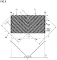
- FIG. 3 illustrates the magnetostrictive film 2 of the magnetic structure 20 seen in a direction orthogonal to the axis A (see FIG. 1 ).
- the pattern of the magnetostrictive film 2 illustrated in FIG. 3 is an example.
- the plurality of magnetostrictive lines 2a extend in directions intersecting the axis A when viewed in the direction orthogonal to the axis A.
- an interspace between adjacent ones of the magnetostrictive lines 2a is expressed as an interspace I.
- the magnetostrictive film 2 includes two regions 2b and 2c disposed side by side in the axial direction of the base material 21.
- the plurality of magnetostrictive lines 2a are formed across the two regions 2b and 2c.
- the magnetostrictive lines 2a in one region and the magnetostrictive lines 2a in the other region are symmetric with respect to the center line of the magnetostrictive film 2 in the axial direction. That is, each of the magnetostrictive lines 2a of the magnetostrictive film 2 is formed in a V shape when viewed in the direction orthogonal to the axis A (in the state illustrated in FIG. 3 ).
- the detection unit 30 includes the two cylindrical coils 3 and 4 and a yoke 5. As illustrated in FIG. 1 , the coils 3 and 4 are disposed to surround the magnetic structure 20. In the example of FIG. 1 , the coils 3 and 4 are disposed side by side in the axial direction with respect to the magnetic structure 20. Specifically, as illustrated in FIG. 1 , the coils 3 and 4 are disposed with respect to the magnetic structure 20 in such a manner that the coil 3 surrounds one region 2b of the magnetostrictive film 2 and the coil 4 surround the other region 2c of the magnetostrictive film 2.
- the yoke 5 has recesses in which the coils 3 and 4 are disposed. The coils 3 and 4 are disposed inside the tubular yoke 5.
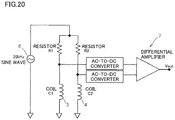
- the coils 3 and 4 are connected to an alternating current (AC) power supply 6 as illustrated in FIG. 20 to thereby generate an AC magnetic field around the coils 3 and 4.
- the coils 3 and 4, the yoke 5, and the base material 21 constitute a magnetic circuit.
- the coils 3 and 4 are also connected to a torque detection circuit 7.
- FIG. 20 illustrates an example configuration of an electronic circuit included in the torque sensor 1.
- the circuit configuration illustrated in FIG. 20 is widely known as the electronic circuit included in the torque sensor 1.
- the circuit illustrated in FIG. 20 includes the AC power supply 6 and the torque detection circuit 7.
- the AC power supply 6 applies an AC voltage to the coils 3 and 4.
- the torque detection circuit 7 detects a voltage generated in the coils 3 and 4 to thereby detect a torque generated in the base material 21.
- the torque detection circuit 7 obtains a voltage difference V out between the coils 3 and 4 and then, based on the difference V out , obtains the torque generated in the base material 21 by using an unillustrated arithmetic circuit.
- the electronic circuit included in the torque sensor 1 is not limited to the configuration illustrated in FIG. 20 .
- the arrangement of the components in the torque sensor 1 illustrated in FIG. 1 is an example.
- the numbers and arrangements, for example, of the coils 3 and 4 and the yoke 5 are not limited to those in the configuration illustrated in FIG. 1 , and may be changed as necessary by those skilled in the art.
- the length L/width W of the magnetostrictive lines 2a of the magnetostrictive film 2 illustrated in FIG. 3 satisfies Expression (2) below.
- the magnetostrictive lines 2a extend in a first direction intersecting the axis A when viewed in the direction orthogonal to the axis A in the region 2b of the magnetostrictive film 2.
- the magnetostrictive lines 2a extend in a second direction intersecting the first direction when viewed in the direction orthogonal to the axis A in the region 2c of the magnetostrictive film 2. That is, the magnetostrictive lines 2a have bending portions Z each bending at an angle ⁇ , in a center portion of the magnetostrictive film 2 in the axial direction of the base material 21.
- a coverage percentage of the magnetostrictive lines 2a defined in Equation (1) is 30% or more and 95% or less.
- the magnetostrictive lines 2a when viewed in the direction orthogonal to the axis A, extend from an end X of the magnetostrictive film 2 in the axial direction to the center portion (bending portions Z of the magnetostrictive lines 2a) of the magnetostrictive film 2 in the axial direction across the axis A, in the region 2b of the magnetostrictive film 2.
- the extension direction of the magnetostrictive lines 2a in the region 2b of the magnetostrictive film 2 corresponds to the first direction described above.
- the magnetostrictive lines 2a When viewed in the direction orthogonal to the axis A, the magnetostrictive lines 2a extend in a direction at an angle ⁇ relative to the first direction, that is, extend from the center portion (bending portions Z of the magnetostrictive lines 2a) of the magnetostrictive film 2 in the axial direction to the other end Y of the magnetostrictive film 2 in the axial direction across the axis A, in the region 2c of the magnetostrictive film 2.
- the extension direction of the magnetostrictive lines 2a in the region 2c of the magnetostrictive film 2 corresponds to the second direction described above.
- FIG. 3 illustrates an example of the magnetostrictive film 2 in which the magnetostrictive lines 2a have the bending portions Z.
- the bending portions Z are intersection of first portions 2m (magnetostrictive lines 2a in the region 2b) and second portions 2n (magnetostrictive lines 2a in the region 2c) of the magnetostrictive lines 2a. That is, in the magnetostrictive film 2 illustrated in FIG. 3 , each magnetostrictive line 2a includes the first portion 2m extending from one end X of the magnetostrictive film 2 in the axial direction to the bending portion Z and the second portion 2n extending from the bending portion Z to the other end Y of the magnetostrictive film 2 in the axial direction.
- the length L/width W of the magnetostrictive lines 2a is the sum of the length/width of the magnetostrictive lines 2a in the first portions 2m and the length/width of the magnetostrictive lines 2a in the second portions 2n.
- the length/width of each magnetostrictive line 2a in the first portion 2m can be obtained by (length L 1 of magnetostrictive line 2a from end X to bending portion Z illustrated in FIG. 3 )/(width of magnetostrictive line 2a in first portion 2m).
- each magnetostrictive line 2a in the second portion 2n can be obtained by (length L 2 of magnetostrictive line 2a from bending portion Z to end Y illustrated in FIG. 3 )/(width of magnetostrictive line 2a in second portion 2n).
- the torque sensor 1 having high sensitivity can be obtained. That is, in Equation (1), if the coverage percentage is 30% or more, sufficient sensitivity of the torque sensor 1 can be obtained. If the coverage percentage is 95% or less, the shape of the magnetostrictive film 2 does not vary easily. Accordingly, if the coverage percentage is 95% or less, adjacent ones of the magnetostrictive lines 2a do not contact each other, and thus, sufficient sensitivity of the torque sensor 1 can be obtained.
- the coverage percentage is preferably 50% or more.
- the coverage percentage is more preferably 60% or more.
- the coverage percentage is preferably 93% or less.
- the coverage percentage is more preferably 90% or less.
- the coverage percentage is much more preferably 85% or less.
- the torque sensor 1 having high sensitivity can be obtained.
- the length L/width W is 30 or more, sufficient sensitivity of the torque sensor 1 can be obtained.
- the magnetostrictive film 2 can be easily fabricated.
- the length L/width W is preferably less than 95.
- the length L/width W is more preferably less than 85.
- the length L/width W is preferably 43 or more.
- the length L/width W is more preferably 53 or more.
- the length L/width W is much more preferably 75 or more.
- the angle formed by the first direction and the second direction in the bending portion Z of the magnetostrictive line 2a is preferably 60° or more and 120° or less.
- the angle is more preferably 80° or more.
- the angle is preferably 100° or less.
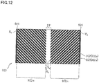
- the magnetostrictive line 2a does not have a bending portion (e.g., a magnetostrictive line 902a of a magnetostrictive film 902 illustrated in FIG. 12 )
- sensitivity of the torque sensor 1 can be further increased.
- the absolute value of an angle ⁇ 1 formed by the axis A and the first direction when viewed in the direction orthogonal to the axis A of the base material 21 is preferably 30° or more and 60° or less (more preferably the angle ⁇ 1 is ⁇ 45°) as illustrated in FIG. 3 .
- the absolute value of an angle ⁇ 2 formed by the base material 21 and the second direction is preferably 30° or more and 60° or less (more preferably angle ⁇ 2 is ⁇ 45°).
- the magnetostrictive film 2 illustrated in FIG. 3 further includes connecting parts 26 each connecting ends of adjacent ones of the magnetostrictive lines 2a in the axial direction.
- the connecting parts 26 are disposed at both axial ends of the magnetostrictive lines 2a. Since the connecting parts 26 connecting the plurality of magnetostrictive lines 2a are provided in the magnetostrictive film 2, the plurality of magnetostrictive lines 2a are not easily separated from the base material 21. Thus, strength of magnetostrictive film 2 can be enhanced.
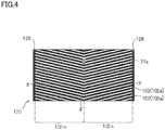
- FIGS. 4 through 12 illustrate other examples of the magnetostrictive lines 2a in the magnetostrictive film 2 of the magnetic structure 20 illustrated in FIG. 2 .
- a magnetostrictive film 102 illustrated in FIG. 4 is different from the magnetostrictive film 2 illustrated in FIG. 3 in the angle ⁇ formed by a first portion 102m and a second portion 102n of each magnetostrictive line 102a. More specifically, in the magnetostrictive film 102 illustrated in FIG. 4 , the angle ⁇ exceeds 90° (and less than 180°).
- reference numeral 120 denotes a magnetic structure.
- Reference numeral 126 denotes a connecting part.
- a magnetostrictive film 202 illustrated in FIG. 5 includes connecting parts 226 connecting ends of adjacent magnetostrictive lines 202a at both axial ends of the magnetostrictive line 202a.
- the magnetostrictive film 202 also includes a connecting part 226 connecting bending portions Z of adjacent magnetostrictive lines 202a.
- the connecting parts 226 connecting the bending portions Z of adjacent magnetostrictive lines 202a can further enhance the strength of the magnetostrictive film 202 including the plurality of magnetostrictive lines 202a.
- reference numeral 220 denotes a magnetic structure.
- Reference numeral 202m denotes a first portion of the magnetostrictive line 202a.
- Reference numeral 202n denotes a second portion of the magnetostrictive line 202a.
- connecting parts 326 connecting axial ends of adjacent magnetostrictive lines 2a connect both axial ends of magnetostrictive lines 302a and bending portions Z to one another.
- the magnetostrictive film 302 also includes a connecting part 326 connecting axial center portions of first portions 302m of adjacent magnetostrictive lines 302a and a connecting part 326 connecting axial center portions of second portions 302n of adjacent magnetostrictive lines 302a.
- the connecting parts 326 connecting the first portions 302m of adjacent magnetostrictive lines 302a or the second portions 302n of adjacent magnetostrictive lines 302a further enhance strength of the magnetostrictive film 302.
- reference numeral 320 denotes a magnetic structure.
- connecting parts 426 except connecting parts 426 connecting axial ends may connect only some of the plurality of magnetostrictive lines 402a.
- reference numeral 420 denotes a magnetic structure.
- Reference numeral 402 denotes a magnetostrictive film.
- Reference numeral 402a denotes a magnetostrictive line.
- Reference numeral 402m denotes a first portion of the magnetostrictive line 402a.
- Reference numeral 402n denotes a second portion of the magnetostrictive line 402a.
- a magnetostrictive film 502 may not include any connecting part.
- a magnetostrictive film 602 may include a plurality of magnetostrictive lines 602a provided only in a part of the outer peripheral surface of a base material.
- the interspace between adjacent magnetostrictive lines 702a in a magnetostrictive film 702 does not need to be uniform.
- a plurality of magnetostrictive lines 802a in a magnetostrictive film 802 does not need to have a uniform width W.
- the length L/width W defined in Expression (2) represents an average value of the length L/width W of each magnetostrictive line 802a.
- reference numeral 520 denotes a magnetic structure.
- Reference numeral 502a denotes a magnetostrictive line.
- Reference numeral 502m denotes a first portion of the magnetostrictive line 502a.
- Reference numeral 502n denotes a second portion of the magnetostrictive line 502a.
- reference numeral 626 denotes a connecting part.
- reference numeral 720 denotes a magnetic structure.
- Reference numeral 726 denotes a connecting part.
- reference numeral 826 denotes a connecting part.
- a magnetostrictive film 902 illustrated in FIG. 12 is a variation of the magnetostrictive film 2 illustrated in FIG. 3 .
- the bending portions Z of the magnetostrictive lines 2a illustrated in FIG. 2 are replaced by a gap 27 so that first portions 902m are separated from second portions 902n.
- magnetostrictive lines 902a are interrupted, and thus, a demagnetizing factor increases as compared to the configurations illustrated in FIGS. 3 through 11 . In this manner, sensitivity of the torque sensor becomes relatively lower than that of the configuration of the magnetostrictive film illustrated in FIG. 3 .
- the length L/width W defined by Expression (2) represents (distance from one end X 1 to the other end X 2 of the first portion 902m in the axial direction)/(width of the magnetostrictive line 902a in the first portion 902m) or (distance from one end Y 1 to the other end Y 2 of the second portion 902n in the axial direction)/(width of the magnetostrictive line 902a in the second portion 2n).
- reference numeral 920 denotes a magnetic structure.
- Reference numeral 926 denotes a connecting part.
- a magnetostrictive film 1002 illustrated in FIG. 13 is different from the magnetostrictive film 2 illustrated in FIG. 3 in positions of bending portions Z in the axial direction. More specifically, in the magnetostrictive film 2 illustrated in FIG. 3 , the length L 1 of the first portion 2m constituting each magnetostrictive line 2a is equal to the length L 2 of the second portion 2n constituting the magnetostrictive line 2a. In the magnetostrictive film 2 illustrated in FIG. 3 , in the axial direction, the magnetostrictive lines 2a are line symmetric with respect to the center line of the magnetostrictive film 2. On the other hand, in the magnetostrictive film 1002 illustrated in FIG.
- the length of the first portion 1002m is different from the length of the second portion 1002n (where FIG. 13 shows a case where the length of the first portion 1002m is larger than that of the second portion 1002n).
- the ratio of the first portion 1002m to the second portion 1002n is preferably 0.5 or more and 2 or less.
- reference numeral 1020 denotes a magnetic structure.
- Reference numeral 1026 denotes a connecting part.
- FIG. 14 schematically illustrates a cross section of the magnetic structure 20 illustrated in FIG. 1 .
- the cross section illustrated in FIG. 14 is obtained by cutting the magnetic structure 20 in a plane orthogonal to the extension direction of the magnetostrictive lines 2a. More specifically, the cross section illustrated in FIG. 14 is a cross section in a case where the magnetostrictive lines 2a are cut in a plane perpendicular to the first direction (i.e., direction from the end X of the magnetostrictive film 2 to the bending portions Z in FIG. 2 ), that is, a cross section taken along line C-C in FIG. 3 in a direction perpendicularly to the drawing sheet.
- the magnetic structure 20 includes the cylindrical base material 21 and the magnetostrictive film 2 disposed on the outer peripheral surface 21s of the base material 21.
- "M" corresponds to "W” in FIG. 3 .
- the magnetostrictive film 2 is made of a material including a magnetic material.
- the magnetic material is preferably a ferromagnetic material.
- the magnetic material preferably includes at least one of the metals selected from Ni, Fe, Co, and Cr. From the viewpoint of obtaining high magnetic permeability and high magnetostrictive effect, the magnetic material more preferably includes Fe and at least one of the metals selected from Ni, Co, and Cr.
- the magnetostrictive film 2 may further include a metal such as Al, Ti, Ge, Mo, Ag, or Cu or a nonmetal material such as Si, B, S, C, O, or N.
- the Fe content of the magnetostrictive film 2 is preferably 20 mass% or more and 40 mass% or less.
- the Fe content is more preferably 23 mass% or more.
- the Fe content is much more preferably 26 mass% or more.
- the Fe content is more preferably 36 mass% or less.
- the Fe content is much more preferably 33 mass% or less.
- the total content of metals except Fe is preferably 60 mass% or more and 80 mass% or less.
- the total content of metals except Fe is more preferably 64 mass% or more.
- the total content of metals except Fe is much more preferably 67 mass% or more.
- the total content of metals except Fe is more preferably 77 mass% or less.
- the total content of metals except Fe is much more preferably 74 mass% or less.
- the Ni content is preferably 60 mass% or more and 80 mass% or less.
- the Ni content is more preferably 64 mass% or more.
- the Ni content is much more preferably 67 mass% or more.
- the Ni content is more preferably 77 mass% or less.
- the Ni content is much more preferably 74 mass% or less.
- the S content of the magnetostrictive film 2 is preferably 0.03 mass% or more and 0.12 mass% or less.
- the S content is more preferably 0.04 mass% or more and 0.10 mass% or less.
- the S content is much more preferably 0.05 mass% or more and 0.09 mass% or less.
- the maximum thickness H of the magnetostrictive film 2 (the distance from the surface of the magnetostrictive film 2 contacting the base material 21, i.e., the outer peripheral surface 21s of the base material 21, to the tip of projection of the magnetostrictive film 2 outward in the radial direction of the base material 21) is 20 ⁇ m or more and 200 ⁇ m or less.
- the maximum thickness H is preferably 40 ⁇ m or more.
- the maximum thickness H is more preferably 60 ⁇ m or more.
- the maximum thickness H is preferably 140 ⁇ m or less.
- the maximum thickness H is more preferably 100 ⁇ m or less.
- the magnetostrictive lines 2a of the magnetostrictive film 2 When the magnetostrictive lines 2a of the magnetostrictive film 2 are viewed in a cross section taken orthogonally to the extension direction of the magnetostrictive lines 2a, the magnetostrictive lines 2a have portions outside in the radial direction of the base material 21 that are longer than portions of the magnetostrictive lines 2a near the base material 21 in the direction orthogonal to the radial direction of the base material 21 (direction parallel to the outer peripheral surface 21s of the base material 21). Specifically, the magnetostrictive lines 2a have projections 2e projecting from bodies of the magnetostrictive lines 2a on the base material 21 in opposite directions orthogonal to the radial direction of the base material 21. The presence of the projections 2e of the magnetostrictive lines 2a increases the surface area of the magnetostrictive lines 2a.
- an angle ⁇ e formed by the interface between the magnetostrictive lines 2a and the base material 21 and the projecting direction of the projections 2e is preferably an acute angle (less than 90°).
- the angle ⁇ e is more preferably greater than 0° and less than or equal to 45°.
- the angle ⁇ e is much more preferably 30° or less.
- the width M at a predetermined distance from the outer peripheral surface 21s of the base material 21 in the radial direction of the base material 21 is larger than a width N of a contact area 2f between the magnetostrictive film 2 and the outer peripheral surface 21s of the base material 21.
- the plurality of magnetostrictive lines 2a of the magnetostrictive film 2 have the length of the longest portion (length M at the predetermined distance described above, which will be hereinafter referred to as a maximum width M) that is larger than the length N of the contact area 2f between the magnetostrictive film 2 and the outer peripheral surface 21s of the base material 21, in the direction orthogonal to the radial direction of the base material 21.
- the maximum width M is larger than the length of the interspace D between adjacent magnetostrictive lines 2a.
- the interspace D between adjacent magnetostrictive lines 2a refers to an interspace from the contact area 2f between the magnetostrictive line 2a and the base material 21 to the contact area 2f between its adjacent magnetostrictive line 2a and the base material 21.
- the magnetostrictive lines 2a having the shape described above can enhance sensitivity of the torque sensor 1. That is, when the magnetostrictive lines 2a are viewed in the cross section taken orthogonally to the extension direction of the magnetostrictive lines 2a, the maximum width M of the magnetostrictive lines 2a in the magnetostrictive film 2 is larger than the length of the interspace D between adjacent magnetostrictive lines 2a. In such a configuration, the interspace D between the magnetostrictive lines 2a is relatively narrow.
- the maximum width M of the magnetostrictive lines 2a can be made larger than the length N of the contact area 2f between the magnetostrictive film 2 and the outer peripheral surface 21s of the base material 21 so that the surface area of the magnetostrictive lines 2a, that is, the surface area of the magnetostrictive film 2, can be increased.
- the increase in the surface area of the magnetostrictive film 2 enables the magnetic permeability of the magnetostrictive film 2 to vary in a wide range. In this manner, a change in magnetic permeability upon application of a force to the magnetostrictive film 2 can be easily detected. Thus, sensitivity of the torque sensor 1 can be enhanced.
- sensitivity of the torque sensor 1 can be enhanced without changes in the coverage percentage defined in Equation (1) and the value of length L/width W defined in Expression (2).
- the length of the interspace D from the contact area 2f between one magnetostrictive line 2a and the outer peripheral surface 21s of the base material 21 to the contact area 2f between its adjacent magnetostrictive line 2a and the outer peripheral surface 21s of the base material 21 is larger than the sum of the length of the projection 2e of one magnetostrictive line 2a projecting toward its adjacent magnetostrictive line 2a and the length of the projection 2e of the adjacent magnetostrictive line 2a projecting toward the magnetostrictive line 2a.
- the magnetostrictive lines 2a When the magnetostrictive lines 2a are viewed in the cross section illustrated in FIG. 14 , the magnetostrictive lines 2a has a maximum width M larger than the height (maximum thickness) H of the magnetostrictive lines 2a in the thickness direction. In this manner, the magnetostrictive lines 2a are formed in a flat shape that is longer in the direction (direction parallel to the outer peripheral surface 21s of the base material 21) orthogonal to the radial direction of the base material 21 than in the thickness direction. Accordingly, the surface area of the magnetostrictive lines 2a can be further increased. Thus, a change in magnetic permeability upon application of a force to the magnetostrictive film 2 can be more easily detected.
- the ratio H 1 /H between the maximum thickness H of the magnetostrictive line 2a and the height of ends me of the magnetostrictive line 2a is less than one.
- the H 1 /H is preferably 0.8 or less.
- the H 1 /H is more preferably 0.5 or less.
- the H 1 /H is much more preferably 0.3 or less.
- the H 1 /H is preferably 0.015 or more.
- the magnetostrictive lines 2a are formed in such a manner that the ratio H 1 /H is within the ranges described above so that the surface area of the magnetostrictive lines 2a can be further increased. Thus, a change in magnetic permeability upon application of a force to the magnetostrictive film 2 can be more easily detected.
- H 1 /H By setting H 1 /H at 0.5 or less, that is, by setting a half height of the maximum thickness H of the magnetostrictive lines 2a at a position higher than or equal to the maximum width M from the outer peripheral surface 21s of the base material 21, a portion having a width larger than that of the contact area 2f between the magnetostrictive line 2a and the outer peripheral surface 21s of the base material 21 can be provided in a wide range in the thickness direction of the magnetostrictive line 2a. Accordingly, the surface area of the magnetostrictive lines 2a can be further increased. Thus, a change in magnetic permeability upon application of a force to the magnetostrictive films 2 can be more easily detected.
- FIGS. 17 , 18 , and 19 is a cross-sectional view (cross-sectional view taken along a plane orthogonal to the extension direction of the magnetostrictive lines 2a) illustrating another example of the magnetic structure by using a cross section similar to that of FIG. 2 .
- FIGS. 17 , 18 , and 19 illustrates a case where the angle ⁇ e formed by the outer peripheral surface 21s of the base material 21 and the projection direction of projections 2002e, 3002e, or 4002e of magnetostrictive lines 2002a, 3002a, or 4002a and the ratio H 1 /H are different from those of the example illustrated in FIG. 14 (specifically the angles ⁇ e are 20°, 5°, and 3°, and the ratios H 1 /H are 0.5, 0.2, and 0.1, respectively).
- the surface area of the magnetostrictive lines 5002a are smaller than those of the magnetostrictive lines 2002a, 3002a, and 4002a having cross sections illustrated in FIGS. 14 and 17 through 19 .
- sensitivity of the torque sensor is lower than those of the magnetostrictive lines 2002a, 3002a, and 4002a having the cross sections illustrated in FIGS. 14 and 17 through 19 .
- the base material 21 is made of a material having a composition different from that of the magnetostrictive film 2, and is, for example, made of a material having a magnetic permeability lower than that of the magnetostrictive film 2.
- the base material 21 is preferably made of a magnetic material, and is more preferably made of a ferromagnetic material such as Fe, Ni, Co, or Cr.
- the base material 21 may contain a metal such as Al, Ti, Ge, Mo, Ag, or Cu or a nonmetal material such as Si, B, S, C, O, or N.
- the magnetic structure 20 may further include a resist layer formed on the surface of the magnetostrictive film 2.
- the resist layer preferably has a thickness of 45 ⁇ m or less.
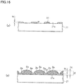
- FIGS. 16(a) and 16(b) are views for describing a method for fabricating a magnetic structure 20.
- FIG. 16 is a cross-sectional view taken along the same plane as that in FIG. 14 , and illustrates the base material 21, the magnetostrictive film 2, the resist layer 91, and so forth in the process of fabricating the magnetic structure 20.
- the method for fabricating a magnetic structure 20 includes the step of forming a resist layer 91 having a predetermined pattern on an outer peripheral surface 21s of a base material 21 and the step of forming a magnetostrictive film 2 on the outer peripheral surface 21s of the base material 21 on which the resist layer 91 is disposed.
- the method for fabricating the magnetic structure 20 will now be specifically described.
- the resist layer 91 having a predetermined pattern is formed on the outer peripheral surface 21s of the base material 21.
- This resist layer 91 is used for forming magnetostrictive lines 2a illustrated in FIGS. 1 , 2 , and 3 through 12 .
- the resist layer 91 can be formed by, for example, a known method such as water transfer or screen printing.
- the thickness of the resist layer 91 is, for example, 3 ⁇ m or more and 45 ⁇ m or less.
- an angle ⁇ f formed by the outer peripheral surface 21s of the base material 21 and an end of the resist layer 91 is preferably an obtuse angle (exceeding 90°).
- a magnetostrictive film 2 is formed on the surface of the base material 21 on which the resist layer 91 is provided.
- the magnetostrictive film 2 is formed in such a manner that a height H of the magnetostrictive film 2 exceeds a height H 1 of the resist layer 91.
- the formation of the magnetostrictive film 2 may employ a known method such as sputtering, CVD, or plating.
- a heat treatment is preferably performed at a predetermined temperature (e.g., 300°C or more and 1,000°C or less) for a predetermined time (e.g., one minute or more and 48 hours or less).
- a predetermined temperature e.g. 300°C or more and 1,000°C or less
- a predetermined time e.g., one minute or more and 48 hours or less.
- the magnetostrictive film 2 is deposited and is subjected to a heat treatment.
- the magnetic structure 20 having high sensitivity can be obtained with a simple method and a short process.
- fabrication costs of the magnetic structure 20 can be reduced.
- An electric motor-assisted bicycle (e.g., a bicycle, a tricycle, or a four-wheel vehicle) according to an embodiment of the present invention includes the torque sensor 1 according to the embodiment described above.
- the torque sensor 1 detects a torque generated when an occupant pedals.
- driving of an electric motor is controlled.
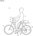
- FIG. 21 schematically illustrates a configuration of the electric motor-assisted bicycle 10 as an example of an electrically assisted vehicle according to the present invention.
- left and right, front and rear, and top and bottom are based on a state in which an occupant 71 sits on a saddle 34 of the electric motor-assisted bicycle 10, facing the handle bar 77 thereof.
- the electric motor-assisted bicycle 10 includes a frame 12.
- the frame 12 includes a head pipe 14, an upper pipe 16, a front pipe 18, a seat pipe 70, a pair of rear pipes 72, and a pair of lower pipes 74.
- the upper pipe 16 extends from the head pipe 14 rearward and horizontally.
- the front pipe 18 extends from the head pipe 14 rearward and obliquely downward.
- the seat pipe 70 connects the rear end of the upper pipe 16 to the rear end of the front pipe 18.
- the pair of rear pipes 72 extends from the connecting point between the upper pipe 16 and the seat pipe 70 rearward and obliquely downward.
- the pair of lower pipes 74 extends from the connecting point between the front pipe 18 and the seat pipe 70 rearward and horizontally.
- the rear ends of the pair of rear pipes 72 are connected to the rear ends of the pair of lower pipes 74.
- a steering shaft 76 for changing the travelling direction of the vehicle is disposed along the head pipe 14.
- the steering shaft 76 is rotatable in the head pipe 14.
- the handle bar 77 is attached to the upper end of the steering shaft 76.
- a pair of left and right front forks 80 is attached to the lower end of the steering shaft 76.
- a front wheel 82 is attached to the lower end of the front forks 80.
- the front wheel 82 is rotatable about the center axis of the front wheel 82 supported by the front forks 80.
- the saddle 34 is disposed at the upper end of the seat pipe 70.
- a carrier 36 is fixed to the seat pipe 70 and extends rearward therefrom.
- FIG. 22 schematically illustrates a configuration of the motor-driven unit 38 of the electric motor-assisted bicycle 10.
- the motor-driven unit 38 includes the torque sensor 1 according to the embodiment described above. More specifically, as illustrated in FIG. 22 , the motor-driven unit 38 includes a crank shaft 40, a driving sprocket 42, a crank angle sensor 44, the torque sensor 1, an electric motor 48, and a controller 50.
- the motor-driven unit 38 may be configured to be attachable to a bicycle that is not an electric motor-assisted bicycle or may be configured to be interchangeable with an existing motor-driven unit of an electric motor-assisted bicycle.
- the pedal 54 is attached to the crank shaft 40 through a crank 52.
- the driving sprocket 42 (see FIG. 22 ) is attached to the outer peripheral surface of the crank shaft 40.
- the driving sprocket 42 is connected to a rear-wheel sprocket 58 through an endless chain 56.
- a rear wheel 62 is attached to the rear-wheel sprocket 58 through a rotating shaft 60.
- the rear wheel 62 is rotatable about the rotating shaft 60.
- crank angle sensor 44 and the torque sensor 1 are disposed near the crank shaft 40.
- the crank angle sensor 44 detects a crank angle ⁇ c that is a rotation angle of the crank shaft 40 rotating by operation of the pedal 54.
- the torque sensor 1 detects a crank torque ⁇ that is a torque applied to the crank shaft 40.
- the electric motor 48 generates an auxiliary driving force to be applied to the driving sprocket 42.
- the controller 50 includes a CPU 64 and a memory 66.
- the CPU 64 performs a necessary computation and controls operations of the electric motor 48 and the electric motor-assisted bicycle 10.
- the memory 66 as a storage unit is constituted by, for example, an EEPROM, and stores programs and data for controlling an operation of the electric motor-assisted bicycle 10, computation data, and so forth.
- the memory 66 stores an assist pattern.
- the CPU 64 of the controller 50 receives the crank angle ⁇ c output from the crank angle sensor 44 and the crank torque ⁇ output from the torque sensor 1. These data items are stored in the memory 66.
- the CPU 64 controls an auxiliary driving force generated by the electric motor 48.
- the electric motor-assisted bicycle 10 includes the torque sensor 1 according to the embodiment described above that can accurately detect a torque with high sensitivity, and thus, the electric motor-assisted bicycle 10 can travel with stability.
- the torque sensor 1 includes the tubular base material 21 extending along the axis A and the magnetostrictive film 2 formed on the outer peripheral surface 21s of the base material 21.
- the magnetostrictive film 2 includes the plurality of magnetostrictive lines 2a each extending linearly.
- the length M of a longest portion of one of the magnetostrictive lines 2a is larger than the length N of a contact area 2f between the one of the magnetostrictive lines 2a and the outer peripheral surface 21s of the base material 21, and is larger than the length of the interspace D between the contact area 2f and another contact area 2f, in a direction parallel to the outer peripheral surface 21s of the base material 21, and the another contact area 2f is between one of the magnetostrictive lines 2a adjacent to the one of the magnetostrictive lines 2a and the outer peripheral surface 21s of the base material 21 (i.e., the interspace D between adjacent ones of the magnetostrictive lines 2a).
- the length M of the longest portion of each of the magnetostrictive lines 2a in the direction parallel to the outer peripheral surface 21s of the base material 21 is larger than the length of the interspace D between adjacent ones of the magnetostrictive lines 2a.
- the interspace D between the magnetostrictive lines 2a is relatively narrow.
- the length M of the longest portion is made larger than the length N of the contact area 2f between each magnetostrictive line 2a and the outer peripheral surface 21s of the base material 21 so that the surface area of the magnetostrictive lines 2a can be increased.
- a change in magnetic permeability upon application of a force to the magnetostrictive film 2 can be easily detected.
- sensitivity of the torque sensor 1 can be enhanced under dimensional constraints on the magnetostrictive film 2.
- the length M of the longest portion is larger than the maximum thickness H of the magnetostrictive lines 2a.
- each of the magnetostrictive lines 2a is formed in a flat shape that is longer in the direction parallel to the outer peripheral surface 21s of the base material 21 than in the thickness direction of the magnetostrictive line 2a. Accordingly, the surface area of the magnetostrictive lines 2a can be further increased. Thus, a change in magnetic permeability upon application of a force to the magnetostrictive film 2 can be more easily detected. As a result, sensitivity of the torque sensor 1 can be further enhanced under dimensional constraints on the magnetostrictive film 2.
- the maximum thickness H of each of the magnetostrictive lines 2a is larger than the height H 1 in the thickness direction from the outer peripheral surface 21s of the base material 21 to the longest portion of the base material 21.
- the magnetostrictive lines 2a including the some of the magnetostrictive lines 2a are viewed in the cross section taken orthogonally to the extension direction of the magnetostrictive lines 2a, a portion wider than the contact area 2f with the outer peripheral surface 21s of the base material 21 can be formed. Accordingly, the surface area of the magnetostrictive lines can be increased, as compared to magnetostrictive lines not having a portion wider than the contact area 2f with the outer peripheral surface 21s of the base material 21. Thus, a change in magnetic permeability upon application of a force to the magnetostrictive film 2 can be easily detected. As a result, sensitivity of the torque sensor 1 can be further enhanced under dimensional constraints on the magnetostrictive film 2.
- a half of the maximum thickness M of the magnetostrictive lines 2a is greater than or equal to the height H 1 in the thickness direction from the outer peripheral surface 21s of the base material 21 to the longest portion of the base material 21.
- the length of the interspace D from the contact area 2f of one of the magnetostrictive lines 2a and the contact area 2f between one of the magnetostrictive lines 2a adjacent to the one of the magnetostrictive lines 2a and the outer peripheral surface 21s of the base material 21 is larger than the sum of the length of the longest portion projecting from the contact area 2f toward the adjacent magnetostrictive line 2a and the length of the longest portion of the adjacent magnetostrictive line 2a from the contact area 2f between the adjacent magnetostrictive line 2a and the base material 21 toward the one of the magnetostrictive lines 2a, in the direction parallel to the outer peripheral surface 21s of the base material 21.
- the magnetostrictive film 2 includes the connecting parts 26 connecting the plurality of magnetostrictive lines 2a. With this configuration, the magnetostrictive lines 2a are not easily separated from the base material 21. Thus, strength of the magnetostrictive film 2 can be enhanced.
- the torque sensor 1 further includes the coils 3 and 4 disposed to surround the magnetostrictive film 2. Accordingly, a change in magnetic permeability occurring in the magnetostrictive film 2 can be detected based on a change in impedance of the coils 3 and 4.
- the plurality of coils 3 and 4 are arranged side by side along the axis A.
- the plurality of coils 3 and 4 ensure detection of a change in magnetic permeability of the magnetostrictive film 2. Accordingly, detection accuracy of the torque sensor 1 can be enhanced.
- the configuration of the embodiment is applied to the torque sensor 1 as an example of the magnetostrictive sensor.
- the configuration of this embodiment may be applied to other sensors such as a load sensor as long as the sensor includes a magnetostrictive film.
- the configuration of the embodiment may be applied not only to a torque sensor for use in an electric motor-assisted bicycle but also sensors for other purposes.
- the base material 21 is cylindrical.
- the base material 21, however, may have any cross-sectional shape as long as the base material 21 is tubular or columnar.
- the magnetostrictive lines 2a of the magnetostrictive film 2 extend in lines. However, at least a part of the plurality of island-shape magnetostrictive portion may be connected together in lines.
- the plurality of magnetostrictive lines 2a may not be parallel to one another as long as the magnetostrictive lines 2a are not in contact with one another.
- the plurality of magnetostrictive lines 2a of the magnetostrictive film 2 have the same cross section as that illustrated in FIG. 14 across the extension direction thereof.
- the cross sections of the magnetostrictive lines 2a may differ from one another in each of the magnetostrictive lines 2a in the extension direction thereof. All the plurality of magnetostrictive lines 2a do not need to have the same cross-sectional shape.
- the magnetostrictive lines 2a in the cross section taken orthogonally to the extension direction of the magnetostrictive lines 2a, the magnetostrictive lines 2a have the projections 2e projecting to opposite directions parallel to the outer peripheral surface 21s of the base material 21.
- the magnetostrictive lines 2a may have projections projecting in one direction parallel to the outer peripheral surface 21s s of the base material 21.
- the length M of the longest portion in the direction parallel to the outer peripheral surface 21s of the base material 21 is larger than the maximum thickness H of the magnetostrictive lines 2a.
- the length M of the longest portion may be less than or equal to the maximum thickness H.
- a half of the maximum thickness H of the magnetostrictive lines 2a is greater than or equal to the height H 1 in the thickness direction from the outer peripheral surface 21s of the base material 21 to the longest portion of the base material 21.
- the half of the maximum thickness M may be smaller than the height H 1 .
- the magnetic structure 20 including the magnetostrictive film 2 having the magnetostrictive lines 2a illustrated in FIG. 3 and the cross section illustrated in FIG. 14 and formed by plating was obtained.
- the plating was performed with a known Ni-Fe alloy bath (Watts bath) using nickel sulfate, nickel chloride, iron sulfate (II), boric acid, or the like.
- Plating conditions were pH3, a bath temperature of 55°C, and a current density of 5 to 20 A/dm 2 .
- the plating was performed with the base material 21 being circumferentially rotated at 3 rpm, and thereby a uniform thickness of the resulting plating film (magnetostrictive film 2) was obtained.
- the obtained magnetostrictive film 2 was subjected to a heat treatment at 500°C for one hour under a nitrogen atmosphere.
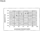
- the magnetostrictive lines 2a in cross section had a maximum thickness H of 85 ⁇ m, a width M of 460 ⁇ m, a length N in an interface with the base material 21 of 260 ⁇ m, a coverage percentage of 17%, 30%, 52%, 70%, or 79% ( FIG. 23 ), a length L/width W of the magnetostrictive lines 2a of 12, 25, 32, 36, 43, 54, 64, 75, 84, 95, or 120 ( FIG. 24 ).
- the angle ⁇ formed by the first direction and the second direction was 90°. As illustrated in FIG.
- the angle ⁇ 1 formed by the axis A of the base material 21 and the first direction was 45°.
- the angle ⁇ 2 formed by the axis A of the base material 21 and the second direction was 45°.
- the interspace I between adjacent magnetostrictive lines 2a was 200 ⁇ m.
- the resist layer 91 used for fabricating the magnetostrictive film 2 had a thickness of 20 ⁇ m.
- the obtained magnetostrictive film 2 was a Fe-Ni alloy.
- the magnetostrictive film 2 had a Fe concentration of 30 mass% and a Ni concentration of 70 mass%.
- a material for the base material 21 was SCM435 (JIS G4053). Using the magnetic structure 20 obtained in this example, the torque sensor 1 having the configuration illustrated in FIG. 1 was fabricated.
- the sensitivity of the torque sensor 1 was measured by connecting the torque sensor 1 to the circuit illustrated in FIG. 20 and applying a torque of 80 Nm.
- each of a resistor R1 and a resistor R2 was a resistor having a resistance value of 15 ⁇ .
- Each of coils C1 and C2 was configured by winding, 124 times, a copper wire having a diameter of 0.2 mm and provided with an insulating coating.
- FIG. 23 is a graph showing a relationship between a coverage percentage of the magnetic structure 20 (abscissa) and sensitivity of the torque sensor 1 (ordinate) in the torque sensor 1 according to this example. From FIG. 23 , it can be understood that excellent sensitivity can be obtained with a coverage percentage of 30% or more and 95% or less.
- FIG. 24 is a graph showing a relationship between the length L/width W of the magnetostrictive film pattern 2a of a magnetic structure 20 (abscissa) and sensitivity of the torque sensor 1 (ordinate) in the torque sensor 1 according to this example (coverage percentage: 70%). From FIG. 24 , it can be understood that sensitivity significantly decreases if the length L/width W is less than 30.
- FIG. 25 is a graph showing a relationship between the height H 1 of an end of the magnetostrictive film 2 /the maximum thickness H of the magnetostrictive film 2 in the magnetic structure 20 (abscissa) and the sensitivity of the torque sensor 1 (ordinate) in the torque sensor 1 according to this example.
- the maximum thickness H of the magnetostrictive film 2 was 85 ⁇ m and the thickness of the resist layer 21 was changed in the range from 3 to 45 ⁇ m.
- a plurality of torque sensors 1 having different heights H 1 of ends of magnetostrictive films 2 and different angles ⁇ e were fabricated. From FIG. 25 , it can be understood that as the ratio H 1 /H decreases, sensitivity of the torque sensor 1 increases.
- Magnetic structures having the magnetostrictive lines illustrated in FIGS. 5 through 11 and 13 and the cross section illustrated in FIG. 14 were obtained in the same manner as that of the first example, except that the magnetostrictive films 2 had patterns illustrated in FIGS. 5 through 11 and 13 .
- the torque sensors including the magnetic structures according to this example had sensitivities substantially equal to those of the torque sensors 1 according to the first example.
- a magnetic structure having the magnetostrictive lines illustrated in FIG. 12 and the cross section illustrated in FIG. 14 was obtained in the same manner as that of the first example, except that the magnetostrictive films 2 had the pattern illustrated in FIG. 12 .
- the torque sensor including the magnetic structure according to this example shows sensitivity slightly inferior to that of the torque sensor 1 according to the first example but shows high sensitivity.
- a magnetic structure having the magnetostrictive lines 2a illustrated in FIG. 3 and the cross section illustrated in FIG. 15 was obtained in the same manner as that of the first example, except that the resist layer 91 for forming the magnetostrictive film 2 had a thickness of 50 ⁇ m and the magnetostrictive film 2 had a thickness of 45 ⁇ m.
- the torque sensor including the magnetic structure according to this example had a sensitivity that is about 1/3 of that of the torque sensor 1 according to the first example.
- the present invention is applicable to, for example, a magnetostrictive sensor for use in an electric motor-assisted bicycle.
Landscapes
- Physics & Mathematics (AREA)
- Electromagnetism (AREA)
- General Physics & Mathematics (AREA)
- Engineering & Computer Science (AREA)
- Chemical & Material Sciences (AREA)
- Combustion & Propulsion (AREA)
- Transportation (AREA)
- Mechanical Engineering (AREA)
- Power Steering Mechanism (AREA)
- Force Measurement Appropriate To Specific Purposes (AREA)
- Measuring Magnetic Variables (AREA)
Applications Claiming Priority (3)
| Application Number | Priority Date | Filing Date | Title |
|---|---|---|---|
| JP2015125842 | 2015-06-23 | ||
| JP2015125843 | 2015-06-23 | ||
| PCT/JP2016/068719 WO2016208687A1 (fr) | 2015-06-23 | 2016-06-23 | Capteur magnétostrictif, structure magnétique et son procédé de production, unité d'entraînement motorisé pourvue d'un capteur magnétostrictif, et bicyclette assistée à moteur |
Publications (3)
| Publication Number | Publication Date |
|---|---|
| EP3315933A1 true EP3315933A1 (fr) | 2018-05-02 |
| EP3315933A4 EP3315933A4 (fr) | 2018-06-20 |
| EP3315933B1 EP3315933B1 (fr) | 2019-10-30 |
Family
ID=57585082
Family Applications (2)
| Application Number | Title | Priority Date | Filing Date |
|---|---|---|---|
| EP16814456.6A Active EP3315933B1 (fr) | 2015-06-23 | 2016-06-23 | Capteur magnétostrictif, structure magnétique et son procédé de production, unité d'entraînement motorisé pourvue d'un capteur magnétostrictif, et bicyclette assistée à moteur |
| EP16814457.4A Active EP3315934B1 (fr) | 2015-06-23 | 2016-06-23 | Structure magnétique, capteur magnétostrictif, unité de moteur d'entrainement et vélo assisté par moteur comprenant le capteur magnétostrictif |
Family Applications After (1)
| Application Number | Title | Priority Date | Filing Date |
|---|---|---|---|
| EP16814457.4A Active EP3315934B1 (fr) | 2015-06-23 | 2016-06-23 | Structure magnétique, capteur magnétostrictif, unité de moteur d'entrainement et vélo assisté par moteur comprenant le capteur magnétostrictif |
Country Status (4)
| Country | Link |
|---|---|
| US (2) | US10502646B2 (fr) |
| EP (2) | EP3315933B1 (fr) |
| JP (3) | JP6698082B2 (fr) |
| WO (2) | WO2016208688A1 (fr) |
Cited By (1)
| Publication number | Priority date | Publication date | Assignee | Title |
|---|---|---|---|---|
| US20230408353A1 (en) * | 2020-11-13 | 2023-12-21 | Zf Friedrichshafen Ag | Method for producing a deformation body for measuring a force and/or a torque for a roll stabilization system for a vehicle, and deformation body |
Families Citing this family (13)
| Publication number | Priority date | Publication date | Assignee | Title |
|---|---|---|---|---|
| JP6698082B2 (ja) * | 2015-06-23 | 2020-05-27 | ヤマハ発動機株式会社 | 磁歪式センサ、磁性構造体およびその製造方法、ならびに、磁歪式センサを備えたモータ駆動ユニットおよび電動アシスト付き自転車 |
| JP6661502B2 (ja) * | 2016-09-23 | 2020-03-11 | 本田技研工業株式会社 | 磁歪式トルクセンサ、及び磁歪式トルクセンサの製造方法 |
| JP7149325B2 (ja) * | 2017-05-05 | 2022-10-06 | 捷安特電動車(昆山)有限公司 | 乗物の運転パラメータの検出装置 |
| CN108791681A (zh) * | 2017-05-05 | 2018-11-13 | 捷安特电动车(昆山)有限公司 | 一种测量中轴双边力矩、位置角度、转速及功率的装置 |
| CN108801297A (zh) * | 2017-05-05 | 2018-11-13 | 捷安特电动车(昆山)有限公司 | 一种检测中轴双边力矩、位置角度、转速及功率的装置 |
| CN108839751B (zh) * | 2018-05-23 | 2024-03-22 | 铂金橙智能科技(太仓)有限公司 | 同轴中置驱动电机系统及助力车 |
| CN110190211B (zh) | 2018-12-29 | 2020-03-31 | 比亚迪股份有限公司 | 电池托盘、动力电池包及车辆 |
| CN111384328A (zh) | 2018-12-29 | 2020-07-07 | 比亚迪股份有限公司 | 电池托盘、动力电池包及车辆 |
| US12230820B2 (en) | 2019-01-09 | 2025-02-18 | Byd Company Limited | Power battery pack and electric vehicle |
| JP7357570B2 (ja) * | 2020-03-03 | 2023-10-06 | 株式会社プロテリアル | 磁歪式トルクセンサの検出回路及び検出方法 |
| JP7510157B2 (ja) * | 2020-07-27 | 2024-07-03 | 国立大学法人東北大学 | センサユニットおよびセンサ |
| JP7567307B2 (ja) * | 2020-09-16 | 2024-10-16 | 日本精工株式会社 | 自転車 |
| TWI866777B (zh) * | 2024-02-07 | 2024-12-11 | 達方電子股份有限公司 | 自行車中軸 |
Family Cites Families (28)
| Publication number | Priority date | Publication date | Assignee | Title |
|---|---|---|---|---|
| JPS60254679A (ja) * | 1984-05-30 | 1985-12-16 | Nissan Motor Co Ltd | トルク検出装置 |
| DE3509552A1 (de) * | 1985-03-16 | 1986-09-18 | Vacuumschmelze Gmbh, 6450 Hanau | Ferromagnetische folie fuer einen drehmomentsensor |
| US4823620A (en) | 1986-02-10 | 1989-04-25 | Nissan Motor Company, Ltd. | Magnetostrictive device for measuring torsional torque |
| GB2210460B (en) * | 1987-07-29 | 1991-08-21 | Nissan Motor | Magnetostrictive stress measurement apparatus |
| US4852411A (en) * | 1988-12-21 | 1989-08-01 | Eaton Corporation | Torque sensor |
| US5313845A (en) * | 1989-05-31 | 1994-05-24 | Mitsubishi Denki Kabushiki Kaisha | Strain detector |
| JPH032638A (ja) * | 1989-05-31 | 1991-01-09 | Mitsubishi Electric Corp | 歪検出器 |
| US5201964A (en) * | 1989-06-21 | 1993-04-13 | The United States Of America As Represented By The Secretary Of The Navy | Magnetostrictive torque sensor |
| JP2800347B2 (ja) | 1990-02-07 | 1998-09-21 | 株式会社豊田自動織機製作所 | 磁歪式トルクセンサ |
| EP0502721B1 (fr) | 1991-03-04 | 1995-12-27 | Matsushita Electric Industrial Co., Ltd. | Détecteur de couple de rotation sans contact |
| JP2765340B2 (ja) * | 1991-07-12 | 1998-06-11 | 日産自動車株式会社 | 被測定軸,トルク検出装置および被測定軸の製造方法 |
| JP2765263B2 (ja) * | 1991-04-30 | 1998-06-11 | 日産自動車株式会社 | トルク検出装置 |
| US5280729A (en) | 1991-04-30 | 1994-01-25 | Nissan Motor Co., Ltd. | Magnetostrictive torque detecting apparatus |
| JP3114455B2 (ja) * | 1993-02-02 | 2000-12-04 | 三菱マテリアル株式会社 | 磁歪式トルク検出部を有するシャフトおよびその製造方法 |
| US5585574A (en) | 1993-02-02 | 1996-12-17 | Mitsubishi Materials Corporation | Shaft having a magnetostrictive torque sensor and a method for making same |
| JP3018812B2 (ja) * | 1993-02-12 | 2000-03-13 | 三菱マテリアル株式会社 | 磁歪式トルク検出部を有するシャフトの製造方法 |
| JPH098378A (ja) * | 1995-06-14 | 1997-01-10 | Alps Electric Co Ltd | 磁歪素子 |
| JPH11344394A (ja) * | 1998-05-29 | 1999-12-14 | Toyota Autom Loom Works Ltd | トルクセンサ |
| JP2004184189A (ja) * | 2002-12-02 | 2004-07-02 | Yamaha Motor Co Ltd | 磁歪式トルクセンサ |
| JP2004264188A (ja) * | 2003-03-03 | 2004-09-24 | Moric Co Ltd | 磁歪トルクセンサ |
| JP2004340783A (ja) * | 2003-05-16 | 2004-12-02 | Ntn Corp | トルク検出装置 |
| US7564152B1 (en) * | 2004-02-12 | 2009-07-21 | The United States Of America As Represented By The Secretary Of The Navy | High magnetostriction of positive magnetostrictive materials under tensile load |
| US7401531B2 (en) * | 2005-09-23 | 2008-07-22 | Continental Automotive Systems Us, Inc. | Fabrication of a magnetoelastic torque sensor |
| JP4932206B2 (ja) | 2005-09-27 | 2012-05-16 | 本田技研工業株式会社 | 磁歪式トルクセンサの製造方法 |
| JP4936969B2 (ja) | 2007-04-17 | 2012-05-23 | 株式会社東芝 | 磁歪式トルクセンサシャフトの製造装置 |
| JP6698082B2 (ja) * | 2015-06-23 | 2020-05-27 | ヤマハ発動機株式会社 | 磁歪式センサ、磁性構造体およびその製造方法、ならびに、磁歪式センサを備えたモータ駆動ユニットおよび電動アシスト付き自転車 |
| EP3343191B1 (fr) * | 2015-10-01 | 2021-08-25 | Yamaha Hatsudoki Kabushiki Kaisha | Capteur magnétostrictif |
| JP6413027B2 (ja) * | 2015-10-01 | 2018-10-24 | ヤマハ発動機株式会社 | 磁歪式トルクセンサ |
-
2016
- 2016-06-23 JP JP2017524980A patent/JP6698082B2/ja active Active
- 2016-06-23 WO PCT/JP2016/068720 patent/WO2016208688A1/fr not_active Ceased
- 2016-06-23 WO PCT/JP2016/068719 patent/WO2016208687A1/fr not_active Ceased
- 2016-06-23 JP JP2017524979A patent/JP6373497B2/ja active Active
- 2016-06-23 EP EP16814456.6A patent/EP3315933B1/fr active Active
- 2016-06-23 EP EP16814457.4A patent/EP3315934B1/fr active Active
-
2017
- 2017-12-22 US US15/852,700 patent/US10502646B2/en active Active
- 2017-12-22 US US15/853,119 patent/US10184847B2/en active Active
-
2019
- 2019-01-18 JP JP2019007272A patent/JP2019056716A/ja not_active Withdrawn
Cited By (1)
| Publication number | Priority date | Publication date | Assignee | Title |
|---|---|---|---|---|
| US20230408353A1 (en) * | 2020-11-13 | 2023-12-21 | Zf Friedrichshafen Ag | Method for producing a deformation body for measuring a force and/or a torque for a roll stabilization system for a vehicle, and deformation body |
Also Published As
| Publication number | Publication date |
|---|---|
| WO2016208687A1 (fr) | 2016-12-29 |
| EP3315934B1 (fr) | 2020-01-15 |
| US20180120177A1 (en) | 2018-05-03 |
| JP6698082B2 (ja) | 2020-05-27 |
| EP3315934A1 (fr) | 2018-05-02 |
| US20180120178A1 (en) | 2018-05-03 |
| US10502646B2 (en) | 2019-12-10 |
| JP2019056716A (ja) | 2019-04-11 |
| US10184847B2 (en) | 2019-01-22 |
| WO2016208688A1 (fr) | 2016-12-29 |
| JPWO2016208687A1 (ja) | 2018-04-12 |
| JP6373497B2 (ja) | 2018-08-15 |
| EP3315933A4 (fr) | 2018-06-20 |
| EP3315933B1 (fr) | 2019-10-30 |
| JPWO2016208688A1 (ja) | 2018-04-05 |
| EP3315934A4 (fr) | 2018-06-20 |
Similar Documents
| Publication | Publication Date | Title |
|---|---|---|
| EP3315933B1 (fr) | Capteur magnétostrictif, structure magnétique et son procédé de production, unité d'entraînement motorisé pourvue d'un capteur magnétostrictif, et bicyclette assistée à moteur | |
| CN1940515B (zh) | 磁致伸缩式转矩传感器 | |
| JP4892153B2 (ja) | トルクセンサ | |
| US7343825B2 (en) | Torque sensor | |
| JPH08285706A (ja) | トルクセンサ及び歪み検出素子 | |
| US8011256B2 (en) | Magnetostrictive torque sensor and method of manufacturing same | |
| JP2001133337A (ja) | 磁歪式トルクセンサ及び磁歪式トルクセンサを搭載した電動パワーステアリング装置 | |
| EP0261980B1 (fr) | Dispositif de détection de moment d'un couple | |
| JP2000283862A (ja) | トルク検知装置 | |
| US11360123B2 (en) | Current sensor | |
| JP6413028B2 (ja) | 磁歪式センサ | |
| JP7567307B2 (ja) | 自転車 | |
| JP2004538467A6 (ja) | 磁界検知装置 | |
| JPS62185136A (ja) | 磁歪式トルクセンサ | |
| JPS59208431A (ja) | トルク検出装置 | |
| JP2004184190A (ja) | 磁歪式トルクセンサ | |
| JP2004184189A (ja) | 磁歪式トルクセンサ | |
| JPH10281899A (ja) | トルクセンサ | |
| CN118032178A (zh) | 电磁感应式扭矩传感器及扭矩检测方法 | |
| JPS63174851A (ja) | 工具・ワ−クの接触検知装置 | |
| JPH0758811B2 (ja) | トルク検出装置 | |
| JPH05215620A (ja) | トルク検出装置 |
Legal Events
| Date | Code | Title | Description |
|---|---|---|---|
| STAA | Information on the status of an ep patent application or granted ep patent |
Free format text: STATUS: THE INTERNATIONAL PUBLICATION HAS BEEN MADE |
|
| PUAI | Public reference made under article 153(3) epc to a published international application that has entered the european phase |
Free format text: ORIGINAL CODE: 0009012 |
|
| STAA | Information on the status of an ep patent application or granted ep patent |
Free format text: STATUS: REQUEST FOR EXAMINATION WAS MADE |
|
| 17P | Request for examination filed |
Effective date: 20171220 |
|
| AK | Designated contracting states |
Kind code of ref document: A1 Designated state(s): AL AT BE BG CH CY CZ DE DK EE ES FI FR GB GR HR HU IE IS IT LI LT LU LV MC MK MT NL NO PL PT RO RS SE SI SK SM TR |
|
| AX | Request for extension of the european patent |
Extension state: BA ME |
|
| A4 | Supplementary search report drawn up and despatched |
Effective date: 20180518 |
|
| RIC1 | Information provided on ipc code assigned before grant |
Ipc: G01L 3/10 20060101AFI20180514BHEP Ipc: H01L 41/12 20060101ALI20180514BHEP |
|
| DAV | Request for validation of the european patent (deleted) | ||
| DAX | Request for extension of the european patent (deleted) | ||
| GRAP | Despatch of communication of intention to grant a patent |
Free format text: ORIGINAL CODE: EPIDOSNIGR1 |
|
| STAA | Information on the status of an ep patent application or granted ep patent |
Free format text: STATUS: GRANT OF PATENT IS INTENDED |
|
| INTG | Intention to grant announced |
Effective date: 20190528 |
|
| GRAS | Grant fee paid |
Free format text: ORIGINAL CODE: EPIDOSNIGR3 |
|
| GRAA | (expected) grant |
Free format text: ORIGINAL CODE: 0009210 |
|
| STAA | Information on the status of an ep patent application or granted ep patent |
Free format text: STATUS: THE PATENT HAS BEEN GRANTED |
|
| AK | Designated contracting states |
Kind code of ref document: B1 Designated state(s): AL AT BE BG CH CY CZ DE DK EE ES FI FR GB GR HR HU IE IS IT LI LT LU LV MC MK MT NL NO PL PT RO RS SE SI SK SM TR |
|
| REG | Reference to a national code |
Ref country code: GB Ref legal event code: FG4D |
|
| REG | Reference to a national code |
Ref country code: CH Ref legal event code: EP |
|
| REG | Reference to a national code |
Ref country code: DE Ref legal event code: R096 Ref document number: 602016023472 Country of ref document: DE |
|
| REG | Reference to a national code |
Ref country code: AT Ref legal event code: REF Ref document number: 1196665 Country of ref document: AT Kind code of ref document: T Effective date: 20191115 |
|
| REG | Reference to a national code |
Ref country code: IE Ref legal event code: FG4D |
|
| REG | Reference to a national code |
Ref country code: LT Ref legal event code: MG4D |
|
| PG25 | Lapsed in a contracting state [announced via postgrant information from national office to epo] |
Ref country code: FI Free format text: LAPSE BECAUSE OF FAILURE TO SUBMIT A TRANSLATION OF THE DESCRIPTION OR TO PAY THE FEE WITHIN THE PRESCRIBED TIME-LIMIT Effective date: 20191030 Ref country code: BG Free format text: LAPSE BECAUSE OF FAILURE TO SUBMIT A TRANSLATION OF THE DESCRIPTION OR TO PAY THE FEE WITHIN THE PRESCRIBED TIME-LIMIT Effective date: 20200130 Ref country code: PT Free format text: LAPSE BECAUSE OF FAILURE TO SUBMIT A TRANSLATION OF THE DESCRIPTION OR TO PAY THE FEE WITHIN THE PRESCRIBED TIME-LIMIT Effective date: 20200302 Ref country code: NL Free format text: LAPSE BECAUSE OF FAILURE TO SUBMIT A TRANSLATION OF THE DESCRIPTION OR TO PAY THE FEE WITHIN THE PRESCRIBED TIME-LIMIT Effective date: 20191030 Ref country code: SE Free format text: LAPSE BECAUSE OF FAILURE TO SUBMIT A TRANSLATION OF THE DESCRIPTION OR TO PAY THE FEE WITHIN THE PRESCRIBED TIME-LIMIT Effective date: 20191030 Ref country code: LV Free format text: LAPSE BECAUSE OF FAILURE TO SUBMIT A TRANSLATION OF THE DESCRIPTION OR TO PAY THE FEE WITHIN THE PRESCRIBED TIME-LIMIT Effective date: 20191030 Ref country code: LT Free format text: LAPSE BECAUSE OF FAILURE TO SUBMIT A TRANSLATION OF THE DESCRIPTION OR TO PAY THE FEE WITHIN THE PRESCRIBED TIME-LIMIT Effective date: 20191030 Ref country code: NO Free format text: LAPSE BECAUSE OF FAILURE TO SUBMIT A TRANSLATION OF THE DESCRIPTION OR TO PAY THE FEE WITHIN THE PRESCRIBED TIME-LIMIT Effective date: 20200130 Ref country code: PL Free format text: LAPSE BECAUSE OF FAILURE TO SUBMIT A TRANSLATION OF THE DESCRIPTION OR TO PAY THE FEE WITHIN THE PRESCRIBED TIME-LIMIT Effective date: 20191030 Ref country code: GR Free format text: LAPSE BECAUSE OF FAILURE TO SUBMIT A TRANSLATION OF THE DESCRIPTION OR TO PAY THE FEE WITHIN THE PRESCRIBED TIME-LIMIT Effective date: 20200131 |
|
| REG | Reference to a national code |
Ref country code: NL Ref legal event code: MP Effective date: 20191030 |
|
| PG25 | Lapsed in a contracting state [announced via postgrant information from national office to epo] |
Ref country code: HR Free format text: LAPSE BECAUSE OF FAILURE TO SUBMIT A TRANSLATION OF THE DESCRIPTION OR TO PAY THE FEE WITHIN THE PRESCRIBED TIME-LIMIT Effective date: 20191030 Ref country code: IS Free format text: LAPSE BECAUSE OF FAILURE TO SUBMIT A TRANSLATION OF THE DESCRIPTION OR TO PAY THE FEE WITHIN THE PRESCRIBED TIME-LIMIT Effective date: 20200229 Ref country code: RS Free format text: LAPSE BECAUSE OF FAILURE TO SUBMIT A TRANSLATION OF THE DESCRIPTION OR TO PAY THE FEE WITHIN THE PRESCRIBED TIME-LIMIT Effective date: 20191030 |
|
| PG25 | Lapsed in a contracting state [announced via postgrant information from national office to epo] |
Ref country code: AL Free format text: LAPSE BECAUSE OF FAILURE TO SUBMIT A TRANSLATION OF THE DESCRIPTION OR TO PAY THE FEE WITHIN THE PRESCRIBED TIME-LIMIT Effective date: 20191030 |
|
| PG25 | Lapsed in a contracting state [announced via postgrant information from national office to epo] |
Ref country code: EE Free format text: LAPSE BECAUSE OF FAILURE TO SUBMIT A TRANSLATION OF THE DESCRIPTION OR TO PAY THE FEE WITHIN THE PRESCRIBED TIME-LIMIT Effective date: 20191030 Ref country code: ES Free format text: LAPSE BECAUSE OF FAILURE TO SUBMIT A TRANSLATION OF THE DESCRIPTION OR TO PAY THE FEE WITHIN THE PRESCRIBED TIME-LIMIT Effective date: 20191030 Ref country code: CZ Free format text: LAPSE BECAUSE OF FAILURE TO SUBMIT A TRANSLATION OF THE DESCRIPTION OR TO PAY THE FEE WITHIN THE PRESCRIBED TIME-LIMIT Effective date: 20191030 Ref country code: RO Free format text: LAPSE BECAUSE OF FAILURE TO SUBMIT A TRANSLATION OF THE DESCRIPTION OR TO PAY THE FEE WITHIN THE PRESCRIBED TIME-LIMIT Effective date: 20191030 Ref country code: DK Free format text: LAPSE BECAUSE OF FAILURE TO SUBMIT A TRANSLATION OF THE DESCRIPTION OR TO PAY THE FEE WITHIN THE PRESCRIBED TIME-LIMIT Effective date: 20191030 |
|
| REG | Reference to a national code |
Ref country code: DE Ref legal event code: R097 Ref document number: 602016023472 Country of ref document: DE |
|
| REG | Reference to a national code |
Ref country code: AT Ref legal event code: MK05 Ref document number: 1196665 Country of ref document: AT Kind code of ref document: T Effective date: 20191030 |
|
| PG25 | Lapsed in a contracting state [announced via postgrant information from national office to epo] |
Ref country code: IT Free format text: LAPSE BECAUSE OF FAILURE TO SUBMIT A TRANSLATION OF THE DESCRIPTION OR TO PAY THE FEE WITHIN THE PRESCRIBED TIME-LIMIT Effective date: 20191030 Ref country code: SK Free format text: LAPSE BECAUSE OF FAILURE TO SUBMIT A TRANSLATION OF THE DESCRIPTION OR TO PAY THE FEE WITHIN THE PRESCRIBED TIME-LIMIT Effective date: 20191030 Ref country code: SM Free format text: LAPSE BECAUSE OF FAILURE TO SUBMIT A TRANSLATION OF THE DESCRIPTION OR TO PAY THE FEE WITHIN THE PRESCRIBED TIME-LIMIT Effective date: 20191030 |
|
| PLBE | No opposition filed within time limit |
Free format text: ORIGINAL CODE: 0009261 |
|
| STAA | Information on the status of an ep patent application or granted ep patent |
Free format text: STATUS: NO OPPOSITION FILED WITHIN TIME LIMIT |
|
| 26N | No opposition filed |
Effective date: 20200731 |
|
| PG25 | Lapsed in a contracting state [announced via postgrant information from national office to epo] |
Ref country code: SI Free format text: LAPSE BECAUSE OF FAILURE TO SUBMIT A TRANSLATION OF THE DESCRIPTION OR TO PAY THE FEE WITHIN THE PRESCRIBED TIME-LIMIT Effective date: 20191030 Ref country code: AT Free format text: LAPSE BECAUSE OF FAILURE TO SUBMIT A TRANSLATION OF THE DESCRIPTION OR TO PAY THE FEE WITHIN THE PRESCRIBED TIME-LIMIT Effective date: 20191030 |
|
| PG25 | Lapsed in a contracting state [announced via postgrant information from national office to epo] |
Ref country code: MC Free format text: LAPSE BECAUSE OF FAILURE TO SUBMIT A TRANSLATION OF THE DESCRIPTION OR TO PAY THE FEE WITHIN THE PRESCRIBED TIME-LIMIT Effective date: 20191030 |
|
| REG | Reference to a national code |
Ref country code: CH Ref legal event code: PL |
|
| GBPC | Gb: european patent ceased through non-payment of renewal fee |
Effective date: 20200623 |
|
| PG25 | Lapsed in a contracting state [announced via postgrant information from national office to epo] |
Ref country code: LU Free format text: LAPSE BECAUSE OF NON-PAYMENT OF DUE FEES Effective date: 20200623 |
|
| REG | Reference to a national code |
Ref country code: BE Ref legal event code: MM Effective date: 20200630 |
|
| PG25 | Lapsed in a contracting state [announced via postgrant information from national office to epo] |
Ref country code: GB Free format text: LAPSE BECAUSE OF NON-PAYMENT OF DUE FEES Effective date: 20200623 Ref country code: IE Free format text: LAPSE BECAUSE OF NON-PAYMENT OF DUE FEES Effective date: 20200623 Ref country code: FR Free format text: LAPSE BECAUSE OF NON-PAYMENT OF DUE FEES Effective date: 20200630 Ref country code: CH Free format text: LAPSE BECAUSE OF NON-PAYMENT OF DUE FEES Effective date: 20200630 Ref country code: LI Free format text: LAPSE BECAUSE OF NON-PAYMENT OF DUE FEES Effective date: 20200630 |
|
| PG25 | Lapsed in a contracting state [announced via postgrant information from national office to epo] |
Ref country code: BE Free format text: LAPSE BECAUSE OF NON-PAYMENT OF DUE FEES Effective date: 20200630 |
|
| PG25 | Lapsed in a contracting state [announced via postgrant information from national office to epo] |
Ref country code: TR Free format text: LAPSE BECAUSE OF FAILURE TO SUBMIT A TRANSLATION OF THE DESCRIPTION OR TO PAY THE FEE WITHIN THE PRESCRIBED TIME-LIMIT Effective date: 20191030 Ref country code: MT Free format text: LAPSE BECAUSE OF FAILURE TO SUBMIT A TRANSLATION OF THE DESCRIPTION OR TO PAY THE FEE WITHIN THE PRESCRIBED TIME-LIMIT Effective date: 20191030 Ref country code: CY Free format text: LAPSE BECAUSE OF FAILURE TO SUBMIT A TRANSLATION OF THE DESCRIPTION OR TO PAY THE FEE WITHIN THE PRESCRIBED TIME-LIMIT Effective date: 20191030 |
|
| PG25 | Lapsed in a contracting state [announced via postgrant information from national office to epo] |
Ref country code: MK Free format text: LAPSE BECAUSE OF FAILURE TO SUBMIT A TRANSLATION OF THE DESCRIPTION OR TO PAY THE FEE WITHIN THE PRESCRIBED TIME-LIMIT Effective date: 20191030 |
|
| PGFP | Annual fee paid to national office [announced via postgrant information from national office to epo] |
Ref country code: DE Payment date: 20250618 Year of fee payment: 10 |