WO2016208687A1 - Capteur magnétostrictif, structure magnétique et son procédé de production, unité d'entraînement motorisé pourvue d'un capteur magnétostrictif, et bicyclette assistée à moteur - Google Patents
Capteur magnétostrictif, structure magnétique et son procédé de production, unité d'entraînement motorisé pourvue d'un capteur magnétostrictif, et bicyclette assistée à moteur Download PDFInfo
- Publication number
- WO2016208687A1 WO2016208687A1 PCT/JP2016/068719 JP2016068719W WO2016208687A1 WO 2016208687 A1 WO2016208687 A1 WO 2016208687A1 JP 2016068719 W JP2016068719 W JP 2016068719W WO 2016208687 A1 WO2016208687 A1 WO 2016208687A1
- Authority
- WO
- WIPO (PCT)
- Prior art keywords
- magnetostrictive
- row
- outer peripheral
- peripheral surface
- base material
- Prior art date
- Legal status (The legal status is an assumption and is not a legal conclusion. Google has not performed a legal analysis and makes no representation as to the accuracy of the status listed.)
- Ceased
Links
Images


Classifications
-
- G—PHYSICS
- G01—MEASURING; TESTING
- G01L—MEASURING FORCE, STRESS, TORQUE, WORK, MECHANICAL POWER, MECHANICAL EFFICIENCY, OR FLUID PRESSURE
- G01L3/00—Measuring torque, work, mechanical power, or mechanical efficiency, in general
- G01L3/02—Rotary-transmission dynamometers
- G01L3/04—Rotary-transmission dynamometers wherein the torque-transmitting element comprises a torsionally-flexible shaft
- G01L3/10—Rotary-transmission dynamometers wherein the torque-transmitting element comprises a torsionally-flexible shaft involving electric or magnetic means for indicating
- G01L3/101—Rotary-transmission dynamometers wherein the torque-transmitting element comprises a torsionally-flexible shaft involving electric or magnetic means for indicating involving magnetic or electromagnetic means
- G01L3/102—Rotary-transmission dynamometers wherein the torque-transmitting element comprises a torsionally-flexible shaft involving electric or magnetic means for indicating involving magnetic or electromagnetic means involving magnetostrictive means
-
- B—PERFORMING OPERATIONS; TRANSPORTING
- B62—LAND VEHICLES FOR TRAVELLING OTHERWISE THAN ON RAILS
- B62M—RIDER PROPULSION OF WHEELED VEHICLES OR SLEDGES; POWERED PROPULSION OF SLEDGES OR SINGLE-TRACK CYCLES; TRANSMISSIONS SPECIALLY ADAPTED FOR SUCH VEHICLES
- B62M6/00—Rider propulsion of wheeled vehicles with additional source of power, e.g. combustion engine or electric motor
- B62M6/40—Rider propelled cycles with auxiliary electric motor
- B62M6/45—Control or actuating devices therefor
- B62M6/50—Control or actuating devices therefor characterised by detectors or sensors, or arrangement thereof
-
- G—PHYSICS
- G01—MEASURING; TESTING
- G01L—MEASURING FORCE, STRESS, TORQUE, WORK, MECHANICAL POWER, MECHANICAL EFFICIENCY, OR FLUID PRESSURE
- G01L3/00—Measuring torque, work, mechanical power, or mechanical efficiency, in general
- G01L3/02—Rotary-transmission dynamometers
- G01L3/04—Rotary-transmission dynamometers wherein the torque-transmitting element comprises a torsionally-flexible shaft
- G01L3/10—Rotary-transmission dynamometers wherein the torque-transmitting element comprises a torsionally-flexible shaft involving electric or magnetic means for indicating
- G01L3/101—Rotary-transmission dynamometers wherein the torque-transmitting element comprises a torsionally-flexible shaft involving electric or magnetic means for indicating involving magnetic or electromagnetic means
- G01L3/102—Rotary-transmission dynamometers wherein the torque-transmitting element comprises a torsionally-flexible shaft involving electric or magnetic means for indicating involving magnetic or electromagnetic means involving magnetostrictive means
- G01L3/103—Details about the magnetic material used
-
- G—PHYSICS
- G01—MEASURING; TESTING
- G01L—MEASURING FORCE, STRESS, TORQUE, WORK, MECHANICAL POWER, MECHANICAL EFFICIENCY, OR FLUID PRESSURE
- G01L3/00—Measuring torque, work, mechanical power, or mechanical efficiency, in general
- G01L3/02—Rotary-transmission dynamometers
- G01L3/04—Rotary-transmission dynamometers wherein the torque-transmitting element comprises a torsionally-flexible shaft
- G01L3/10—Rotary-transmission dynamometers wherein the torque-transmitting element comprises a torsionally-flexible shaft involving electric or magnetic means for indicating
- G01L3/101—Rotary-transmission dynamometers wherein the torque-transmitting element comprises a torsionally-flexible shaft involving electric or magnetic means for indicating involving magnetic or electromagnetic means
- G01L3/105—Rotary-transmission dynamometers wherein the torque-transmitting element comprises a torsionally-flexible shaft involving electric or magnetic means for indicating involving magnetic or electromagnetic means involving inductive means
-
- H—ELECTRICITY
- H10—SEMICONDUCTOR DEVICES; ELECTRIC SOLID-STATE DEVICES NOT OTHERWISE PROVIDED FOR
- H10N—ELECTRIC SOLID-STATE DEVICES NOT OTHERWISE PROVIDED FOR
- H10N35/00—Magnetostrictive devices
- H10N35/101—Magnetostrictive devices with mechanical input and electrical output, e.g. generators, sensors
Definitions
- the present invention relates to a magnetostrictive sensor, a magnetic structure, a manufacturing method thereof, a motor drive unit including a magnetostrictive sensor, and a bicycle with an electric assist.
- magnetostrictive sensors are used to detect torque and load.
- a magnetostrictive portion including a magnetostrictive material is formed on the outer peripheral surface of a member (base material) on which a torque or load acts.
- the coil is disposed so as to surround the base material on which the magnetostrictive portion is formed.
- the magnetostrictive sensor when a force acts on the base material on which the magnetostrictive portion is formed, the permeability of the magnetostrictive material of the magnetostrictive portion changes. Therefore, the impedance of the coil arranged so as to surround the magnetostrictive portion changes.
- the magnetostrictive sensor detects torque and load by detecting a change in impedance of the coil.
- Patent Document 1 discloses a torque sensor using a magnetostrictive material made of an Fe—Ni binary alloy.
- the sensitivity of the sensor is improved by determining the composition of Fe—Ni so that the relative permeability and the magnetostriction constant are suitable.
- Patent Document 2 discloses a method of forming a magnetostrictive portion on a base material.
- the base material is immersed in the plating solution in a state where a predetermined portion of the base material is masked by the masking member.
- a plating film (magnetostriction part) is formed in the part which is not masked among base materials by sending an electric current through a plating solution.
- the magnetostrictive portion disclosed in Patent Document 2 has a plurality of columnar portions (magnetostrictive row portions) formed in parallel.
- JP 2007-93244 A Japanese Patent No. 4936969
- the magnetostrictive sensor has a plurality of magnetostrictive array portions formed in parallel as in the configuration disclosed in the above-mentioned Patent Document 2, in order to improve the sensitivity of the magnetostrictive sensor, It is conceivable to increase the number of magnetostrictive rows.
- the magnetostrictive sensor provided with the magnetostrictive portion having a plurality of magnetostrictive array portions, a configuration capable of improving the sensitivity even when the magnetostrictive portion is limited in size is obtained.
- the present inventors have conceived the following configuration for the magnetostrictive sensor.
- a magnetostrictive sensor includes a cylindrical or columnar base material extending along an axis, and a magnetostrictive portion formed on the outer peripheral surface of the base material.
- the magnetostrictive portion has a plurality of magnetostrictive row portions extending in a row. At least a portion of the plurality of magnetostrictive row portions is the length of the longest portion in a direction parallel to the outer peripheral surface of the substrate when the magnetostrictive row portion including the portion is viewed in a cross section orthogonal to the extending direction.
- the magnetostrictive sensor According to the magnetostrictive sensor according to the embodiment of the present invention, it is possible to improve the sensitivity even when the magnetostrictive portion has a dimensional restriction.
- FIG. 1 It is a fragmentary sectional view showing a schematic structure of a torque sensor concerning one embodiment of the present invention. It is an external view which shows schematic structure of the magnetic structure contained in the torque sensor shown in FIG. It is a figure which shows an example of the pattern of the magnetostriction film in the magnetic structure shown in FIG. It is a figure which shows an example of the pattern of the magnetostriction film in the magnetic structure shown in FIG. It is a figure which shows an example of the pattern of the magnetostriction film in the magnetic structure shown in FIG. It is a figure which shows an example of the pattern of the magnetostriction film in the magnetic structure shown in FIG. It is a figure which shows an example of the pattern of the magnetostriction film in the magnetic structure shown in FIG. It is a figure which shows an example of the pattern of the magnetostriction film in the magnetic structure shown in FIG.
- FIG. 2 is a diagram showing a schematic configuration of a circuit that converts a change in impedance of a coil into a voltage in the torque sensor shown in FIG. 1. It is a figure which shows schematic structure of the bicycle with an electric assistance provided with the torque sensor shown in FIG.
- FIG. 1 It is a block diagram which shows schematic structure of the motor drive unit in the bicycle with an electric assist shown in FIG.
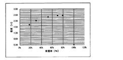
- the torque sensor which concerns on one Example of this invention, it is a graph which shows the relationship between the coverage (horizontal axis) of a magnetic structure, and the sensitivity (vertical axis) of this torque sensor.
- the torque sensor which concerns on one Example of this invention, it is a graph which shows the relationship between the length L / width W (horizontal axis) of the magnetostrictive film pattern of a magnetic structure, and the sensitivity (vertical axis) of a torque sensor.
- the height H 1 of the end portion of the magnetostrictive film in the magnetic structure / the maximum film thickness H (horizontal axis) of the magnetostrictive film and the sensitivity (vertical axis) of the torque sensor is a graph which shows a relationship.
- FIG. 1 is a partial sectional view showing a schematic configuration of a magnetostrictive sensor according to an embodiment of the present invention.
- a magnetostrictive torque sensor (hereinafter simply referred to as “torque sensor”) for detecting torque acting on a base 21 attached to a rotating shaft (not shown) may be used. .) 1 will be described.
- torque sensor for detecting torque acting on a base 21 attached to a rotating shaft (not shown)
- the torque sensor 1 includes a magnetic structure 20 having a magnetostrictive film 2 (magnetostrictive portion) and a detection unit 30 having coils 3 and 4.
- the magnetic structure 20 is formed in a cylindrical shape extending along the axis A.
- the magnetic structure 20 is disposed on the outer peripheral surface of a rotating shaft (not shown).
- FIG. 2 is a diagram showing a schematic configuration of the magnetic structure 20.
- the magnetic structure 20 includes a cylindrical base material 21 that extends along the axis A (that is, extends in the axial direction), and the magnetostrictive film 2. A detailed configuration of the magnetic structure 20 will be described later.
- the magnetostrictive film 2 is provided on the outer peripheral surface 21 s of the cylindrical base material 21.
- the magnetostrictive film 2 has a plurality of magnetostrictive array portions 2a, which will be described in detail later.
- FIG. 3 is a view of the magnetostrictive film 2 formed on the magnetic structure 20 when viewed from a direction orthogonal to the axis A (see FIG. 1).
- the pattern of the magnetostrictive film 2 shown in FIG. 3 is an example.
- the plurality of magnetostrictive array portions 2 a extend in a direction intersecting the axis A when viewed from the direction orthogonal to the axis A.
- the interval between adjacent magnetostrictive array portions 2 a is expressed as an interval (interspace) I.
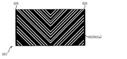
- the magnetostrictive film 2 has two regions 2 b and 2 c arranged in the axial direction of the base material 21. A plurality of magnetostrictive array portions 2a are formed across the two regions 2b and 2c. The magnetostrictive row portion 2a in one region and the magnetostrictive row portion 2a in the other region are provided symmetrically across the center line of the magnetostrictive film 2 in the axial direction. That is, the magnetostrictive array portion 2a of the magnetostrictive film 2 is formed in a V shape when viewed from the direction orthogonal to the axis A (in the state shown in FIG. 3).
- the magnetostrictive string portion 2a in the region 2b of the magnetostrictive film 2 has Either the tension direction or the compression direction force is input to the stretching direction.
- the other force of the tension direction or the compression direction is input to the magnetostriction array portion 2a of the region 2c in the magnetostrictive film 2 in the extending direction.
- the magnetic permeability changes in the magnetostrictive array portion 2a of the regions 2b and 2c of the magnetostrictive film 2.
- the detection unit 30 has two cylindrical coils 3 and 4 and a yoke 5. As shown in FIG. 1, the coils 3 and 4 are disposed so as to surround the magnetic structure 20. In the example of FIG. 1, the coils 3 and 4 are arranged side by side in the axial direction with respect to the magnetic structure 20. Specifically, as shown in FIG. 1, the coil 3 surrounds one region 2 b of the magnetostrictive film 2, and the coil 4 surrounds the other region 2 c of the magnetostrictive film 2. It is arranged against.
- the yoke 5 has a recess for arranging the coils 3 and 4. The coils 3 and 4 are disposed inside the cylindrical yoke 5.
- the coils 3 and 4 generate an alternating magnetic field around the coils 3 and 4 by being connected to the alternating current power source 6 as shown in FIG.
- the coils 3 and 4, the yoke 5, and the base material 21 constitute a magnetic circuit.
- the coils 3 and 4 are also connected to the torque detection circuit 7 as shown in FIG.
- FIG. 20 is a diagram illustrating an example of a configuration of an electronic circuit included in the torque sensor 1.
- the circuit shown in FIG. 20 includes an AC power supply 6 and a torque detection circuit 7.
- the AC power source 6 applies an AC voltage to the coils 3 and 4.
- the torque detection circuit 7 detects the torque generated in the base material 21 by detecting the voltage generated in the coils 3 and 4.
- the torque detection circuit 7 calculates a voltage difference Vout generated in each of the coils 3 and 4 and then calculates a torque generated in the base material 21 based on the difference Vout by an arithmetic circuit (not shown).
- the electronic circuit included in the torque sensor 1 is not limited to the configuration shown in FIG.
- the magnetostrictive array 2a in the regions 2b and 2c of the magnetostrictive film 2 in the torque sensor 1 has a tensile direction or a compression in the extending direction. Direction force is input. Therefore, in the regions 2b and 2c of the magnetostrictive film 2, the change in magnetic permeability generated in the magnetostrictive array portion 2a is different. Such a difference in permeability change is detected as a difference in voltage generated in the coils 3 and 4 in the torque detection circuit 7. Therefore, the torque detection circuit 7 can detect the torsional torque input to the base material 21.
- positioning of each structural member in the torque sensor 1 shown in FIG. 1 is an example.
- the number, arrangement, and the like of the coils 3 and 4 and the yoke 5 are not limited to the configuration shown in FIG. 1 and can be appropriately changed by those skilled in the art.
- the length L / width W of the magnetostrictive array part 2a of the magnetostrictive film 2 shown in FIG. 3 satisfies the following formula (2).
- the magnetostrictive array portion 2a extends in a first direction intersecting the axis A when viewed from the direction orthogonal to the axis A.
- the magnetostrictive array portion 2a extends in a second direction that intersects the first direction when viewed from the direction orthogonal to the axis A.
- the magnetostrictive string portion 2 a has a bent portion Z that is bent at an angle ⁇ in the central portion of the magnetostrictive film 2 in the axial direction of the base material 21.
- the coverage defined by the following formula (1) is 30% or more and 95% or less.
- the magnetostrictive string portion 2 a intersects the axis A from the end X in the axial direction of the magnetostrictive film 2 in the region 2 b of the magnetostrictive film 2 when viewed from the direction orthogonal to the axis A.
- the magnetostrictive film 2 extends toward the central portion in the axial direction (bending portion Z of the magnetostrictive string portion 2a).
- the extending direction of the magnetostrictive string portion 2a in the region 2b of the magnetostrictive film 2 corresponds to the first direction described above.
- the magnetostrictive array portion 2a is viewed in a direction perpendicular to the axis A in a direction that forms an angle ⁇ with the first direction in the region 2c of the magnetostrictive film 2, that is, the center of the magnetostrictive film 2 in the axial direction. From the portion (the curved portion Z of the magnetostrictive array portion 2a) intersects the axis A and extends toward the other end Y in the axial direction of the magnetostrictive film 2. The extending direction of the magnetostrictive string portion 2a in the region 2c of the magnetostrictive film 2 corresponds to the second direction described above.
- FIG. 3 shows an example of the magnetostrictive film 2 in which the magnetostrictive array portion 2a has the curved portion Z.
- the curved portion Z is an intersection of the first portion 2m (the magnetostrictive row portion 2a in the region 2b) and the second portion 2n (the magnetostrictive row portion 2a in the region 2c) of the magnetostrictive row portion 2a. That is, in the magnetostrictive film 2 shown in FIG. 3, one magnetostrictive array portion 2 a includes a first portion 2 m extending from one end X in the axial direction of the magnetostrictive film 2 to the curved portion Z, and a curved portion Z.
- the magnetostrictive film 2 has a second portion 2n extending to the other end Y in the axial direction.
- Coverage Area of the area in contact with the magnetostrictive film 2 on the outer peripheral surface 21s of the base material 21 / Total area (%) of the outer peripheral surface 21s of the base material 21 (1) 30 ⁇ length L / width W ⁇ 120 (2)
- the length L / width W of the magnetostrictive string portion 2a is equal to the length / width of the magnetostrictive string portion 2a in the first portion 2m and the magnetostrictive string portion 2a in the second portion 2n. It is the sum of length / width.
- the length / width of the magnetostriction array portion 2a in the first portion 2m is (distance L 1 from the end X of the magnetostriction array portion 2a shown in FIG. 3 to the curved portion Z) / (magnetostriction array in the first portion 2m). Width of part 2a).
- the length / width of the magnetostriction array portion 2a in the second portion 2n is (distance L 2 from the curved portion Z to the end Y of the magnetostriction array portion 2a shown in FIG. 3) / (magnetostriction array in the second portion 2n. Width of part 2a).
- the torque sensor 1 having good sensitivity can be realized. That is, in the above formula (1), when the coverage is 30% or more, sufficient sensitivity can be obtained in the torque sensor 1.
- the coverage is 95% or less, the shape of the magnetostrictive film 2 is less likely to vary. Therefore, when the coverage is 95% or less, there is no portion in contact between the adjacent magnetostrictive array portions 2a, and thus the torque sensor 1 can obtain sufficient sensitivity.
- the coverage is preferably 50% or more.
- the coverage is more preferably 60% or more.
- the coverage is preferably 93% or less.
- the coverage is more preferably 90% or less.
- the coverage is more preferably 85% or less.
- the torque sensor 1 having good sensitivity can be obtained.
- the torque sensor 1 when the length L / width W is 30 or more, the torque sensor 1 has sufficient sensitivity.
- the magnetostrictive film 2 can be easily manufactured.
- the length L / width W is preferably less than 95.
- the length L / width W is more preferably less than 85.
- the length L / width W is preferably 43 or more.
- the length L / width W is more preferably 53 or more.
- the length L / width W is more preferably 75 or more.
- an angle formed between the first direction and the second direction in the curved portion Z of the magnetostrictive string portion 2a is preferably 60 ° or more and 120 ° or less.
- the angle is more preferably 80 ° or more.
- the angle is preferably 100 ° or less.
- the magnetostriction array portion 2a does not have a curved portion (for example, the magnetostriction array portion 902a of the magnetostrictive film 902 shown in FIG. 12)
- the angle formed between the first portion 2m and the second portion 2n is the same as described above. Within the range, the sensitivity of the torque sensor 1 can be further increased.
- the magnetostriction array portion 2 a has the axis A and the first axis as seen from the direction orthogonal to the axis A of the substrate 21 as shown in FIG. 3.
- the absolute value of the angle ⁇ 1 formed with the direction is preferably 30 ° or more and 60 ° or less (more preferably, the angle ⁇ 1 is ⁇ 45 °).
- the absolute value of the angle ⁇ 2 formed by the base material 21 and the second direction is preferably 30 ° or more and 60 ° or less (more preferably, the angle ⁇ 2 is ⁇ 45 °).
- the magnetostrictive film 2 shown in FIG. 3 further includes a connecting portion 26 that connects the end portions of the adjacent magnetostrictive array portions 2a in the axial direction.
- the connecting portions 26 are respectively provided at both end portions in the axial direction of the magnetostrictive array portion 2a.
- FIGS. 4 to 12 are diagrams showing other examples of the magnetostrictive string portion 2a in the magnetostrictive film 2 of the magnetic structure 20 shown in FIG.
- the magnetostrictive film 102 shown in FIG. 4 differs from the magnetostrictive film 2 shown in FIG. 3 in the angle ⁇ between the first portion 102m and the second portion 102n in the magnetostrictive array portion 102a. More specifically, in the magnetostrictive film 102 shown in FIG. 4, the angle ⁇ is more than 90 ° (and less than 180 °).
- reference numeral 120 denotes a magnetic structure.
- Reference numeral 126 denotes a connecting portion.
- the magnetostrictive film 202 shown in FIG. 5 has a connecting portion 226 that connects the ends of adjacent magnetostrictive row portions 202a in both the axial directions of the magnetostrictive row portion 202a. It is provided at each end.
- the magnetostrictive film 202 is provided with a connecting portion 226 that connects the curved portions Z of adjacent magnetostrictive string portions 202a.
- the strength of the magnetostrictive film 202 including the plurality of magnetostrictive array portions 202a is further increased by providing the connecting portion 226 that connects the curved portions Z of the adjacent magnetostrictive array portions 202a. It has been.
- reference numeral 220 denotes a magnetic structure.
- Reference numeral 202m is a first portion of the magnetostrictive string 202a.
- Reference numeral 202n denotes a second portion of the magnetostrictive string portion 202a.
- the connecting portion 326 that connects the end portions in the axial direction of the adjacent magnetostrictive row portions 2a is a magnetostrictive row portion. Both end portions in the axial direction in 302a and the curved portions Z are connected to each other.
- adjacent magnetostrictive array portions 302a are connected to each other by a connecting portion 326 that connects the central portions in the axial direction in the first portion 302m and the central portions in the axial direction in the second portion 302n. Is further provided.
- the connecting portion 326 that connects the first portions 302m or the second portions 302n in the adjacent magnetostrictive array portions 302a is provided, the strength of the magnetostrictive film 302 is further increased. Has been enhanced.
- reference numeral 320 denotes a magnetic structure.
- the connecting portions 426 that connect the adjacent magnetostrictive string portions 402 a are a plurality of magnetostrictive string portions 402 a. Only a part of them may be connected.
- reference numeral 420 denotes a magnetic structure.
- Reference numeral 402 denotes a magnetostrictive film.
- Reference numeral 402a is a magnetostrictive string portion.
- Reference numeral 402m is a first portion of the magnetostrictive string portion 402a.
- Reference numeral 402n denotes a second portion of the magnetostrictive string portion 402a.
- the magnetostrictive film 502 may not be provided with a connecting portion.
- the magnetostrictive film 602 may have a plurality of magnetostrictive array portions 602a provided only on a part of the outer peripheral surface of the substrate.
- the interval between adjacent magnetostrictive array portions 702a in the magnetostrictive film 702 may not be uniform.
- the width W of the plurality of magnetostrictive array portions 802a in the magnetostrictive film 802 may not be uniform.
- reference numeral 520 denotes a magnetic structure.
- Reference numeral 502a denotes a magnetostrictive string portion.
- Reference numeral 502m is a first portion of the magnetostrictive string portion 502a.
- Reference numeral 502n denotes a second portion in the magnetostrictive string portion 502a.
- reference numeral 626 denotes a connecting portion.
- reference numeral 720 denotes a magnetic structure.
- Reference numeral 726 denotes a connecting portion.
- reference numeral 826 denotes a connecting portion.
- a magnetostrictive film 902 shown in FIG. 12 is one of modifications of the magnetostrictive film 2 shown in FIG.
- the first portion 902m and the second portion 902n are separated by providing a gap 27 instead of the curved portion Z of the magnetostrictive array portion 2a shown in FIG.
- the demagnetizing factor is increased as compared with the configuration shown in FIGS.
- the sensitivity of the torque sensor is slightly lower than that of the magnetostrictive film shown in FIG.
- the length L / width W of the formula (2) is (in the axial direction, the other end portion X from one end X 1 in the first portion 902m distance to 2) / (width of the magnetostrictive column portion 902a in the first portion 902m), or, (in the axial direction, from one end Y 1 of the second portion 902n to the other end Y 2 Distance) / (width of the magnetostrictive string portion 902a in the second portion 2n).
- reference numeral 920 denotes a magnetic structure.
- Reference numeral 926 denotes a connecting portion.
- the magnetostrictive film 1002 shown in FIG. 13 is different from the magnetostrictive film 2 shown in FIG. 3 in the position of the curved portion Z in the axial direction. More specifically, in the magnetostrictive film 2 shown in FIG. 3, the length L 1 of the first portion 2m constituting the magnetostrictive column portion 2a and the length L 2 of the second portion 2n equal. In the magnetostrictive film 2 shown in FIG. 3, the magnetostrictive array portion 2 a has a line-symmetric shape across the center line of the magnetostrictive film 2 in the axial direction. On the other hand, in the magnetostrictive film 1002 shown in FIG. 13, the length of the first portion 1002m and the length of the second portion 1002n are different (in FIG. 13, the length of the first portion 1002m is the second portion 1002n. Is longer than the length of). The ratio of the length of the first portion 1002m and the second portion 1002n is preferably 0.5 or more and 2 or less.
- reference numeral 1020 denotes a magnetic structure.
- Reference numeral 1026 denotes a connecting portion.
- FIG. 14 schematically shows a section of the magnetic structure 20 shown in FIG.
- the cross section shown in FIG. 14 is a cross section obtained by cutting the magnetic structure 20 along a plane orthogonal to the stretching direction in the magnetostrictive array portion 2a. More specifically, the cross section shown in FIG. 14 is obtained when the magnetostrictive array portion 2a is cut along a plane perpendicular to the first direction (the direction from the end portion X of the magnetostrictive film 2 to the curved portion Z in FIG. 2).
- FIG. 4 is a cross section (a cross section cut along a line CC in FIG. 3 in a direction perpendicular to the paper surface).
- the magnetic structure 20 includes a cylindrical base material 21 and a magnetostrictive film 2 provided on the outer peripheral surface 21 s of the base material 21. Note that “M” in FIG. 14 corresponds to “W” in FIG. 3.
- the magnetostrictive film 2 is made of a material containing a magnetic material.
- the magnetic material is preferably a ferromagnetic material.
- the magnetic biomaterial preferably includes at least one metal selected from, for example, Ni, Fe, Co, and Cr. From the viewpoint of obtaining a high magnetic permeability and a high magnetostrictive effect, the magnetic material preferably includes Fe and at least one selected from Ni, Co, and Cr.
- the magnetostrictive film 2 may further include a metal such as Al, Ti, Ge, Mo, Ag, or Cu, or a non-metallic material such as Si, B, S, C, O, or N.
- the content of Fe in the magnetostrictive film 2 is preferably 20% by mass or more and 40% by mass or less from the viewpoint of obtaining higher magnetic permeability and higher magnetostrictive effect.
- the Fe content is more preferably 23% by mass or more.
- the content of Fe is more preferably 26% by mass or more.
- the Fe content is more preferably 36% by mass or less.
- the Fe content is more preferably 33% by mass or less.
- the total content of metals other than Fe (at least one selected from Ni, Co and Cr) is preferably 60% by mass or more and 80% by mass or less.
- the total content of metals other than Fe is more preferably 64% by mass or more.
- the total content of metals other than Fe is more preferably 67% by mass or more.
- the total content of metals other than Fe is more preferably 77% by mass or less.
- the total content of metals other than Fe is more preferably 74% by mass or less.
- the magnetostrictive film 2 contains Fe and Ni
- content of Ni is 60 to 80 mass%.
- the Ni content is more preferably 64% by mass or more.
- the Ni content is more preferably 67% by mass or more.
- the Ni content is more preferably 77% by mass or less.
- the Ni content is more preferably 74% by mass or less.
- the content of S in the magnetostrictive film 2 is preferably 0.03% by mass or more and 0.12% by mass or less.
- the content of S is more preferably 0.04% by mass or more and 0.10% by mass or less.
- the content of S is more preferably 0.05% by mass or more and 0.09% by mass or less.
- the maximum film thickness H of the magnetostrictive film 2 (from the surface where the magnetostrictive film 2 is in contact with the base material 21 (the outer peripheral surface 21s of the base material 21) to the position where the magnetostrictive film 2 protrudes most outward in the radial direction of the base material 21. ) Is 20 ⁇ m or more and 200 ⁇ m or less.
- the maximum film thickness H is preferably 40 ⁇ m or more.
- the maximum film thickness H is more preferably 60 ⁇ m or more.
- the maximum film thickness H is preferably 140 ⁇ m or less.
- the maximum film thickness H is more preferably 100 ⁇ m or less.
- the magnetostrictive array portion 2a of the magnetostrictive film 2 is viewed in a cross-section orthogonal to the extending direction thereof, in a direction orthogonal to the radial direction of the base material 21 (a direction parallel to the outer peripheral surface 21s of the base material 21). It has a part longer than the length of the part by the side of the base material 21 in the magnetostriction row
- the magnetostrictive array portion 2 a has projecting portions 2 e that project from the main body portion formed on the base material 21 to one and the other in the direction orthogonal to the radial direction of the base material 21. Since the magnetostrictive string portion 2a has the protrusion 2e, the surface area of the magnetostrictive string portion 2a is increased.
- the angle ⁇ e formed by the contact surface between the magnetostrictive array portion 2a and the substrate 21 and the protruding direction of the protruding portion 2e is preferably an acute angle (less than 90 °).
- the angle ⁇ e is more preferably greater than 0 ° and not greater than 45 °.
- the angle ⁇ e is more preferably 30 ° or less.
- the magnetostrictive array portion 2a of the magnetostrictive film 2 has the protruding portion 2e as described above, in the cross section shown in FIG. 14, from the outer peripheral surface 21s of the base material 21, the radial direction of the base material 21 (of the magnetostrictive array portion 2a).
- the width M at a predetermined distance in the thickness direction) is longer than the width N of the contact portion 2f between the magnetostrictive film 2 and the outer peripheral surface 21s of the substrate 21.
- the plurality of magnetostrictive row portions 2a in the magnetostrictive film 2 are viewed in a direction perpendicular to the radial direction of the base material 21 when the magnetostrictive row portion 2a is viewed in a cross section perpendicular to the extending direction (the cross section shown in FIG. 14).
- the length of the longest portion (the length M at the position of the predetermined distance, hereinafter referred to as the maximum width dimension M) is larger than the length N of the contact portion 2f between the magnetostrictive film 2 and the outer peripheral surface 21s of the substrate 21.
- the maximum width dimension M is larger than the interval D between adjacent magnetostrictive array portions 2a.
- the interval D between the adjacent magnetostrictive row portions 2a means the interval between the contact portion 2f between the magnetostrictive row portion 2a and the base material 21 and the contact portion 2f between the adjacent magnetostrictive row portion 2a and the base material 21.
- the sensitivity of the torque sensor 1 can be increased by forming the magnetostrictive array portion 2a having the shape as described above. That is, in the magnetostrictive film 2, the maximum width dimension M of the magnetostrictive string portions 2a is larger than the interval D between adjacent magnetostrictive string portions 2a when the magnetostrictive string portions 2a are viewed in a cross section orthogonal to the extending direction. In such a configuration, the interval D between the magnetostrictive array portions 2a is relatively narrow.
- the maximum width dimension M in the magnetostrictive row portion 2a is larger than the length N of the contact portion 2f between the magnetostrictive film 2 and the outer peripheral surface 21s of the substrate 21.
- the above-described configuration increases the sensitivity of the torque sensor 1 without changing the coverage defined by the above formula (1) and the length L / width W defined by the above formula (2). be able to.
- the magnetostrictive row portion 2a has a distance D between the contact portion 2f with the outer peripheral surface 21s of the base material 21 and the contact portion 2f with the outer peripheral surface 21s of the base material 21 in the adjacent magnetostrictive row portion 2a. Is longer than the sum of the length projecting toward the adjacent magnetostrictive row portion 2a and the length projecting portion 2e of the adjacent magnetostrictive row portion 2a toward the magnetostrictive row portion 2a.
- the magnetostrictive row portion 2a has a maximum width dimension M larger than the height (maximum film thickness) H in the thickness direction of the magnetostrictive row portion 2a as seen in the cross section shown in FIG.
- column part 2a is formed in flat shape longer in the direction (direction parallel to the outer peripheral surface 21s of the base material 21) orthogonal to the radial direction of the base material 21 than the thickness direction. Therefore, the surface area of the magnetostrictive string portion 2a can be further increased. Therefore, it is possible to more easily detect a change in magnetic permeability when a force is applied to the magnetostrictive film 2.
- the maximum film thickness H of the magnetostrictive column portion 2a, the height at the end m e of the magnetostrictive column portion 2a (magnetostrictive column portion 2a and the substrate 21 The ratio H 1 / H to the distance from the contact surface to the tip of the protrusion 2 e, that is, the height from the outer peripheral surface 21 s of the substrate 21 to the position of the maximum width dimension M) H 1 is less than 1. . H 1 / H is preferably 0.8 or less. H 1 / H is more preferably 0.5 or less. H 1 / H is more preferably 0.3 or less. Meanwhile, H 1 / H is preferably 0.015 or more.
- the magnetostrictive string portion 2a By forming the magnetostrictive string portion 2a so that H 1 / H is in the above range, the surface area of the magnetostrictive string portion 2a can be further increased. Therefore, it is possible to more easily detect a change in magnetic permeability when a force is applied to the magnetostrictive film 2.
- H 1 / H below 0.5, that is, half the height of the maximum film thickness H of the magnetostrictive column portion 2a, from the outer peripheral surface 21s of the substrate 21 to the position of the maximum width M
- 17, 18, and 19 are each obtained by cutting another example of the magnetic structure in a cross section similar to that in FIG. 2 (cut along a plane orthogonal to the extending direction of the magnetostrictive string portion 2 a). Cross section). 17, 18, and 19, the angle ⁇ e formed between the outer peripheral surface 21 s of the base material 21 and the protruding directions of the protruding portions 2002 e, 3002 e , and 4002 e in the magnetostrictive array portions 2002 a, 3002 a, and 4002 a and the ratio H 1 / H is, if each different from the example shown in FIG. 14 (theta e is 20 °, respectively, 5 °, 3 °, the ratio H 1 / H is 0.5,0.2,0.1) shows the .
- the surface area of the magnetostrictive string portion 5002a is as shown in FIGS. Or smaller than the magnetostrictive rows 2002a, 3002a, 4002a having 19 cross sections. Therefore, the sensitivity of the torque sensor is inferior to that of the magnetostrictive string portions 2002a, 3002a, and 4002a having the cross sections of FIGS.
- the base material 21 is made of a material having a component different from that of the magnetostrictive film 2, for example, a material having a lower magnetic permeability than the magnetostrictive film 2.
- the substrate 21 is preferably made of a magnetic material, and more preferably made of a ferromagnetic material such as Fe, Ni, Co, or Cr.
- the base material 21 may contain a metal such as Al, Ti, Ge, Mo, Ag, or Cu, or a non-metallic material such as Si, B, S, C, O, or N.
- the magnetic structure 20 may further include a resist layer provided on the surface of the magnetostrictive film 2.
- the thickness of the resist layer is preferably 45 ⁇ m or less.
- FIGS. 16A and 16B are views for explaining a method for manufacturing the magnetic structure 20.
- FIG. 16 is a cross-sectional view showing the substrate 21, the magnetostrictive film 2, the resist layer 91, and the like cut along the same plane as FIG. 14 in the manufacturing process of the magnetic structure 20.
- the magnetic structure 20 forms a resist layer 91 having a predetermined pattern on the outer peripheral surface 21 s of the base material 21, and forms the magnetostrictive film 2 on the outer peripheral surface 21 s of the base material 21 provided with the resist layer 91. And a process.
- a method for manufacturing the magnetic structure 20 will be specifically described.
- a resist layer 91 having a predetermined pattern is formed on the outer peripheral surface 21 s of the base material 21.
- the resist layer 91 is used to form the magnetostrictive array portion 2a shown in FIGS. 1, 2, and 3 to 12.
- the resist layer 91 can be formed by a known method such as water transfer or screen printing.
- the film thickness of the resist layer 91 is, for example, 3 ⁇ m or more and 45 ⁇ m or less.
- the angle ⁇ f formed by the outer peripheral surface 21s of the base material 21 and the end portion of the resist layer 91 is an obtuse angle (greater than 90 °) so that the protruding portion 2e is formed in the magnetostrictive array portion 2a. .
- the magnetostrictive film 2 is formed on the surface of the substrate 21 on which the resist layer 91 is provided. At that time, the height H of the magnetostrictive film 2, to form a magnetostrictive layer 2 to be higher than the height H 1 of the resist layer 91.
- the magnetostrictive film 2 can be formed by a known method such as a sputtering method, a CVD method, or a plating method. Next, it is preferable to perform heat treatment at a predetermined temperature (for example, 300 ° C. to 1,000 ° C.) for a predetermined time (for example, 1 minute to 48 hours). Thus, the magnetic structure 20 having the magnetostrictive film 2 shown in FIG. 14 is obtained.
- the magnetostrictive film 2 is formed and heat-treated, whereby the magnetic structure 20 with good sensitivity can be obtained by a simple method. And can be obtained in a short process. Thereby, the manufacturing cost of the magnetic structure 20 can be reduced.
- a bicycle with electric assist for example, a two-wheeled vehicle, a three-wheeled vehicle, or a four-wheeled vehicle
- the torque sensor 1 detects torque generated when the passenger steps on the pedal.
- the driving of the electric motor is controlled based on the torque value detected by the torque sensor 1.
- FIG. 21 is a diagram showing a schematic configuration of the electrically assisted bicycle 10 which is an example of the electrically assisted vehicle of the present invention.
- left and right, front and rear, and top and bottom mean left and right, front and back, and top and bottom, respectively, based on the state in which the passenger 71 is seated on the saddle 34 of the electric assist-assisted bicycle 10 toward the handle 77.
- the electric assist-assisted bicycle 10 includes a frame 12.
- the frame 12 includes a head pipe 14, an upper pipe 16, a front pipe 18, a seat pipe 70, a pair of rear pipes 72, and a pair of lower pipes 74.
- the upper pipe 16 extends rearward and horizontally from the head pipe 14.
- the front pipe 18 extends rearward and obliquely downward from the head pipe 14.
- the seat pipe 70 connects the rear end portion of the upper pipe 16 and the rear end portion of the front pipe 18.
- the pair of rear pipes 72 extend obliquely rearward and downward from the connection portion between the upper pipe 16 and the seat pipe 70.
- the pair of lower pipes 74 extends in the horizontal direction rearward from the connection portion between the front pipe 18 and the seat pipe 70.
- the rear end portions of the pair of rear pipes 72 and the rear end portions of the pair of lower pipes 74 are connected to each other.
- a steering shaft 76 for changing the traveling direction of the vehicle is provided along the head pipe 14.
- the steering shaft 76 is rotatable within the head pipe 14.
- a handle 77 is attached to the upper end of the steering shaft 76.
- a pair of left and right front forks 80 are attached to the lower end of the steering shaft 76.
- a front wheel 82 is attached to the lower end of the front fork 80.
- the front wheel 82 is rotatable about the central axis of the front wheel 82 supported by the front fork 80.
- a saddle 34 is provided at the upper end of the seat pipe 70.
- a cargo bed 36 is fixed to the seat pipe 70 so as to extend rearward.
- a motor drive unit 38 is disposed at the connection between the front pipe 18 and the seat pipe 70.
- FIG. 22 shows a schematic configuration of the motor drive unit 38 of the bicycle 10 with electric assist.
- the motor drive unit 38 includes the torque sensor 1 according to the above embodiment. More specifically, as shown in FIG. 22, the motor drive unit 38 includes a crankshaft 40, a drive sprocket 42, a crank angle sensor 44 and a torque sensor 1, an electric motor 48, and a controller 50.
- the motor drive unit 38 may be configured to be attachable to a bicycle that is not an electrically assisted bicycle, or may be configured to be replaceable with an existing motor-assisted bicycle motor drive unit.
- a pedal 54 is attached to the crankshaft 40 via a crank 52.
- a drive sprocket 42 (see FIG. 22) is attached to the outer peripheral surface of the crankshaft 40.
- the drive sprocket 42 is connected to a rear wheel sprocket 58 via an endless chain 56.
- a rear wheel 62 is attached to the rear wheel sprocket 58 via a rotating shaft 60. The rear wheel 62 can rotate around the rotation shaft 60.
- crank angle sensor 44 and the torque sensor 1 are disposed in the vicinity of the crankshaft 40.
- Crank angle sensor 44 detects the crank angle theta c is the rotation angle of the crankshaft 40 which is rotated by the operation of the pedal 54.
- the torque sensor 1 detects a crank torque ⁇ that is a torque applied to the crankshaft 40.
- the electric motor 48 generates auxiliary driving force applied to the driving sprocket 42.
- the controller 50 includes a CPU 64 and a memory 66.
- the CPU 64 performs necessary calculations and controls the operation of the electric motor 48 and the electric assist-assisted bicycle 10.
- the memory 66 that is a storage means is composed of, for example, an EEPROM, and stores programs, data, calculation data, and the like for controlling the operation of the bicycle 10 with electric assistance.
- the memory 66 stores assist patterns.
- CPU64 on the basis of the crank angle theta c and crank torque tau, controls the auxiliary driving force generated by the electric motor 48.
- the bicycle 10 with an electric assist includes the torque sensor 1 according to the above-described embodiment that can detect torque with high sensitivity and high accuracy, and thus can stably travel.
- the torque sensor 1 includes a cylindrical base material 21 extending along the axis A and a magnetostrictive film 2 formed on the outer peripheral surface 21 s of the base material 21.
- the magnetostrictive film 2 has a plurality of magnetostrictive row portions 2a extending in a row. At least a portion of the plurality of magnetostrictive row portions 2a is the longest portion in the direction parallel to the outer peripheral surface 21s of the base material 21 when the magnetostrictive row portion 2a including the portion is viewed in a cross section orthogonal to the extending direction.
- the magnetostrictive row portion 2a has a length M that is the longest in the direction parallel to the outer peripheral surface 21s of the base member 21 when viewed in a cross section orthogonal to the extending direction. Is larger than the interval D. Therefore, the interval D between the magnetostrictive string portions 2a is relatively narrow. In such a configuration in which the interval D between the adjacent magnetostrictive row portions 2a is narrow, the length M of the longest portion is set to be longer than the length N of the contact portion 2f between the magnetostrictive row portion 2a and the outer peripheral surface 21s of the substrate 21. By increasing the size, the surface area of the magnetostrictive array portion 2a can be increased. Therefore, it is possible to easily detect a change in magnetic permeability when a force is applied to the magnetostrictive film 2. Thereby, the sensitivity of the torque sensor 1 can be improved while the magnetostrictive film 2 is limited in size.
- the at least a part of the plurality of magnetostrictive array portions 2a includes the magnetostrictive array portion 2a having a length M of the longest portion when the magnetostrictive array portion 2a including the part is viewed in a cross section orthogonal to the extending direction. It is larger than the maximum film thickness H.
- the base plate 21 being located more than the thickness direction of the magnetostrictive row portion 2a when the magnetostrictive row portion 2a including the part is viewed in a cross section perpendicular to the extending direction. It is formed in a flat shape that is long in a direction parallel to the outer peripheral surface 21s. Therefore, the surface area of the magnetostrictive string portion 2a can be further increased. Therefore, it is possible to more easily detect a change in magnetic permeability when a force is applied to the magnetostrictive film 2. Thereby, the sensitivity of the torque sensor 1 can be further improved while the magnetostrictive film 2 is limited in size.
- the at least part of the plurality of magnetostrictive array portions 2a is such that the maximum film thickness H of the magnetostrictive array portion 2a is equal to that of the substrate 21 when the magnetostrictive array portion 2a including the part is viewed in a cross section orthogonal to the extending direction. It is larger than the height H 1 in the thickness direction from the outer peripheral surface 21 s to the longest portion of the base material 21.
- the magnetostrictive array parts 2a is seen from the contact part 2f with the outer peripheral surface 21s of the base member 21 when the magnetostrictive array part 2a including the part is viewed in a cross section orthogonal to the extending direction. Also, a portion having a large width dimension can be formed. Therefore, the surface area of the magnetostrictive row portion can be increased as compared with the magnetostrictive row portion that does not have a portion having a width dimension larger than that of the contact portion 2f with the outer peripheral surface 21s of the base material 21. Therefore, it is possible to easily detect a change in magnetic permeability when a force is applied to the magnetostrictive film 2. Thereby, the sensitivity of the torque sensor 1 can be improved while the magnetostrictive film 2 is limited in size.
- the magnetostrictive array part 2a is most viewed in a direction parallel to the outer peripheral surface 21s of the base material 21 when the magnetostrictive array part 2a including the part is viewed in a cross section orthogonal to the extending direction.
- the long portion can be formed in a wider range in the thickness direction of the magnetostrictive string portion 2a. Therefore, the surface area of the magnetostrictive array portion can be further increased. Therefore, it is possible to more easily detect a change in magnetic permeability when a force is applied to the magnetostrictive film 2.
- the at least part of the plurality of magnetostrictive array parts 2a includes the contact part 2f, the adjacent magnetostrictive array part 2a and the base material when the magnetostrictive array part 2a including the part is viewed in a cross section orthogonal to the extending direction.
- the distance D between the contact portion 2 f and the outer surface 21 s of the base 21 is the longest portion facing the magnetostriction array portion 2 a adjacent to the contact portion 2 f.
- the longest portion of the adjacent magnetostriction array portion 2a protrudes toward the magnetostriction array portion 2a with respect to the contact portion 2f between the adjacent magnetostriction array portion 2a and the substrate 21. Greater than sum.
- the magnetostrictive film 2 has a connecting portion 26 that connects a plurality of magnetostrictive array portions 2a. This makes it difficult for the magnetostrictive array portion 2a to peel off from the substrate 21. Therefore, the strength of the magnetostrictive film 2 can be improved.
- the torque sensor 1 further includes coils 3 and 4 arranged so as to surround the magnetostrictive film 2. Thereby, the change in the magnetic permeability generated in the magnetostrictive film 2 can be detected by the change in the impedance of the coils 3 and 4.
- a plurality of coils 3 and 4 are arranged along the axis A.
- the change of the magnetic permeability in the magnetostrictive film 2 can be detected more reliably by the plurality of coils 3 and 4. Therefore, the detection accuracy of the torque sensor 1 can be improved.
- the configuration of this embodiment is applied to the torque sensor 1 as an example of a magnetostrictive sensor.
- the configuration of the present embodiment may be applied to other sensors such as a load sensor as long as the sensor has a magnetostrictive film.
- the configuration of the present embodiment may be applied not only to a torque sensor used for a bicycle with an electric assist but also to sensors for other uses.
- the base material 21 is cylindrical.
- the base material 21 may have any cross-sectional shape as long as it is cylindrical or columnar.
- the magnetostrictive row portion 2a of the magnetostrictive film 2 extends in a row.
- at least a part of the plurality of island-shaped magnetostrictive portions formed in an island shape may be connected and formed in a row shape.
- the plurality of magnetostrictive array portions 2a may not be parallel as long as they do not contact each other.
- the plurality of magnetostrictive array portions 2a in the magnetostrictive film 2 have the same cross section as the cross section shown in FIG.
- the cross section of the magnetostrictive row portion 2a may be different in a part of the extending direction of the magnetostrictive row portion 2a.
- the plurality of magnetostrictive array portions 2a may not all have the same cross-sectional shape.
- the magnetostrictive array portion 2a has the protruding portions 2e protruding in one and the other in the direction parallel to the outer peripheral surface 21s of the base material 21 when viewed in a cross section orthogonal to the extending direction.
- the magnetostrictive array portion 2a may have a protruding portion that protrudes in one or the other direction parallel to the outer peripheral surface 21s of the base material 21.
- the magnetostrictive row portion 2a has a longest length M in the direction parallel to the outer peripheral surface 21s of the base material 21 as viewed in a cross section perpendicular to the extending direction, and the maximum film of the magnetostrictive row portion 2a. Greater than thickness H. However, in the magnetostrictive array portion 2a, the length M of the longest portion may be equal to or less than the maximum film thickness H.
- the magnetostrictive array portion 2a has the longest half of the maximum film thickness H of the magnetostrictive array portion 2a from the outer peripheral surface 21s of the base material 21 to the base material 21 when viewed in a cross section orthogonal to the extending direction. wherein is the thickness direction of the height H 1 or more to the portion.
- magnetostrictive column section 2a half of the maximum thickness M may be smaller than the height H 1.
- Example 1 In the manufacturing method shown in FIG. 16, the magnetic structure 20 in which the magnetostrictive array portion 2a shown in FIG. 3 and the magnetostrictive film 2 having the cross section shown in FIG. 14 were formed by plating.
- Plating was performed with a known Ni—Fe alloy bath (watt bath) using nickel sulfate, nickel chloride, iron (II) sulfate, boric acid or the like.
- the plating conditions were pH 3, bath temperature 55 ° C., current density 5-20 A / dm 2 .
- the uniformity of the film thickness of the obtained plating film (magnetostrictive film 2) was ensured by performing the plating while rotating the base material 21 in the circumferential direction at 3 rotations / minute.
- the obtained magnetostrictive film 2 was heat-treated at 500 ° C. for 1 hour in a nitrogen atmosphere.
- the magnetic structure 20 obtained by the above-described method has a maximum film thickness H of 85 ⁇ m, a width M of 460 ⁇ m, and a length N of the contact surface with the substrate 21 of 260 ⁇ m in the cross section (FIG. 14) of the magnetostrictive array portion 2a.
- the coverage is 17%, 30%, 52%, 70%, 79% (FIG. 23), and the length L / width W of the magnetostrictive array portion 2a is 12, 25, 32, 36, 43, 54, 64, 75, 84, 95, 120 (FIG. 24).
- the angle ⁇ (see FIG. 3) formed by the first direction and the second direction was 90 °. As shown in FIG.
- the angle ⁇ 1 formed by the axis A of the base material 21 and the first direction was 45 °.
- the angle ⁇ 2 formed between the axis A of the base material 21 and the second direction was 45 °.
- the interval I between the adjacent magnetostrictive array portions 2a was 200 ⁇ m. Note that the thickness of the resist layer 91 used for manufacturing the magnetostrictive film 2 was 20 ⁇ m.
- the produced magnetostrictive film 2 was an Fe—Ni alloy.
- the Fe concentration in the magnetostrictive film 2 was 30% by mass, and the Ni concentration was 70% by mass.
- the material of the base material 21 was SCM435 (JIS G4053).
- a torque sensor 1 having the configuration of FIG. 1 was manufactured using the magnetic structure 20 obtained in this example.
- each of the resistors R1 and R2 is a resistor having a resistance value of 15 ⁇ .
- Coils C1 and C2 are each configured by winding a copper wire with an insulating film having a diameter of 0.2 mm 124 times.
- FIG. 23 is a graph showing the relationship between the coverage (horizontal axis) of the magnetic structure 20 and the sensitivity (vertical axis) of the torque sensor 1 in the torque sensor 1 according to this example. According to FIG. 23, it can be understood that the sensitivity is good when the coverage is 30% or more and 95% or less.
- FIG. 24 shows the relationship (coverage ratio) between the length L / width W (horizontal axis) of the magnetostrictive film pattern 2a of the magnetic structure 20 and the sensitivity (vertical axis) of the torque sensor 1 in the torque sensor 1 according to this example. : 70%). According to FIG. 24, it can be understood that when the length L / width W is less than 30, the sensitivity greatly decreases.
- FIG. 25 shows the height H 1 of the end of the magnetostrictive film 2 in the magnetic structure 20 / the maximum film thickness H (horizontal axis) of the magnetostrictive film 2 and the sensitivity of the torque sensor 1 in the torque sensor 1 according to the present embodiment. It is a graph which shows the relationship with (vertical axis).
- H 1 / H are 0.09 (angle ⁇ e : 2 °), 0.12 (angle ⁇ e : 3 °), 0.24 (angle ⁇ e : 5 °), and 0.53 (angle ⁇ e : 15 °))
- H 1 / H are 0.09 (angle ⁇ e : 2 °), 0.12 (angle ⁇ e : 3 °), 0.24 (angle ⁇ e : 5 °), and 0.53 (angle ⁇ e : 15 °)
- Example 2 The magnetostrictive film 2 has the cross section shown in FIG. 14 and the magnetostrictive string portion shown in FIGS. 5 to 11 and 13 in the same manner as in Example 1 except that the magnetostrictive film 2 has the patterns shown in FIGS. Each structure was obtained.
- the torque sensor provided with the magnetic structure according to the present example had the same sensitivity as the torque sensor 1 according to the first example.
- Example 3 A magnetostrictive array portion shown in FIG. 12 and a magnetic structure having a cross section shown in FIG. 14 were obtained in the same manner as in Example 1 except that the magnetostrictive film 2 was changed to the pattern shown in FIG.
- the torque sensor provided with the magnetic structure according to this example had good sensitivity although the sensitivity was slightly inferior to that of the torque sensor 1 according to example 1.
- Example 4 The magnetostrictive string 2a shown in FIG. 3 and FIG. 15 are the same as in Example 1 except that the thickness of the resist layer 91 for forming the magnetostrictive film 2 is 50 ⁇ m and the thickness of the magnetostrictive film 2 is 45 ⁇ m.
- the present invention can be used for a magnetostrictive sensor used in, for example, a bicycle with an electric assist.
Landscapes
- Physics & Mathematics (AREA)
- Electromagnetism (AREA)
- General Physics & Mathematics (AREA)
- Engineering & Computer Science (AREA)
- Chemical & Material Sciences (AREA)
- Combustion & Propulsion (AREA)
- Transportation (AREA)
- Mechanical Engineering (AREA)
- Power Steering Mechanism (AREA)
- Force Measurement Appropriate To Specific Purposes (AREA)
- Measuring Magnetic Variables (AREA)
Abstract
L'invention concerne un capteur magnétostrictif pourvu d'une unité magnétostrictive comprenant de multiples unités en rangée magnétostrictives, dans lequel est obtenue une configuration qui permet d'améliorer la sensibilité même avec les restrictions de dimensions en présence imposées à l'unité magnétostrictive. Un capteur de couple (1) est pourvu d'un film magnétostrictif (2) formé sur la surface périphérique extérieure (21s) d'un substrat (21). Le film magnétostrictif (2) comprend de multiples unités en rangée magnétostrictives (2a) qui s'étendent dans une rangée. Pour au moins une partie des unités en rangée magnétostrictives (2a), en observant les unités en rangée magnétostrictives (2a), y compris ladite partie de celles-ci, dans une section transversale perpendiculaire au sens de leur projection, la longueur de la portion la plus longue dans la direction parallèle à la surface périphérique extérieure (21s) du substrat (21) est supérieure à la longueur de la portion de contact (2f) entre la surface périphérique extérieure (21s) du substrat (21) et les unités en rangée magnétostrictives (2a), y compris ladite partie de celles-ci, et est supérieure à la distance (D) entre la portion de contact (2f) précitée et la portion de contact (2f) entre la surface périphérique extérieure (21s) du substrat (21) et une unité en rangée magnétostrictive (2a) adjacente à l'unité en rangée magnétostrictive (2a) précitée.
Priority Applications (3)
| Application Number | Priority Date | Filing Date | Title |
|---|---|---|---|
| EP16814456.6A EP3315933B1 (fr) | 2015-06-23 | 2016-06-23 | Capteur magnétostrictif, structure magnétique et son procédé de production, unité d'entraînement motorisé pourvue d'un capteur magnétostrictif, et bicyclette assistée à moteur |
| JP2017524979A JP6373497B2 (ja) | 2015-06-23 | 2016-06-23 | 磁歪式センサ、磁性構造体およびその製造方法、ならびに、磁歪式センサを備えたモータ駆動ユニットおよび電動アシスト付き自転車 |
| US15/853,119 US10184847B2 (en) | 2015-06-23 | 2017-12-22 | Magnetostrictive sensor, magnetic structure and production method thereof, motor drive device provided with magnetostrictive sensor, and motor assisted bicycle |
Applications Claiming Priority (4)
| Application Number | Priority Date | Filing Date | Title |
|---|---|---|---|
| JP2015125842 | 2015-06-23 | ||
| JP2015125843 | 2015-06-23 | ||
| JP2015-125843 | 2015-06-23 | ||
| JP2015-125842 | 2015-06-23 |
Related Child Applications (1)
| Application Number | Title | Priority Date | Filing Date |
|---|---|---|---|
| US15/853,119 Continuation-In-Part US10184847B2 (en) | 2015-06-23 | 2017-12-22 | Magnetostrictive sensor, magnetic structure and production method thereof, motor drive device provided with magnetostrictive sensor, and motor assisted bicycle |
Publications (1)
| Publication Number | Publication Date |
|---|---|
| WO2016208687A1 true WO2016208687A1 (fr) | 2016-12-29 |
Family
ID=57585082
Family Applications (2)
| Application Number | Title | Priority Date | Filing Date |
|---|---|---|---|
| PCT/JP2016/068720 Ceased WO2016208688A1 (fr) | 2015-06-23 | 2016-06-23 | Capteur magnétostrictif, structure magnétique et son procédé de production, unité de moteur d'entrainement comprenant le capteur magnétostrictif, et vélo assisté par moteur |
| PCT/JP2016/068719 Ceased WO2016208687A1 (fr) | 2015-06-23 | 2016-06-23 | Capteur magnétostrictif, structure magnétique et son procédé de production, unité d'entraînement motorisé pourvue d'un capteur magnétostrictif, et bicyclette assistée à moteur |
Family Applications Before (1)
| Application Number | Title | Priority Date | Filing Date |
|---|---|---|---|
| PCT/JP2016/068720 Ceased WO2016208688A1 (fr) | 2015-06-23 | 2016-06-23 | Capteur magnétostrictif, structure magnétique et son procédé de production, unité de moteur d'entrainement comprenant le capteur magnétostrictif, et vélo assisté par moteur |
Country Status (4)
| Country | Link |
|---|---|
| US (2) | US10502646B2 (fr) |
| EP (2) | EP3315933B1 (fr) |
| JP (3) | JP6698082B2 (fr) |
| WO (2) | WO2016208688A1 (fr) |
Cited By (4)
| Publication number | Priority date | Publication date | Assignee | Title |
|---|---|---|---|---|
| CN108791681A (zh) * | 2017-05-05 | 2018-11-13 | 捷安特电动车(昆山)有限公司 | 一种测量中轴双边力矩、位置角度、转速及功率的装置 |
| CN108801297A (zh) * | 2017-05-05 | 2018-11-13 | 捷安特电动车(昆山)有限公司 | 一种检测中轴双边力矩、位置角度、转速及功率的装置 |
| JP2022023720A (ja) * | 2020-07-27 | 2022-02-08 | 国立大学法人東北大学 | センサユニットおよびセンサ |
| JP2022049143A (ja) * | 2020-09-16 | 2022-03-29 | 日本精工株式会社 | 自転車 |
Families Citing this family (10)
| Publication number | Priority date | Publication date | Assignee | Title |
|---|---|---|---|---|
| JP6698082B2 (ja) * | 2015-06-23 | 2020-05-27 | ヤマハ発動機株式会社 | 磁歪式センサ、磁性構造体およびその製造方法、ならびに、磁歪式センサを備えたモータ駆動ユニットおよび電動アシスト付き自転車 |
| JP6661502B2 (ja) * | 2016-09-23 | 2020-03-11 | 本田技研工業株式会社 | 磁歪式トルクセンサ、及び磁歪式トルクセンサの製造方法 |
| JP7149325B2 (ja) * | 2017-05-05 | 2022-10-06 | 捷安特電動車(昆山)有限公司 | 乗物の運転パラメータの検出装置 |
| CN108839751B (zh) * | 2018-05-23 | 2024-03-22 | 铂金橙智能科技(太仓)有限公司 | 同轴中置驱动电机系统及助力车 |
| CN110190211B (zh) | 2018-12-29 | 2020-03-31 | 比亚迪股份有限公司 | 电池托盘、动力电池包及车辆 |
| CN111384328A (zh) | 2018-12-29 | 2020-07-07 | 比亚迪股份有限公司 | 电池托盘、动力电池包及车辆 |
| US12230820B2 (en) | 2019-01-09 | 2025-02-18 | Byd Company Limited | Power battery pack and electric vehicle |
| JP7357570B2 (ja) * | 2020-03-03 | 2023-10-06 | 株式会社プロテリアル | 磁歪式トルクセンサの検出回路及び検出方法 |
| DE102020214282A1 (de) * | 2020-11-13 | 2022-05-19 | Zf Friedrichshafen Ag | Verfahren zum Herstellen eines Verformungskörpers zum Messen einer Kraft und/oder eines Drehmoments für ein Wankstabilisierungssystem für ein Fahrzeug und Verformungskörper |
| TWI866777B (zh) * | 2024-02-07 | 2024-12-11 | 達方電子股份有限公司 | 自行車中軸 |
Citations (6)
| Publication number | Priority date | Publication date | Assignee | Title |
|---|---|---|---|---|
| JPH032638A (ja) * | 1989-05-31 | 1991-01-09 | Mitsubishi Electric Corp | 歪検出器 |
| JPH0354429A (ja) * | 1989-06-21 | 1991-03-08 | Eaton Corp | 磁気ひずみセンサおよびその製造方法 |
| JPH04329325A (ja) * | 1991-04-30 | 1992-11-18 | Nissan Motor Co Ltd | トルク検出装置 |
| JPH0572064A (ja) * | 1991-07-12 | 1993-03-23 | Nissan Motor Co Ltd | 被測定軸,トルク検出装置および被測定軸の製造方法 |
| JP2004184189A (ja) * | 2002-12-02 | 2004-07-02 | Yamaha Motor Co Ltd | 磁歪式トルクセンサ |
| JP2004264188A (ja) * | 2003-03-03 | 2004-09-24 | Moric Co Ltd | 磁歪トルクセンサ |
Family Cites Families (22)
| Publication number | Priority date | Publication date | Assignee | Title |
|---|---|---|---|---|
| JPS60254679A (ja) * | 1984-05-30 | 1985-12-16 | Nissan Motor Co Ltd | トルク検出装置 |
| DE3509552A1 (de) * | 1985-03-16 | 1986-09-18 | Vacuumschmelze Gmbh, 6450 Hanau | Ferromagnetische folie fuer einen drehmomentsensor |
| US4823620A (en) | 1986-02-10 | 1989-04-25 | Nissan Motor Company, Ltd. | Magnetostrictive device for measuring torsional torque |
| GB2210460B (en) * | 1987-07-29 | 1991-08-21 | Nissan Motor | Magnetostrictive stress measurement apparatus |
| US4852411A (en) * | 1988-12-21 | 1989-08-01 | Eaton Corporation | Torque sensor |
| US5313845A (en) * | 1989-05-31 | 1994-05-24 | Mitsubishi Denki Kabushiki Kaisha | Strain detector |
| JP2800347B2 (ja) | 1990-02-07 | 1998-09-21 | 株式会社豊田自動織機製作所 | 磁歪式トルクセンサ |
| EP0502721B1 (fr) | 1991-03-04 | 1995-12-27 | Matsushita Electric Industrial Co., Ltd. | Détecteur de couple de rotation sans contact |
| US5280729A (en) | 1991-04-30 | 1994-01-25 | Nissan Motor Co., Ltd. | Magnetostrictive torque detecting apparatus |
| JP3114455B2 (ja) * | 1993-02-02 | 2000-12-04 | 三菱マテリアル株式会社 | 磁歪式トルク検出部を有するシャフトおよびその製造方法 |
| US5585574A (en) | 1993-02-02 | 1996-12-17 | Mitsubishi Materials Corporation | Shaft having a magnetostrictive torque sensor and a method for making same |
| JP3018812B2 (ja) * | 1993-02-12 | 2000-03-13 | 三菱マテリアル株式会社 | 磁歪式トルク検出部を有するシャフトの製造方法 |
| JPH098378A (ja) * | 1995-06-14 | 1997-01-10 | Alps Electric Co Ltd | 磁歪素子 |
| JPH11344394A (ja) * | 1998-05-29 | 1999-12-14 | Toyota Autom Loom Works Ltd | トルクセンサ |
| JP2004340783A (ja) * | 2003-05-16 | 2004-12-02 | Ntn Corp | トルク検出装置 |
| US7564152B1 (en) * | 2004-02-12 | 2009-07-21 | The United States Of America As Represented By The Secretary Of The Navy | High magnetostriction of positive magnetostrictive materials under tensile load |
| US7401531B2 (en) * | 2005-09-23 | 2008-07-22 | Continental Automotive Systems Us, Inc. | Fabrication of a magnetoelastic torque sensor |
| JP4932206B2 (ja) | 2005-09-27 | 2012-05-16 | 本田技研工業株式会社 | 磁歪式トルクセンサの製造方法 |
| JP4936969B2 (ja) | 2007-04-17 | 2012-05-23 | 株式会社東芝 | 磁歪式トルクセンサシャフトの製造装置 |
| JP6698082B2 (ja) * | 2015-06-23 | 2020-05-27 | ヤマハ発動機株式会社 | 磁歪式センサ、磁性構造体およびその製造方法、ならびに、磁歪式センサを備えたモータ駆動ユニットおよび電動アシスト付き自転車 |
| EP3343191B1 (fr) * | 2015-10-01 | 2021-08-25 | Yamaha Hatsudoki Kabushiki Kaisha | Capteur magnétostrictif |
| JP6413027B2 (ja) * | 2015-10-01 | 2018-10-24 | ヤマハ発動機株式会社 | 磁歪式トルクセンサ |
-
2016
- 2016-06-23 JP JP2017524980A patent/JP6698082B2/ja active Active
- 2016-06-23 WO PCT/JP2016/068720 patent/WO2016208688A1/fr not_active Ceased
- 2016-06-23 WO PCT/JP2016/068719 patent/WO2016208687A1/fr not_active Ceased
- 2016-06-23 JP JP2017524979A patent/JP6373497B2/ja active Active
- 2016-06-23 EP EP16814456.6A patent/EP3315933B1/fr active Active
- 2016-06-23 EP EP16814457.4A patent/EP3315934B1/fr active Active
-
2017
- 2017-12-22 US US15/852,700 patent/US10502646B2/en active Active
- 2017-12-22 US US15/853,119 patent/US10184847B2/en active Active
-
2019
- 2019-01-18 JP JP2019007272A patent/JP2019056716A/ja not_active Withdrawn
Patent Citations (6)
| Publication number | Priority date | Publication date | Assignee | Title |
|---|---|---|---|---|
| JPH032638A (ja) * | 1989-05-31 | 1991-01-09 | Mitsubishi Electric Corp | 歪検出器 |
| JPH0354429A (ja) * | 1989-06-21 | 1991-03-08 | Eaton Corp | 磁気ひずみセンサおよびその製造方法 |
| JPH04329325A (ja) * | 1991-04-30 | 1992-11-18 | Nissan Motor Co Ltd | トルク検出装置 |
| JPH0572064A (ja) * | 1991-07-12 | 1993-03-23 | Nissan Motor Co Ltd | 被測定軸,トルク検出装置および被測定軸の製造方法 |
| JP2004184189A (ja) * | 2002-12-02 | 2004-07-02 | Yamaha Motor Co Ltd | 磁歪式トルクセンサ |
| JP2004264188A (ja) * | 2003-03-03 | 2004-09-24 | Moric Co Ltd | 磁歪トルクセンサ |
Non-Patent Citations (1)
| Title |
|---|
| See also references of EP3315933A4 * |
Cited By (5)
| Publication number | Priority date | Publication date | Assignee | Title |
|---|---|---|---|---|
| CN108791681A (zh) * | 2017-05-05 | 2018-11-13 | 捷安特电动车(昆山)有限公司 | 一种测量中轴双边力矩、位置角度、转速及功率的装置 |
| CN108801297A (zh) * | 2017-05-05 | 2018-11-13 | 捷安特电动车(昆山)有限公司 | 一种检测中轴双边力矩、位置角度、转速及功率的装置 |
| JP2022023720A (ja) * | 2020-07-27 | 2022-02-08 | 国立大学法人東北大学 | センサユニットおよびセンサ |
| JP2022049143A (ja) * | 2020-09-16 | 2022-03-29 | 日本精工株式会社 | 自転車 |
| JP7567307B2 (ja) | 2020-09-16 | 2024-10-16 | 日本精工株式会社 | 自転車 |
Also Published As
| Publication number | Publication date |
|---|---|
| EP3315934B1 (fr) | 2020-01-15 |
| US20180120177A1 (en) | 2018-05-03 |
| JP6698082B2 (ja) | 2020-05-27 |
| EP3315934A1 (fr) | 2018-05-02 |
| US20180120178A1 (en) | 2018-05-03 |
| US10502646B2 (en) | 2019-12-10 |
| JP2019056716A (ja) | 2019-04-11 |
| US10184847B2 (en) | 2019-01-22 |
| WO2016208688A1 (fr) | 2016-12-29 |
| JPWO2016208687A1 (ja) | 2018-04-12 |
| JP6373497B2 (ja) | 2018-08-15 |
| EP3315933A4 (fr) | 2018-06-20 |
| EP3315933B1 (fr) | 2019-10-30 |
| JPWO2016208688A1 (ja) | 2018-04-05 |
| EP3315933A1 (fr) | 2018-05-02 |
| EP3315934A4 (fr) | 2018-06-20 |
Similar Documents
| Publication | Publication Date | Title |
|---|---|---|
| JP6373497B2 (ja) | 磁歪式センサ、磁性構造体およびその製造方法、ならびに、磁歪式センサを備えたモータ駆動ユニットおよび電動アシスト付き自転車 | |
| CN1940515B (zh) | 磁致伸缩式转矩传感器 | |
| CN1952637A (zh) | 磁致伸缩扭矩传感器以及使用该传感器的电动转向设备 | |
| JP6296155B2 (ja) | 異方性磁気抵抗素子、磁気センサおよび電流センサ | |
| US10901049B2 (en) | Magnetic sensor and method for manufacturing said magnetic sensor | |
| JP2001133337A (ja) | 磁歪式トルクセンサ及び磁歪式トルクセンサを搭載した電動パワーステアリング装置 | |
| US8011256B2 (en) | Magnetostrictive torque sensor and method of manufacturing same | |
| JP2003142755A (ja) | 磁気抵抗センサ及びその製造方法 | |
| JP2011506958A (ja) | 薄膜フラックスゲートセンサー | |
| CN111033779B (zh) | 交换耦合膜以及使用该交换耦合膜的磁阻效应元件及磁检测装置 | |
| JP5195845B2 (ja) | 磁気センサ及び磁場強度測定方法 | |
| JP2000193407A (ja) | 磁気式位置検出装置 | |
| JP2009192429A (ja) | 磁気センサ及び磁場強度測定方法 | |
| JP6525314B2 (ja) | 磁界検出装置 | |
| JP7567307B2 (ja) | 自転車 | |
| JP2004538467A (ja) | 磁界検知装置 | |
| JP4638713B2 (ja) | センサ用コイル及びそれを用いた磁気センサ | |
| JP2012198038A (ja) | 磁性体部材とその製造方法 | |
| JP2009210325A (ja) | 磁歪式トルクセンサおよび車両用操舵装置 | |
| WO2015182643A1 (fr) | Élément de réluctance, capteur magnétique et capteur de courant | |
| JP6569824B2 (ja) | 磁気抵抗素子、および磁気センサ | |
| JP2006300540A (ja) | 薄膜磁気センサ | |
| JP5927648B2 (ja) | 磁気シールド構造体、電流センサ及び磁気シールド構造体の製造方法 | |
| JP2008256662A (ja) | 磁歪式トルクセンサの製造方法 | |
| KR101306294B1 (ko) | Cnt 압력센서 제조방법 |
Legal Events
| Date | Code | Title | Description |
|---|---|---|---|
| 121 | Ep: the epo has been informed by wipo that ep was designated in this application |
Ref document number: 16814456 Country of ref document: EP Kind code of ref document: A1 |
|
| ENP | Entry into the national phase |
Ref document number: 2017524979 Country of ref document: JP Kind code of ref document: A |
|
| NENP | Non-entry into the national phase |
Ref country code: DE |
|
| WWE | Wipo information: entry into national phase |
Ref document number: 2016814456 Country of ref document: EP |