EP3316444B1 - Système de facturation à contacts compressibles - Google Patents
Système de facturation à contacts compressibles Download PDFInfo
- Publication number
- EP3316444B1 EP3316444B1 EP17195019.9A EP17195019A EP3316444B1 EP 3316444 B1 EP3316444 B1 EP 3316444B1 EP 17195019 A EP17195019 A EP 17195019A EP 3316444 B1 EP3316444 B1 EP 3316444B1
- Authority
- EP
- European Patent Office
- Prior art keywords
- charging
- conductors
- conductor
- contact pad
- contact
- Prior art date
- Legal status (The legal status is an assumption and is not a legal conclusion. Google has not performed a legal analysis and makes no representation as to the accuracy of the status listed.)
- Active
Links
Images



Classifications
-
- H—ELECTRICITY
- H01—ELECTRIC ELEMENTS
- H01R—ELECTRICALLY-CONDUCTIVE CONNECTIONS; STRUCTURAL ASSOCIATIONS OF A PLURALITY OF MUTUALLY-INSULATED ELECTRICAL CONNECTING ELEMENTS; COUPLING DEVICES; CURRENT COLLECTORS
- H01R13/00—Details of coupling devices of the kinds covered by groups H01R12/70 or H01R24/00 - H01R33/00
- H01R13/02—Contact members
- H01R13/22—Contacts for co-operating by abutting
- H01R13/24—Contacts for co-operating by abutting resilient; resiliently-mounted
- H01R13/2407—Contacts for co-operating by abutting resilient; resiliently-mounted characterized by the resilient means
- H01R13/2414—Contacts for co-operating by abutting resilient; resiliently-mounted characterized by the resilient means conductive elastomers
-
- H—ELECTRICITY
- H02—GENERATION; CONVERSION OR DISTRIBUTION OF ELECTRIC POWER
- H02J—ELECTRIC POWER NETWORKS; CIRCUIT ARRANGEMENTS OR SYSTEMS FOR SUPPLYING OR DISTRIBUTING ELECTRIC POWER; SYSTEMS FOR STORING ELECTRIC ENERGY
- H02J7/00—Circuit arrangements for charging or discharging batteries or for supplying loads from batteries
- H02J7/50—Circuit arrangements for charging or discharging batteries or for supplying loads from batteries acting upon multiple batteries simultaneously or sequentially
-
- H—ELECTRICITY
- H02—GENERATION; CONVERSION OR DISTRIBUTION OF ELECTRIC POWER
- H02J—ELECTRIC POWER NETWORKS; CIRCUIT ARRANGEMENTS OR SYSTEMS FOR SUPPLYING OR DISTRIBUTING ELECTRIC POWER; SYSTEMS FOR STORING ELECTRIC ENERGY
- H02J7/00—Circuit arrangements for charging or discharging batteries or for supplying loads from batteries
- H02J7/70—Circuit arrangements for charging or discharging batteries or for supplying loads from batteries characterised by the mechanical construction
- H02J7/731—Circuit arrangements for charging or discharging batteries or for supplying loads from batteries characterised by the mechanical construction specially adapted for holding portable devices containing batteries
-
- H—ELECTRICITY
- H02—GENERATION; CONVERSION OR DISTRIBUTION OF ELECTRIC POWER
- H02J—ELECTRIC POWER NETWORKS; CIRCUIT ARRANGEMENTS OR SYSTEMS FOR SUPPLYING OR DISTRIBUTING ELECTRIC POWER; SYSTEMS FOR STORING ELECTRIC ENERGY
- H02J7/00—Circuit arrangements for charging or discharging batteries or for supplying loads from batteries
- H02J7/70—Circuit arrangements for charging or discharging batteries or for supplying loads from batteries characterised by the mechanical construction
- H02J7/751—Circuit arrangements for charging or discharging batteries or for supplying loads from batteries characterised by the mechanical construction concerning the insertion or the connection of the batteries
-
- H—ELECTRICITY
- H02—GENERATION; CONVERSION OR DISTRIBUTION OF ELECTRIC POWER
- H02J—ELECTRIC POWER NETWORKS; CIRCUIT ARRANGEMENTS OR SYSTEMS FOR SUPPLYING OR DISTRIBUTING ELECTRIC POWER; SYSTEMS FOR STORING ELECTRIC ENERGY
- H02J7/00—Circuit arrangements for charging or discharging batteries or for supplying loads from batteries
- H02J7/90—Regulation of charging or discharging current or voltage
- H02J7/92—Regulation of charging or discharging current or voltage with prioritisation of loads or sources
-
- H—ELECTRICITY
- H04—ELECTRIC COMMUNICATION TECHNIQUE
- H04R—LOUDSPEAKERS, MICROPHONES, GRAMOPHONE PICK-UPS OR LIKE ACOUSTIC ELECTROMECHANICAL TRANSDUCERS; ELECTRIC HEARING AIDS; PUBLIC ADDRESS SYSTEMS
- H04R25/00—Electric hearing aids
- H04R25/55—Electric hearing aids using an external connection, either wireless or wired
-
- H—ELECTRICITY
- H02—GENERATION; CONVERSION OR DISTRIBUTION OF ELECTRIC POWER
- H02J—ELECTRIC POWER NETWORKS; CIRCUIT ARRANGEMENTS OR SYSTEMS FOR SUPPLYING OR DISTRIBUTING ELECTRIC POWER; SYSTEMS FOR STORING ELECTRIC ENERGY
- H02J2105/00—Networks for supplying or distributing electric power characterised by their spatial reach or by the load
- H02J2105/40—Networks for supplying or distributing electric power characterised by their spatial reach or by the load characterised by the loads connecting to the networks or being supplied by the networks
- H02J2105/44—Portable electronic devices
-
- H—ELECTRICITY
- H04—ELECTRIC COMMUNICATION TECHNIQUE
- H04R—LOUDSPEAKERS, MICROPHONES, GRAMOPHONE PICK-UPS OR LIKE ACOUSTIC ELECTROMECHANICAL TRANSDUCERS; ELECTRIC HEARING AIDS; PUBLIC ADDRESS SYSTEMS
- H04R2225/00—Details of deaf aids covered by H04R25/00, not provided for in any of its subgroups
- H04R2225/31—Aspects of the use of accumulators in hearing aids, e.g. rechargeable batteries or fuel cells
-
- H—ELECTRICITY
- H04—ELECTRIC COMMUNICATION TECHNIQUE
- H04R—LOUDSPEAKERS, MICROPHONES, GRAMOPHONE PICK-UPS OR LIKE ACOUSTIC ELECTROMECHANICAL TRANSDUCERS; ELECTRIC HEARING AIDS; PUBLIC ADDRESS SYSTEMS
- H04R25/00—Electric hearing aids
- H04R25/55—Electric hearing aids using an external connection, either wireless or wired
- H04R25/556—External connectors, e.g. plugs or modules
Definitions
- the present disclosure relates to a charger.
- the present disclosure relates to a contact pad charger having compressible contact pads conformable to a rechargeable device body of a hearing device.
- Hearing devices may include hearing aids or a device with a transducer for providing personalized sound to an individual's ear.
- hearing aids may be used to assist a person suffering from hearing loss by transmitting amplified sound directly to the person's ear canals.
- a hearing aid is worn in and/or around a person's ear and may be contoured with curved surfaces to facilitate comfort in use.
- Many hearing devices are portably powered with a battery. Some hearing devices with rechargeable batteries may be recharged in a specific charging station.
- Various charging stations utilize direct connections through conductive metal plates or pins that make contact with metal plates or pins on the hearing device for charging, such as blade or pogo-pin style chargers that have net shape pockets or magnetic assist retainers.
- the hearing device must be placed standing on end and aligned according to the proper polarity to facilitate insertion for charging.
- a direct connection may transfer electrical power efficiently, but such chargers may require precise seating of the hearing device in a "blind" pocket to ensure proper charging, may suffer from scratched or damaged contact plates with repeated charging cycles, and may be difficult to clean.
- Some other charging stations are wireless, such as an induction style charger.
- a wireless connection may accommodate flexible placement of a hearing device on a charging pad, but such chargers are complex and are often inefficient in transferring electrical power.
- US 2009/034749 A1 discloses a hearing apparatus that includes a charging contact that is movable relative to an accumulator and that is electrically conductively connected to the accumulator in a first position and less effectively conductively connected to the accumulator in a second position.
- a spring-elastic element engages with the charging contact in order to push the charging contact into the second position with a predetermined force, so that the charging contact can only be pushed into the first position by overcoming the predetermined force.
- the charging contact configuration obtains a switching function, so that electro-corrosion on the charging contacts can be prevented. Therefore, charging an accumulator of a hearing apparatus and in particular of a hearing device using a direct conductive contact is possible, with zero potential of the charging contacts which are accessible from the outside being ensured during normal operation of the hearing apparatus.
- DE 10 2009 033898 B3 discloses a device having a frame contact arranged in or at a frame for contacting a hearing aid contact i.e. charging contact, at a hearing aid.
- the frame contact comprises a section (19), which is made of conductive elastomer and is directly connected with the hearing aid contact during charging of the hearing aid.
- Another section (20) of the frame contact is made of spongy electrically conductive material and is electrically connected with the former section of the frame contact.
- the frame contact is larger than the charging contact.
- the present disclosure provides a contact pad charger that includes a compressible contact pad conformable to a rechargeable device body.
- the contact pad charger can accept the rechargeable device body in a variety of orientations within a charging cavity while maintaining a direct connection for charging.
- the present disclosure provides a system that includes a power supply configured to provide a supply voltage between a first terminal and a second terminal.
- the system also includes a compressible first conductor electrically coupled to the first terminal and defining a first variable resistance in response to a first conductor compression.
- the system further includes a power manager electrically coupled between the first conductor and the second terminal.
- the power manager is configured to receive a variable input voltage in response to a first variable voltage drop across the first conductor and provide a regulated output voltage in response to the received variable input voltage.
- the regulated output voltage is less than the supply voltage.
- the system also includes a power storage device electrically coupled to the power manager and configured to receive the regulated output voltage for charging.
- the present disclosure provides an apparatus for charging a rechargeable device body.
- the apparatus includes a compressible conductor having an interior portion defining a flexible charging surface and a perimeter portion laterally surrounding the interior portion.
- the compressible conductor also defines a variable resistance between the interior portion and the perimeter portion in response to a conductor deformation.
- the apparatus also includes a non-conductive liner aligned to the perimeter portion.
- the non-conductive liner defines an opening aligned to the interior portion of the compressible conductor to define a charging cavity configured to receive the rechargeable device body for contact with the flexible charging surface.
- the charging cavity is configured to receive the rechargeable device body for charging in more than one orientation.
- the apparatus includes a contact plate electrically coupled to the perimeter portion and configured to be electrically coupled to the rechargeable device body in the charging cavity via the interior portion.
- the present disclosure provides an apparatus for charging a rechargeable device having a body with a first side with a first charging portion and a second side opposite the first side with a second charging portion.
- the apparatus includes a base having a compressible first conductor and a compressible first insulator adjacent to the first conductor.
- the first conductor defines a first variable resistance in response to a first conductor deformation.
- the apparatus also includes a lid having a compressible second conductor and a compressible second insulator adjacent to the second conductor.
- the second conductor defines a second variable resistance in response to a second conductor deformation.
- the lid is movable between an open position and a closed position relative to the base.
- the closed position of the lid is configured to contact the first conductor with one of the first and second charging portions and contact the second conductor with the other of the first and second charging portions.
- the apparatus further includes a charging cavity defined between the first and second conductors configured to receive the rechargeable device body for charging in more than one orientation when the lid is in the closed position.
- a contact pad charger that offers easy placement of the hearing device relative to the charger, a protective envelope for the hearing device when charging, a low profile for portability and storage, flexibility for charging different hearing devices of different shapes (e.g., different thicknesses and contours), and flexibility for the design of the hearing device (e.g., placement of metal charging contacts).
- the present disclosure describes a contact pad charger having a compressible contact pad that can conform to a body of a rechargeable hearing device.
- the charging cavity may be defined between one or more compressible conductors and be at least partially surrounded by a non-conductive liner.
- the contact pad charger can accept the body of the rechargeable hearing device in a variety of orientations within a charging cavity for charging with a wired connection for efficient charging.
- the compressible conductors mitigate scratching of contact plates on the rechargeable hearing device.
- the rechargeable hearing device itself may be provided with a rectifying circuit to provide even further flexibility in the placement within the charging cavity.
- Hearing devices may include hearing assistance devices, or hearing aids of various types, such as behind-the-ear (BTE), in-the-ear (ITE), in-the-canal (ITC), receiver-in-canal (RIC), or completely-in-the-canal (CIC) type hearing aids.
- BTE type hearing aids may include devices that reside substantially behind the ear or over the ear.
- Such devices may include hearing aids with receivers associated with the electronics portion of the device, or hearing aids of the type having receivers in the ear canal of the user, including but not limited to receiver-in-canal (RIC) or receiver-in-the-ear (RITE) designs.
- the present subject matter can also be used in hearing assistance devices generally, such as cochlear implant type hearing devices and such as deep insertion devices having a transducer, such as a receiver or microphone, whether custom fitted, standard, open fitted, or occlusive fitted.
- the present subject matter may additionally be used in consumer electronic wearable audio devices having various functionalities. It is understood that other devices not expressly stated herein may also be used in conjunction with the present subject matter.
- the present disclosure may be used with various charging systems.
- the present disclosure may be used with various aspects of the charging system disclosed in the concurrently-filed U.S. Provisional Patent Application entitled CHARGING SYSTEM FOR CONTACT CHARGERS AND RELATED METHODS, filed on the same date as the present application with Attorney Docket No. ST0714PRV (532.07140160), which is incorporated herein for all purposes.
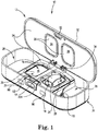
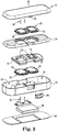
- an example recharging system 10 that includes a contact pad charger 12 and a rechargeable device 14.
- the rechargeable device 14 may interface with the contact pad charger 12 in a variety of orientations for charging and may also be enclosed for protection while charging.
- the contact pad charger 12 has an open position, in which the contact pad charger 12 can receive the rechargeable device 14 for charging.
- a charging cavity 16 may be defined by the contact pad charger 12 for receiving a body 18 of the rechargeable device 14 (e.g., device body) having a charging portion 20 (see FIG. 8 ), which may include charging portion 20Aand charging portion 20B(see FIG. 6 ), and an optional non-charging portion 19 (see FIG. 6 ).
- an extension portion 22 of the rechargeable device 14 is receivable into a well 26 of the contact pad charger 12.
- the contact pad charger 12 may include a liner 24 and conductors 28, 29 that define the charging cavity 16.
- the conductors 28, 29 may be compressible.
- Each conductor 28, 29 each may define a contact pad 25 that is flexible.
- the contact pad 25 may be described as providing a spring-like or resiliently deformable response.
- the charging cavity 16 may be sized and shaped to receive the device body 18 in more than one orientation for charging.
- the device body 18 may be rested on either side 21, 23 (see FIG. 6 ) and in various rotational orientations while resting in the charging cavity 16.
- the rechargeable device 14 When resting on a side 21, 23, the rechargeable device 14 may appear to lie flat, in a natural position within the charging cavity 16.
- the contact pad charger 12 may include a base 30 and a lid 32, which may be opened for exposing the charging cavity 16 and may be closed to initiate charging of the rechargeable device 14.
- the contact pad charger 12 may also include a pin assembly 34 for disconnecting the electrical connection between the conductors 28 of the base 30 and the conductors 29 of the lid 32, for example, when the lid 32 is opened. In some embodiments, the rechargeable device 14 cannot be charged until the lid 32 is closed.
- the rechargeable device 14 may be a hearing device, such as a BTE, as shown in the illustration.
- the device body 18 includes one or more sides 21, 23 (see FIG. 6 ) having the charging portion 20.
- the charging portion 20 provides an electrical path from the exterior (e.g., outer surface) of the rechargeable device 14 to a power storage device 132 (see FIG. 7 ) within the device body 18, which may be used to power the device 14 and may require recharging from time-to-time.
- the device body 18 may include more than one charging portion 20.
- the device body 18 includes a first side 21 with a first charging portion 20A(see also FIG. 8 ) and a second side 23 opposite the first side 21 with a second charging portion 20B(see FIG. 8 ).
- the second charging portion 20B may be symmetrical, or mirror, the first charging portion 20A.
- Each charging portion 20 may include a conductive material, such as gold, copper, or any other suitable conductive metal or material. In one or more embodiments, the conductive material is rigid.
- Other portions of the device body 18 may be non-conductive, and one or more portions may be formed of a material that is suitable for contact with the skin of a user, inside or outside of the ear.
- the extension portion 22 may extend from the device body 18.
- the extension portion 22 may be non-charging (e.g., may not include an exterior contact for charging).
- the extension 22 may include components that can be powered.
- the extension portion 22 may include a transducer to produce sound, which may be inserted into an ear or ear canal during use and is electrically powered by the device body 18.
- the rechargeable device 14 does not include an extension portion 22 (e.g., ITC, ITE, or CIC type hearing aids), and the device body 18 defines most or all of the exterior shape of the rechargeable device 14.
- the extension portion 22 may be permanently or removably attached to the device body 18.
- the contact pad charger 12 accommodates the device body 18 with the extension portion 22 attached.
- the extension portion 22 may extend out of the charging cavity 16 and over the liner 24 of the contact pad charger 12, terminating in the well 26 of the contact pad charger 12.
- the well 26 may surround and protect the extension portion 22 while the rechargeable device 14 is placed in the contact pad charger 12.
- the well 26 may be modular and be formed from a housing that is separate from housings 31, 33 and can be coupled or mated to the contact pad charger 12 in a permanent or releasable manner.
- the contact pad charger 12 does not include the well 26, and the extension portion 22 may extend out of the contact pad charger 12.
- the well 26 may be positioned laterally relative to the charging cavity 16 in the contact pad charger 12.
- the contact pad charger 12 may include two wells 26.
- the lateral arrangement of wells 26 with one or more charging cavities 16 can contribute to a low-profile (e.g., height) overall for contact pad charger 12, which may be convenient for storage or travel.
- the contact pad charger 12 may form an elongate rectangular or tube-like shape.
- the charging cavity 16 may define a space larger than the rechargeable device 14 to be able to receive the rechargeable device 14 in more than one orientation when one of the sides 21, 23 (see FIG. 6 ) of the rechargeable device 14 rests in the charging cavity 16 (e.g. the charging surface 36 formed on the conductor 28, which may be described as a floor of the charging cavity 16).
- the rechargeable device 14 may be freely rotated in the charging cavity 16 while one of the sides 21, 23 of the rechargeable device 14 rests in the charging cavity 16.
- the rechargeable device 14 may be freely rotated up to 180 degrees, up to 90 degrees, up to 45 degrees, up to 30 degrees, up to 15 degrees, or up to 10 degrees within the charging cavity 16 during charging.
- the rechargeable device 14 may be placed on either side 21, 23 (see FIG. 6 ) regardless of the particular polarities of the charger 12 or the device 14. Either or both of the charger 12 and the device 14 may have a predetermined charging polarity.
- the conductor 29 of the lid 32 may be electrically positive relative to the conductor 28 of the base 30 when connected to a power source 48.
- one side 21, 23 (see FIG. 6 ) of the rechargeable device 14, and related charging portions 20 may be electrically positive relative to the other side 21, 23 of the rechargeable device 14, and related charging portions 20.
- one or both of the charger 12 and the device 14 may include power management electronics for accommodating either orientation of the device 14 in a charging cavity 16 (e.g., a "right side up” or an “upside-down” polarity).
- the device 14 may include a rectifying circuit, as is further described herein.
- the charging cavity 16 is larger than the rechargeable device 14 in at least one dimension when the rechargeable device 14 is resting in the charging cavity 16. In some embodiments, the charging cavity 16 is larger than the rechargeable device 14 in two dimensions when the rechargeable device 14 is resting in the charging cavity 16. For example, such dimensions may be substantially parallel to a charging surface 36 of the charging cavity 16.
- the charging cavity 16 is formed as a rectangular prism with rounded corners and side surfaces formed by the liner 24 and top and bottom surfaces formed by the conductors 28, 29, which may be compressible conductors, and may be described as contact pads 25 with flexible charging surfaces 36.
- the charging cavity 16 may be any suitable shape for accommodating the rechargeable device 14 and making contact with its charging portions 20.
- one or more of the conductors 28, 29 are compressible. In some embodiments, one of the conductors 28, 29 is compressible and one of the conductors 28, 29 is non-moveable or non-compressible.
- Each of the conductors 28, 29 may conduct electrical power throughout its cross-section.
- the conductors 28, 29 may be compressible and may be formed of a resiliently deformable material.
- the compressible conductors 28, 29 are formed of an electrically conductive elastomer material (e.g., is elastomeric).
- the compressible conductors 28, 29 are formed of a material capable of withstanding periodic use of cleaning solvents to remove residue from the surface of the conductor.
- the compressible conductors 28, 29 are formed of a material free of mechanical or electrical hysteresis, which may prevent deformation over time that may adversely affect charging.
- the compressible conductors 28, 29 include a carbon-doped silicone rubber.
- the device body 18 of the rechargeable device 14 is rigid and non-flat, and the conductors 28, 29 are compressible and can at least partially conform to the rigid and non-flat shape of the device body 18 (e.g., including charging portions 20 and non-charging portions 19 of the body 18 as shown in FIG. 6 ) to maintain electrical contact with the surface of the charging portions 20.
- the charging cavity 16 is defined by two compressible conductors 28, 29, which oppose one another. In some embodiments, one of the conductors 28, 29 is compressible and the other conductor 28, 29 is rigid.
- Compressible conductors 28, 29 may have an inherent electrical resistance value that varies in response to the amount of deformation of the material, such as compression, flexion, or stretch in the material. Further, compressible conductors 28, 29 may appear to have a variable resistance due to build-up of ambient contaminants (e.g., oil residue and dust) on exposed surfaces (e.g., flexible charging surfaces 36) of the conductors 28, 29 or the charging portion 20 in contact with the conductors 28, 29. In some embodiments, the resistance of compressible conductors 28, 29 may appear to vary up to about one order of magnitude while still maintaining a high enough conductivity, or low enough resistance, to provide a desirable charging rate for the rechargeable device 14 (e.g., on the order of seconds, minutes, or hours).
- ambient contaminants e.g., oil residue and dust
- the resistance across compressible conductors 28, 29 may be defined to include both inherent and external variations.
- the resistance across each compressible conductor 28, 29 may range from about 100 ohms, about 200 ohms, or about 300 ohms (e.g., when clean) to about 1500 ohms, about 1300 ohms, or about 1200 ohms (e.g., when dirty).
- the resistance across the compressible conductors 28, 29 may range from about 300 ohms to about 1200 ohms while being capable of maintaining a desirable charging rate of the rechargeable device 14.
- Heat may be dissipated across the compressible conductors 28, 29 due to the inherent resistance.
- the resistance may encourage drying of the rechargeable device 14, which may be particularly useful in humid environments.
- the resistance may cause the compressible conductors 28, 29 to increase in temperature by greater than or equal to about 2 degrees Centrigrade, about 4 degrees Centrigrade, or about 6 degrees Centrigrade.
- the resistance may cause the compressible conductors 28, 29 to increase in temperature by no more than about 10 degrees Centigrade, about 8 degrees Centigrade, about 6 degrees centigrade, about 4 degrees Centigrade, or about 2 degrees Centigrade.
- the temperature may increase in a range from about 2 degrees Centigrade to about 6 degrees Centigrade. In one or more embodiments, the temperature may increase by about 4 degrees Centigrade.
- the liner 24 of the contact pad charger 12 may be formed of a non-conductive material (e.g., electrically insulating material).
- the liner 24 may be formed of a resiliently deformable material.
- the liner 24 is formed of a semirigid material, which may be a low durometer material.
- the liner 24 has a lower durometer than the compressible conductors 28, 29 to allow extrusion outward when compressed.
- the liner 24 may be formed of any suitable material capable of at least partially defining the charging cavity 16.
- the lid 32 is attached to the base 30 and is moveable between the open position (see FIG. 1 ) and a closed position (see FIGS. 3-4 ). In some embodiments, the lid 32 covers charging cavities 16 and wells 26. In some embodiments, the lid 32 may cover only one or more charging cavities 16.
- the base 30 and the lid 32 may each include a housing 31, 33 that defines at least a portion of an exterior (e.g., outer surface) of the contact pad charger 12.
- the housings 31, 33 may be formed of a plastic or any other suitable material for forming a container. In some embodiments, the housings 31, 33 are rigid.
- the lid 32 may be hingedly attached to the base 30.
- any other suitable attachment may be used, such as a sliding attachment or a releasable attachment.
- the base 30 includes the compressible first conductor 28, and the lid 32 includes the compressible second conductor 29.
- the base 30 includes two compressible first conductors 28, and the lid 32 includes two compressible second conductors 29.
- Each pair of conductors 28, 29 forms the charging cavity 16 and allows a pair of rechargeable devices, such as rechargeable device 14, to be charged concurrently.
- pairs of first conductors 28 may be positioned laterally relative to one another, and pairs of second conductors 29 may be positioned laterally relative to one another.
- a portion of the liner 24 separates the two charging cavities 16. In some embodiments (not shown), the liner 24 does not separate the two charging cavities 16.
- the lid 32 may be moved into an open position to expose the charging cavity 16 and to allow placement of the device body 18 into the charging cavity 16 and the extension portion 22 into the adjacent well 26.
- the rechargeable device 14 may be placed in either natural resting position on either side 21, 23 (see FIG. 6 ) of the device body 18 on the conductor 28 of the base 30 and in various rotational orientations.
- the charging portions 20 may be, but do not need to be, in electrical contact with the conductors 28, 29 of the base 30 or the lid 32 when the contact pad charger 12 is in in the open position.
- the lid 32 may be moved into a closed position with the rechargeable device 14 in the particular orientation as placed, and the lid 32 may be secured to the base 30 by a securing mechanism 92, such as a releasable tab and detent assembly.
- a securing mechanism 92 such as a releasable tab and detent assembly.
- the first and second conductors 28, 29 are positioned to contact first and second charging portions 20A,B(see FIG. 8 ), respectively or vice versa.
- the rechargeable device 14 may be compressed between first and second conductors 28, 29 of the charging cavity 16. The compression may facilitate contact between the conductors 28, 29 and the charging portions 20. Also, the compression may facilitate securing the rechargeable device 14 within the charging cavity 16 of the contact pad charger 12, for example, while the contact pad charger 12 is moved or transported while being charged.
- the pin assembly 34 of the contact pad charger 12 may be at least partially disposed on the base 30 and the lid 32.
- the pin assembly 34 may include two opposing pins (e.g., pogo pins), with one attached to each of the base 30 and the lid 32, and at least one pin being spring-loaded to engage the other when the lid 32 is closed.
- the pin assembly 34 may separate the pins to electrically uncouple or disconnect the one or more conductors 29 of the lid 32 from the power source 48 when the lid 32 is opened.
- the separable portions of the pin assembly 34 may engage to electrically couple or connect the conductors 29 of the lid 32 to the power source 48 when the lid 32 is closed. As the opposing pins engage and disengage, the pins may scratch one another.
- the lid 32 may be described as a scratching connect-disconnect lid.
- the contact pad charger 12 does not include a power switch (e.g., on/off switch). In some embodiments, closing the lid 32 turns on the contact pad charger 12 or otherwise completes a circuit to activate charging and opening the lid turns off the contact pad charger or otherwise breaks the circuit.
- a power switch e.g., on/off switch
- the pin assembly 34 is adjacent to the hinged attachment between the base 30 and the lid 32. In some embodiments, any other suitable position may be used. With a separable pin assembly 34, a conductive object in accidental contact with the first and second conductors 28, 29, while the lid 32 is in the open position, may be less likely to cause an electrical short and damage electronics in the contact pad charger 12. Although a pin assembly 34 is shown, any suitable type of assembly or device for establishing a selective electrical connection may be utilized.
- the pin assembly 34 may facilitate the use of a modular lid 32.
- the lid 32 may be removable and replaceable with a different lid 32 that may be designed to specifically fit other devices.
- the base 30 and the lid 32 are not connected by an electrically conductive wire or flex circuit.
- the pin assembly 34 provides the electrical connections between the base 30 and the lid 32.
- the lid 32 may be removably attached or hinged to the base 30, and the pin assembly 34 may include a base portion and a lid portion being separable from each other.
- active components of the contact pad charger 12 may be disposed on or within the base 30 (e.g., indicators, batteries, controllers), except for passive elements on or within the lid 32 (e.g., conductors).
- the color of the conductors 28, 29 may be different from the liner 24 to provide contrast between the charging cavity 16 and other portions of the contact pad charger 16.
- the liner 24 may form a functional depth to the charging cavity 16 that also provides an easily discernable depression for resting the rechargeable device 14.
- An indicator 90 may provide a user with an indication related to the status of the contact pad charger 12, which may, for example, be visual or aural.
- the indicator 90 is a visual indicator that is positioned to be visible to the user when the contact pad charger 12 is closed (e.g., on the contact pad charger 12).
- Non-limiting examples of indicators include an LED, an LCD, an OLED, and a speaker.
- the indicator 90 may be remote from the contact pad charger 12 (e.g., on a smartphone connected by wire or wirelessly to the contact pad charger 12).
- Non-limiting examples of indications include statuses related to a charging progress, a charging error, or a cleaning reminder.
- the indicator 90 may be activated by any suitable condition, such as the closing of the lid 32, placement of the rechargeable device 14 into the charging cavity 16, or some other condition related to the contact pad charger 12 (e.g., low battery voltage or connection to external power supply).
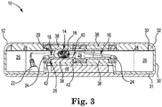
- the contact pad charger 12 is shown in the closed position with the rechargeable device 14 placed for charging in the charging cavity 16.
- the rechargeable device 14 may engage flexible charging surfaces 36 of compressible conductors 28, 29 in the closed position of the contact pad charger 12.
- optional insulators 38 may be provided between the conductors 28, 29 and the respective housings 31, 33 of the base 30 and the lid 32 to provide additional cushion travel.
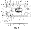
- the conductors 28, 29 may define an interior portion 40 and a perimeter portion 42.
- the flexible charging surface 36 of each conductor 28, 29 may be defined by the interior portion 40.
- the perimeter portion 42 may be electrically coupled to the contact plate 44, which can electrically couple the rechargeable device 14 to charging electronics in the contact pad charger 12, such as an optional power source 48 via the interior portion 40.
- the perimeter portion 42 may be coupled between the contact plate 44 and a retainer frame 46.
- Various components of the contact pad charger 12 may be coupled by any suitable means, such as an adhesive (e.g., double-sided tape or glue).
- the insulators 38 are formed of a different material than the conductors 28, 29.
- the insulators 38 may be formed of electrically insulating, or non-conductive, material.
- the material of the insulators 38 may be resiliently deformable.
- the insulators 38 may be described as compressible, similar to the conductors 28, 29.
- the insulators 38 have a lower durometer than the compressible conductors 28, 29 to allow the conductors to extrude when compressed.
- the insulators 38 have a significantly lower durometer than the compressible conductors 28, 29, such as about 10% lower, about 20% lower, about 25% lower, about 33% lower, about 50% lower, or even lower.
- the insulators 38 are formed of a closed cell foam material.
- the conductors 28, 29 may be pre-formed and placed over the insulator 38.
- the conductors 28, 29 may be formed of a transfer molded piece of material.
- the conductors 28, 29 may be printed or deposited onto the insulator 38, for example, as a conductive ink or paint.
- the conductors 28, 29 may be thick enough to provide sufficient electrical conductivity yet thin enough to provide sufficient deformability to nest the rechargeable device 14 in the charging cavity 16.
- the conductors 28, 29 have a thickness that is less than about 200 mils (e.g., 0.2 inches), less than about 100 mils, less than about 75 mils, less than about 50 mils, or less than about 25 mils. In some embodiments, the conductors 28, 29 have at thickness of about 50 mils.
- the insulators 38 may be thicker than the conductors 28, 29.
- the insulators 38 may be thicker by about 1.5, about 2, or about 3 times the thickness of the conductors 28, 29. In some embodiments, the insulators 38 are about 2 times the thickness of the conductors 28, 29.
- One of the conductors 28, 29 and one of the insulators 38 may together define the contact pad 25 and may be described as a pillow block.
- the contact pad 25 may nest at least one side 21, 23 (see FIG. 6 ) of a resting rechargeable device 14, particularly upon closure of the lid 32.
- an example contact pad 25 extends from a flat surface, such as a housing 31, 33 of the base 30 or lid 32, and includes one of the compressible insulators 38 supporting one of the compressible conductors 28, 29 at least adjacent to the interior portion 40.
- a perimeter portion 42 of the compressible conductor 28, 29 can be directly coupled to a contact plate 44 to form an electrical connection.
- the perimeter portion 42 and the contact plate 44 may be laterally adjacent to the insulator 38.
- the contact plate 44 can be coupled to the same surface of the respective housing 31, 33 as the insulator 38.
- the perimeter portion 42 may be compressed between the contact plate 44 and the retainer frame 46, for example, by a fastener that extends between the respective housing 31, 33 and the retainer frame 46.
- a side wall may be formed between the interior portion 40 and the perimeter portion 42 based on the height of the insulator 38 minus the height of the contact plate 44.
- the insulators 38 are interior to perimeter portions 42 and contact plates 44. In some embodiments, either or both of the perimeter portions 42 and contact plates 44 may not completely surround the interior portion 40 while still providing a high conductivity (e.g., low resistance) path between the interior portion 40 and the power source 48. As shown, the perimeter portions 42 and contact plates 44 surround the insulator 38 on at least two sides. In some embodiments, the perimeter portions 42 and contact plates 44surround the insulator 38 on four sides. In some embodiments, the perimeter portions 42 and contact plates 44 extend entirely around the insulator 38.
- the contact pads 25 e.g., pillow blocks
- the contact pads 25 form relatively flat flexible charging surfaces 36 (see, e.g., the right charging cavity 16 as shown in FIG. 3 ).
- the low walls of the liner 24 may provide easy access for cleaning the flexible charging surfaces 36.
- the flexible charging surface 36 or interior portion 40 of each conductor 28, 29 may define a contact area larger than corresponding charging portions 20 on the device body 18.
- the flexible charging surface 36 or interior portion 40 may define a contact area larger than a corresponding profile of an entire side 21, 23 of the device body 18 (e.g., profile of the device body 18 when resting on the flexible charging surface 36).
- the liner 24 may at least in part define a boundary of the flexible charging surface 36, which may be a rectangular area having edges ranging from about 1.2 inches to about 1.5 inches in length.
- a rechargeable device 14 is shown in one of the charging cavities 16 (see, e.g., left charging cavity 16 as shown in FIG. 3 ) with the lid 32 closed.
- the width of the rechargeable device 14 is about equal to, but may be greater than, the height of the charging cavity 16 between the conductors 28, 29 of the base 30 and the lid 32.
- the width of the rechargeable device 14 may also be described as the height of the rechargeable device 14 when resting in the charging cavity 16.
- a pair of contact pads 25 may accommodate this height difference and may accommodate a range of height differences depending on the particular rechargeable device placed into the charging cavity 16, particularly when at least one contact pad 25 is compressible.
- the conductor 28, 29 may extrude into the insulator 38 and outwardly into the low-durometer liner 24.
- the insulator 38 may also be compressed between the conductor 28, 29 and the housing 31, 33 of the base 30 or lid 32.
- the extension portion 22 of the rechargeable device 14 is shown in one of the wells 26 (e.g., left well as shown in FIG. 3 ).
- a gap or space may be formed between the liners 24 of the base 30 and the lid 32 between the charging cavity 16 and the adjacent well 26 through which the extension portion 22 may extend from the body 20 of the rechargeable device 14.
- Compressible conductors 28, 29 may define a variable resistance between the interior portions 40 and the perimeter portions 42 in response to the deformation of each conductor 28, 29, for example, by the size and shape of the rechargeable device 14, as well as the particular orientation, which may vary with each placement. In some orientations, the rechargeable device 14 may not deform the conductors 28 of the base 30 and the lid 32 evenly (e.g., to the same degree or in the same manner).
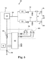
- the contact pad charger 12 can include charging electronics 100 for delivering electrical power to the rechargeable device 14 from a power supply 104.
- the contact pad charger 12 may also include a controller 102 that may facilitate charging and may also communicate with the rechargeable device 14 for updating one or more indicators 90 on the contact pad charger 12.
- the controller 102 may be coupled to the power supply 104.
- the power supply 104 can include a power source 48, such as a battery, a connection to an external power supply, or both.
- the power source 48 is a battery capable of charging a rechargeable device over several days of use without itself being recharged (e.g., a 900 mAh Li-ion rechargeable battery may be used for portable charging of a hearing assistance device for about 5-7 days).
- the power supply 104 may also include a boost regulator 110 to provide a supply voltage across a first power terminal 106 and a second power terminal 108. The supply voltage may be greater than the voltage from the power source 48 (e.g., source voltage).
- the power supply 104 can further include an overcurrent protection 120 (e.g., a resettable fuse, such as a positive temperature coefficient device) between the power source 48 and electrically-connected components.
- an overcurrent protection 120 e.g., a resettable fuse, such as a positive temperature coefficient device
- the first power terminal 106 may be considered a positive terminal.
- the second power terminal 108 may be considered a ground or a negative terminal.
- the positive or negative orientation of the terminals 106, 108 may be defined as a polarity and may be based on the orientation of the power source 48, which may be a direct current (DC) power source.
- Current from the power supply 104 at the first power terminal 106 may be split between a first sense circuit 112 and a second sense circuit 114, which may each be used to detect modulation in a first current portion 116 and a second current portion 118, for communication between the rechargeable device 14 and the controller 102.
- the sense circuits 112, 114 may be configured to detect communication current over the powerline having a substantially high impedance (e.g., due the conductors 28, 29).
- the first current portion 116 can provide charging to conductors 28L, 29L(e.g., the left conductor 28 coupled to the base 30 and the left conductor 29 coupled to the lid 32 to form the left charging cavity 16).
- the second current portion 118 can provide charging to conductors 28R, 29R(e.g., the right conductor 28 coupled to the base 30 and the right conductor 29 coupled to the lid 32 to form the right charging cavity 16 as shown in FIG. 2 ).
- a pin of the pin assembly 34 is electrically connected to each of the conductors 29L, Rof the lid 32.
- the pin assembly 34 forms an open circuit to disrupt the flows of the first and second current portions 116, 118 when the lid 32 is opened.
- the pin assembly 34 forms a closed circuit to operably connect the conductors 29L, Rto the power supply 104 when the lid 32 is closed to receive electrical power for charging the rechargeable device 14.
- the power source 48 may include a battery, which may be rechargeable or disposable. Additionally or alternatively, the power source 48 may include a connection to an external power supply, which may be a USB connection, an AC-DC adapter, or any other suitable source of electrical power.
- an external power supply which may be a USB connection, an AC-DC adapter, or any other suitable source of electrical power.
- the power source 48 provides electrical power at about 5 VDC or less.
- the boost regulator 110 may transform the electrical power from the power source 48 to provide a higher voltage (e.g., higher than 5 VDC).
- the boost regulator 110 provides electrical power at the first power terminal 106 at about 12 VDC.
- the power source 48 provides electrical power greater than about 5 VDC (e.g., 12 VDC), and a boost regulator 110 may not be necessarily be used.
- the higher voltage output voltage allows the charging electronics 100 to compensate for the variable resistance across the conductors 28, 29.
- the corresponding current at the first power terminal 106 may depend on the current demand from the connected rechargeable device at conductors 28L, 29L, conductors 28R, 29L, or combinations thereof.
- the controller 102 may be coupled to the contact pad charger 12 (see FIGS. 1-5 ), for example, at the base 30 or the lid 32. In some embodiments, the controller 102 is coupled to the base 30. In some embodiments, the controller 102 is disposed inside the base 30.
- the controller 102 is configured to detect modulations in either or both of the first and second current portions 116, 118 via the respective sense circuit 112, 114 as a communication signal.
- a sense circuit 112, 114 may utilize a low-impedance, in-series detection circuit to measure modulations in a current portion 116, 118.
- the sense circuits 112, 114 are operably connected to the controller 102 via nodes A and B (e.g., through a high-pass filter).
- the controller 102 receives a high-frequency communication signal corresponding to the modulations in the first and second current portions 116, 118.
- the communication signal may contain information from the rechargeable device 14 related to charging, which may be used to provide a charging signal to an indicator 90 on the contact pad charger 12.
- the controller 102 provides charging signals to one or more indicators 90 in response to the communication signal, such as an indicator 90Lassociated with a left charging cavity 16 and an indicator 90Rassociated with a right charging cavity 16. (see FIG. 3 )
- the indicators 90L, R may provide an indication associated with the respective charging cavity 16.
- the indicators 90L, R may provide separate indications particular to the respective charging cavity 16.
- the indicators 90 each include two or more LEDs powered and controlled by controller 102.
- the LEDs may be used to each indicate a different status, such as a charging progress, a charging error, or a cleaning reminder.
- the LEDs may also used together (e.g., four LEDs together may indicate 0%, 25%, 50%, 75%, and 100% charging progress).
- the indicators 90 may only provide a signal when the rechargeable device 14 is connected. In some embodiments, the indicators 90 may provide a signal even when no rechargeable device is connected to the charging electronics 100.
- the conductors 28, 29 forming the one or more charging cavities 16 may have the same or different resistance values.
- the recharging system 10 may be able to compensate for different resistance values with a power manager 130.
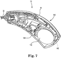
- the power manager 130 is disposed in the rechargeable device 14 along with other suitable charging electronics, such as charging electronics 200, as shown in FIGS. 6 to 8 , to regulate power delivery to a power storage device 132.
- the charging electronics 200 including the power manager 130 and the power storage device 132 may be disposed in the rechargeable device 14 and maintained within a housing 140 defining an exterior of the device body 18.
- the housing 140 may include the charging portions 20 and the non-charging portions 19.
- the power storage device 132 may be disposed near an end of the device body 18 opposite the extension portion 22 that extends from the device body 18.
- the power storage device 132 is rechargeable.
- the power storage device 132 may be a battery, which may be based on Li, Ag-Zn, Ni-MH, or any other suitable rechargeable chemistry for a battery cell.
- the power storage device 132 may be removable or permanently disposed within the device body 18.
- the device body 18 may include an optional pin 142 for hinging a battery door (not shown), which may extend from one side 21, 23 of the device body 18 to the other side 21, 23. Any suitable technique for providing a removable power storage device 132 may be utilized.
- the power storage device 132 is not removable, and a pin 142 is not included.
- the charging portions 20 may be positioned in a location near where the pin 142 would be located, which may facilitate utilization of the same antenna designs for both removable and non-removable device types.
- the charging portions 20 may be positioned in any other suitable location along the device body 18 that generally faces the conductors 28, 29 (see FIGS. 1-5 ) when positioned for charging. In the illustrated embodiment, the charging portions 20 are flush with the surface defined by the non-charging portions 19. In some embodiments, the charging portions 20 may recess from or protrude from the surface defined by the non-charging portions 19.
- the contact pads 25 of the contact pad charger can conform and contact such recessed or protruding charging portions 20.
- the housing 140 of the device body 18 can take any suitable shape.
- the housing 140 of the device body 18 is generally convex in shape.
- the charging portions of the device body 18 may also be similarly convex or flat in shape to maintain a continuous contour around the device body 18.
- the convex contours of the housing 140 may be nested in compressible contact pads 25 (e.g., pillow blocks) of the charging cavity 16 (see FIGS. 1-5 ).
- the power manager 130 may be electrically coupled to the terminals 106, 108 (see FIG. 5 ) of the contact pad charger 12 when placed in the charging cavity 16 and the lid 32 is closed (see FIGS. 3-4 ).
- the power manager 130 may include a rectifying circuit 150, which allows the rechargeable device 14 to receive electrical power at any polarity across the charging portions 20, to provide electrical power at a predetermined DC polarity to charging electronics 200 within the rechargeable device 14 (e.g., the power storage device 132).
- the rechargeable device 14 can be charged with either side 21, 23 placed down in the charging cavity 16 and is not limited to a particular "right side up" orientation.
- the power manager 130 may be included in the contact pad charger 12 instead of the rechargeable device 14.
- the charging of the power storage device 132 in the rechargeable device 14 may be more difficult to manage current flow received at the power storage device 132 due to variations in resistance across the conductors 28, 29 (see FIGS. 1-5 ), which may vary due to inherent and external contributing factors.
- the charging electronics 200 include the first contact terminal 20Aand the second contact terminal 20Bcorresponding to charging portions 20 on each opposing side 21, 23 of the rechargeable device 14, which can receive an input voltage, for example, from the contact pad charger 12 (see FIGS. 1-5 ).
- the contact terminals 20A Bare electrically coupled to the power manager 130, which includes a rectifying circuit 150, which can translate the incoming input voltage to an appropriate predetermined polarity, a voltage regulator 152, and a power controller 154.
- the charging electronics 200 may be operatively coupled to device electronics 156, such as electronics to receive signals and produce sound in a hearing assistance device.
- the power manager 130 may be described as being electrically coupled between the terminals 106, 108 of the power supply 48 (see FIG. 5 ) in the contact pad charger 12, as well as being electrically coupled between the conductors 28, 29 (see FIGS. 1-5 ) in the contact pad charger 12. Due to the individual voltage drop across at least each conductor in the contact pad charger 12 (e.g., a first and a second voltage drop), the input voltage across contact terminals 20A, Band received by the power manager 130 may be less than the supply voltage from the power supply of the contact pad charger 12. In some embodiments, the input voltage remains high enough for charging the power storage device 132, which may have a minimum voltage threshold for charging.
- the input voltage across contact terminals 20A, B may also vary in magnitude depending on the variable resistances across the conductors 28, 29 in the contact pad charger 12 (see FIGS. 1-5 ), which may depend, for example, on the placement or type of the rechargeable device 14 in the contact pad charger 12. Movement of the rechargeable device 14 relative to the contact pad charger 12 may also cause variations in conductor resistance.
- the voltage regulator 152 may allow the power manager 130 to provide a regulated output voltage to the power controller 154, the power storage device 132, the device electronics 156, or a combination thereof. Due to the voltage drops across components in the power manager 130, the regulated output voltage may be less than the input voltage. In one or more embodiments, a regulated output voltage is provided to the power controller 154, which manages the distribution of power to the power storage device 132 and to the device electronics 156.
- the power manager 130 can modulate the current corresponding to the input voltage across contact terminals 20A, B.
- the power controller 154 may be configured to modulate the current drawn while charging the power storage device 132 or powering the device electronics 156.
- the power manager 130 may modulate the current to communicate with the controller 102 in the contact pad charger 12 (see FIG. 5 ).
- the power manager 130 communicates a data to the controller 102 and/or vice versa.
- the power manager 130 communicates the input voltage received across contact terminals 20A, Bto the controller 102.
- an estimated resistance across the conductors 28, 29 in the contact pad charger 12 can be determined, for example, in response to an estimated voltage difference between a known supply voltage and the detected input voltage.
- the controller 102 is configured to calculate the estimated resistance.
- the power manager 130 is configured to calculate the estimated resistance.
- the estimated resistance is determined in response to the resistance across at least two conductors 28, 29, such as conductors 28L, 29Lor conductors 28R, 29R. If the estimated resistance is above a target resistance (e.g., about 1200 to 1500 ohms), the rechargeable device may not receive sufficient current to charge the power storage device 132 in a desired amount of time for charging (e.g., a few hours). However, the supply voltage may be set sufficiently high (e.g. 12 VDC) to allow the power storage device 132 to continue charging, even under such high resistance conditions.
- a target resistance e.g., about 1200 to 1500 ohms
- the supply voltage may be set sufficiently high (e.g. 12 VDC) to allow the power storage device 132 to continue charging, even under such high resistance conditions.
- the controller 102 may be configured to provide a cleaning reminder when an estimated resistance across one or more conductors 28R,L, 29R,L(see FIGS. 1-5 ) is higher than a high resistance threshold (or an input voltage/current is below a low voltage/current threshold).
- the cleaning reminder may indicate that the charging cavity 16 is dirty, which may prompt a user (e.g., via the indicator 90 on the contact pad charger 12 as shown in FIGS. 1-5 ) to clean the cavity 16.
- the user may be prompted to clean the conductors 28, 29 of the contact pad charger 12 or the charging portions 20 of the rechargeable device 14.
- the cleaning can facilitate the restoration of desirable charging times.
- the recharging system described provides freedom-of-placement of a rechargeable device (e.g., a hearing assistance device) within large charging cavities or receiving pockets in a contact pad charger, which may allow a user to interact with the recharging system like a wireless charger without the need for strict placement of the device within the charger.
- the recharging system described provides a direct connection between the rechargeable device and the power supply in the charger, which may allow for less complicated electronics and a more efficient use of power when charging.
- FIGS. 9 to 11 Various aspects of an example recharging system useful for understanding the invention may be used with a pogo-style embodiment of a contact pad charger, such as contact pad charger 212 in recharging system 200 shown in FIGS. 9 to 11 .
- the contact pad charger 212 may be similar to contact pad charger 12 except as described herein.
- the specific features of contact pad charger 212 are not limiting, and embodiments that include or exclude one or more other aspects of the example recharging system are also contemplated.
- the contact pad charger 212 may include the pin assembly 34 and the power source 48.
- the same base 30 and lid 32 may be used with contact pad charger 212.
- the contact pad charger 212 may also define the wells 26.
- the rechargeable device 14 having the same circuitry may be charged with contact pad charger 212.
- the contact pad charger 212 differs from the contact pad charger 12 in shape of the cavity 216 and the use of conductors 228, 229 (e.g., pins).
- contact pad charger 212 includes conductors 228, 229 (e.g., pins, such as pogo-style pins) as conductors, for example, instead of conductors 28, 29.
- the conductors 228, 229 may be formed of any suitable conductive material.
- the conductors 228, 229 are formed of a metal material.
- Metal conductors 228, 229 may be compressible with a spring feature, which may allow the conductors to compress to accommodate the presence of the rechargeable device 14 in the charging cavity 216 and may apply a force to the rechargeable device to maintain an electrical connection therebetween. For example, as perhaps best shown in FIG. 11 , the conductor 229 would extend further into the charging cavity 216 without the presence of the rechargeable device 14.
- the conductive contact area of the conductors 228, 229 may be less than the contact area of the conductors 28, 29, and may be less flexible in terms of placing the rechargeable device 14.
- the metal conductors 228, 229 with spring features may vary less in inherent resistance than the compressible conductors 28, 29.
- the metal conductors 228, 229 with spring features may be described as not varying inherently in resistance.
- the charging electronics may not need to be as sophisticated when used with conductors 228, 229 instead of conductors 28, 29.
- the charging cavity 216 is specifically formed to the shape of the rechargeable device to secure the rechargeable device 14 during charging, particularly when the recharging system 200 is being transported.
- the liners 224 may at least partially define the charging cavity 216.
- the liner 224 may not deform in response to the rechargeable device 14 being placed therein.
- the liners 224 may define two opposing sides of the charging cavity 216. In some embodiments, a portion of the liners 224 is attached to the lid 32 and another portion of the liners is attached to the base 30. The conductors 228, 229 may extend through the corresponding liners 224 of the base 30 and the lid 32 to contact the rechargeable device 14.
- the contact pad charger 212 may be considered modular.
- the liners 224 may be removed and replaced with other liners having different shapes to accommodate rechargeable devices other than the rechargeable device 14.
- Coupled or “connected” refer to elements being attached to each other either directly (in direct contact with each other) or indirectly (having one or more elements between and attaching the two elements).
- orientation such as “top”, “bottom”, “side”, and “end”, are used to describe relative positions of components and are not meant to limit the orientation of the embodiments contemplated.
- an embodiment described as having a “top” and “bottom” also encompasses embodiments thereof rotated in various directions unless the content clearly dictates otherwise.
- references to "one embodiment,” “an embodiment,” “certain embodiments,” or “some embodiments,” etc. means that a particular feature, configuration, composition, or characteristic described in connection with the embodiment is included in at least one embodiment of the disclosure. Thus, the appearances of such phrases in various places throughout are not necessarily referring to the same embodiment of the disclosure. Furthermore, the particular features, configurations, compositions, or characteristics may be combined in any suitable manner in one or more embodiments.
- casting and/or treating an alloy means casting, treating, or both casting and treating the alloy).
- phrases "at least one of,” “comprises at least one of,” and “one or more of' followed by a list refers to any one of the items in the list and any combination of two or more items in the list.
Landscapes
- Engineering & Computer Science (AREA)
- Power Engineering (AREA)
- Computer Networks & Wireless Communication (AREA)
- Health & Medical Sciences (AREA)
- General Health & Medical Sciences (AREA)
- Neurosurgery (AREA)
- Otolaryngology (AREA)
- Physics & Mathematics (AREA)
- Acoustics & Sound (AREA)
- Signal Processing (AREA)
- Charge And Discharge Circuits For Batteries Or The Like (AREA)
Claims (6)
- Système comprenant :une alimentation (104) configurée pour fournir une tension d'alimentation entre une première borne (106) et une seconde borne (108) ; etun premier conducteur compressible (28, 29) couplé électriquement à la première borne (106) et définissant une première résistance variable en réponse à une compression du premier conducteur ; et étant caractérisé par :un gestionnaire d'alimentation (130) couplé électriquement entre le premier conducteur (28, 29) et la seconde borne (108), le gestionnaire d'alimentation (130) étant configuré pour :recevoir une tension d'entrée variable en réponse à une première chute de tension variable sur le premier conducteur (28, 29) ; etfournir une tension de sortie régulée en réponse à la tension d'entrée variable reçue, la tension de sortie régulée étant inférieure à la tension d'alimentation ; etun dispositif de stockage d'énergie (132) couplé électriquement au gestionnaire d'alimentation (130) et configuré pour recevoir la tension de sortie régulée pour la charge.
- Système selon la revendication 1, dans lequel le premier conducteur (28, 29) comprend un matériau élastomère.
- Système selon la revendication 1 ou 2, comprenant en outre un second conducteur compressible (28, 29) couplé électriquement à la seconde borne (108) et définissant une seconde résistance variable en réponse à une compression du second conducteur ;
dans lequel le gestionnaire d'alimentation (130) est couplé électriquement entre le premier conducteur (28, 29) et le second conducteur (28, 29), le gestionnaire d'alimentation (130) étant configuré pour recevoir en outre la tension d'entrée variable en réponse à une seconde chute de tension variable sur le second conducteur (28, 29). - Système selon l'une quelconque des revendications précédentes, dans lequel le gestionnaire d'alimentation (130) est configuré pour :recevoir une première partie de courant (116) d'un courant d'alimentation provenant de l'alimentation (104) ; etmoduler la première partie de courant (116) en réponse à la tension d'entrée variable ;dans lequel le système comprend en outre éventuellement un dispositif de commande (102) configuré pour :détecter la première partie de courant modulée ; etfournir un signal de charge en réponse à la première partie de courant modulée, le signal de charge représentant au moins l'un d'une progression de charge, d'une erreur de charge et d'un rappel de nettoyage ; etle dispositif de commande (102) est éventuellement configuré pour fournir le rappel de nettoyage en réponse au fait que la tension d'entrée variable est inférieure à un seuil de tension basse.
- Système selon l'une quelconque des revendications précédentes, dans lequel l'alimentation (104) comprend au moins un régulateur survolteur (110) configuré pour recevoir une tension de source inférieure à la tension d'alimentation fournie et une batterie.
- Système selon l'une quelconque des revendications précédentes, dans lequel le gestionnaire d'alimentation (130) est configuré pour rectifier la tension d'entrée variable reçue selon une polarité prédéterminée.
Applications Claiming Priority (1)
| Application Number | Priority Date | Filing Date | Title |
|---|---|---|---|
| US15/337,141 US10424955B2 (en) | 2016-10-28 | 2016-10-28 | Charging system with compressible contacts |
Publications (3)
| Publication Number | Publication Date |
|---|---|
| EP3316444A2 EP3316444A2 (fr) | 2018-05-02 |
| EP3316444A3 EP3316444A3 (fr) | 2018-06-20 |
| EP3316444B1 true EP3316444B1 (fr) | 2020-01-01 |
Family
ID=60119816
Family Applications (1)
| Application Number | Title | Priority Date | Filing Date |
|---|---|---|---|
| EP17195019.9A Active EP3316444B1 (fr) | 2016-10-28 | 2017-10-05 | Système de facturation à contacts compressibles |
Country Status (4)
| Country | Link |
|---|---|
| US (2) | US10424955B2 (fr) |
| EP (1) | EP3316444B1 (fr) |
| CN (1) | CN108023374B (fr) |
| DK (1) | DK3316444T3 (fr) |
Families Citing this family (43)
| Publication number | Priority date | Publication date | Assignee | Title |
|---|---|---|---|---|
| US9482882B1 (en) | 2015-04-15 | 2016-11-01 | Snapchat, Inc. | Eyewear having selectively exposable feature |
| US10993515B1 (en) * | 2017-08-28 | 2021-05-04 | Snap Inc. | Carry case for rechargeable eyewear devices |
| JP2019057961A (ja) * | 2017-09-19 | 2019-04-11 | パナソニックIpマネジメント株式会社 | 非接触充電装置 |
| KR102446172B1 (ko) * | 2017-10-27 | 2022-09-23 | 삼성전자주식회사 | 입출력 인터페이스를 통해 통신을 수행하는 방법 및 이를 위한 장치 |
| USD908617S1 (en) * | 2018-05-11 | 2021-01-26 | New Audio LLC | Earpiece charging case |
| US11128966B2 (en) * | 2018-06-08 | 2021-09-21 | Serene Group, Inc. | Charging and drying station for hearing aid device |
| CN109256832A (zh) * | 2018-09-30 | 2019-01-22 | 深圳市沃特沃德股份有限公司 | 充电组件及电子设备 |
| USD931206S1 (en) | 2019-02-28 | 2021-09-21 | New Audio, LLC | Earpiece charging case with window |
| USD931207S1 (en) | 2019-03-01 | 2021-09-21 | New Audio, LLC | Earpiece charging case with window |
| US11122378B1 (en) | 2019-08-06 | 2021-09-14 | Daniel R. Schumaier | Hearing aid dryer and disinfection kit |
| US11102588B2 (en) | 2019-08-06 | 2021-08-24 | Daniel R. Schumaier | Hearing aid dryer and disinfection kit |
| US11266757B2 (en) | 2019-08-06 | 2022-03-08 | Daniel R. Schumaier | Hearing aid dryer and disinfection kit with UV-reflective drying tray |
| US11092379B2 (en) | 2019-08-07 | 2021-08-17 | Ear Technology Corporation | Dryer and sanitizer for rechargeable electronic devices |
| SE544117C2 (en) * | 2019-10-31 | 2021-12-28 | Zound Industries Int Ab | A charging container for storing and charging a pair of wireless earbuds |
| GB2605041B (en) * | 2019-11-04 | 2023-11-22 | Cirrus Logic Int Semiconductor Ltd | Methods, apparatus and systems for personal audio device diagnostics |
| US11582566B2 (en) | 2019-12-02 | 2023-02-14 | Gn Hearing A/S | Hearing instrument charger device and system, and a method of manufacturing a holder therefor |
| US11792585B2 (en) * | 2019-12-02 | 2023-10-17 | Gn Hearing A/S | Alignment between charging elements of a hearing device and a charger |
| US11202157B2 (en) * | 2019-12-02 | 2021-12-14 | Gn Hearing A/S | Alignment between charging elements of a hearing device and a charger |
| EP4091342B1 (fr) | 2020-01-14 | 2024-10-09 | Starkey Laboratories, Inc. | Capteur optique dans un instrument auditif |
| US11167052B2 (en) | 2020-04-07 | 2021-11-09 | Daniel R. Schumaier | Ultraviolet light sanitizer |
| EP4143947A4 (fr) * | 2020-04-29 | 2025-02-26 | Cochlear Limited | Boîtier de recharge par induction |
| USD953982S1 (en) * | 2020-05-15 | 2022-06-07 | Lg Electronics Inc. | Combined cradle with charging pad for wireless earphones |
| USD1000378S1 (en) * | 2020-11-20 | 2023-10-03 | Bose Corporation | Charging case |
| USD979491S1 (en) * | 2020-12-08 | 2023-02-28 | Shenzhen Aoni Electronic Co., Ltd | Charging case for earphones |
| TWI755195B (zh) * | 2020-12-10 | 2022-02-11 | 仁寶電腦工業股份有限公司 | 聽力輔助裝置的收納盒 |
| US11765525B2 (en) * | 2020-12-11 | 2023-09-19 | Gn Hearing A/S | Hearing instrument charger device and system, and a method of manufacturing a holder therefor |
| TWI768643B (zh) * | 2021-01-06 | 2022-06-21 | 緯創資通股份有限公司 | 電子裝置與其之充電腳座 |
| USD999730S1 (en) | 2021-01-27 | 2023-09-26 | New Audio LLC | Earphone charging case |
| USD965973S1 (en) * | 2021-02-08 | 2022-10-11 | Xiwan Sun | Case with earphones |
| USD959830S1 (en) * | 2021-02-08 | 2022-08-09 | Xiwan Sun | Case with earphones |
| US11800271B2 (en) * | 2021-04-12 | 2023-10-24 | Derrick P. Golden | Microphone bed |
| USD978793S1 (en) * | 2021-04-16 | 2023-02-21 | Vitra Ag | Adaptor for electrical plugs |
| USD984421S1 (en) * | 2021-08-10 | 2023-04-25 | Besing Technology (Shenzhen) Co., Ltd. | Wireless earphones with charging case |
| USD1000409S1 (en) * | 2021-08-30 | 2023-10-03 | Shenzhen Xirui Technology Co., Ltd. | Set of earphones and charging case |
| USD1022889S1 (en) * | 2021-12-21 | 2024-04-16 | Scud (Fujian) Electronics Co., Ltd. | Wireless headset charging box |
| USD1024012S1 (en) * | 2022-01-13 | 2024-04-23 | Yifeng Zhang | Combined wireless earphones and charging case |
| EP4224664A1 (fr) * | 2022-02-08 | 2023-08-09 | GN Hearing A/S | Dispositif de boîtier |
| WO2023194749A1 (fr) * | 2022-04-07 | 2023-10-12 | Scanstrut Limited | Système d'alimentation sans fil pour dispositifs électriques portables sur des navires et des véhicules terrestres |
| USD1040784S1 (en) * | 2023-02-24 | 2024-09-03 | Besing Technology (Shenzhen) Co., Ltd. | Wireless earphones with charging case |
| USD1075712S1 (en) * | 2023-04-26 | 2025-05-20 | Jiaxing Le Mai Le Mai Trading Co., Ltd | Bone conduction earphones and case |
| USD1076884S1 (en) * | 2023-11-07 | 2025-05-27 | Besing Technology (Shenzhen) Co., Ltd. | Wireless earphones with charging case |
| USD1071895S1 (en) * | 2024-01-17 | 2025-04-22 | Guangdong Xizhongxi Technology Co., Ltd. | Set of earphones and charging case |
| USD1113159S1 (en) * | 2024-10-30 | 2026-02-17 | Shenzhen Oren Medical Technology Co., Ltd. | Phototherapy patch storage box |
Family Cites Families (62)
| Publication number | Priority date | Publication date | Assignee | Title |
|---|---|---|---|---|
| DE1917678B2 (de) * | 1969-04-05 | 1971-04-29 | Abstimmaggregat fuer hochfrequenz empfaenger | |
| US3675108A (en) * | 1971-10-12 | 1972-07-04 | Thomas H Nicholl | Induction charging device |
| US3964296A (en) * | 1975-06-03 | 1976-06-22 | Terrance Matzuk | Integrated ultrasonic scanning apparatus |
| US4097792A (en) * | 1976-12-09 | 1978-06-27 | Lester Electrical Of Nebraska, Inc. | Battery charger control circuit |
| JPH0830915B2 (ja) * | 1988-02-19 | 1996-03-27 | キヤノン株式会社 | 帯電部材、それを用いた帯電装置および電子写真装置 |
| EP0458273B1 (fr) * | 1990-05-21 | 1997-08-13 | Canon Kabushiki Kaisha | Dispositif de chargement, appareil de formation d'images avec un tel dispositif et unité de traitement montée de manière amovible dans l'appareil de formation d'images |
| DE4036374A1 (de) | 1990-11-15 | 1992-05-21 | Bsg Schalttechnik | Ladeeinrichtung fuer wiederaufladbare batterien |
| FR2688645A1 (fr) | 1992-03-13 | 1993-09-17 | Audiologie Prothese Innovation | Dispositif permettant la recharge de l'accumulateur d'une prothese auditive intra-auriculaire, prothese auditive utilisable avec ce dispositif et procede pour la fabrication de ce dispositif. |
| SE9201476L (sv) | 1992-05-11 | 1993-11-12 | Volvo Penta Ab | Förfarande för uppladdning av ett batteri |
| JP3240020B2 (ja) * | 1993-09-16 | 2001-12-17 | 本田技研工業株式会社 | 電動車用電源装置 |
| US5623550A (en) | 1995-03-08 | 1997-04-22 | Etymotic Research, Inc. | Battery power supply circuit which supplies correct power polarity irrespective of battery orientation |
| JPH09196978A (ja) * | 1996-01-16 | 1997-07-31 | Sekisui Chem Co Ltd | 微粒子電気抵抗測定装置 |
| US5742149A (en) | 1997-06-03 | 1998-04-21 | Motorola, Inc. | Adaptable battery charger system |
| US6275681B1 (en) * | 1998-04-16 | 2001-08-14 | Motorola, Inc. | Wireless electrostatic charging and communicating system |
| US6879809B1 (en) * | 1998-04-16 | 2005-04-12 | Motorola, Inc. | Wireless electrostatic charging and communicating system |
| US6399920B1 (en) | 2001-04-26 | 2002-06-04 | James D. Guinn | Hearing aid drying apparatus |
| US6664760B2 (en) | 2001-11-23 | 2003-12-16 | God Co., Ltd. | Cellular phone charger with data backup function and cellular phone data backup device |
| US6625900B1 (en) | 2002-01-14 | 2003-09-30 | Stewart W. Tobias | Hearing aid drying device |
| SE524203C2 (sv) | 2002-02-18 | 2004-07-06 | Creator Teknisk Utveckling Ab | Anordning för en batteriladdare |
| US6928372B2 (en) | 2003-07-29 | 2005-08-09 | Motorola, Inc. | Method for estimating time to full-charge in a rechargeable battery |
| FR2862558B1 (fr) * | 2003-11-20 | 2006-04-28 | Pellenc Sa | Outil portatif electrique autonome de puissance |
| US7515725B2 (en) | 2004-03-05 | 2009-04-07 | Phonak Ag | Electronic battery-powered hearing instrument, and method for operating such a hearing instrument |
| US20050253554A1 (en) | 2004-05-14 | 2005-11-17 | Interdigital Technology Corporation | Apparatus for backing up data stored in a portable device |
| US20060276190A1 (en) | 2005-05-19 | 2006-12-07 | Interdigital Technology Corporation | Method and apparatus for implementing a handoff between radio access networks deployed under different radio access technologies |
| US7710079B2 (en) * | 2005-07-19 | 2010-05-04 | Linear Technology Corporation | Power manager and power managing method for battery-powered application |
| US7620195B2 (en) | 2005-11-09 | 2009-11-17 | Zounds, Inc. | Rechargeable hearing aid |
| CN2850095Y (zh) * | 2005-12-03 | 2006-12-20 | 惠州市德赛电池有限公司 | 一种便携式可充电电源 |
| TW200807006A (en) | 2006-09-25 | 2008-02-01 | Jye Chuang Electronic Co Ltd | Automatic polarity detecting device for battery |
| US8329323B2 (en) * | 2007-01-31 | 2012-12-11 | Hewlett-Packard Development Company, L.P. | Battery pack heat transfer |
| DE102007013420A1 (de) | 2007-03-20 | 2008-10-02 | Siemens Audiologische Technik Gmbh | Hörvorrichtung mit spezieller Ladeschaltung |
| US20080240480A1 (en) | 2007-03-26 | 2008-10-02 | Pinnell Leslie J | Secondary Batteries for Hearing Aids |
| ATE526793T1 (de) | 2007-07-30 | 2011-10-15 | Siemens Medical Instr Pte Ltd | Hörvorrichtung mit beweglichem ladekontakt |
| DE102007042324B4 (de) | 2007-09-06 | 2012-08-30 | Siemens Medical Instruments Pte. Ltd. | In-dem-Ohr-Hörgerät mit Kontaktmittel und zugehöriges Batterieladegerät |
| DE102007044205B3 (de) | 2007-09-17 | 2009-04-23 | Siemens Medical Instruments Pte. Ltd. | Hörgerät |
| US8098962B2 (en) | 2007-11-20 | 2012-01-17 | Kabushiki Kaisha Toshiba | Signal processing method, apparatus, and program |
| TW200940962A (en) | 2008-03-18 | 2009-10-01 | Richtek Technology Corp | Circuit and method for detecting absent battery condition |
| CN102210080B (zh) | 2008-09-08 | 2015-06-03 | 创科电动工具科技有限公司 | 电池充电器 |
| AU2009295283A1 (en) | 2008-09-29 | 2011-09-15 | Wilson Lee | Multi-chemistry battery charging system and method of identifying and improved charging technique for primary and secondary dry-cell batteries |
| US8777863B2 (en) * | 2009-06-10 | 2014-07-15 | Cardiac Pacemakers, Inc. | Implantable medical device with internal piezoelectric energy harvesting |
| DE102009030070A1 (de) | 2009-06-22 | 2010-12-23 | Sennheiser Electronic Gmbh & Co. Kg | Transport-und/oder Aufbewahrungsbehälter für aufladbare drahtlose Hörer |
| US8638011B2 (en) * | 2009-07-10 | 2014-01-28 | Protonex Technology Corporation | Portable power manager operating methods |
| DE102009033898B3 (de) | 2009-07-20 | 2010-11-25 | Siemens Medical Instruments Pte. Ltd. | Ladegerät für ein Hörgerät mit elastischen Kontakten |
| CN201590668U (zh) * | 2009-10-22 | 2010-09-22 | 中兴通讯股份有限公司 | 一种用于移动终端的充电装置 |
| US20110234160A1 (en) | 2010-03-29 | 2011-09-29 | Smith Stephen J | Battery charger for charging batteries of different sizes |
| JP5747466B2 (ja) * | 2010-09-21 | 2015-07-15 | 富士ゼロックス株式会社 | 帯電部材、プロセスユニットカートリッジおよび画像形成装置 |
| CN102023258A (zh) * | 2010-10-21 | 2011-04-20 | 富美科技有限公司 | 一种充电辊电阻测试仪 |
| US9263903B2 (en) | 2011-07-11 | 2016-02-16 | Starkey Laboratories, Inc. | Detecting and switching battery polarity in a battery charger |
| US9312706B2 (en) * | 2012-01-06 | 2016-04-12 | Goal Zero Llc | Reconfigurable energy storage and power supply device |
| WO2014044292A1 (fr) | 2012-09-18 | 2014-03-27 | Phonak Ag | Procédé de charge d'une batterie nimh, chargeur de batterie et système comprenant un chargeur de batterie et un dispositif auditif |
| US9431839B2 (en) * | 2012-10-26 | 2016-08-30 | Nokia Technologies Oy | Method, apparatus, and computer program product for optimized device-to-device charging |
| US9960519B2 (en) * | 2013-01-09 | 2018-05-01 | Vision Tech. Inc. | Electrode structure with electric-shock prevention function |
| WO2014117801A1 (fr) | 2013-01-29 | 2014-08-07 | Phonak Ag | Indication de l'état de charge d'une prothèse auditive |
| US20140261425A1 (en) * | 2013-03-13 | 2014-09-18 | Robert A. Connor | Wearable Positive Airway Pressure (PAP) with Primary and Bolus Airflow |
| US9276436B2 (en) | 2013-11-08 | 2016-03-01 | Silicon Spread Corporation | Wireless charger for mobile devices with flexible platform and method |
| US10014695B2 (en) | 2014-01-27 | 2018-07-03 | Fairchild Semiconductor Corporation | Control and current measurement function for battery charging, protection and fuel gauge coulomb counting |
| US9148717B2 (en) | 2014-02-21 | 2015-09-29 | Alpha Audiotronics, Inc. | Earbud charging case |
| JP2015165271A (ja) * | 2014-03-03 | 2015-09-17 | 株式会社リコー | 帯電装置および画像形成装置 |
| US9859727B2 (en) | 2014-06-25 | 2018-01-02 | Adonit Co., Ltd. | Battery charger device and method |
| JP6257510B2 (ja) | 2014-12-26 | 2018-01-10 | マクセルホールディングス株式会社 | リチウムイオン二次電池の充電制御方法、および、充電機構 |
| CN204631181U (zh) | 2015-06-01 | 2015-09-09 | 天津方圆电气有限公司 | 一种充电电池正负电极反接的检测电路 |
| EP3541092B1 (fr) | 2015-09-30 | 2021-08-11 | Apple Inc. | Boitier d'écouteur doté d'un système de charge |
| US10491024B2 (en) | 2016-10-28 | 2019-11-26 | Starkey Laboratories, Inc. | Charging systems for contact chargers and related methods |
-
2016
- 2016-10-28 US US15/337,141 patent/US10424955B2/en active Active
-
2017
- 2017-10-05 DK DK17195019.9T patent/DK3316444T3/da active
- 2017-10-05 EP EP17195019.9A patent/EP3316444B1/fr active Active
- 2017-10-27 CN CN201711027227.5A patent/CN108023374B/zh active Active
-
2019
- 2019-09-19 US US16/576,103 patent/US10923929B2/en active Active
Non-Patent Citations (1)
| Title |
|---|
| None * |
Also Published As
| Publication number | Publication date |
|---|---|
| US20200119570A1 (en) | 2020-04-16 |
| EP3316444A3 (fr) | 2018-06-20 |
| US10424955B2 (en) | 2019-09-24 |
| DK3316444T3 (da) | 2020-02-24 |
| US10923929B2 (en) | 2021-02-16 |
| CN108023374A (zh) | 2018-05-11 |
| CN108023374B (zh) | 2023-09-26 |
| US20180123367A1 (en) | 2018-05-03 |
| EP3316444A2 (fr) | 2018-05-02 |
Similar Documents
| Publication | Publication Date | Title |
|---|---|---|
| US10923929B2 (en) | Charging system with compressible contacts | |
| US11102566B2 (en) | Capacitive wireless charging for wireless earbuds | |
| US9060233B2 (en) | Rechargeable canal hearing device and systems | |
| US10491024B2 (en) | Charging systems for contact chargers and related methods | |
| US10057695B2 (en) | Hearing aid battery door module | |
| US10172742B2 (en) | Hearing protector with compartment for rechargeable battery pack | |
| EP1916561A3 (fr) | Ensemble connecteur pour connecter un écouteur de prothèse auditive à une branche de lunettes | |
| US20160165367A1 (en) | A rechargeable hearing device and a battery charger for charging the hearing device | |
| AU2015314139B2 (en) | Hearing instrument with power supply unit, and power supply unit for a hearing instrument | |
| WO2014113044A1 (fr) | Support de batterie amovible dans un dispositif d'aide auditive | |
| US10805706B2 (en) | Battery changeable-type earbuds and apparatus for the same | |
| US11997444B2 (en) | Device for charging electronic devices and in-ear headphones | |
| US10567891B1 (en) | Ear-wearable device having tunnel with receiver coil | |
| US20130187594A1 (en) | Hearing aid having a battery charger | |
| EP3892014B1 (fr) | Dispositif pouvant être porté à l'oreille ayant un tunnel avec des broches de contact électrique | |
| US20080170733A1 (en) | Charging device for a hearing aid, hearing aid and hearing aid remote control | |
| CN109644310A (zh) | 助听器和用于助听器的组合件 | |
| EP2466912B1 (fr) | Dispositif d'écoute avec source d'énergie rechargeable adaptée au chargement par une unité ITE, son utilisation et procédé de fabrication | |
| KR20140003508U (ko) | 충전케이스 대용 무선 충전 모듈 | |
| WO2024160489A1 (fr) | Appareil auditif comprenant un circuit de charge électrique | |
| US20110283531A1 (en) | Means whereby electricity generated in sources outside of an instrument designed to be powered by an electric cell, can be decivered to said instrument whether or not said cell is encased in said instrument. |
Legal Events
| Date | Code | Title | Description |
|---|---|---|---|
| PUAI | Public reference made under article 153(3) epc to a published international application that has entered the european phase |
Free format text: ORIGINAL CODE: 0009012 |
|
| STAA | Information on the status of an ep patent application or granted ep patent |
Free format text: STATUS: THE APPLICATION HAS BEEN PUBLISHED |
|
| AK | Designated contracting states |
Kind code of ref document: A2 Designated state(s): AL AT BE BG CH CY CZ DE DK EE ES FI FR GB GR HR HU IE IS IT LI LT LU LV MC MK MT NL NO PL PT RO RS SE SI SK SM TR |
|
| AX | Request for extension of the european patent |
Extension state: BA ME |
|
| PUAL | Search report despatched |
Free format text: ORIGINAL CODE: 0009013 |
|
| AK | Designated contracting states |
Kind code of ref document: A3 Designated state(s): AL AT BE BG CH CY CZ DE DK EE ES FI FR GB GR HR HU IE IS IT LI LT LU LV MC MK MT NL NO PL PT RO RS SE SI SK SM TR |
|
| AX | Request for extension of the european patent |
Extension state: BA ME |
|
| RIC1 | Information provided on ipc code assigned before grant |
Ipc: H02J 7/00 20060101AFI20180517BHEP Ipc: H04R 25/00 20060101ALI20180517BHEP Ipc: H01R 13/24 20060101ALI20180517BHEP |
|
| STAA | Information on the status of an ep patent application or granted ep patent |
Free format text: STATUS: REQUEST FOR EXAMINATION WAS MADE |
|
| 17P | Request for examination filed |
Effective date: 20181210 |
|
| RBV | Designated contracting states (corrected) |
Designated state(s): AL AT BE BG CH CY CZ DE DK EE ES FI FR GB GR HR HU IE IS IT LI LT LU LV MC MK MT NL NO PL PT RO RS SE SI SK SM TR |
|
| GRAP | Despatch of communication of intention to grant a patent |
Free format text: ORIGINAL CODE: EPIDOSNIGR1 |
|
| STAA | Information on the status of an ep patent application or granted ep patent |
Free format text: STATUS: GRANT OF PATENT IS INTENDED |
|
| INTG | Intention to grant announced |
Effective date: 20190829 |
|
| GRAS | Grant fee paid |
Free format text: ORIGINAL CODE: EPIDOSNIGR3 |
|
| GRAA | (expected) grant |
Free format text: ORIGINAL CODE: 0009210 |
|
| STAA | Information on the status of an ep patent application or granted ep patent |
Free format text: STATUS: THE PATENT HAS BEEN GRANTED |
|
| AK | Designated contracting states |
Kind code of ref document: B1 Designated state(s): AL AT BE BG CH CY CZ DE DK EE ES FI FR GB GR HR HU IE IS IT LI LT LU LV MC MK MT NL NO PL PT RO RS SE SI SK SM TR |
|
| REG | Reference to a national code |
Ref country code: GB Ref legal event code: FG4D |
|
| REG | Reference to a national code |
Ref country code: CH Ref legal event code: EP Ref country code: AT Ref legal event code: REF Ref document number: 1221009 Country of ref document: AT Kind code of ref document: T Effective date: 20200115 |
|
| REG | Reference to a national code |
Ref country code: DE Ref legal event code: R096 Ref document number: 602017010326 Country of ref document: DE |
|
| REG | Reference to a national code |
Ref country code: IE Ref legal event code: FG4D |
|
| REG | Reference to a national code |
Ref country code: DK Ref legal event code: T3 Effective date: 20200217 |
|
| REG | Reference to a national code |
Ref country code: NL Ref legal event code: FP |
|
| REG | Reference to a national code |
Ref country code: LT Ref legal event code: MG4D |
|
| PG25 | Lapsed in a contracting state [announced via postgrant information from national office to epo] |
Ref country code: PT Free format text: LAPSE BECAUSE OF FAILURE TO SUBMIT A TRANSLATION OF THE DESCRIPTION OR TO PAY THE FEE WITHIN THE PRESCRIBED TIME-LIMIT Effective date: 20200527 Ref country code: CZ Free format text: LAPSE BECAUSE OF FAILURE TO SUBMIT A TRANSLATION OF THE DESCRIPTION OR TO PAY THE FEE WITHIN THE PRESCRIBED TIME-LIMIT Effective date: 20200101 Ref country code: RS Free format text: LAPSE BECAUSE OF FAILURE TO SUBMIT A TRANSLATION OF THE DESCRIPTION OR TO PAY THE FEE WITHIN THE PRESCRIBED TIME-LIMIT Effective date: 20200101 Ref country code: LT Free format text: LAPSE BECAUSE OF FAILURE TO SUBMIT A TRANSLATION OF THE DESCRIPTION OR TO PAY THE FEE WITHIN THE PRESCRIBED TIME-LIMIT Effective date: 20200101 Ref country code: FI Free format text: LAPSE BECAUSE OF FAILURE TO SUBMIT A TRANSLATION OF THE DESCRIPTION OR TO PAY THE FEE WITHIN THE PRESCRIBED TIME-LIMIT Effective date: 20200101 Ref country code: NO Free format text: LAPSE BECAUSE OF FAILURE TO SUBMIT A TRANSLATION OF THE DESCRIPTION OR TO PAY THE FEE WITHIN THE PRESCRIBED TIME-LIMIT Effective date: 20200401 |
|
| PG25 | Lapsed in a contracting state [announced via postgrant information from national office to epo] |
Ref country code: IS Free format text: LAPSE BECAUSE OF FAILURE TO SUBMIT A TRANSLATION OF THE DESCRIPTION OR TO PAY THE FEE WITHIN THE PRESCRIBED TIME-LIMIT Effective date: 20200501 Ref country code: BG Free format text: LAPSE BECAUSE OF FAILURE TO SUBMIT A TRANSLATION OF THE DESCRIPTION OR TO PAY THE FEE WITHIN THE PRESCRIBED TIME-LIMIT Effective date: 20200401 Ref country code: GR Free format text: LAPSE BECAUSE OF FAILURE TO SUBMIT A TRANSLATION OF THE DESCRIPTION OR TO PAY THE FEE WITHIN THE PRESCRIBED TIME-LIMIT Effective date: 20200402 Ref country code: SE Free format text: LAPSE BECAUSE OF FAILURE TO SUBMIT A TRANSLATION OF THE DESCRIPTION OR TO PAY THE FEE WITHIN THE PRESCRIBED TIME-LIMIT Effective date: 20200101 Ref country code: LV Free format text: LAPSE BECAUSE OF FAILURE TO SUBMIT A TRANSLATION OF THE DESCRIPTION OR TO PAY THE FEE WITHIN THE PRESCRIBED TIME-LIMIT Effective date: 20200101 Ref country code: HR Free format text: LAPSE BECAUSE OF FAILURE TO SUBMIT A TRANSLATION OF THE DESCRIPTION OR TO PAY THE FEE WITHIN THE PRESCRIBED TIME-LIMIT Effective date: 20200101 |
|
| REG | Reference to a national code |
Ref country code: DE Ref legal event code: R097 Ref document number: 602017010326 Country of ref document: DE |
|
| PG25 | Lapsed in a contracting state [announced via postgrant information from national office to epo] |
Ref country code: ES Free format text: LAPSE BECAUSE OF FAILURE TO SUBMIT A TRANSLATION OF THE DESCRIPTION OR TO PAY THE FEE WITHIN THE PRESCRIBED TIME-LIMIT Effective date: 20200101 Ref country code: EE Free format text: LAPSE BECAUSE OF FAILURE TO SUBMIT A TRANSLATION OF THE DESCRIPTION OR TO PAY THE FEE WITHIN THE PRESCRIBED TIME-LIMIT Effective date: 20200101 Ref country code: SM Free format text: LAPSE BECAUSE OF FAILURE TO SUBMIT A TRANSLATION OF THE DESCRIPTION OR TO PAY THE FEE WITHIN THE PRESCRIBED TIME-LIMIT Effective date: 20200101 Ref country code: RO Free format text: LAPSE BECAUSE OF FAILURE TO SUBMIT A TRANSLATION OF THE DESCRIPTION OR TO PAY THE FEE WITHIN THE PRESCRIBED TIME-LIMIT Effective date: 20200101 Ref country code: SK Free format text: LAPSE BECAUSE OF FAILURE TO SUBMIT A TRANSLATION OF THE DESCRIPTION OR TO PAY THE FEE WITHIN THE PRESCRIBED TIME-LIMIT Effective date: 20200101 |
|
| PLBE | No opposition filed within time limit |
Free format text: ORIGINAL CODE: 0009261 |
|
| STAA | Information on the status of an ep patent application or granted ep patent |
Free format text: STATUS: NO OPPOSITION FILED WITHIN TIME LIMIT |
|
| REG | Reference to a national code |
Ref country code: AT Ref legal event code: MK05 Ref document number: 1221009 Country of ref document: AT Kind code of ref document: T Effective date: 20200101 |
|
| 26N | No opposition filed |
Effective date: 20201002 |
|
| PG25 | Lapsed in a contracting state [announced via postgrant information from national office to epo] |
Ref country code: IT Free format text: LAPSE BECAUSE OF FAILURE TO SUBMIT A TRANSLATION OF THE DESCRIPTION OR TO PAY THE FEE WITHIN THE PRESCRIBED TIME-LIMIT Effective date: 20200101 Ref country code: AT Free format text: LAPSE BECAUSE OF FAILURE TO SUBMIT A TRANSLATION OF THE DESCRIPTION OR TO PAY THE FEE WITHIN THE PRESCRIBED TIME-LIMIT Effective date: 20200101 |
|
| PG25 | Lapsed in a contracting state [announced via postgrant information from national office to epo] |
Ref country code: PL Free format text: LAPSE BECAUSE OF FAILURE TO SUBMIT A TRANSLATION OF THE DESCRIPTION OR TO PAY THE FEE WITHIN THE PRESCRIBED TIME-LIMIT Effective date: 20200101 Ref country code: SI Free format text: LAPSE BECAUSE OF FAILURE TO SUBMIT A TRANSLATION OF THE DESCRIPTION OR TO PAY THE FEE WITHIN THE PRESCRIBED TIME-LIMIT Effective date: 20200101 |
|
| PG25 | Lapsed in a contracting state [announced via postgrant information from national office to epo] |
Ref country code: LU Free format text: LAPSE BECAUSE OF NON-PAYMENT OF DUE FEES Effective date: 20201005 Ref country code: MC Free format text: LAPSE BECAUSE OF FAILURE TO SUBMIT A TRANSLATION OF THE DESCRIPTION OR TO PAY THE FEE WITHIN THE PRESCRIBED TIME-LIMIT Effective date: 20200101 |
|
| REG | Reference to a national code |
Ref country code: BE Ref legal event code: MM Effective date: 20201031 |
|
| PG25 | Lapsed in a contracting state [announced via postgrant information from national office to epo] |
Ref country code: BE Free format text: LAPSE BECAUSE OF NON-PAYMENT OF DUE FEES Effective date: 20201031 |
|
| PG25 | Lapsed in a contracting state [announced via postgrant information from national office to epo] |
Ref country code: IE Free format text: LAPSE BECAUSE OF NON-PAYMENT OF DUE FEES Effective date: 20201005 |
|
| PG25 | Lapsed in a contracting state [announced via postgrant information from national office to epo] |
Ref country code: TR Free format text: LAPSE BECAUSE OF FAILURE TO SUBMIT A TRANSLATION OF THE DESCRIPTION OR TO PAY THE FEE WITHIN THE PRESCRIBED TIME-LIMIT Effective date: 20200101 Ref country code: MT Free format text: LAPSE BECAUSE OF FAILURE TO SUBMIT A TRANSLATION OF THE DESCRIPTION OR TO PAY THE FEE WITHIN THE PRESCRIBED TIME-LIMIT Effective date: 20200101 Ref country code: CY Free format text: LAPSE BECAUSE OF FAILURE TO SUBMIT A TRANSLATION OF THE DESCRIPTION OR TO PAY THE FEE WITHIN THE PRESCRIBED TIME-LIMIT Effective date: 20200101 |
|
| PG25 | Lapsed in a contracting state [announced via postgrant information from national office to epo] |
Ref country code: MK Free format text: LAPSE BECAUSE OF FAILURE TO SUBMIT A TRANSLATION OF THE DESCRIPTION OR TO PAY THE FEE WITHIN THE PRESCRIBED TIME-LIMIT Effective date: 20200101 Ref country code: AL Free format text: LAPSE BECAUSE OF FAILURE TO SUBMIT A TRANSLATION OF THE DESCRIPTION OR TO PAY THE FEE WITHIN THE PRESCRIBED TIME-LIMIT Effective date: 20200101 |
|
| PGFP | Annual fee paid to national office [announced via postgrant information from national office to epo] |
Ref country code: NL Payment date: 20220908 Year of fee payment: 6 |
|
| PGFP | Annual fee paid to national office [announced via postgrant information from national office to epo] |
Ref country code: GB Payment date: 20221012 Year of fee payment: 6 |
|
| PGFP | Annual fee paid to national office [announced via postgrant information from national office to epo] |
Ref country code: CH Payment date: 20221101 Year of fee payment: 6 |
|
| P01 | Opt-out of the competence of the unified patent court (upc) registered |
Effective date: 20230624 |
|
| REG | Reference to a national code |
Ref country code: CH Ref legal event code: PL |
|
| REG | Reference to a national code |
Ref country code: NL Ref legal event code: MM Effective date: 20231101 |
|
| GBPC | Gb: european patent ceased through non-payment of renewal fee |
Effective date: 20231005 |
|
| PG25 | Lapsed in a contracting state [announced via postgrant information from national office to epo] |
Ref country code: GB Free format text: LAPSE BECAUSE OF NON-PAYMENT OF DUE FEES Effective date: 20231005 |
|
| PG25 | Lapsed in a contracting state [announced via postgrant information from national office to epo] |
Ref country code: CH Free format text: LAPSE BECAUSE OF NON-PAYMENT OF DUE FEES Effective date: 20231031 Ref country code: NL Free format text: LAPSE BECAUSE OF NON-PAYMENT OF DUE FEES Effective date: 20231101 |
|
| PG25 | Lapsed in a contracting state [announced via postgrant information from national office to epo] |
Ref country code: GB Free format text: LAPSE BECAUSE OF NON-PAYMENT OF DUE FEES Effective date: 20231005 Ref country code: CH Free format text: LAPSE BECAUSE OF NON-PAYMENT OF DUE FEES Effective date: 20231031 Ref country code: NL Free format text: LAPSE BECAUSE OF NON-PAYMENT OF DUE FEES Effective date: 20231101 |
|
| PGFP | Annual fee paid to national office [announced via postgrant information from national office to epo] |
Ref country code: DK Payment date: 20250908 Year of fee payment: 9 |
|
| PGFP | Annual fee paid to national office [announced via postgrant information from national office to epo] |
Ref country code: DE Payment date: 20251010 Year of fee payment: 9 |
|
| PGFP | Annual fee paid to national office [announced via postgrant information from national office to epo] |
Ref country code: FR Payment date: 20251014 Year of fee payment: 9 |