EP3317040B1 - Dispositif pour la soudure de composants au moyen d'ultrasons - Google Patents
Dispositif pour la soudure de composants au moyen d'ultrasons Download PDFInfo
- Publication number
- EP3317040B1 EP3317040B1 EP16736803.4A EP16736803A EP3317040B1 EP 3317040 B1 EP3317040 B1 EP 3317040B1 EP 16736803 A EP16736803 A EP 16736803A EP 3317040 B1 EP3317040 B1 EP 3317040B1
- Authority
- EP
- European Patent Office
- Prior art keywords
- sonotrode
- temperature control
- supporting
- sonotrode head
- torsion axis
- Prior art date
- Legal status (The legal status is an assumption and is not a legal conclusion. Google has not performed a legal analysis and makes no representation as to the accuracy of the status listed.)
- Active
Links
Images


Classifications
-
- B—PERFORMING OPERATIONS; TRANSPORTING
- B23—MACHINE TOOLS; METAL-WORKING NOT OTHERWISE PROVIDED FOR
- B23K—SOLDERING OR UNSOLDERING; WELDING; CLADDING OR PLATING BY SOLDERING OR WELDING; CUTTING BY APPLYING HEAT LOCALLY, e.g. FLAME CUTTING; WORKING BY LASER BEAM
- B23K20/00—Non-electric welding by applying impact or other pressure, with or without the application of heat, e.g. cladding or plating
- B23K20/10—Non-electric welding by applying impact or other pressure, with or without the application of heat, e.g. cladding or plating making use of vibrations, e.g. ultrasonic welding
- B23K20/106—Features related to sonotrodes
-
- B—PERFORMING OPERATIONS; TRANSPORTING
- B06—GENERATING OR TRANSMITTING MECHANICAL VIBRATIONS IN GENERAL
- B06B—METHODS OR APPARATUS FOR GENERATING OR TRANSMITTING MECHANICAL VIBRATIONS OF INFRASONIC, SONIC, OR ULTRASONIC FREQUENCY, e.g. FOR PERFORMING MECHANICAL WORK IN GENERAL
- B06B3/00—Methods or apparatus specially adapted for transmitting mechanical vibrations of infrasonic, sonic, or ultrasonic frequency
-
- B—PERFORMING OPERATIONS; TRANSPORTING
- B29—WORKING OF PLASTICS; WORKING OF SUBSTANCES IN A PLASTIC STATE IN GENERAL
- B29C—SHAPING OR JOINING OF PLASTICS; SHAPING OF MATERIAL IN A PLASTIC STATE, NOT OTHERWISE PROVIDED FOR; AFTER-TREATMENT OF THE SHAPED PRODUCTS, e.g. REPAIRING
- B29C65/00—Joining or sealing of preformed parts, e.g. welding of plastics materials; Apparatus therefor
- B29C65/02—Joining or sealing of preformed parts, e.g. welding of plastics materials; Apparatus therefor by heating, with or without pressure
- B29C65/08—Joining or sealing of preformed parts, e.g. welding of plastics materials; Apparatus therefor by heating, with or without pressure using ultrasonic vibrations
-
- B—PERFORMING OPERATIONS; TRANSPORTING
- B29—WORKING OF PLASTICS; WORKING OF SUBSTANCES IN A PLASTIC STATE IN GENERAL
- B29C—SHAPING OR JOINING OF PLASTICS; SHAPING OF MATERIAL IN A PLASTIC STATE, NOT OTHERWISE PROVIDED FOR; AFTER-TREATMENT OF THE SHAPED PRODUCTS, e.g. REPAIRING
- B29C65/00—Joining or sealing of preformed parts, e.g. welding of plastics materials; Apparatus therefor
- B29C65/02—Joining or sealing of preformed parts, e.g. welding of plastics materials; Apparatus therefor by heating, with or without pressure
- B29C65/08—Joining or sealing of preformed parts, e.g. welding of plastics materials; Apparatus therefor by heating, with or without pressure using ultrasonic vibrations
- B29C65/081—Joining or sealing of preformed parts, e.g. welding of plastics materials; Apparatus therefor by heating, with or without pressure using ultrasonic vibrations having a component of vibration not perpendicular to the welding surface
- B29C65/082—Angular, i.e. torsional ultrasonic welding
-
- B—PERFORMING OPERATIONS; TRANSPORTING
- B07—SEPARATING SOLIDS FROM SOLIDS; SORTING
- B07B—SEPARATING SOLIDS FROM SOLIDS BY SIEVING, SCREENING, SIFTING OR BY USING GAS CURRENTS; SEPARATING BY OTHER DRY METHODS APPLICABLE TO BULK MATERIAL, e.g. LOOSE ARTICLES FIT TO BE HANDLED LIKE BULK MATERIAL
- B07B2230/00—Specific aspects relating to the whole B07B subclass
- B07B2230/04—The screen or the screened materials being subjected to ultrasonic vibration
Definitions
- the present invention relates to a device for welding components by means of ultrasound according to the preamble of claim 1 (see for example US 2010/078115 A1 ), a support device for supporting a sonotrode head according to the preambles of the independent claims.
- Known support devices for sonotrode heads are attached at a point with minimal amplitude (so-called zero point support). In this way it can be achieved that as little ultrasonic energy as possible that is to be made available for the actual welding process is coupled out via the support device. An undesired rise in temperature on the support device can also be avoided in this way.
- US 3,184,841 for example a torsion sonotrode, which can be excited to torsion vibrations with the aid of ultrasonic transducers.
- the working surface of the annular welding tip runs perpendicular to the torsion axis.
- the sonotrode is supported on a vibration node by a mass.
- the WO 02/061895 A1 deals with the connection of electrical conductors, which can be achieved with torsion sonotrodes or longitudinal transducers, for example.
- the longitudinal transducer can be stored in a vibration node.
- a sonotrode is excited to torsional ultrasonic vibrations. It has a slot into which an engagement member of an anvil is inserted, so that a welding gap is formed for two plastic films to be welded. In the area of an engagement section, the engagement member has a weighing edge to which a wedge surface adjoins.
- a support segment arranged either on the engagement member or on a groove bottom has a conical tip on, which lies in the direction of the torsion axis and forms a zero point contact that does not resonate during welding.
- torsion sonotrodes contain projections which have working surfaces in the peripheral region.
- An annular surface is provided on each side of the work surfaces, which lies on a knot line with respect to a wavelength of a natural vibration of the torsion sonotrode.
- a support device encompasses these ring surfaces. Pressure forces are generated with the help of a pressure device.
- WO 2012/069413 A1 is a torsion transducer at a longitudinal position behind a sonotrode surrounded by a clamping ring, which forms a bearing for the torsion transducer.
- This clamping ring is typically arranged in a vibration node.
- a sonotrode of the device should be supported in such a way that there is no significant decoupling of the ultrasonic energy, regardless of the forces or torques acting on the sonotrode head.
- a device for welding components by means of ultrasound which contains a sonotrode with a sonotrode head and a support device.
- the sonotrode head can be excited by a vibration generator to produce torsional vibrations with respect to a torsion axis.
- at least one welding surface is arranged on the circumference of the sonotrode head with respect to the torsion axis.
- the support device supports the sonotrode head in a support area which contains a vibration node of the sonotrode head.
- the support area and the welding surface run at least partially in a common plane that extends perpendicular to the torsion axis.
- This configuration has the advantage that the position of the vibration node is practically not dependent on the forces or torques acting on the welding surface. Regardless of these forces or torques, there is no significant decoupling of the ultrasonic energy via the support device, so that a larger proportion of the ultrasonic energy is available for the actual purpose of welding.
- the support area forms only an area of the sonotrode head that is inner with respect to the torsion axis. Since the amplitude of the torsional vibrations is smaller in this inner area than in the outer areas, the ultrasound energy coupled out at the support device can thereby be reduced again.
- the sonotrode has a bore which penetrates the support area essentially perpendicular to the torsion axis
- the support device contains a support bolt which runs through the bore and which supports the sonotrode in the support area in the bore.
- a penetration “essentially perpendicular to the torsion axis” is understood here and below to mean that the bore penetrates the support area at an angle of 80 ° to 100 °.
- the said angle is preferably in the range from 85 ° to 95 °, even more preferably from 89 ° to 91 ° and is very particularly preferably 90 °. Because the closer this angle is to 90 °, the less ultrasonic energy is coupled out.
- the sonotrode and the support bolt are formed in one piece with one another.
- the sonotrode and the support axis are advantageously two separate components that have been joined together.
- the support bolt can support the sonotrode in the support area in the bore, for example by means of a transition fit, shrinking or pressing.
- the support pin cuts the torsion axis with particular advantage.
- the support bolt can support the region of the sonotrode head that is inner with respect to the torsion axis particularly effectively.
- the bore can taper in the direction of the support area.
- This formulation encompasses both conical areas of the bore and also embodiments in which the bore is cylindrical both in the support area and in two opposite mouth sections in which the bore opens out from the sonotrode, but the bore in the support area has a first inner diameter, which is smaller than a second inner diameter of the bore in the mouth sections.
- Such stepped areas are easier to manufacture than conical areas.
- the support bolt can expand in the direction of the support area.
- this formulation also includes support bolts with a central area with a first outside diameter and two end areas with second outside diameters, which are smaller than the first outside diameter. The longer the support area, the more stable the support. On the other hand, with increasing length of the support area, there is also an increasing and undesirable damping of the torsional vibrations. In practice, it has proven to be beneficial proven if the length of the support region along the support bolt is between 10% and 30%, preferably between 20% and 25% of the extent of the sonotrode head along the support bolt.
- the support pin can have two opposite ends, which are each received in a bearing opening.
- Each of the bearing openings can be designed as an opening of a respective one-piece bearing bush.
- each of the bearing openings can be formed by two bearing parts, for example by a bearing block and a clamping claw. By releasing such clamping claws from the bearing block, the support bolt is particularly easily accessible, for example in order to move the sonotrode into another position in which a different welding surface can be used for welding.
- the device contains a bearing block, in particular in one piece, which at least partially forms the two bearing openings mentioned.
- a bearing block is structurally particularly simple.
- the two bearing bushes are not integrally formed with one another.
- the device can furthermore contain a pressure device for generating forces acting essentially perpendicular to the torsion axis on the bearing block.
- forces acting essentially perpendicular to the torsion axis mean that the angle between forces and the torsion axis is in the range from 70 ° to 110 °, preferably from 80 ° to 100 °, particularly preferably from 85 ° to 95 °, and is very particularly preferably 90 °. In this way, the welding surface can be pressed against a first component to be connected to a second component. Because of the support device according to the invention, the forces generated by the pressure device do not cause any significant displacement of the position of the vibration node.
- the support bolt can be designed as a hollow bolt or also consist of solid material.
- a hollow bolt has the advantage of better vibration damping, while a bolt made of a solid material is mechanically more stable.
- the invention relates to the device for welding components with a support device which supports the sonotrode head in a support area which contains a vibration node of the sonotrode head.
- the vibration generator can be designed to excite the sonotrode head into torsional vibrations with respect to a torsion axis. At least one welding surface can be arranged on the circumferential side with respect to the torsion axis and / or at least one welding surface can be arranged on an end surface perpendicular to the torsion axis. Alternatively, the vibration generator can also be designed to excite the sonotrode head to produce longitudinal vibrations.
- the device has a temperature control device for temperature control, in particular for cooling or heating, of the sonotrode head.
- the temperature control device contains at least one temperature control feed through the support device for a temperature control medium and at least one temperature control element operatively connected to the temperature control supply, which is preferably arranged in the area of a welding surface of the sonotrode head.
- the operative connection can, for example, be in a fluid connection or an electrical connection. Since the temperature control feed is arranged in the support device which supports the sonotrode head in a support area which contains a vibration node of the sonotrode head, the temperature control feed is practically not affected by the ultrasonic vibrations.
- Cooling the sonotrode head in the area of a welding surface is particularly effective because most of the heat is generated during welding. Heating the sonotrode head in the area of a welding surface has also proven to be advantageous in some embodiments. Furthermore, tempering the sonotrode head has the advantage that the temperature and thus the resonance frequency can be kept relatively constant.
- the temperature control feed contains at least one feed channel through which a temperature control fluid can be introduced into the sonotrode head or can be carried out from the sonotrode head.
- the temperature control fluid forms the temperature control medium.
- the temperature control fluid in particular a cooling fluid or a heating fluid, can for example be a gas or a liquid, such as water.
- the at least one feed channel can open out at openings from the support device.
- the temperature control fluid can be introduced through a first opening and can be discharged again from a second opening.
- the temperature control element can contain at least one temperature control channel for the temperature control fluid, which is fluidly connected to the supply channel.
- the temperature control medium can be an electrical current. This can be inserted into the sonotrode head through an electrical line arranged in the support device, the electrical line forming the temperature control feed.
- the temperature control element can be an electrical temperature control element electrically connected to the electrical line.
- the electrical Temperature control element can be designed, for example, as a Peltier element to cool or heat the sonotrode head and / or as a heating wire to heat the sonotrode head.
- the support device contains a support pin as described above, which is designed as a hollow pin and forms the temperature control feed with a feed channel for a temperature control fluid contained therein.
- the feed channel can be arranged centered in the hollow bolt, for example, and can be cylindrical.
- the at least one feed channel can open out at openings which can be arranged at opposite ends of the support bolt or can also open out at the same end of the support bolt. If, according to the first aspect of the invention, the support area and the welding surface run at least partially in a common plane that extends perpendicular to the torsion axis, then the at least one feed channel and the temperature control channel can be formed by a common bore in the support bolt, which can be continuously cylindrical ,
- an electrical line can be led through the support bolt, for example to supply a Peltier element arranged in the sonotrode head with current.
- Devices are also covered by the first aspect of the invention in which the sonotrode is supported in the support region in a manner other than by a bore and a support bolt.
- the sonotrode head can have at least one, preferably a plurality of projections which are radial with respect to the torsion axis, at the ends of which a welding surface is formed in each case. With the help of such radial projections, large torsional vibration amplitudes can be achieved on the welding surfaces without the sonotrode head as a whole having to have a larger radius.
- the sonotrode head has exactly two projections which are radial and opposite one another with respect to the torsion axis, at the ends of which a welding surface is formed, the support bolt running essentially perpendicular to a connecting line which connects the two welding surfaces to one another.
- a “substantially vertical” course is understood here to mean that the angle between the support bolt and the connecting line is in the range from 70 ° to 110 °, preferably from 80 ° to 100 °, particularly preferably from 85 ° to 95 ° and very particularly preferably 90 ° is. Such an essentially vertical course ensures an even better transmission of forces and torques by the support device.
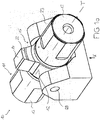
- the device 10 shown for welding components by means of ultrasound contains a sonotrode 11 with two end pieces 13 and a sonotrode head 12 arranged between them, which can be excited by means of vibration generators (not shown here) via the end pieces 13 to torsion vibrations with respect to a torsion axis T.
- the sonotrode head 12 has two projections 22 which are radial and opposite one another with respect to the torsion axis T. At the ends of the projections 22 a welding surface 14 is formed, with which a first component can be connected to a second component by welding. Both welding surfaces 14 are therefore arranged on the circumferential side with respect to the torsion axis T.
- the device 10 further includes a support device 15 which supports the sonotrode head 12 in a support area. This support area, which in Figure 1b is shown in more detail, contains a vibration node of the sonotrode head 12.
- the sectional view according to Figure 1b shows details of the support device 15.
- the sonotrode 11 has a cylindrical bore 17 which penetrates the support area 16 perpendicular to the torsion axis T and also perpendicular to a connecting line V connecting the two welding surfaces 14 to one another.
- the support device 15 further includes, and according to the invention, one extending through the bore 17 Support bolt 18, the central region 24 of which supports the sonotrode 11 in the support region 16 in the bore 17.
- the support pin 18 widens in the direction of its central area 24. In the exemplary embodiment shown here, the length of the support area 16 along the support pin 18 is approximately 20% of the extent of the sonotrode head 12 along the support pin 18.
- the support pin 18 is pressed into the bore 17 in the sonotrode 11 held. This can be achieved, for example, by cold shrinking, in which the support pin 18 is shrunk by cooling and is then inserted into the bore 17 through the bearing openings 29. During the subsequent reheating, the support pin 18 is pressed into the bore.
- the sonotrode 11 according to the invention is supported only in an area of the sonotrode head 12 that is inner with respect to the torsion axis T.
- the support region 16 forms only an inner region of the sonotrode head 12 with respect to the torsion axis T.
- the support region 16 and the welding surface 14 run in a common plane E, which extends perpendicular to the torsion axis T.
- the position of the vibration node practically does not depend on the forces or torques acting on the welding surfaces 14. Irrespective of these forces or torques, there is no significant decoupling of the ultrasound energy via the support device 15, so that a larger proportion of the ultrasound energy is available for the actual purpose of welding.
- the support pin 18 is designed in this embodiment as a hollow pin 18. Alternatively, the support pin 18 can also consist of solid material.
- the support pin 18 has two opposite ends 20 which are each received in a bearing opening 29 of a bearing bush 21 of a common, one-piece bearing block 23. In this way, forces and torques can be transferred to the bearing block.
- the support pin 18 permits particularly precise positioning of the sonotrode head 12.
- the device 10 can also contain a pressure device, not shown here, for generating forces K acting perpendicular to the torsion axis T on the bearing block 23. In this way, one of the welding surfaces 14 can be pressed against a first component which is to be connected to a second component.
- FIGS. 2a to 2e show a second device 10 'according to the invention for welding components by means of ultrasound.
- the device 10 contains a bearing block 26' with a groove-shaped recess in which a sonotrode 11 'is received.
- This sonotrode 11 ' also contains two end pieces 13' with an interposed sonotrode head 12 'with two projections 22', each of which has a welding surface 14 'at its ends. Via the end pieces 13 ', the sonotrode head 12' can be excited to torsion vibrations with respect to a torsion axis T by means of two vibration generators (not shown).
- Two opposite ends 20 'of a support bolt 18' are fastened to the bearing block 26 'with the aid of clamping claws 27'.
- the clamping claws 27 ' are fixed to the bearing block 26' by means of screws which are inserted into screw openings 28 '. By releasing the clamping claws 27 'from the bearing block 26', the support pin 18 'is particularly easily accessible.
- a pressure device not shown here, for example a pneumatic cylinder, forces K acting perpendicular to the torsion axis T can be exerted on the bearing block 26 ', as a result of which the Welding surface 14 'can be pressed against a first component to be connected to a second component.
- the device 10 contains two supports 30' with which the end pieces 13 'of the sonotrode 11' are held.
- These two supports 30 ' can consist of hard tissue panels, for example. They also contain a trough-shaped depression for supporting the end pieces 13 '. With the help of the supports 30 ', the position of the sonotrode 11' can be adjusted particularly precisely.
- the sonotrode 11 ' has a bore 17' which intersects the torsion axis T and thereby penetrates the sonotrode head 12 'perpendicular to the torsion axis T and also perpendicular to a connecting line V connecting the two projections 22'.
- a support pin 18 ' is inserted into the bore 17' and supports the sonotrode 11 'in a support region 16' in the bore 17 '.
- the support pin 18 ' is held by a transition fit so that it can be replaced if necessary, for example if it is worn, bent or broken.
- An oscillation node of the sonotrode head 12 ' is present in the support region 16'.
- Figure 2d shows a detailed perspective sectional view of the sonotrode head 12 '.
- the bore 17 'in the support region 16' has a first inner diameter, and in two opposite mouth sections 19 'it has a second inner diameter which is larger than the first inner diameter.
- the bore 17 'tapers in the direction of the support region 16'.
- the support pin 18 ' is shown in detail. In contrast to the support pin 18 of the first embodiment this support pin 18 'made of a solid material.
- the support pin 18 ' contains a central region 24' with a first outer diameter and two opposite end regions 25 'with a second outer diameter which is smaller than the first outer diameter.
- the support pin 18 'thus widens in the direction of the central region in which it supports the sonotrode head 12'.
- the length of the support region 16 'along the support bolt 18' is approximately 25% of the extent of the sonotrode head 12 'along the support bolt 18'.
- the sonotrode head 12 ′ is thereby supported only in an area of the sonotrode head 12 ′ that is inner with respect to the torsion axis T. Furthermore, the support region 16 ′ and the two welding surfaces 14 ′ run in a common plane E, which extends perpendicular to the torsion axis T.
- the clamping claws 27' can first be released from the bearing block 26 '. Due to the centering of the bore 17 'and the support bolt 18' and due to the overall symmetrical arrangement, the sonotrode 11 'can then simply be rotated together with the support bolt 18' by 180 ° about the torsion axis T, so that the ends 20 'in the Bearing openings 29 'are added. The clamping claws 27 'can then be fastened again to the bearing block 26'. This positioning is extremely precise due to the support bolt 18 '.
- the third device 10 "according to the invention is shown in comparison to that shown in FIGS Figures 2a to 2e shown device 10 'of the support bolt as a hollow bolt 18 ". It has a centered and continuously cylindrical Channel 31 "through which a temperature control fluid, in particular a cooling medium or a heating medium, for example water, can be introduced, passed through and executed again in the sonotrode head 12". In this way, temperature control, in particular cooling or heating, of the sonotrode head 12 "in the area of the welding surfaces 14" can be achieved.
- the channel 31 ′′ opens out at openings 32 ′′, 33 ′′ which are arranged at opposite ends 20 ′′ of the support bolt 18 ′′.
- the temperature control fluid can be introduced through a first opening 32 ′′ and again from a second opening 33 ′′
- this embodiment allows the sonotrode 11 "to be cooled in the area of the welding surfaces 14" where most of the heat is generated during welding.
- FIG 4 schematically shows a fourth exemplary embodiment according to the invention, in which a welding surface 14 '''is arranged on an end surface of the sonotrode head 12'''.
- the ends 20 '''of the support bolt 18''' are held in two bearing openings, not shown here.
- temperature control channels are also provided in the area of the welding surface 14''' and are fluid-connected to the feed channel 31 '''. In this way, the sonotrode head 11 '''can be cooled in the area of the welding surface 14'''.
- the sonotrode head 12 ''' can cause torsional vibrations with respect to a torsion axis T or longitudinal vibrations be excitable, wherein the support region 16 '''contains a torsional or longitudinal vibration node of the sonotrode head 12'''. Due to the arrangement of the support bolt 18 '''in this area, the supply of the temperature control fluid is not impaired.
Landscapes
- Engineering & Computer Science (AREA)
- Mechanical Engineering (AREA)
- Lining Or Joining Of Plastics Or The Like (AREA)
- Pressure Welding/Diffusion-Bonding (AREA)
- Apparatuses For Generation Of Mechanical Vibrations (AREA)
Claims (14)
- Dispositif (10 ; 10' ; 10") de soudage de pièces par ultrasons, comportant- une sonotrode (11 ; 11' ; 11") dotée d'une tête de sonotrode (12 ; 12' ; 12"), laquelle peut être excitée par un générateur de vibrations pour produire des vibrations torsionnelles par rapport à un axe de torsion (T), au moins une surface de soudage (14 ; 14' ; 14") étant disposée sur la tête de sonotrode (12 ; 12' ; 12") du côté périphérique par rapport à l'axe de torsion (T),- un dispositif de support (15 ; 15' ; 15"), lequel supporte la tête de sonotrode (11 ; 11' ; 11") dans une région de support (16 ; 16' ; 16'') qui contient un nœud de vibration de la tête de sonotrode (12 ; 12' ; 12"),caractérisé en ce que- la sonotrode (11 ; 11' ; 11" ; 11''') comprend un alésage (17 ; 17' ; 17" ; 17'''), lequel traverse la région de support (16 ; 16' ; 16" ; 16''') sensiblement perpendiculairement à l'axe de torsion (T),- le dispositif de support (15 ; 15' ; 15" ; 15''') comporte un axe de support (18 ; 18' ; 18" ; 18''') s'étendant à travers l'alésage (17 ; 17' ; 17" ; 17'''), lequel axe de support supporte la sonotrode (11 ; 11' ; 11", 11''') dans la région de support (16 ; 16' ; 16" ; 16''') dans l'alésage (17 ; 17' ; 17" ; 17'''),- la région de support (16 ; 16' ; 16") et la surface de soudage (14 ; 14' ; 14") s'étendent au moins partiellement dans un plan commun (E) qui s'étend perpendiculairement à l'axe de torsion (T), et- la région de support (16 ; 16' ; 16") forme seulement une région, intérieure par rapport à l'axe de torsion (T), de la tête de sonotrode (12 ; 12' ; 12").
- Dispositif (10 ; 10' ; 10" ; 10''') selon la revendication 1,
caractérisé en ce que
l'axe de support (18 ; 18' ; 18" ; 18''') supporte la sonotrode (11 ; 11' ; 11" ; 11''') dans la région de support (16 ; 16' ; 16" ; 16''') dans l'alésage (17 ; 17' ; 17" ; 17''') par le biais d'un ajustement de transition, d'un retrait ou d'un enfoncement. - Dispositif (10 ; 10' ; 10" ; 10''') selon la revendication 1 ou 2,
caractérisé en ce que
l'axe de support (18 ; 18' ; 18" ; 18''') croise l'axe de torsion (T) . - Dispositif (10 ; 10' ; 10") selon l'une des revendications 1 à 3,
caractérisé en ce que
l'alésage (17 ; 17' ; 17") se rétrécit dans la direction de la région de support (16 ; 16' ; 16"). - Dispositif (10 ; 10' ; 10") selon l'une des revendications 1 à 4,
caractérisé en ce que
l'axe de support (18 ; 18' ; 18") s'élargit dans la direction d'une région centrale (24 ; 24' ; 24") dans laquelle l'axe de support (18 ; 18' ; 18") supporte la tête de sonotrode (11 ; 11' ; 11"). - Dispositif (10 ; 10', 10") selon l'une des revendications 1 à 5,
caractérisé en ce que
la longueur de la région de support (16 ; 16' ; 16") le long de l'axe de support (18 ; 18' ; 18") est comprise entre 10 % et 30 %, de préférence entre 20 % et 25 % de l'étendue de la tête de sonotrode (12 ; 12' ; 12") le long de l'axe de support (18 ; 18' ; 18"). - Dispositif (10 ; 10' ; 10") selon l'une des revendications 1 à 6,
caractérisé en ce que
l'axe de support (18 ; 18' ; 18") comprend deux extrémités opposées (20 ; 20' ; 20") qui sont logées dans respectivement une ouverture de palier (29 ; 29' ; 29"). - Dispositif (10 ; 10' ; 10") selon la revendication 7,
caractérisé en ce
qu'il comporte un bloc de palier (23 ; 26' ; 26") en particulier d'un seul tenant, lequel forme au moins partiellement les deux ouvertures de palier (29 ; 29' ; 29"). - Dispositif (10 ; 10' ; 10") selon la revendication 8,
caractérisé en ce
qu'il comporte un dispositif de pression servant à produire des forces (K) agissant sensiblement perpendiculairement à l'axe de torsion (T) sur le bloc de palier (23 ; 26' ; 26"), de sorte que la surface de soudage (14 ; 14' ; 14") puisse être pressée contre une première pièce à relier à une deuxième pièce. - Dispositif (10" ; 10''') selon l'une des revendications précédentes,
caractérisé en ce que
le dispositif de support (15" ; 15''') comprend un dispositif de thermorégulation pour la thermorégulation, en particulier pour refroidir ou pour chauffer la tête de sonotrode (12", 12'''), le dispositif de thermorégulation comportant au moins une amenée de thermorégulation guidée à travers le dispositif de support (15" ; 15''') pour un milieu de thermorégulation et au moins un élément de thermorégulation relié fonctionnellement à l'amenée de thermorégulation, lequel est disposé de préférence dans la région d'une surface de soudage (14" ; 14''') de la tête de sonotrode (12", 12'''). - Dispositif (10" ; 10''') selon la revendication 10,
caractérisé en ce que
l'amenée de thermorégulation comporte au moins un canal d'amenée (31" ; 31'''), au moyen duquel un fluide de thermorégulation peut être introduit dans la tête de sonotrode (12", 12''') ou peut être évacué de la tête de sonotrode (12", 12'''), et l'élément de thermorégulation comporte au moins un canal de thermorégulation pour le fluide de thermorégulation, lequel canal de thermorégulation est relié fluidiquement au canal d'amenée (31" ; 31'''). - Dispositif (10" ; 10''') selon la revendication 11,
caractérisé en ce que
l'axe de support (18" ; 18''') comprend le canal d'amenée (31" ; 31''') et le canal d'amenée (31" ; 31''') débouche au niveau d'ouvertures (32", 33") qui sont disposées à des extrémités opposées (20" ; 20''') de l'axe de support (18" ; 18'''). - Dispositif (10 ; 10' ; 10") selon l'une des revendications précédentes,
caractérisé en ce que
la tête de sonotrode (12 ; 12' ; 12") peut être excitée par un générateur de vibrations pour produire des vibrations torsionnelles par rapport à un axe de torsion (T) et la tête de sonotrode (12 ; 12' ; 12") comprend au moins une, de préférence plusieurs, saillies (22 ; 22' ; 22") radiales par rapport à l'axe de torsion (T), aux extrémités desquelles est formée respectivement une surface de soudage (14 ; 14' ; 14"). - Dispositif (10 ; 10', 10") selon l'une des revendications 1 à 13,
caractérisé en ce que
la tête de sonotrode (12 ; 12' ; 12") peut être excitée par un générateur de vibrations pour produire des vibrations torsionnelles par rapport à un axe de torsion (T) et la tête de sonotrode (12 ; 12' ; 12") comprend exactement deux saillies (22 ; 22' ; 22") radiales et opposées l'une à l'autre par rapport à l'axe de torsion (T), aux extrémités desquelles est formée respectivement une surface de soudage (14 ; 14' ; 14"), l'axe de support (18 ; 18' ; 18") s'étendant sensiblement perpendiculairement à une ligne de liaison (V) qui relie l'une à l'autre les deux surfaces de soudage (14 ; 14' ; 14").
Applications Claiming Priority (2)
| Application Number | Priority Date | Filing Date | Title |
|---|---|---|---|
| PCT/EP2015/064889 WO2017000998A1 (fr) | 2015-06-30 | 2015-06-30 | Dispositif pour souder des pièces au moyen d'ultrasons par des oscillations de torsion |
| PCT/EP2016/064360 WO2017001255A2 (fr) | 2015-06-30 | 2016-06-22 | Dispositif pour la soudure de composants au moyen d'ultrasons |
Publications (2)
| Publication Number | Publication Date |
|---|---|
| EP3317040A2 EP3317040A2 (fr) | 2018-05-09 |
| EP3317040B1 true EP3317040B1 (fr) | 2020-01-29 |
Family
ID=53673907
Family Applications (1)
| Application Number | Title | Priority Date | Filing Date |
|---|---|---|---|
| EP16736803.4A Active EP3317040B1 (fr) | 2015-06-30 | 2016-06-22 | Dispositif pour la soudure de composants au moyen d'ultrasons |
Country Status (6)
| Country | Link |
|---|---|
| US (2) | US10532424B2 (fr) |
| EP (1) | EP3317040B1 (fr) |
| JP (1) | JP6983667B2 (fr) |
| KR (1) | KR102495445B1 (fr) |
| CN (1) | CN108025388B (fr) |
| WO (2) | WO2017000998A1 (fr) |
Families Citing this family (8)
| Publication number | Priority date | Publication date | Assignee | Title |
|---|---|---|---|---|
| WO2018145769A1 (fr) | 2017-02-13 | 2018-08-16 | Telsonic Holding Ag | Système de traitement par ultrasons, amplificateur et méthode |
| DE112017007837A5 (de) | 2017-10-25 | 2020-05-07 | Telsonic Holding Ag | Vorrichtung zum Bearbeiten von Bauteilen mittels Ultraschalls |
| WO2021089155A1 (fr) | 2019-11-07 | 2021-05-14 | Schunk Sonosystems Gmbh | Appareil de soudage par ultrasons avec refroidissement pour arrangement d'oscillateur |
| EP3936273B1 (fr) | 2020-07-06 | 2024-11-13 | Telsonic Holding AG | Dispositif et procédé de soudage par ultrasons |
| CN112355459A (zh) * | 2020-10-30 | 2021-02-12 | 上海骄成机电设备有限公司 | 超声波组件及超声波焊机 |
| CN113618226A (zh) | 2020-11-26 | 2021-11-09 | 上海骄成超声波技术股份有限公司 | 一种焊头组件 |
| JP7638684B2 (ja) | 2020-11-27 | 2025-03-04 | キヤノン株式会社 | 溶着方法、液体吐出ヘッドの製造方法、液体吐出ヘッドおよび液体吐出ヘッドの製造装置 |
| CN114054928B (zh) * | 2021-12-23 | 2023-07-04 | 亚洲硅业(青海)股份有限公司 | 一种硅芯焊接装置及硅芯焊接方法 |
Family Cites Families (19)
| Publication number | Priority date | Publication date | Assignee | Title |
|---|---|---|---|---|
| US3184841A (en) | 1958-06-03 | 1965-05-25 | Sonobond Corp | Method and apparatus employing vibratory energy for bonding metals |
| US3602420A (en) * | 1970-02-12 | 1971-08-31 | Ibm | Ultrasonic bonding device |
| DE10101236A1 (de) | 2001-01-12 | 2002-07-25 | Schunk Ultraschalltechnik Gmbh | Verfahren und Vorrichtung zum Verbinden von Leitern |
| JP3466175B2 (ja) * | 2001-12-03 | 2003-11-10 | 三島 大二 | 超音波振動ホーン |
| JP3952959B2 (ja) * | 2002-02-25 | 2007-08-01 | 株式会社村田製作所 | 超音波ホーンおよびこの超音波ホーンを用いた超音波接合装置 |
| JP4056276B2 (ja) * | 2002-03-27 | 2008-03-05 | 松下電器産業株式会社 | 部品実装方法及び装置 |
| DE10250741B4 (de) | 2002-10-31 | 2004-08-26 | Kunststoff-Zentrum in Leipzig gemeinnützige Gesellschaft mbH | Beheiztes Schwingwerkzeug zum Einsatz in schwingenden Systemen |
| US7002283B2 (en) * | 2003-06-03 | 2006-02-21 | Asm Assembly Automation Ltd. | Ultrasonic transducer assembly |
| EP1930148A1 (fr) * | 2006-12-07 | 2008-06-11 | Telsonic Holding AG | Utilisation d'un dispositif destiné à la soudure par ultrasons torsionnelle |
| JP2008142738A (ja) * | 2006-12-08 | 2008-06-26 | Nissan Motor Co Ltd | 超音波接合装置およびその制御方法 |
| WO2009154658A1 (fr) * | 2008-02-22 | 2009-12-23 | Piezolnnovations | Systèmes de transducteurs à mode ultrasonore torsionnel et longitudinal-torsionnel |
| DE202008007271U1 (de) | 2008-05-27 | 2008-07-31 | Stemke, Gudrun | Sonotrode |
| EP2261008A1 (fr) | 2009-06-08 | 2010-12-15 | Telsonic Holding AG | Procédé et dispositif de traitement par ultrasons |
| WO2011003891A1 (fr) * | 2009-07-06 | 2011-01-13 | Faurecia Exteriors Gmbh | Elément rapporté à relier à une pièce par soudage par ultrasons de torsion |
| DE102010029395A1 (de) | 2010-05-07 | 2011-11-10 | Telsonic Holding Ag | Torsionssonotrode, Ultraschall-Schweißvorrichtung und Verfahren zur Herstellung einer Schweißverbindung mittels Ultraschall |
| EP2457683A1 (fr) | 2010-11-25 | 2012-05-30 | Telsonic Holding AG | Soudage torsionnel |
| DE202013100866U1 (de) | 2012-05-18 | 2013-03-13 | Maschinenfabrik Gerd Mosca Ag | Ultraschall-Schweißvorrichtung mit Sonotrode |
| US8858742B2 (en) * | 2012-11-16 | 2014-10-14 | GM Global Technology Operations LLC | Automatic monitoring of vibration welding equipment |
| DE102013215106A1 (de) * | 2013-08-01 | 2015-02-05 | PP-Tech GmbH | Sonotrodenwerkzeug mit integrierter Kühleinrichtung |
-
2015
- 2015-06-30 WO PCT/EP2015/064889 patent/WO2017000998A1/fr not_active Ceased
-
2016
- 2016-06-22 WO PCT/EP2016/064360 patent/WO2017001255A2/fr not_active Ceased
- 2016-06-22 US US15/740,191 patent/US10532424B2/en active Active
- 2016-06-22 JP JP2017567417A patent/JP6983667B2/ja active Active
- 2016-06-22 KR KR1020187002824A patent/KR102495445B1/ko active Active
- 2016-06-22 CN CN201680039196.2A patent/CN108025388B/zh active Active
- 2016-06-22 EP EP16736803.4A patent/EP3317040B1/fr active Active
-
2019
- 2019-12-02 US US16/700,349 patent/US11247294B2/en not_active Expired - Fee Related
Non-Patent Citations (1)
| Title |
|---|
| None * |
Also Published As
| Publication number | Publication date |
|---|---|
| CN108025388A (zh) | 2018-05-11 |
| KR102495445B1 (ko) | 2023-02-02 |
| JP2018527187A (ja) | 2018-09-20 |
| WO2017001255A3 (fr) | 2017-02-23 |
| US10532424B2 (en) | 2020-01-14 |
| WO2017000998A1 (fr) | 2017-01-05 |
| WO2017001255A2 (fr) | 2017-01-05 |
| US11247294B2 (en) | 2022-02-15 |
| JP6983667B2 (ja) | 2021-12-17 |
| CN108025388B (zh) | 2020-03-13 |
| US20200171598A1 (en) | 2020-06-04 |
| EP3317040A2 (fr) | 2018-05-09 |
| KR20180020301A (ko) | 2018-02-27 |
| US20180185956A1 (en) | 2018-07-05 |
Similar Documents
| Publication | Publication Date | Title |
|---|---|---|
| EP3317040B1 (fr) | Dispositif pour la soudure de composants au moyen d'ultrasons | |
| EP2288450B1 (fr) | Sonotrode pour une unité émettrice d'ultrasons | |
| DE19758583C2 (de) | Vorrichtung zum Bruchtrennen eines ringförmigen Bauteils | |
| EP2442964B1 (fr) | Dispositif de traitement par ultrasons, et sonotrode pour scellage transversal correspondante | |
| EP1321210B1 (fr) | Outil de chanfreinage | |
| EP3362212B1 (fr) | Outil d'usinage par enlèvement de copeaux | |
| EP3898057A1 (fr) | Installation de soudage par ultrasons à élément d'appui | |
| WO2020126831A1 (fr) | Système de soudage par ultrasons | |
| EP3822018A1 (fr) | Composant à ultrasons, dispositif d'usinage des pièces et procédé d'usinage des pièces | |
| EP3275597B1 (fr) | Outil et procédé de montage et démontage de composants | |
| EP2995417B1 (fr) | Dispositif de montage d'au moins un element fonctionnel presentant un evidement pour un arbre | |
| EP0972613A1 (fr) | Toc d'entraínement pour machine outil | |
| EP2177296A1 (fr) | Dispositif de serrage extensible | |
| EP2686155B1 (fr) | Sonotrode présentant un canal de traitement | |
| WO2018011129A1 (fr) | Dispositif de soudage par ultrasons et sonotrode destinée à un tel dispositif | |
| EP1453657B1 (fr) | Sonotrode pour effectuer des operations de coupe et de soudage sur des pieces | |
| EP3269492A1 (fr) | Dispositif de soudure par ultrasons et sonotrodes pour un tel dispositif | |
| EP3335807A1 (fr) | Sonotrode et unité oscillante pourvue d'une telle sonotrode | |
| DE19733387A1 (de) | Vorrichtung zum Bruchtrennen eines ringförmigen Bauteils | |
| DE10137055A1 (de) | Kupplungsvorrichtung für das Verbinden einer Spindel mit einem Werkzeughalter | |
| EP3536436B1 (fr) | Dispositif et procédé de raccordement de pièces à usiner | |
| CH671530A5 (en) | Ultrasonic machining tool for milling or boring applications - has tool crown subjected to both axial and radial oscillations | |
| EP3299089B1 (fr) | Unité de sonotrode ainsi que son procédé de fabrication | |
| EP1839790B1 (fr) | Dispositif et procédé destinés à la division par rupture de bielles | |
| EP3672769A1 (fr) | Procédé de découpe d'une bande en caoutchouc |
Legal Events
| Date | Code | Title | Description |
|---|---|---|---|
| STAA | Information on the status of an ep patent application or granted ep patent |
Free format text: STATUS: THE INTERNATIONAL PUBLICATION HAS BEEN MADE |
|
| PUAI | Public reference made under article 153(3) epc to a published international application that has entered the european phase |
Free format text: ORIGINAL CODE: 0009012 |
|
| STAA | Information on the status of an ep patent application or granted ep patent |
Free format text: STATUS: REQUEST FOR EXAMINATION WAS MADE |
|
| 17P | Request for examination filed |
Effective date: 20171222 |
|
| AK | Designated contracting states |
Kind code of ref document: A2 Designated state(s): AL AT BE BG CH CY CZ DE DK EE ES FI FR GB GR HR HU IE IS IT LI LT LU LV MC MK MT NL NO PL PT RO RS SE SI SK SM TR |
|
| AX | Request for extension of the european patent |
Extension state: BA ME |
|
| DAX | Request for extension of the european patent (deleted) | ||
| RAV | Requested validation state of the european patent: fee paid |
Extension state: MA Effective date: 20171222 |
|
| STAA | Information on the status of an ep patent application or granted ep patent |
Free format text: STATUS: EXAMINATION IS IN PROGRESS |
|
| 17Q | First examination report despatched |
Effective date: 20190212 |
|
| GRAP | Despatch of communication of intention to grant a patent |
Free format text: ORIGINAL CODE: EPIDOSNIGR1 |
|
| STAA | Information on the status of an ep patent application or granted ep patent |
Free format text: STATUS: GRANT OF PATENT IS INTENDED |
|
| INTG | Intention to grant announced |
Effective date: 20191023 |
|
| GRAS | Grant fee paid |
Free format text: ORIGINAL CODE: EPIDOSNIGR3 |
|
| GRAA | (expected) grant |
Free format text: ORIGINAL CODE: 0009210 |
|
| STAA | Information on the status of an ep patent application or granted ep patent |
Free format text: STATUS: THE PATENT HAS BEEN GRANTED |
|
| AK | Designated contracting states |
Kind code of ref document: B1 Designated state(s): AL AT BE BG CH CY CZ DE DK EE ES FI FR GB GR HR HU IE IS IT LI LT LU LV MC MK MT NL NO PL PT RO RS SE SI SK SM TR |
|
| REG | Reference to a national code |
Ref country code: GB Ref legal event code: FG4D Free format text: NOT ENGLISH |
|
| REG | Reference to a national code |
Ref country code: CH Ref legal event code: EP |
|
| REG | Reference to a national code |
Ref country code: AT Ref legal event code: REF Ref document number: 1228132 Country of ref document: AT Kind code of ref document: T Effective date: 20200215 |
|
| REG | Reference to a national code |
Ref country code: IE Ref legal event code: FG4D Free format text: LANGUAGE OF EP DOCUMENT: GERMAN |
|
| REG | Reference to a national code |
Ref country code: DE Ref legal event code: R096 Ref document number: 502016008545 Country of ref document: DE |
|
| REG | Reference to a national code |
Ref country code: NL Ref legal event code: MP Effective date: 20200129 |
|
| PG25 | Lapsed in a contracting state [announced via postgrant information from national office to epo] |
Ref country code: NO Free format text: LAPSE BECAUSE OF FAILURE TO SUBMIT A TRANSLATION OF THE DESCRIPTION OR TO PAY THE FEE WITHIN THE PRESCRIBED TIME-LIMIT Effective date: 20200429 Ref country code: FI Free format text: LAPSE BECAUSE OF FAILURE TO SUBMIT A TRANSLATION OF THE DESCRIPTION OR TO PAY THE FEE WITHIN THE PRESCRIBED TIME-LIMIT Effective date: 20200129 Ref country code: RS Free format text: LAPSE BECAUSE OF FAILURE TO SUBMIT A TRANSLATION OF THE DESCRIPTION OR TO PAY THE FEE WITHIN THE PRESCRIBED TIME-LIMIT Effective date: 20200129 Ref country code: PT Free format text: LAPSE BECAUSE OF FAILURE TO SUBMIT A TRANSLATION OF THE DESCRIPTION OR TO PAY THE FEE WITHIN THE PRESCRIBED TIME-LIMIT Effective date: 20200621 |
|
| REG | Reference to a national code |
Ref country code: LT Ref legal event code: MG4D |
|
| PG25 | Lapsed in a contracting state [announced via postgrant information from national office to epo] |
Ref country code: HR Free format text: LAPSE BECAUSE OF FAILURE TO SUBMIT A TRANSLATION OF THE DESCRIPTION OR TO PAY THE FEE WITHIN THE PRESCRIBED TIME-LIMIT Effective date: 20200129 Ref country code: BG Free format text: LAPSE BECAUSE OF FAILURE TO SUBMIT A TRANSLATION OF THE DESCRIPTION OR TO PAY THE FEE WITHIN THE PRESCRIBED TIME-LIMIT Effective date: 20200429 Ref country code: SE Free format text: LAPSE BECAUSE OF FAILURE TO SUBMIT A TRANSLATION OF THE DESCRIPTION OR TO PAY THE FEE WITHIN THE PRESCRIBED TIME-LIMIT Effective date: 20200129 Ref country code: LV Free format text: LAPSE BECAUSE OF FAILURE TO SUBMIT A TRANSLATION OF THE DESCRIPTION OR TO PAY THE FEE WITHIN THE PRESCRIBED TIME-LIMIT Effective date: 20200129 Ref country code: IS Free format text: LAPSE BECAUSE OF FAILURE TO SUBMIT A TRANSLATION OF THE DESCRIPTION OR TO PAY THE FEE WITHIN THE PRESCRIBED TIME-LIMIT Effective date: 20200529 Ref country code: GR Free format text: LAPSE BECAUSE OF FAILURE TO SUBMIT A TRANSLATION OF THE DESCRIPTION OR TO PAY THE FEE WITHIN THE PRESCRIBED TIME-LIMIT Effective date: 20200430 |
|
| PG25 | Lapsed in a contracting state [announced via postgrant information from national office to epo] |
Ref country code: NL Free format text: LAPSE BECAUSE OF FAILURE TO SUBMIT A TRANSLATION OF THE DESCRIPTION OR TO PAY THE FEE WITHIN THE PRESCRIBED TIME-LIMIT Effective date: 20200129 |
|
| PG25 | Lapsed in a contracting state [announced via postgrant information from national office to epo] |
Ref country code: CZ Free format text: LAPSE BECAUSE OF FAILURE TO SUBMIT A TRANSLATION OF THE DESCRIPTION OR TO PAY THE FEE WITHIN THE PRESCRIBED TIME-LIMIT Effective date: 20200129 Ref country code: RO Free format text: LAPSE BECAUSE OF FAILURE TO SUBMIT A TRANSLATION OF THE DESCRIPTION OR TO PAY THE FEE WITHIN THE PRESCRIBED TIME-LIMIT Effective date: 20200129 Ref country code: SK Free format text: LAPSE BECAUSE OF FAILURE TO SUBMIT A TRANSLATION OF THE DESCRIPTION OR TO PAY THE FEE WITHIN THE PRESCRIBED TIME-LIMIT Effective date: 20200129 Ref country code: ES Free format text: LAPSE BECAUSE OF FAILURE TO SUBMIT A TRANSLATION OF THE DESCRIPTION OR TO PAY THE FEE WITHIN THE PRESCRIBED TIME-LIMIT Effective date: 20200129 Ref country code: EE Free format text: LAPSE BECAUSE OF FAILURE TO SUBMIT A TRANSLATION OF THE DESCRIPTION OR TO PAY THE FEE WITHIN THE PRESCRIBED TIME-LIMIT Effective date: 20200129 Ref country code: LT Free format text: LAPSE BECAUSE OF FAILURE TO SUBMIT A TRANSLATION OF THE DESCRIPTION OR TO PAY THE FEE WITHIN THE PRESCRIBED TIME-LIMIT Effective date: 20200129 Ref country code: DK Free format text: LAPSE BECAUSE OF FAILURE TO SUBMIT A TRANSLATION OF THE DESCRIPTION OR TO PAY THE FEE WITHIN THE PRESCRIBED TIME-LIMIT Effective date: 20200129 Ref country code: SM Free format text: LAPSE BECAUSE OF FAILURE TO SUBMIT A TRANSLATION OF THE DESCRIPTION OR TO PAY THE FEE WITHIN THE PRESCRIBED TIME-LIMIT Effective date: 20200129 |
|
| REG | Reference to a national code |
Ref country code: DE Ref legal event code: R097 Ref document number: 502016008545 Country of ref document: DE |
|
| PLBE | No opposition filed within time limit |
Free format text: ORIGINAL CODE: 0009261 |
|
| STAA | Information on the status of an ep patent application or granted ep patent |
Free format text: STATUS: NO OPPOSITION FILED WITHIN TIME LIMIT |
|
| 26N | No opposition filed |
Effective date: 20201030 |
|
| PG25 | Lapsed in a contracting state [announced via postgrant information from national office to epo] |
Ref country code: MC Free format text: LAPSE BECAUSE OF FAILURE TO SUBMIT A TRANSLATION OF THE DESCRIPTION OR TO PAY THE FEE WITHIN THE PRESCRIBED TIME-LIMIT Effective date: 20200129 Ref country code: IT Free format text: LAPSE BECAUSE OF FAILURE TO SUBMIT A TRANSLATION OF THE DESCRIPTION OR TO PAY THE FEE WITHIN THE PRESCRIBED TIME-LIMIT Effective date: 20200129 |
|
| REG | Reference to a national code |
Ref country code: CH Ref legal event code: PL |
|
| PG25 | Lapsed in a contracting state [announced via postgrant information from national office to epo] |
Ref country code: PL Free format text: LAPSE BECAUSE OF FAILURE TO SUBMIT A TRANSLATION OF THE DESCRIPTION OR TO PAY THE FEE WITHIN THE PRESCRIBED TIME-LIMIT Effective date: 20200129 Ref country code: SI Free format text: LAPSE BECAUSE OF FAILURE TO SUBMIT A TRANSLATION OF THE DESCRIPTION OR TO PAY THE FEE WITHIN THE PRESCRIBED TIME-LIMIT Effective date: 20200129 |
|
| GBPC | Gb: european patent ceased through non-payment of renewal fee |
Effective date: 20200622 |
|
| PG25 | Lapsed in a contracting state [announced via postgrant information from national office to epo] |
Ref country code: LU Free format text: LAPSE BECAUSE OF NON-PAYMENT OF DUE FEES Effective date: 20200622 |
|
| REG | Reference to a national code |
Ref country code: BE Ref legal event code: MM Effective date: 20200630 |
|
| PG25 | Lapsed in a contracting state [announced via postgrant information from national office to epo] |
Ref country code: CH Free format text: LAPSE BECAUSE OF NON-PAYMENT OF DUE FEES Effective date: 20200630 Ref country code: LI Free format text: LAPSE BECAUSE OF NON-PAYMENT OF DUE FEES Effective date: 20200630 Ref country code: IE Free format text: LAPSE BECAUSE OF NON-PAYMENT OF DUE FEES Effective date: 20200622 Ref country code: GB Free format text: LAPSE BECAUSE OF NON-PAYMENT OF DUE FEES Effective date: 20200622 Ref country code: FR Free format text: LAPSE BECAUSE OF NON-PAYMENT OF DUE FEES Effective date: 20200630 |
|
| PG25 | Lapsed in a contracting state [announced via postgrant information from national office to epo] |
Ref country code: BE Free format text: LAPSE BECAUSE OF NON-PAYMENT OF DUE FEES Effective date: 20200630 |
|
| VS25 | Lapsed in a validation state [announced via postgrant information from nat. office to epo] |
Ref country code: MA Free format text: LAPSE BECAUSE OF FAILURE TO SUBMIT A TRANSLATION OF THE DESCRIPTION OR TO PAY THE FEE WITHIN THE PRESCRIBED TIME-LIMIT Effective date: 20200129 |
|
| PG25 | Lapsed in a contracting state [announced via postgrant information from national office to epo] |
Ref country code: TR Free format text: LAPSE BECAUSE OF FAILURE TO SUBMIT A TRANSLATION OF THE DESCRIPTION OR TO PAY THE FEE WITHIN THE PRESCRIBED TIME-LIMIT Effective date: 20200129 Ref country code: MT Free format text: LAPSE BECAUSE OF FAILURE TO SUBMIT A TRANSLATION OF THE DESCRIPTION OR TO PAY THE FEE WITHIN THE PRESCRIBED TIME-LIMIT Effective date: 20200129 Ref country code: CY Free format text: LAPSE BECAUSE OF FAILURE TO SUBMIT A TRANSLATION OF THE DESCRIPTION OR TO PAY THE FEE WITHIN THE PRESCRIBED TIME-LIMIT Effective date: 20200129 |
|
| PG25 | Lapsed in a contracting state [announced via postgrant information from national office to epo] |
Ref country code: MK Free format text: LAPSE BECAUSE OF FAILURE TO SUBMIT A TRANSLATION OF THE DESCRIPTION OR TO PAY THE FEE WITHIN THE PRESCRIBED TIME-LIMIT Effective date: 20200129 Ref country code: AL Free format text: LAPSE BECAUSE OF FAILURE TO SUBMIT A TRANSLATION OF THE DESCRIPTION OR TO PAY THE FEE WITHIN THE PRESCRIBED TIME-LIMIT Effective date: 20200129 |
|
| REG | Reference to a national code |
Ref country code: AT Ref legal event code: MM01 Ref document number: 1228132 Country of ref document: AT Kind code of ref document: T Effective date: 20210622 |
|
| PG25 | Lapsed in a contracting state [announced via postgrant information from national office to epo] |
Ref country code: AT Free format text: LAPSE BECAUSE OF NON-PAYMENT OF DUE FEES Effective date: 20210622 |
|
| PGFP | Annual fee paid to national office [announced via postgrant information from national office to epo] |
Ref country code: DE Payment date: 20250618 Year of fee payment: 10 |