EP3317063B1 - Dispositif à alimentation intermittente d'un composant polymérique liquide mélangé à un gaz - Google Patents
Dispositif à alimentation intermittente d'un composant polymérique liquide mélangé à un gaz Download PDFInfo
- Publication number
- EP3317063B1 EP3317063B1 EP16740938.2A EP16740938A EP3317063B1 EP 3317063 B1 EP3317063 B1 EP 3317063B1 EP 16740938 A EP16740938 A EP 16740938A EP 3317063 B1 EP3317063 B1 EP 3317063B1
- Authority
- EP
- European Patent Office
- Prior art keywords
- buffer
- piston
- gas
- source
- plastics component
- Prior art date
- Legal status (The legal status is an assumption and is not a legal conclusion. Google has not performed a legal analysis and makes no representation as to the accuracy of the status listed.)
- Active
Links
Images


Classifications
-
- B—PERFORMING OPERATIONS; TRANSPORTING
- B29—WORKING OF PLASTICS; WORKING OF SUBSTANCES IN A PLASTIC STATE IN GENERAL
- B29B—PREPARATION OR PRETREATMENT OF THE MATERIAL TO BE SHAPED; MAKING GRANULES OR PREFORMS; RECOVERY OF PLASTICS OR OTHER CONSTITUENTS OF WASTE MATERIAL CONTAINING PLASTICS
- B29B7/00—Mixing; Kneading
- B29B7/74—Mixing; Kneading using other mixers or combinations of mixers, e.g. of dissimilar mixers ; Plant
- B29B7/7404—Mixing devices specially adapted for foamable substances
- B29B7/7409—Mixing devices specially adapted for foamable substances with supply of gas
- B29B7/7414—Mixing devices specially adapted for foamable substances with supply of gas with rotatable stirrer, e.g. using an intermeshing rotor-stator system
-
- B—PERFORMING OPERATIONS; TRANSPORTING
- B29—WORKING OF PLASTICS; WORKING OF SUBSTANCES IN A PLASTIC STATE IN GENERAL
- B29C—SHAPING OR JOINING OF PLASTICS; SHAPING OF MATERIAL IN A PLASTIC STATE, NOT OTHERWISE PROVIDED FOR; AFTER-TREATMENT OF THE SHAPED PRODUCTS, e.g. REPAIRING
- B29C31/00—Handling, e.g. feeding of the material to be shaped, storage of plastics material before moulding; Automation, i.e. automated handling lines in plastics processing plants, e.g. using manipulators or robots
- B29C31/04—Feeding of the material to be moulded, e.g. into a mould cavity
- B29C31/06—Feeding of the material to be moulded, e.g. into a mould cavity in measured doses, e.g. by weighting
-
- B—PERFORMING OPERATIONS; TRANSPORTING
- B29—WORKING OF PLASTICS; WORKING OF SUBSTANCES IN A PLASTIC STATE IN GENERAL
- B29B—PREPARATION OR PRETREATMENT OF THE MATERIAL TO BE SHAPED; MAKING GRANULES OR PREFORMS; RECOVERY OF PLASTICS OR OTHER CONSTITUENTS OF WASTE MATERIAL CONTAINING PLASTICS
- B29B7/00—Mixing; Kneading
- B29B7/74—Mixing; Kneading using other mixers or combinations of mixers, e.g. of dissimilar mixers ; Plant
- B29B7/7404—Mixing devices specially adapted for foamable substances
- B29B7/7409—Mixing devices specially adapted for foamable substances with supply of gas
-
- B—PERFORMING OPERATIONS; TRANSPORTING
- B29—WORKING OF PLASTICS; WORKING OF SUBSTANCES IN A PLASTIC STATE IN GENERAL
- B29B—PREPARATION OR PRETREATMENT OF THE MATERIAL TO BE SHAPED; MAKING GRANULES OR PREFORMS; RECOVERY OF PLASTICS OR OTHER CONSTITUENTS OF WASTE MATERIAL CONTAINING PLASTICS
- B29B7/00—Mixing; Kneading
- B29B7/74—Mixing; Kneading using other mixers or combinations of mixers, e.g. of dissimilar mixers ; Plant
- B29B7/7438—Mixing guns, i.e. hand-held mixing units having dispensing means
-
- B—PERFORMING OPERATIONS; TRANSPORTING
- B29—WORKING OF PLASTICS; WORKING OF SUBSTANCES IN A PLASTIC STATE IN GENERAL
- B29B—PREPARATION OR PRETREATMENT OF THE MATERIAL TO BE SHAPED; MAKING GRANULES OR PREFORMS; RECOVERY OF PLASTICS OR OTHER CONSTITUENTS OF WASTE MATERIAL CONTAINING PLASTICS
- B29B7/00—Mixing; Kneading
- B29B7/74—Mixing; Kneading using other mixers or combinations of mixers, e.g. of dissimilar mixers ; Plant
- B29B7/7404—Mixing devices specially adapted for foamable substances
- B29B7/7433—Plants
-
- B—PERFORMING OPERATIONS; TRANSPORTING
- B29—WORKING OF PLASTICS; WORKING OF SUBSTANCES IN A PLASTIC STATE IN GENERAL
- B29B—PREPARATION OR PRETREATMENT OF THE MATERIAL TO BE SHAPED; MAKING GRANULES OR PREFORMS; RECOVERY OF PLASTICS OR OTHER CONSTITUENTS OF WASTE MATERIAL CONTAINING PLASTICS
- B29B7/00—Mixing; Kneading
- B29B7/74—Mixing; Kneading using other mixers or combinations of mixers, e.g. of dissimilar mixers ; Plant
- B29B7/7466—Combinations of similar mixers
-
- B—PERFORMING OPERATIONS; TRANSPORTING
- B29—WORKING OF PLASTICS; WORKING OF SUBSTANCES IN A PLASTIC STATE IN GENERAL
- B29B—PREPARATION OR PRETREATMENT OF THE MATERIAL TO BE SHAPED; MAKING GRANULES OR PREFORMS; RECOVERY OF PLASTICS OR OTHER CONSTITUENTS OF WASTE MATERIAL CONTAINING PLASTICS
- B29B7/00—Mixing; Kneading
- B29B7/74—Mixing; Kneading using other mixers or combinations of mixers, e.g. of dissimilar mixers ; Plant
- B29B7/7476—Systems, i.e. flow charts or diagrams; Plants
- B29B7/748—Plants
-
- B—PERFORMING OPERATIONS; TRANSPORTING
- B29—WORKING OF PLASTICS; WORKING OF SUBSTANCES IN A PLASTIC STATE IN GENERAL
- B29B—PREPARATION OR PRETREATMENT OF THE MATERIAL TO BE SHAPED; MAKING GRANULES OR PREFORMS; RECOVERY OF PLASTICS OR OTHER CONSTITUENTS OF WASTE MATERIAL CONTAINING PLASTICS
- B29B7/00—Mixing; Kneading
- B29B7/74—Mixing; Kneading using other mixers or combinations of mixers, e.g. of dissimilar mixers ; Plant
- B29B7/7476—Systems, i.e. flow charts or diagrams; Plants
- B29B7/7485—Systems, i.e. flow charts or diagrams; Plants with consecutive mixers, e.g. with premixing some of the components
-
- F—MECHANICAL ENGINEERING; LIGHTING; HEATING; WEAPONS; BLASTING
- F04—POSITIVE - DISPLACEMENT MACHINES FOR LIQUIDS; PUMPS FOR LIQUIDS OR ELASTIC FLUIDS
- F04B—POSITIVE-DISPLACEMENT MACHINES FOR LIQUIDS; PUMPS
- F04B13/00—Pumps specially modified to deliver fixed or variable measured quantities
-
- F—MECHANICAL ENGINEERING; LIGHTING; HEATING; WEAPONS; BLASTING
- F04—POSITIVE - DISPLACEMENT MACHINES FOR LIQUIDS; PUMPS FOR LIQUIDS OR ELASTIC FLUIDS
- F04B—POSITIVE-DISPLACEMENT MACHINES FOR LIQUIDS; PUMPS
- F04B9/00—Piston machines or pumps characterised by the driving or driven means to or from their working members
- F04B9/08—Piston machines or pumps characterised by the driving or driven means to or from their working members the means being fluid
- F04B9/12—Piston machines or pumps characterised by the driving or driven means to or from their working members the means being fluid the fluid being elastic, e.g. steam or air
- F04B9/123—Piston machines or pumps characterised by the driving or driven means to or from their working members the means being fluid the fluid being elastic, e.g. steam or air having only one pumping chamber
Definitions
- the invention relates to a device with the features of the preamble of claim 1.
- Non-generic devices go out of the SU 1260220 A1 , the RU 2 142 358 C1 and the US 5,551,486 which each show the mixing of two liquids - and not the mixing of gas with a liquid plastic component.
- the object of the present invention is to provide a device which is improved over the prior art and in which these problems are avoided.
- a buffer device with a variable buffer volume is connected between the source for the at least one liquid plastic component and the metering device via an input to the source and via an output to the metering device.
- An intermittently operating source is not only understood to mean a source whose delivery rate drops to zero (e.g. a piston pump), but also a source whose delivery rate, in particular pulsating, is subject to fluctuations (e.g. gear pump).
- the pretensioning pressure of the buffer device can be adjusted particularly preferably via a, preferably pneumatic, proportional pressure valve.
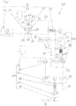
- Fig. 1 shows schematically in its entirety a device 100 for the production of foamed plastic parts, in particular sealing beads.
- This device 100 in turn has several essential subunits.
- Such a subunit is formed by a device 16 for producing a mixture of at least one gas and at least one liquid plastic component.
- This device 16 in turn has at least one mixing device 17, an introduction device 19 for the at least one gas connected to the mixing device 17 via a first line 18 and a delivery device 21 for the at least one liquid plastic component connected to the mixing device 17 via a second line 20.
- this device 16 has a container 53 for the plastic component and a gas source 54, in particular a compressed air generating device. Instead of the container 53, a feed pump could also be provided.
- such a device 16 provides that the introduction device 19 and the delivery device 21 are designed as piston pumps 25 and 24 having pistons 22 and 23.
- the piston 22 of the introduction device 19 (piston pump 25) and the piston 23 of the conveying device 21 (piston pump 24) are mechanically oppositely coupled in this example via a pressure booster 26.
- This allows the use of a drive that works at relatively low pressure (e.g. pneumatics) because the necessary increase in force takes place via the force transmission.
- Inlet valves 27, 28 and outlet valves 29, 30 can also be seen.
- these intake valves 27, 28 and exhaust valves 29, 30 are actuated by a control device 33 to match the movement of the coupled pistons 22, 23.
- a sensor 31 which is connected to the control device 33 for signal transmission via a signal line 32.
- the sensor 31 is used to determine the position of the pressure intensifier 26.
- the position of the pistons 22, 23 is also determined in this way.
- the position of the pistons 22, 23 can also be determined directly via the sensor 31 (see the further exemplary embodiments).
- Leakage detection can generally be carried out with such a sensor 31, namely when the piston seals between the piston 23 and the cylinder 34 of the insertion device 19, the piston seals between the piston 22 and the cylinder 35 of the delivery device 21 and / or at least one of the valves 27 to 30 are worn.
- inlet valve 28 and outlet valve 30 on the gas side are closed.
- the piston 22 compresses the gas volume located between inlet valve 28 and outlet valve 30. If there is a leak, there is an irregular movement of the pressure booster 26 after compression, which is detected by the sensor 31.
- Fig. 3 shows a single piston pump, which simultaneously forms the piston pump 24 for the delivery device 21 and the piston pump 25 for the introduction device 19.
- no separate pressure intensifier is provided; rather, a piston forms both the piston 23 of the piston pump 24 and the piston 22 of the piston pump 25 Fig. 3 works mechanically opposite. That is, if gas is discharged via the introduction device 19 (shown below), liquid plastic component is introduced into the conveying device 21 and vice versa.
- FIG. 4 a system in which the piston pumps 24 and 25 are mechanically synchronously coupled.
- the piston 22 of the introducing device 19 and the piston 23 of the conveying device 21 are coupled via a coupling mechanism 63 in such a way that when gas is discharged from the introducing device 19, liquid plastic component is discharged from the conveying device 21 and when gas is introduced into the introducing device 19 liquid plastic component is introduced into the conveyor 21.
- Fig. 5 shows an electronic coupling of the piston pumps 24 and 25.
- the movement of the pistons 22 and 23 is controlled by a control device 64, which is in signaling connection with drive devices of the two piston pumps 24 and 25.
- the pistons 22 and 23 can be moved in opposite directions or synchronously. This can be set via the control device 64.
- Fig. 6 shows a piston pump 25 and a piston pump 24, which alternately form the introduction device 19 or the delivery device 21.
- One advantage is that the seals are alternately lubricated by the liquid plastic component on both sides.
- the change takes place via switching devices 65 and 66, which can either be switched over manually or, preferably, switched over via a control device 67, preferably regularly.
- the liquid plastic component is conveyed from the container 53 via a first line 68 to the piston pump 24 (shown above), while the gas is conveyed from the gas source 54 via the second line 69 to the piston pump 25.
- the entire system agrees with the in this first switch position Fig. 1 and 2nd match.
- the liquid plastic component is conveyed from the container 53 via a third line 70 to the piston pump 25 (shown below), while the gas is conveyed from the gas source 54 to the piston pump 24 via a fourth line 71.
- the piston pump 25 thus forms the delivery device 21 and the piston pump 24 forms the introduction device 19, vice versa to the first switching position.
- the liquid plastic component or the gas is then supplied via the first line 18 or the second line 20 Mixing device 17 pumped on.
- a further subunit of the device 100 is formed by a device 36 for providing a liquid plastic component mixed with gas for a metering device 38.
- This device 36 has a source 37 for at least one liquid plastic component mixed with gas; this source 37 is formed by a line which leads away from the mixing device 17 already mentioned.
- this device 36 has an intermittently operating forwarding device for the at least one liquid plastic component mixed with gas. This intermittently operating forwarding device is formed by the piston pumps 24, 25. Intermittently working source will not only understood a source whose output drops to zero but also a source whose output is subject to strong fluctuations.
- the device 36 also has a metering device 38, preferably a metering pump, for which the plastic component is provided by the forwarding device.
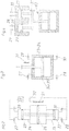
- the device 36 has a buffer device 39 with a variable buffer volume 40 arranged between the source 37 for the at least one liquid plastic component mixed with gas and the metering device 38, through which the liquid plastic component mixed with gas conveyed intermittently to the buffer device 39 is always in sufficient quantity is provided with sufficient preload pressure for the metering device 38.
- the liquid plastic component mixed with gas arrives at a metering valve 60, after which the liquid plastic component mixed with gas passes directly (see nozzle 61 shown in broken lines) - or as in FIG Fig. 1 shown indirectly via a further mixing element 58 - applied via a nozzle 61 and foamed by the application and the associated drop in pressure.
- the pressure prevailing between the buffer device 39 and the metering device 38 in the liquid plastic component mixed with gas can be controlled by the buffer device 39.
- the liquid plastic component mixed with gas reaches the buffer volume 40 of the buffer device 39 via an inlet opening 41.
- the buffer volume 40 is in turn connected to the metering device 38 via an outlet opening 42.
- the inlet opening 41 is formed in a wall of a housing 43 of the buffer device 39. This is also in Fig. 7 evident.
- the inlet opening 41 is formed in a piston rod 44 of the buffer device 39 connected to a piston 45 (see Fig. 8 ).
- an inlet valve 51 is arranged in front of the inlet opening and an outlet valve 52 is arranged behind the outlet opening 42.
- a displacement sensor 72 can be provided, with which at least selected positions of the piston 45 in the housing 43 can be determined.
- a pressure sensor 46 is arranged on an output side of the metering device 38.
- This pressure sensor 46 stands with one Control device 47 in connection via a control line 48.
- the control device 47 controls the buffer device 39 in such a way that the pressure present on the input side of the metering device 38 tracks the pressure prevailing on the output side of the metering device 38.
- the control device 47 can be designed to close both the inlet valve 51 and the outlet valve 52 and to compress the liquid plastic component mixed with gas located in the buffer volume 40.
- a sensor (not shown) can be provided, by means of which an irregular compression of the buffer volume 40 can be detected.
- the buffer device 39 is connected to a device 49 for pressurizing the buffer device 39. This can be controlled either by the control device 47 (line shown in broken lines) or by an independent control device 50.
- the two devices 16 and 36 would already suffice for the production of foamed plastic parts in the form of sealing beads.
- a second plastic component foams in parallel to the first plastic component or mixed with the first plastic component to form the plastic part, preferably physically. Therefore, a further subunit of the device 100 is formed by a device 62 for multi-component foaming (see again Fig. 1 ).
- This device 54 has a container 55 for a second plastic component, from which the second plastic component, preferably mixed with gas, is guided to the mixing element 58 via a metering device 56 and a metering valve 57. In this mixing element 58, this second plastic component is mixed with the first plastic component.
- This mixture is then discharged after a further metering valve 59 through a schematically indicated nozzle 61, whereby the gas contained in the mixture foams.
- the application results in a drop in pressure
- the gas causes the liquid plastic component to foam and, after the foamed plastic component has cured, a plastic part provided with pores is formed, for example in the form of a sealing bead 73.
- Check valves can also be provided in the metering valves 57 and / or 60, as in the Fig. 1 provided with the reference numerals 51 and 52 can be used as inlet and outlet valve.
Landscapes
- Engineering & Computer Science (AREA)
- Mechanical Engineering (AREA)
- General Engineering & Computer Science (AREA)
- Robotics (AREA)
- Processing And Handling Of Plastics And Other Materials For Molding In General (AREA)
- Casting Or Compression Moulding Of Plastics Or The Like (AREA)
- Molding Of Porous Articles (AREA)
Claims (11)
- Dispositif (100) de fabrication de pièces en plastique moussées, en particulier de cordons de joints d'étanchéité, comprenant- un récipient (53) ou une pompe d'alimentation pour un composant plastique liquide,- une source de gaz (54),- au moins un dispositif de mélange (17),- un dispositif d'introduction (19) pour l'au moins un gaz, relié au dispositif de mélange (17) par une première conduite (18), dans lequel le dispositif d'introduction (19) est réalisé sous la forme d'une première pompe à piston (25) comportant un piston (22),- un dispositif de transport (21) pour l'au moins un composant plastique liquide, relié au dispositif de mélange (17) par une seconde conduite (20), dans lequel le dispositif de transport (21) est réalisé sous la forme d'une seconde pompe à piston (24) comportant un piston (23),- un dispositif de transfert fonctionnant de manière intermittente, lequel est formé par les pompes à piston (24, 25),- une source (37) pour l'au moins un composant plastique liquide mélangé à du gaz, ladite source (37) étant formée par une conduite s'éloignant du dispositif de mélange (17), et- un dispositif de dosage (38),
dans lequel l'au moins un composant plastique liquide mélangé à du gaz peut être fourni au dispositif de dosage (38), de manière intermittente, par le dispositif de transfert fonctionnant de manière intermittente par l'intermédiaire de la source (37), caractérisé en ce qu'un dispositif tampon (39) présentant un volume tampon (40) variable, relié à la source (37) par l'intermédiaire d'une ouverture d'entrée (41) et au dispositif de dosage (38) par l'intermédiaire d'une ouverture de sortie (42), est disposé entre la source (37) pour l'au moins un composant plastique liquide mélangé à du gaz et le dispositif de dosage (38). - Dispositif (100) selon la revendication 1, caractérisé en ce que la pression régnant entre le dispositif tampon (39) et le dispositif de dosage (38) dans le composant plastique liquide peut être réglée (de préférence à une valeur constante) par le dispositif tampon (39).
- Dispositif (100) selon au moins l'une des revendications précédentes, caractérisé en ce qu'un capteur de pression (46) est disposé sur un côté de sortie du dispositif de dosage (38), lequel capteur de pression est relié à un dispositif de commande (47), dans lequel le dispositif de commande (47) commande le dispositif tampon (39) par l'intermédiaire d'une conduite de commande (48) de telle manière que la pression appliquée sur un côté d'entrée du dispositif de dosage (38) est adaptée à la pression régnant sur le côté de sortie du dispositif de dosage (38).
- Dispositif (100) selon au moins l'une des revendications précédentes, caractérisé en ce que la source (37) amène ou fournit un composant plastique liquide mélangé à du gaz au dispositif tampon (39).
- Dispositif (100) selon au moins l'une des revendications précédentes, caractérisé en ce que l'ouverture d'entrée (41) ou l'ouverture de sortie (42) est réalisée dans une paroi d'un boîtier (43) du dispositif tampon (39).
- Dispositif (100) selon au moins l'une des revendications précédentes, caractérisé en ce que l'ouverture d'entrée (41) ou l'ouverture de sortie (42) est réalisée dans une tige de piston (44) du dispositif tampon (39) reliée à un piston (45).
- Dispositif (100) selon au moins l'une des revendications précédentes, caractérisé en ce que le dispositif tampon (39) est relié à un dispositif (49) pouvant être commandé par un dispositif de commande (47, 50) de façon à pressuriser le dispositif tampon (39), lequel dispositif présente de préférence une conception de type pneumatique.
- Dispositif (100) selon au moins l'une des revendications précédentes, caractérisé en ce que le dispositif (36) est conçu pour la fabrication d'une pièce en plastique physiquement moussée.
- Dispositif (100) selon au moins l'une des revendications précédentes, caractérisé en ce que le dispositif tampon (39) comporte un piston (45) pouvant se déplacer dans un boîtier (43), dans lequel, de préférence, un capteur de déplacement est prévu pour déterminer au moins des positions sélectionnées du piston (45) dans le boîtier (43).
- Dispositif (100) selon au moins l'une des revendications précédentes, caractérisé en ce qu'une soupape d'entrée (51) est disposée devant l'ouverture d'entrée (41) et en ce qu'une soupape de sortie (52) est disposée derrière l'ouverture de sortie (42), lesquelles soupapes peuvent être commandées par un dispositif de commande.
- Dispositif (100) selon la revendication 10, caractérisé en ce que le dispositif de commande est conçu pour fermer aussi bien la soupape d'entrée (51) que la soupape de sortie (52) et pour comprimer le composant plastique liquide se trouvant dans le volume tampon (40), et en ce qu'un capteur est prévu, lequel capteur permet de détecter une réduction ou une compression irrégulière du volume tampon (40).
Applications Claiming Priority (2)
| Application Number | Priority Date | Filing Date | Title |
|---|---|---|---|
| ATA432/2015A AT517359B1 (de) | 2015-07-03 | 2015-07-03 | Vorrichtung mit intermittierend bereitgestellter flüssiger Kunststoffkomponente |
| PCT/AT2016/050226 WO2017004635A1 (fr) | 2015-07-03 | 2016-06-24 | Dispositif à alimentation intermittente en composant plastique liquide |
Publications (2)
| Publication Number | Publication Date |
|---|---|
| EP3317063A1 EP3317063A1 (fr) | 2018-05-09 |
| EP3317063B1 true EP3317063B1 (fr) | 2020-06-03 |
Family
ID=56463969
Family Applications (1)
| Application Number | Title | Priority Date | Filing Date |
|---|---|---|---|
| EP16740938.2A Active EP3317063B1 (fr) | 2015-07-03 | 2016-06-24 | Dispositif à alimentation intermittente d'un composant polymérique liquide mélangé à un gaz |
Country Status (10)
| Country | Link |
|---|---|
| US (1) | US10960575B2 (fr) |
| EP (1) | EP3317063B1 (fr) |
| JP (1) | JP6689295B2 (fr) |
| KR (1) | KR102050176B1 (fr) |
| CN (1) | CN107848144B (fr) |
| AT (1) | AT517359B1 (fr) |
| AU (1) | AU2016291289B2 (fr) |
| RU (1) | RU2693150C1 (fr) |
| SG (1) | SG11201800048QA (fr) |
| WO (1) | WO2017004635A1 (fr) |
Families Citing this family (4)
| Publication number | Priority date | Publication date | Assignee | Title |
|---|---|---|---|---|
| EP3450024B1 (fr) * | 2017-08-30 | 2023-02-01 | Wagner International Ag | Installation de dosage et d'application pour un matériau polymère durci sous l'effet de l'humidité |
| AT519978B1 (de) | 2017-12-19 | 2018-12-15 | Sonderhoff Eng Gmbh | Vorrichtung zur Herstellung von Kunststoffteilen |
| EP4239194A1 (fr) | 2022-03-02 | 2023-09-06 | Henkel AG & Co. KGaA | Procédé de régulation de la pression de refoulement d'une pompe d'alimentation |
| DE102022118228A1 (de) | 2022-07-21 | 2024-02-01 | Atlas Copco Ias Gmbh | Vorrichtung zum Fördern von viskosem Material |
Citations (3)
| Publication number | Priority date | Publication date | Assignee | Title |
|---|---|---|---|---|
| SU1260220A1 (ru) * | 1985-01-02 | 1986-09-30 | Специальное конструкторско-технологическое бюро с опытным производством при Белорусском государственном университете им.В.И.Ленина | Смесительно-дозирующа установка |
| US5551486A (en) * | 1993-03-14 | 1996-09-03 | Wilhelm Hedrich Vakuumanlagen Gmbh & Co. Kg | Method and equipment for filing casting molds with casting resin or similarly casting-ready liquid media |
| RU2142358C1 (ru) * | 1998-11-24 | 1999-12-10 | Открытое акционерное общество "ГАЗ" | Установка для дозирования и смешивания жидкостей |
Family Cites Families (23)
| Publication number | Priority date | Publication date | Assignee | Title |
|---|---|---|---|---|
| GB904003A (en) * | 1958-02-06 | 1962-08-22 | Dunlop Rubber Co | Method and apparatus for the production of cellular synthetic rubber |
| US3627275A (en) | 1967-01-09 | 1971-12-14 | Frederick E Gusmer | Apparatus for producing plastic foam |
| DE2027190A1 (de) | 1970-06-03 | 1971-12-09 | Gebert V | Rohrmischverfahren mit Einlegeschlauch zur Plastikschaumherstellung mit intermittierenden Dosiervornchtungen und Kernzahlregelung |
| US3908862A (en) | 1974-08-29 | 1975-09-30 | Cincinnati Milacron Inc | Ratio controlled mixing of liquids |
| GB1503648A (en) | 1975-04-23 | 1978-03-15 | Jennings G | Pumping apparatus |
| US4171191A (en) | 1976-03-25 | 1979-10-16 | Krueger Wallace F | Apparatus for transferring metered quantities of material from one location to another |
| GB1532045A (en) | 1976-09-28 | 1978-11-15 | Liquid Controls Ltd | Pump drive system |
| DE2748982C2 (de) * | 1977-11-02 | 1987-10-01 | Wilhelm Hedrich Vakuumanlagen GmbH und Co KG, 6332 Ehringshausen | Anordnung zum Füllen von Gießformen mit Gießharz od.dgl. gießfähig flüssigen Medien |
| US4275172A (en) | 1980-01-28 | 1981-06-23 | Union Carbide Corporation | Frothable polyurethane composition and a cellular foam produced therefrom suitable for use in joints between wallboards |
| SU987395A1 (ru) * | 1980-11-27 | 1983-01-07 | Институт Ботаники Ан Казсср | Устройство дл микродозировани жидкостей |
| FR2595121B1 (fr) * | 1986-03-03 | 1988-07-01 | Beraud Jean Louis | Pompe doseuse destinee a debiter deux composants en proportion determinee |
| DE3913000A1 (de) * | 1988-04-20 | 1989-12-07 | Lenhardt Maschinenbau | Vorrichtung zum abgeben hochviskoser, pastoeser, kompressibler substanzen |
| WO1989010206A1 (fr) * | 1988-04-20 | 1989-11-02 | Lenhardt Maschinenbau Gmbh | Dispositif distributeur de substances compressibles pateuses a viscosite elevee |
| JP2709425B2 (ja) * | 1992-02-07 | 1998-02-04 | 東海化成工業株式会社 | 発泡ウレタン樹脂混合装置 |
| JP3177037B2 (ja) * | 1992-12-28 | 2001-06-18 | タイヨーテクノ株式会社 | 流動性材料にガスを混入させる方法 |
| WO1996026057A1 (fr) * | 1995-02-20 | 1996-08-29 | Wilhelm Hedrich Vakuumanlagen Gmbh & Co. Kg | Dispositif pour distribuer des materiaux coulants composes d'au moins deux constituants mutuellement reactifs, notamment des resines de coulees |
| US6538040B1 (en) | 1995-12-01 | 2003-03-25 | Sunstar Giken Kabushiki Kaisha | Method and apparatus for mixing a high-viscosity material into a gas |
| US6234355B1 (en) * | 1997-08-07 | 2001-05-22 | Lenhardt Maschinenbau Gmbh | Machine for filling the edge joints of insulating glass panes with a sealing compound consisting of two constituents |
| JP2001200877A (ja) * | 2000-01-14 | 2001-07-27 | Tokai Rubber Ind Ltd | バウンドストッパの製造方法 |
| KR101255770B1 (ko) | 2004-07-26 | 2013-04-17 | 우베 고산 기카이 가부시키가이샤 | 열가소성 수지의 사출발포 성형방법 |
| EP2067992A1 (fr) * | 2007-12-06 | 2009-06-10 | Groupe E SA | Compresseur et appareil pour comprimer deux gaz à haute pression |
| KR101338650B1 (ko) | 2012-02-21 | 2013-12-09 | 서호성 | 직교류형 냉각탑 |
| KR101388650B1 (ko) * | 2013-09-11 | 2014-04-24 | 주식회사 듀라테크 | 주형 우레탄용 사출방법 |
-
2015
- 2015-07-03 AT ATA432/2015A patent/AT517359B1/de not_active IP Right Cessation
-
2016
- 2016-06-24 SG SG11201800048QA patent/SG11201800048QA/en unknown
- 2016-06-24 US US15/740,220 patent/US10960575B2/en not_active Expired - Fee Related
- 2016-06-24 AU AU2016291289A patent/AU2016291289B2/en not_active Ceased
- 2016-06-24 EP EP16740938.2A patent/EP3317063B1/fr active Active
- 2016-06-24 WO PCT/AT2016/050226 patent/WO2017004635A1/fr not_active Ceased
- 2016-06-24 JP JP2017565994A patent/JP6689295B2/ja not_active Expired - Fee Related
- 2016-06-24 CN CN201680042445.3A patent/CN107848144B/zh not_active Expired - Fee Related
- 2016-06-24 KR KR1020187003032A patent/KR102050176B1/ko not_active Expired - Fee Related
- 2016-06-24 RU RU2018103379A patent/RU2693150C1/ru active
Patent Citations (3)
| Publication number | Priority date | Publication date | Assignee | Title |
|---|---|---|---|---|
| SU1260220A1 (ru) * | 1985-01-02 | 1986-09-30 | Специальное конструкторско-технологическое бюро с опытным производством при Белорусском государственном университете им.В.И.Ленина | Смесительно-дозирующа установка |
| US5551486A (en) * | 1993-03-14 | 1996-09-03 | Wilhelm Hedrich Vakuumanlagen Gmbh & Co. Kg | Method and equipment for filing casting molds with casting resin or similarly casting-ready liquid media |
| RU2142358C1 (ru) * | 1998-11-24 | 1999-12-10 | Открытое акционерное общество "ГАЗ" | Установка для дозирования и смешивания жидкостей |
Also Published As
| Publication number | Publication date |
|---|---|
| KR102050176B1 (ko) | 2019-11-28 |
| US10960575B2 (en) | 2021-03-30 |
| AT517359B1 (de) | 2017-01-15 |
| EP3317063A1 (fr) | 2018-05-09 |
| AU2016291289A1 (en) | 2018-01-18 |
| AT517359A4 (de) | 2017-01-15 |
| SG11201800048QA (en) | 2018-02-27 |
| CN107848144B (zh) | 2020-07-07 |
| JP6689295B2 (ja) | 2020-04-28 |
| US20180186033A1 (en) | 2018-07-05 |
| KR20180022959A (ko) | 2018-03-06 |
| AU2016291289B2 (en) | 2019-05-30 |
| RU2693150C1 (ru) | 2019-07-01 |
| CN107848144A (zh) | 2018-03-27 |
| JP2018526243A (ja) | 2018-09-13 |
| WO2017004635A1 (fr) | 2017-01-12 |
Similar Documents
| Publication | Publication Date | Title |
|---|---|---|
| EP3317538B1 (fr) | Dispositif pour produire un mélange composé d'au moins un gaz et d'au moins un composant plastique liquide | |
| DE2612609C3 (de) | Pumpensystem | |
| EP3317063B1 (fr) | Dispositif à alimentation intermittente d'un composant polymérique liquide mélangé à un gaz | |
| EP2202496B1 (fr) | Doseur à piston doté d'une soupape contrôlée | |
| EP4132722B1 (fr) | Pompe à agent de revêtement, installation de revêtement et procédé de fonctionnement associé | |
| EP3450024B1 (fr) | Installation de dosage et d'application pour un matériau polymère durci sous l'effet de l'humidité | |
| EP2760584A1 (fr) | Procédé et dispositif pour doser un fluide de travail | |
| EP0810917B1 (fr) | Dispositif pour distribuer des materiaux coulants composes d'au moins deux constituants mutuellement reactifs, notamment des resines de coulees | |
| DE202014002818U1 (de) | Beschichtungssystem zum Beschichten von Gegenständen | |
| EP2895744B1 (fr) | Pompe syringe pour un dosage sans pulsations et un mélange précis dans le domaine hplc, uhplc, micro- et nano-hplc | |
| WO2019243131A1 (fr) | Système de nettoyage hydraulique à régulation électronique | |
| DE102007048520A1 (de) | Sprühbeschichtungspulver-Fördervorrichtung und Pulversprühbeschichtungsvorrichtung | |
| EP1967281B1 (fr) | Tube de pompage et dispositif de pompage | |
| DE102012209787B4 (de) | Pumpensystem mit Förderschnecke sowie Pumpverfahren | |
| DE10320550B4 (de) | Lackdosiereinrichtung | |
| DE3504107A1 (de) | Hydraulisches dosier- und foerdersystem | |
| DE3927332C2 (de) | Vorrichtung zum pneumatischen Ausbringen von hydromechanisch im Dichtstrom gefördertem Beton | |
| EP3861416A1 (fr) | Système d'éjection de liquide pour une installation de lavage de véhicules et son procédé de fonctionnement | |
| DE102019109083A1 (de) | Verfahren zur Steuerung einer Dickstoffpumpe und Dickstoffpumpe | |
| EP3936235A1 (fr) | Installation de revêtement destinée au revêtement de pièces d'une matière de revêtement | |
| DE3420818A1 (de) | Verfahren zur dosierung von elutionsmitteln in der hplc durch flow-feedback mittels eines dosierventils und eines elutionsmittelunabhaengigen flussmesssystems | |
| DE102014105044A1 (de) | System zum Fördern von Beschichtungspulver und Verfahren zum Betreiben eines solchen Systems | |
| DE3535175A1 (de) | Verfahren zur steuerung hydrostatisch angetriebener duplex-plunger-pumpen und hydrostatisch angetriebene duplex-plunger-pumpe | |
| DE3607115A1 (de) | Pneumatische pumpensteuerung fuer zumindest eine foerderpumpe | |
| DE102018132270A1 (de) | Kolbenpumpe und Verfahren zum Betrieb einer Kolbenpumpe |
Legal Events
| Date | Code | Title | Description |
|---|---|---|---|
| STAA | Information on the status of an ep patent application or granted ep patent |
Free format text: STATUS: THE INTERNATIONAL PUBLICATION HAS BEEN MADE |
|
| PUAI | Public reference made under article 153(3) epc to a published international application that has entered the european phase |
Free format text: ORIGINAL CODE: 0009012 |
|
| STAA | Information on the status of an ep patent application or granted ep patent |
Free format text: STATUS: REQUEST FOR EXAMINATION WAS MADE |
|
| 17P | Request for examination filed |
Effective date: 20180125 |
|
| AK | Designated contracting states |
Kind code of ref document: A1 Designated state(s): AL AT BE BG CH CY CZ DE DK EE ES FI FR GB GR HR HU IE IS IT LI LT LU LV MC MK MT NL NO PL PT RO RS SE SI SK SM TR |
|
| AX | Request for extension of the european patent |
Extension state: BA ME |
|
| DAV | Request for validation of the european patent (deleted) | ||
| DAX | Request for extension of the european patent (deleted) | ||
| STAA | Information on the status of an ep patent application or granted ep patent |
Free format text: STATUS: EXAMINATION IS IN PROGRESS |
|
| 17Q | First examination report despatched |
Effective date: 20190104 |
|
| GRAP | Despatch of communication of intention to grant a patent |
Free format text: ORIGINAL CODE: EPIDOSNIGR1 |
|
| STAA | Information on the status of an ep patent application or granted ep patent |
Free format text: STATUS: GRANT OF PATENT IS INTENDED |
|
| RIC1 | Information provided on ipc code assigned before grant |
Ipc: B29B 7/74 20060101AFI20191209BHEP Ipc: F04B 13/00 20060101ALI20191209BHEP Ipc: F04B 9/123 20060101ALI20191209BHEP |
|
| INTG | Intention to grant announced |
Effective date: 20200102 |
|
| GRAS | Grant fee paid |
Free format text: ORIGINAL CODE: EPIDOSNIGR3 |
|
| GRAA | (expected) grant |
Free format text: ORIGINAL CODE: 0009210 |
|
| STAA | Information on the status of an ep patent application or granted ep patent |
Free format text: STATUS: THE PATENT HAS BEEN GRANTED |
|
| RAP1 | Party data changed (applicant data changed or rights of an application transferred) |
Owner name: HENKEL AG & CO. KGAA |
|
| AK | Designated contracting states |
Kind code of ref document: B1 Designated state(s): AL AT BE BG CH CY CZ DE DK EE ES FI FR GB GR HR HU IE IS IT LI LT LU LV MC MK MT NL NO PL PT RO RS SE SI SK SM TR |
|
| REG | Reference to a national code |
Ref country code: GB Ref legal event code: FG4D Free format text: NOT ENGLISH |
|
| REG | Reference to a national code |
Ref country code: CH Ref legal event code: EP Ref country code: AT Ref legal event code: REF Ref document number: 1276559 Country of ref document: AT Kind code of ref document: T Effective date: 20200615 |
|
| REG | Reference to a national code |
Ref country code: DE Ref legal event code: R096 Ref document number: 502016010124 Country of ref document: DE |
|
| REG | Reference to a national code |
Ref country code: LT Ref legal event code: MG4D |
|
| PG25 | Lapsed in a contracting state [announced via postgrant information from national office to epo] |
Ref country code: SE Free format text: LAPSE BECAUSE OF FAILURE TO SUBMIT A TRANSLATION OF THE DESCRIPTION OR TO PAY THE FEE WITHIN THE PRESCRIBED TIME-LIMIT Effective date: 20200603 Ref country code: LT Free format text: LAPSE BECAUSE OF FAILURE TO SUBMIT A TRANSLATION OF THE DESCRIPTION OR TO PAY THE FEE WITHIN THE PRESCRIBED TIME-LIMIT Effective date: 20200603 Ref country code: NO Free format text: LAPSE BECAUSE OF FAILURE TO SUBMIT A TRANSLATION OF THE DESCRIPTION OR TO PAY THE FEE WITHIN THE PRESCRIBED TIME-LIMIT Effective date: 20200903 Ref country code: GR Free format text: LAPSE BECAUSE OF FAILURE TO SUBMIT A TRANSLATION OF THE DESCRIPTION OR TO PAY THE FEE WITHIN THE PRESCRIBED TIME-LIMIT Effective date: 20200904 Ref country code: FI Free format text: LAPSE BECAUSE OF FAILURE TO SUBMIT A TRANSLATION OF THE DESCRIPTION OR TO PAY THE FEE WITHIN THE PRESCRIBED TIME-LIMIT Effective date: 20200603 |
|
| REG | Reference to a national code |
Ref country code: NL Ref legal event code: MP Effective date: 20200603 |
|
| PG25 | Lapsed in a contracting state [announced via postgrant information from national office to epo] |
Ref country code: LV Free format text: LAPSE BECAUSE OF FAILURE TO SUBMIT A TRANSLATION OF THE DESCRIPTION OR TO PAY THE FEE WITHIN THE PRESCRIBED TIME-LIMIT Effective date: 20200603 Ref country code: RS Free format text: LAPSE BECAUSE OF FAILURE TO SUBMIT A TRANSLATION OF THE DESCRIPTION OR TO PAY THE FEE WITHIN THE PRESCRIBED TIME-LIMIT Effective date: 20200603 Ref country code: HR Free format text: LAPSE BECAUSE OF FAILURE TO SUBMIT A TRANSLATION OF THE DESCRIPTION OR TO PAY THE FEE WITHIN THE PRESCRIBED TIME-LIMIT Effective date: 20200603 Ref country code: BG Free format text: LAPSE BECAUSE OF FAILURE TO SUBMIT A TRANSLATION OF THE DESCRIPTION OR TO PAY THE FEE WITHIN THE PRESCRIBED TIME-LIMIT Effective date: 20200903 |
|
| PG25 | Lapsed in a contracting state [announced via postgrant information from national office to epo] |
Ref country code: NL Free format text: LAPSE BECAUSE OF FAILURE TO SUBMIT A TRANSLATION OF THE DESCRIPTION OR TO PAY THE FEE WITHIN THE PRESCRIBED TIME-LIMIT Effective date: 20200603 Ref country code: AL Free format text: LAPSE BECAUSE OF FAILURE TO SUBMIT A TRANSLATION OF THE DESCRIPTION OR TO PAY THE FEE WITHIN THE PRESCRIBED TIME-LIMIT Effective date: 20200603 |
|
| PG25 | Lapsed in a contracting state [announced via postgrant information from national office to epo] |
Ref country code: RO Free format text: LAPSE BECAUSE OF FAILURE TO SUBMIT A TRANSLATION OF THE DESCRIPTION OR TO PAY THE FEE WITHIN THE PRESCRIBED TIME-LIMIT Effective date: 20200603 Ref country code: IT Free format text: LAPSE BECAUSE OF FAILURE TO SUBMIT A TRANSLATION OF THE DESCRIPTION OR TO PAY THE FEE WITHIN THE PRESCRIBED TIME-LIMIT Effective date: 20200603 Ref country code: PT Free format text: LAPSE BECAUSE OF FAILURE TO SUBMIT A TRANSLATION OF THE DESCRIPTION OR TO PAY THE FEE WITHIN THE PRESCRIBED TIME-LIMIT Effective date: 20201006 Ref country code: CZ Free format text: LAPSE BECAUSE OF FAILURE TO SUBMIT A TRANSLATION OF THE DESCRIPTION OR TO PAY THE FEE WITHIN THE PRESCRIBED TIME-LIMIT Effective date: 20200603 Ref country code: ES Free format text: LAPSE BECAUSE OF FAILURE TO SUBMIT A TRANSLATION OF THE DESCRIPTION OR TO PAY THE FEE WITHIN THE PRESCRIBED TIME-LIMIT Effective date: 20200603 Ref country code: SM Free format text: LAPSE BECAUSE OF FAILURE TO SUBMIT A TRANSLATION OF THE DESCRIPTION OR TO PAY THE FEE WITHIN THE PRESCRIBED TIME-LIMIT Effective date: 20200603 Ref country code: EE Free format text: LAPSE BECAUSE OF FAILURE TO SUBMIT A TRANSLATION OF THE DESCRIPTION OR TO PAY THE FEE WITHIN THE PRESCRIBED TIME-LIMIT Effective date: 20200603 |
|
| REG | Reference to a national code |
Ref country code: CH Ref legal event code: PL |
|
| PG25 | Lapsed in a contracting state [announced via postgrant information from national office to epo] |
Ref country code: SK Free format text: LAPSE BECAUSE OF FAILURE TO SUBMIT A TRANSLATION OF THE DESCRIPTION OR TO PAY THE FEE WITHIN THE PRESCRIBED TIME-LIMIT Effective date: 20200603 Ref country code: PL Free format text: LAPSE BECAUSE OF FAILURE TO SUBMIT A TRANSLATION OF THE DESCRIPTION OR TO PAY THE FEE WITHIN THE PRESCRIBED TIME-LIMIT Effective date: 20200603 Ref country code: IS Free format text: LAPSE BECAUSE OF FAILURE TO SUBMIT A TRANSLATION OF THE DESCRIPTION OR TO PAY THE FEE WITHIN THE PRESCRIBED TIME-LIMIT Effective date: 20201003 |
|
| REG | Reference to a national code |
Ref country code: DE Ref legal event code: R097 Ref document number: 502016010124 Country of ref document: DE |
|
| PG25 | Lapsed in a contracting state [announced via postgrant information from national office to epo] |
Ref country code: MC Free format text: LAPSE BECAUSE OF FAILURE TO SUBMIT A TRANSLATION OF THE DESCRIPTION OR TO PAY THE FEE WITHIN THE PRESCRIBED TIME-LIMIT Effective date: 20200603 Ref country code: LU Free format text: LAPSE BECAUSE OF NON-PAYMENT OF DUE FEES Effective date: 20200624 |
|
| PLBE | No opposition filed within time limit |
Free format text: ORIGINAL CODE: 0009261 |
|
| STAA | Information on the status of an ep patent application or granted ep patent |
Free format text: STATUS: NO OPPOSITION FILED WITHIN TIME LIMIT |
|
| REG | Reference to a national code |
Ref country code: BE Ref legal event code: MM Effective date: 20200630 |
|
| PG25 | Lapsed in a contracting state [announced via postgrant information from national office to epo] |
Ref country code: LI Free format text: LAPSE BECAUSE OF NON-PAYMENT OF DUE FEES Effective date: 20200630 Ref country code: CH Free format text: LAPSE BECAUSE OF NON-PAYMENT OF DUE FEES Effective date: 20200630 Ref country code: DK Free format text: LAPSE BECAUSE OF FAILURE TO SUBMIT A TRANSLATION OF THE DESCRIPTION OR TO PAY THE FEE WITHIN THE PRESCRIBED TIME-LIMIT Effective date: 20200603 Ref country code: IE Free format text: LAPSE BECAUSE OF NON-PAYMENT OF DUE FEES Effective date: 20200624 |
|
| 26N | No opposition filed |
Effective date: 20210304 |
|
| GBPC | Gb: european patent ceased through non-payment of renewal fee |
Effective date: 20200903 |
|
| PG25 | Lapsed in a contracting state [announced via postgrant information from national office to epo] |
Ref country code: BE Free format text: LAPSE BECAUSE OF NON-PAYMENT OF DUE FEES Effective date: 20200630 Ref country code: SI Free format text: LAPSE BECAUSE OF FAILURE TO SUBMIT A TRANSLATION OF THE DESCRIPTION OR TO PAY THE FEE WITHIN THE PRESCRIBED TIME-LIMIT Effective date: 20200603 |
|
| PG25 | Lapsed in a contracting state [announced via postgrant information from national office to epo] |
Ref country code: GB Free format text: LAPSE BECAUSE OF NON-PAYMENT OF DUE FEES Effective date: 20200903 |
|
| PG25 | Lapsed in a contracting state [announced via postgrant information from national office to epo] |
Ref country code: TR Free format text: LAPSE BECAUSE OF FAILURE TO SUBMIT A TRANSLATION OF THE DESCRIPTION OR TO PAY THE FEE WITHIN THE PRESCRIBED TIME-LIMIT Effective date: 20200603 Ref country code: MT Free format text: LAPSE BECAUSE OF FAILURE TO SUBMIT A TRANSLATION OF THE DESCRIPTION OR TO PAY THE FEE WITHIN THE PRESCRIBED TIME-LIMIT Effective date: 20200603 Ref country code: CY Free format text: LAPSE BECAUSE OF FAILURE TO SUBMIT A TRANSLATION OF THE DESCRIPTION OR TO PAY THE FEE WITHIN THE PRESCRIBED TIME-LIMIT Effective date: 20200603 |
|
| PG25 | Lapsed in a contracting state [announced via postgrant information from national office to epo] |
Ref country code: MK Free format text: LAPSE BECAUSE OF FAILURE TO SUBMIT A TRANSLATION OF THE DESCRIPTION OR TO PAY THE FEE WITHIN THE PRESCRIBED TIME-LIMIT Effective date: 20200603 |
|
| REG | Reference to a national code |
Ref country code: AT Ref legal event code: MM01 Ref document number: 1276559 Country of ref document: AT Kind code of ref document: T Effective date: 20210624 |
|
| PG25 | Lapsed in a contracting state [announced via postgrant information from national office to epo] |
Ref country code: AT Free format text: LAPSE BECAUSE OF NON-PAYMENT OF DUE FEES Effective date: 20210624 |
|
| P01 | Opt-out of the competence of the unified patent court (upc) registered |
Effective date: 20230530 |
|
| PGFP | Annual fee paid to national office [announced via postgrant information from national office to epo] |
Ref country code: DE Payment date: 20250618 Year of fee payment: 10 |
|
| PGFP | Annual fee paid to national office [announced via postgrant information from national office to epo] |
Ref country code: FR Payment date: 20250625 Year of fee payment: 10 |