EP3317580B1 - Module d'éclairage pour un phare de véhicule - Google Patents
Module d'éclairage pour un phare de véhicule Download PDFInfo
- Publication number
- EP3317580B1 EP3317580B1 EP16732218.9A EP16732218A EP3317580B1 EP 3317580 B1 EP3317580 B1 EP 3317580B1 EP 16732218 A EP16732218 A EP 16732218A EP 3317580 B1 EP3317580 B1 EP 3317580B1
- Authority
- EP
- European Patent Office
- Prior art keywords
- light
- face
- vehicle headlamp
- light exit
- carrier element
- Prior art date
- Legal status (The legal status is an assumption and is not a legal conclusion. Google has not performed a legal analysis and makes no representation as to the accuracy of the status listed.)
- Active
Links
Images


Classifications
-
- F—MECHANICAL ENGINEERING; LIGHTING; HEATING; WEAPONS; BLASTING
- F21—LIGHTING
- F21S—NON-PORTABLE LIGHTING DEVICES; SYSTEMS THEREOF; VEHICLE LIGHTING DEVICES SPECIALLY ADAPTED FOR VEHICLE EXTERIORS
- F21S41/00—Illuminating devices specially adapted for vehicle exteriors, e.g. headlamps
- F21S41/10—Illuminating devices specially adapted for vehicle exteriors, e.g. headlamps characterised by the light source
- F21S41/14—Illuminating devices specially adapted for vehicle exteriors, e.g. headlamps characterised by the light source characterised by the type of light source
-
- F—MECHANICAL ENGINEERING; LIGHTING; HEATING; WEAPONS; BLASTING
- F21—LIGHTING
- F21S—NON-PORTABLE LIGHTING DEVICES; SYSTEMS THEREOF; VEHICLE LIGHTING DEVICES SPECIALLY ADAPTED FOR VEHICLE EXTERIORS
- F21S41/00—Illuminating devices specially adapted for vehicle exteriors, e.g. headlamps
- F21S41/10—Illuminating devices specially adapted for vehicle exteriors, e.g. headlamps characterised by the light source
- F21S41/14—Illuminating devices specially adapted for vehicle exteriors, e.g. headlamps characterised by the light source characterised by the type of light source
- F21S41/16—Laser light sources
-
- F—MECHANICAL ENGINEERING; LIGHTING; HEATING; WEAPONS; BLASTING
- F21—LIGHTING
- F21S—NON-PORTABLE LIGHTING DEVICES; SYSTEMS THEREOF; VEHICLE LIGHTING DEVICES SPECIALLY ADAPTED FOR VEHICLE EXTERIORS
- F21S41/00—Illuminating devices specially adapted for vehicle exteriors, e.g. headlamps
- F21S41/10—Illuminating devices specially adapted for vehicle exteriors, e.g. headlamps characterised by the light source
- F21S41/14—Illuminating devices specially adapted for vehicle exteriors, e.g. headlamps characterised by the light source characterised by the type of light source
- F21S41/176—Light sources where the light is generated by photoluminescent material spaced from a primary light generating element
-
- F—MECHANICAL ENGINEERING; LIGHTING; HEATING; WEAPONS; BLASTING
- F21—LIGHTING
- F21S—NON-PORTABLE LIGHTING DEVICES; SYSTEMS THEREOF; VEHICLE LIGHTING DEVICES SPECIALLY ADAPTED FOR VEHICLE EXTERIORS
- F21S41/00—Illuminating devices specially adapted for vehicle exteriors, e.g. headlamps
- F21S41/20—Illuminating devices specially adapted for vehicle exteriors, e.g. headlamps characterised by refractors, transparent cover plates, light guides or filters
- F21S41/24—Light guides
-
- F—MECHANICAL ENGINEERING; LIGHTING; HEATING; WEAPONS; BLASTING
- F21—LIGHTING
- F21S—NON-PORTABLE LIGHTING DEVICES; SYSTEMS THEREOF; VEHICLE LIGHTING DEVICES SPECIALLY ADAPTED FOR VEHICLE EXTERIORS
- F21S41/00—Illuminating devices specially adapted for vehicle exteriors, e.g. headlamps
- F21S41/20—Illuminating devices specially adapted for vehicle exteriors, e.g. headlamps characterised by refractors, transparent cover plates, light guides or filters
- F21S41/25—Projection lenses
- F21S41/255—Lenses with a front view of circular or truncated circular outline
-
- F—MECHANICAL ENGINEERING; LIGHTING; HEATING; WEAPONS; BLASTING
- F21—LIGHTING
- F21S—NON-PORTABLE LIGHTING DEVICES; SYSTEMS THEREOF; VEHICLE LIGHTING DEVICES SPECIALLY ADAPTED FOR VEHICLE EXTERIORS
- F21S41/00—Illuminating devices specially adapted for vehicle exteriors, e.g. headlamps
- F21S41/20—Illuminating devices specially adapted for vehicle exteriors, e.g. headlamps characterised by refractors, transparent cover plates, light guides or filters
- F21S41/28—Cover glass
-
- F—MECHANICAL ENGINEERING; LIGHTING; HEATING; WEAPONS; BLASTING
- F21—LIGHTING
- F21S—NON-PORTABLE LIGHTING DEVICES; SYSTEMS THEREOF; VEHICLE LIGHTING DEVICES SPECIALLY ADAPTED FOR VEHICLE EXTERIORS
- F21S41/00—Illuminating devices specially adapted for vehicle exteriors, e.g. headlamps
- F21S41/20—Illuminating devices specially adapted for vehicle exteriors, e.g. headlamps characterised by refractors, transparent cover plates, light guides or filters
- F21S41/285—Refractors, transparent cover plates, light guides or filters not provided in groups F21S41/24 - F21S41/2805
-
- F—MECHANICAL ENGINEERING; LIGHTING; HEATING; WEAPONS; BLASTING
- F21—LIGHTING
- F21S—NON-PORTABLE LIGHTING DEVICES; SYSTEMS THEREOF; VEHICLE LIGHTING DEVICES SPECIALLY ADAPTED FOR VEHICLE EXTERIORS
- F21S41/00—Illuminating devices specially adapted for vehicle exteriors, e.g. headlamps
- F21S41/40—Illuminating devices specially adapted for vehicle exteriors, e.g. headlamps characterised by screens, non-reflecting members, light-shielding members or fixed shades
- F21S41/47—Attachment thereof
-
- F—MECHANICAL ENGINEERING; LIGHTING; HEATING; WEAPONS; BLASTING
- F21—LIGHTING
- F21K—NON-ELECTRIC LIGHT SOURCES USING LUMINESCENCE; LIGHT SOURCES USING ELECTROCHEMILUMINESCENCE; LIGHT SOURCES USING CHARGES OF COMBUSTIBLE MATERIAL; LIGHT SOURCES USING SEMICONDUCTOR DEVICES AS LIGHT-GENERATING ELEMENTS; LIGHT SOURCES NOT OTHERWISE PROVIDED FOR
- F21K9/00—Light sources using semiconductor devices as light-generating elements, e.g. using light-emitting diodes [LED] or lasers
- F21K9/60—Optical arrangements integrated in the light source, e.g. for improving the colour rendering index or the light extraction
- F21K9/64—Optical arrangements integrated in the light source, e.g. for improving the colour rendering index or the light extraction using wavelength conversion means distinct or spaced from the light-generating element, e.g. a remote phosphor layer
-
- F—MECHANICAL ENGINEERING; LIGHTING; HEATING; WEAPONS; BLASTING
- F21—LIGHTING
- F21S—NON-PORTABLE LIGHTING DEVICES; SYSTEMS THEREOF; VEHICLE LIGHTING DEVICES SPECIALLY ADAPTED FOR VEHICLE EXTERIORS
- F21S41/00—Illuminating devices specially adapted for vehicle exteriors, e.g. headlamps
- F21S41/10—Illuminating devices specially adapted for vehicle exteriors, e.g. headlamps characterised by the light source
- F21S41/12—Illuminating devices specially adapted for vehicle exteriors, e.g. headlamps characterised by the light source characterised by the type of emitted light
- F21S41/13—Ultraviolet light; Infrared light
-
- F—MECHANICAL ENGINEERING; LIGHTING; HEATING; WEAPONS; BLASTING
- F21—LIGHTING
- F21Y—INDEXING SCHEME ASSOCIATED WITH SUBCLASSES F21K, F21L, F21S and F21V, RELATING TO THE FORM OR THE KIND OF THE LIGHT SOURCES OR OF THE COLOUR OF THE LIGHT EMITTED
- F21Y2101/00—Point-like light sources
Definitions
- the invention relates to a lighting module for a vehicle headlight, wherein the lighting module has at least one excitable by illumination with laser light to emit visible light element and at least one translucent support member, wherein the support member has at least one light entrance surface and at least one light entry surface opposite light exit surface, said at least a luminous element is arranged for irradiating light into the light entry surface on the at least one light entry surface of the carrier element, wherein a) the at least one light exit surface of the carrier element is delimited by an opaque masking surrounding the light exit surface or b) reaches at least one light exit surface as far as side surfaces of the carrier element , wherein at least one side surface has two adjoining side portions, which form a light-dark boundary e are inclined to each other, wherein the vehicle headlamp further comprises a laser light source for exciting the luminous element and a projection lens, in particular an aspherical projection lens, for imaging the light emitted by the light module to a light lying in front of the vehicle headlight area.
- Lighting modules according to the prior art which have a light element which can be excited by laser light for emitting visible light have the disadvantage that the light emitted by the luminous element is generally non-directional and has to be positioned or shaped with respect to a downstream optics by means of additional components ,
- JP 2013/196 818 A a light-emitting device having a light guide which guides light between an entrance surface and an exit surface, a support member for holding the light guide, a light source, a plate having an opening-surface-sized opening located at a position where cylindrical portion of the holding member and the exit surface of the optical fiber is held by the holding member to fill an open end at the tip of the cylindrical portion, and with a wavelength conversion element which absorbs the light emitted from the exit surface light and converts the wavelength to light of a given Emit wavelength spectrum.
- An object of the invention is therefore to remedy this disadvantage.
- This object is achieved with a lighting module of the type mentioned, in which, according to the invention, the at least one light exit surface of the lighting module has a curve adapted to the image field curvature of the projection lens.
- the inclination of the side surfaces could be between 15 ° and 90 °.
- laser light is understood to mean a light emitted by a laser light source with a wavelength between 550 and 200 nm.
- blue light with a wavelength of about 450 nm is used.
- the luminous element may be, for example, a phosphor.
- the carrier element consists of glass.
- the at least one light entry surface and the at least one light exit surface are parallel to one another.
- the ratio of the light entry surface to the light exit surface is between 1: 1 and 1:10, the ratio of the value of the light exit surface measured in mm 2 to the value of the distance between the light entrance and light exit surface measured in mm less than 2: 1, and the ratio of the value of the light entrance surface measured in mm 2 to the value of the distance between the light entrance surface and the light entrance surface measured in mm is smaller than 1: 2.
- a light image with an angular width of +/- 5 ° is typically sufficient.
- the light spot so excited by laser light region of the light emitting element, very small (0.1mm ⁇ D ⁇ 1mm) and thus concentrated to design and also the distance between light - And light exit area to choose large to shade the disturbing yellowing at the edge of the angle range.
- there is a minimum distance between light entrance and exit surface of 10 mm at longer distances the light utilization efficiency of the system is reduced, but the achievable maximum intensity is increased.
- the distance between light entrance and light exit can be less than 10mm.
- integrator rods light entry and exit surfaces typically identical, distance very high
- the carrier element is a plane-parallel plate, which preferably has a thickness of at least 0.2 mm.
- the masking consists of a lacquer layer, a polymer or a metallic coating.
- a mask consisting of one Metallic coating forms a reflective surface, which has advantages especially in high-energy applications, since such a coating is particularly robust.
- the masking delimits the light exit surface to a substantially hexagonal geometric shape, which consists of a rectangular area and a trapezoidal surface seated on one half of the rectangular area, wherein a side line of the trapezoidal area a side line of the rectangular surface extends in alignment.
- the inclination of the side line of the trapezoidal surface, which faces the aligned extending side line is for example between 15 and 90 °.
- Another aspect of the invention relates to a vehicle headlamp comprising a lighting module according to the invention and a laser light source for exciting the lighting module or lighting element.
- the vehicle headlight also has a projection lens, in particular an aspherical projection lens, for imaging the light emitted by the light module onto a region located in front of the vehicle headlight.
- a projection lens in particular an aspherical projection lens
- the at least one light exit surface of the light module has a course adapted to the field curvature of the projection lens. This makes it possible that each point is imaged on the light exit surface with the same geometric properties through the lens, whereby aberrations can be avoided.
- FIG. 1 shows a front view of a first embodiment of a lighting module according to the invention 1.
- Darin is a lighting module 1 for a in FIG. 6 Vehicle headlight 2 shown recognizable, wherein the lighting module 1 has at least one excitable by illumination with laser light to emit visible light element 3.
- the luminous element 3 is at the in FIG. 2 shown rear side of a translucent support member 4, on which a light entrance surface 4a is formed, wherein the luminous element 3 irradiates light via the light entrance surface 4a in the support member 4.
- front side of the support member 4 has a light entrance surface 4a opposite light exit surface 4b, which is surrounded in the embodiment shown by an opaque masking 5 and thus limited.
- the masking 5 may for example consist of a lacquer layer, a polymer or a metallic layer.
- the masking 5 delimits the light exit surface 4b to a substantially hexagonal geometric shape, which consists of a rectangular surface 4b 'and a trapezium surface 4b "resting on one half of the rectangular surface, a lateral line of the trapezoidal surface 4b" extending a lateral line of the rectangular surface 4b "in alignment.
- a light-dark boundary can already be formed directly on the light exit surface 4b of the light module 1 in a simple manner.
- FIG. 3 shows a side view of the lighting module 1 according to the Figures 1 and 2 ,
- the light entry surface 4a and the light exit surface 4b are preferably parallel to each other.
- the thickness d of the carrier element 4 is preferably at least 0.2 mm.
- FIG. 4 shows a perspective view of a second embodiment of a lighting module 1.
- the lighting module 1 no masking 5 on.
- the carrier element 4 is shaped such that the light exit surface 4b extends up to the side surfaces 6a to 6d of the carrier element 4, wherein at least one side surface 6b has adjoining side sections 6b 'and 6b "which are inclined towards each other to form a light-dark boundary
- the light exit surface 4b is therefore limited directly by the side surfaces 6a to 6d.
- FIG. 5 shows a schematic plan view of the lighting module 1 according to FIG. 4 , Similar to the lighting module 1 according to the FIGS. 1 to 3
- the lighting module 1 according to the second embodiment also has a lighting element 3, which irradiates light into the light entry surface 4a. This light can also be reflected via the side surfaces 6a to 6d, which are designed to be reflective, toward the light exit surface 4b. Thereby, it is possible to make the light entrance surface 4a smaller than the light exit surface 4b.
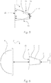
- FIG. 6 shows a schematic representation of a vehicle headlight 2 with a lighting module 1 according to the invention.
- the vehicle headlight 2 comprises a lighting module 1 according to the invention, a laser light source 7 for exciting the lighting module 1 and a projection lens 8 for imaging the light emitted by the lighting module 1 to a light located in front of the vehicle headlight 2 Area.
- the light exit surface 4b has a form adapted to the field curvature E of the projection lens 8, so that each point on the light exit surface 4b is imaged by the projection lens 8 with the same imaging properties.
Landscapes
- Engineering & Computer Science (AREA)
- General Engineering & Computer Science (AREA)
- Physics & Mathematics (AREA)
- Optics & Photonics (AREA)
- Non-Portable Lighting Devices Or Systems Thereof (AREA)
Claims (7)
- Phare de véhicule (2) comportant un module d'éclairage (1), dans lequel le module d'éclairage (1) présente au moins un élément d'éclairage (3) excitable par éclairage avec une lumière laser pour l'émission de lumière visible et au moins un élément de support transparent (4), dans lequel l'élément de support (4) présente au moins une surface d'entrée de lumière (4a) et au moins une surface de sortie de lumière (4b) opposée à la surface d'entrée de lumière (4a), dans lequel ledit au moins un élément d'éclairage (3) est disposé sur ladite au moins une surface d'entrée de lumière (4a) de l'élément de support (4), pour l'irradiation de lumière dans la surface d'entrée de lumière (4a), dans lequela) ladite au moins une surface de sortie de lumière (4b) de l'élément de support (4) est délimitée par un masque opaque entourant la surface de sortie de lumière (4b), oub) ladite au moins une surface de sortie de lumière (4b) s'étend jusqu'à des surfaces latérales (6a à 6d) de l'élément de support (4), au moins une surface latérale (6b) présentant deux parties latérales (6b', 6b") adjacentes l'une à l'autre, qui sont inclinées l'une par rapport à l'autre pour la formation d'une ligne de coupure clair-obscur,dans lequel le phare présente en outre une source de lumière laser (7) pour l'excitation de l'élément d'éclairage (3) et une lentille de projection (8), en particulier une lentille de projection asphérique, pour la formation d'une image de la lumière rayonnée par le module d'éclairage (1) sur une région se trouvant devant le phare de véhicule (2),
caractérisé par le fait que
ladite au moins une surface de sortie de lumière (4b) du module d'éclairage (1) présente un profil adapté à la courbure (E) du champ d'image de la lentille de projection (8). - Phare de véhicule (2) selon la revendication 1, caractérisé par le fait que l'élément de support (4) est fait de verre.
- Phare de véhicule (2) selon l'une des revendications 1 ou 2, caractérisé par le fait que ladite au moins une surface d'entrée de lumière (4a) et ladite au moins une surface de sortie de lumière (4b) sont parallèles l'une à l'autre.
- Phare de véhicule (2) selon la revendication 3, caractérisé par le fait que le rapport de la surface d'entrée de lumière (4a) à la surface de sortie de lumière (4b) se situe entre 1:1 et 1:10, le rapport de la valeur de la surface de sortie de lumière (4b) mesurée en mm2 à la valeur de la distance entre la surface d'entrée de lumière et la surface de sortie de lumière (4b) mesurée en mm est inférieure à 2:1, et le rapport de la valeur de la surface d'entrée de lumière (4a) mesurée en mm2 à la valeur de la distance entre la surface d'entrée de lumière et la surface de sortie de lumière (4b) mesurée en mm est inférieure à 1:2.
- Phare de véhicule (2) selon l'une des revendications 1 à 4, caractérisé par le fait que l'élément de support (4) est une plaque à faces planes et parallèles, qui présente, de préférence, une épaisseur d'au moins 2,2 mm.
- Phare de véhicule (2) selon l'une des revendications 1 à 5, caractérisé par le fait que le masque (5) est fait d'une couche de laque, d'un polymère ou d'un revêtement métallique.
- Phare de véhicule (2) selon l'une des revendications 1 à 6, caractérisé par le fait que le masque (5) limite la surface de sortie de lumière (4b) à une forme géométrique sensiblement hexagonale, laquelle est formée d'une surface rectangulaire et d'une surface trapézoïdale posée sur une moitié de la surface rectangulaire, une ligne latérale de la surface trapézoïdale prolongeant en alignement une ligne latérale de la surface rectangulaire.
Applications Claiming Priority (2)
| Application Number | Priority Date | Filing Date | Title |
|---|---|---|---|
| ATA50573/2015A AT517409B1 (de) | 2015-06-30 | 2015-06-30 | Leuchtmodul für einen Fahrzeugscheinwerfer sowie Fahrzeugscheinwerfer |
| PCT/AT2016/050189 WO2017000005A1 (fr) | 2015-06-30 | 2016-06-09 | Module d'éclairage pour un phare de véhicule |
Publications (2)
| Publication Number | Publication Date |
|---|---|
| EP3317580A1 EP3317580A1 (fr) | 2018-05-09 |
| EP3317580B1 true EP3317580B1 (fr) | 2019-04-10 |
Family
ID=56235510
Family Applications (1)
| Application Number | Title | Priority Date | Filing Date |
|---|---|---|---|
| EP16732218.9A Active EP3317580B1 (fr) | 2015-06-30 | 2016-06-09 | Module d'éclairage pour un phare de véhicule |
Country Status (6)
| Country | Link |
|---|---|
| US (1) | US10371335B2 (fr) |
| EP (1) | EP3317580B1 (fr) |
| JP (1) | JP2018519641A (fr) |
| CN (1) | CN107787426B (fr) |
| AT (1) | AT517409B1 (fr) |
| WO (1) | WO2017000005A1 (fr) |
Families Citing this family (5)
| Publication number | Priority date | Publication date | Assignee | Title |
|---|---|---|---|---|
| FR3071032B1 (fr) * | 2017-09-12 | 2020-10-02 | Valeo Vision | Dispositif lumineux pour l'eclairage de la route, la signalisation ou l'eclairage interieur |
| CN110274210B (zh) * | 2018-03-15 | 2021-08-20 | 株式会社小糸制作所 | 车辆用前照灯 |
| CN112601912A (zh) * | 2018-09-07 | 2021-04-02 | 富士胶片株式会社 | 车辆用前照灯单元、前照灯用遮光膜、前照灯用遮光膜的制造方法 |
| FR3085739B1 (fr) * | 2018-09-12 | 2021-06-25 | Valeo Vision | Module lumineux pour projecteur de vehicule automobile |
| KR102743644B1 (ko) * | 2019-03-29 | 2024-12-18 | 후지필름 가부시키가이샤 | 조성물, 차광막, 컬러 필터, 광학 소자, 센서, 고체 촬상 소자, 헤드라이트 유닛 |
Family Cites Families (21)
| Publication number | Priority date | Publication date | Assignee | Title |
|---|---|---|---|---|
| US2597735A (en) * | 1946-09-13 | 1952-05-20 | Sunbeam Corp | Lawn mower |
| JP3941234B2 (ja) | 1998-06-15 | 2007-07-04 | 市光工業株式会社 | 車両用前照灯装置 |
| JP4140042B2 (ja) * | 2003-09-17 | 2008-08-27 | スタンレー電気株式会社 | 蛍光体を用いたled光源装置及びled光源装置を用いた車両前照灯 |
| JP4339156B2 (ja) * | 2004-03-18 | 2009-10-07 | 株式会社小糸製作所 | 車両用灯具ユニット |
| EP2068068B1 (fr) | 2007-12-07 | 2013-11-20 | Stanley Electric Co., Ltd. | Phare de véhicule |
| JP5447763B2 (ja) | 2008-03-27 | 2014-03-19 | スタンレー電気株式会社 | 車両前照灯 |
| JP2011222260A (ja) | 2010-04-08 | 2011-11-04 | Sharp Corp | 発光装置、照明装置、車両用前照灯および投影装置 |
| JP5112476B2 (ja) | 2010-06-28 | 2013-01-09 | シャープ株式会社 | 発光体、発光装置、照明装置および車両用前照灯 |
| CN102313166B (zh) * | 2010-05-17 | 2015-01-14 | 夏普株式会社 | 发光体、发光装置、照明装置以及车辆用前照灯 |
| WO2012005686A1 (fr) | 2010-07-05 | 2012-01-12 | I3 Lab Pte Ltd | Phare d'automobile à del comprenant un dispositif de tunnel de lumière |
| JP5352686B2 (ja) | 2011-06-24 | 2013-11-27 | シャープ株式会社 | 投光装置、投光ユニットおよび集光部材 |
| JP5883623B2 (ja) | 2011-11-22 | 2016-03-15 | スタンレー電気株式会社 | レーザ光源装置 |
| AT512589B1 (de) * | 2012-03-12 | 2014-06-15 | Zizala Lichtsysteme Gmbh | Lichtleitelement für einen Laser-Fahrzeugscheinwerfer sowie Fahrzeugscheinwerfer |
| JP2013196818A (ja) | 2012-03-16 | 2013-09-30 | Stanley Electric Co Ltd | 発光装置及び車両用灯具 |
| DE102012206970A1 (de) | 2012-04-26 | 2013-10-31 | Osram Gmbh | Optische vorrichtung und beleuchtungseinrichtung |
| JP2013242996A (ja) * | 2012-05-18 | 2013-12-05 | Koito Mfg Co Ltd | 車両用前照灯 |
| DE102012223854A1 (de) * | 2012-12-19 | 2014-06-26 | Osram Gmbh | Remote-Phosphor-Konvertereinrichtung |
| DE102013200521B4 (de) * | 2013-01-15 | 2024-03-21 | Automotive Lighting Reutlingen Gmbh | Primäroptikeinrichtung für KFZ-Schweinwerfer mit Laserlichtquelle, schichtartigem Photolumineszenzelement, Lichtleitelement und Reflexionsflächen für Licht des Photolumineszenzelements und entsprechender KFZ-Scheinwerfer |
| US20160084462A1 (en) | 2013-04-26 | 2016-03-24 | Mitsubishi Electric Corporation | Vehicle headlight module, vehicle headlight unit, and vehicle headlight device |
| JP6271216B2 (ja) | 2013-10-29 | 2018-01-31 | シャープ株式会社 | 発光ユニットおよび照明装置 |
| AT514967B1 (de) * | 2013-10-25 | 2015-08-15 | Zizala Lichtsysteme Gmbh | Mikroprojektions-Lichtmodul für einen Kraftfahrzeugscheinwerfer |
-
2015
- 2015-06-30 AT ATA50573/2015A patent/AT517409B1/de not_active IP Right Cessation
-
2016
- 2016-06-09 CN CN201680039048.0A patent/CN107787426B/zh active Active
- 2016-06-09 JP JP2017568038A patent/JP2018519641A/ja active Pending
- 2016-06-09 EP EP16732218.9A patent/EP3317580B1/fr active Active
- 2016-06-09 WO PCT/AT2016/050189 patent/WO2017000005A1/fr not_active Ceased
- 2016-06-09 US US15/738,340 patent/US10371335B2/en active Active
Non-Patent Citations (1)
| Title |
|---|
| None * |
Also Published As
| Publication number | Publication date |
|---|---|
| US20180180239A1 (en) | 2018-06-28 |
| WO2017000005A1 (fr) | 2017-01-05 |
| CN107787426A (zh) | 2018-03-09 |
| EP3317580A1 (fr) | 2018-05-09 |
| AT517409B1 (de) | 2017-06-15 |
| AT517409A1 (de) | 2017-01-15 |
| US10371335B2 (en) | 2019-08-06 |
| JP2018519641A (ja) | 2018-07-19 |
| CN107787426B (zh) | 2021-01-26 |
Similar Documents
| Publication | Publication Date | Title |
|---|---|---|
| EP3803196B1 (fr) | Module d'éclairage pour un phare de véhicule automobile | |
| EP2893249B1 (fr) | Unité d'éclairage destinée à un projecteur | |
| DE102011012297B4 (de) | Beleuchtungsvorrichtung | |
| DE102008005488B4 (de) | Scheinwerfer für Fahrzeuge | |
| EP3317580B1 (fr) | Module d'éclairage pour un phare de véhicule | |
| DE102013214116C5 (de) | Scheinwerfer für ein blendungsfreies Fernlicht | |
| EP3473918B1 (fr) | Dispositif d'éclairage pour un phare de véhicule automobile | |
| DE102013102553B4 (de) | Vorrichtung zur Homogenisierung von Laserstrahlung | |
| DE102013110345B4 (de) | Beleuchtungsvorrichtung für Fahrzeuge, die mindestens zwei Lichtmodule mit sich kreuzenden Lichtwegen aufweist | |
| DE102015219211B4 (de) | Lichtmodul für eine Kfz-Beleuchtungseinrichtung | |
| DE102014100904A1 (de) | Beleuchtungsvorrichtung für Fahrzeuge | |
| WO2018132852A1 (fr) | Dispositif d'éclairage pour un phare de véhicule automobile | |
| EP2871411B2 (fr) | Élément optique pour un dispositif d'éclairage, et dispositif d'éclairage | |
| EP3292346B1 (fr) | Phare pour véhicules automobiles | |
| EP3461687B1 (fr) | Dispositif de guide de lumière d'un véhicule automobile et lampe de véhicule automobile muni d'un tel dispositif de guide de lumière | |
| DE102004008296A1 (de) | Scheinwerferlinse und Scheinwerfer | |
| EP2352045B1 (fr) | Agencement doté d'un élément de guidage de la lumière et d'un élément réflecteur | |
| EP3056802B1 (fr) | Dispositif d'eclairage d'un module de phare d'un vehicule automobile et procede de fonctionnement d'un dispositif d'eclairage | |
| WO2017174659A1 (fr) | Source de lumière pour dispositif d'éclairage et dispositif d'éclairage équipé d'une telle source de lumière | |
| DE102015218535A1 (de) | Lasermodul und Beleuchtungsvorrichtung mit einem Lasermodul | |
| WO2020083668A1 (fr) | Dispositif d'éclairage pour véhicules | |
| EP3126736A1 (fr) | Dispositif d'éclairage destiné à un véhicule automobile | |
| DE102023121857A1 (de) | Beleuchtungsvorrichtung für ein Kraftfahrzeug | |
| DE102021133748A1 (de) | Laservorrichtung | |
| EP2325084A1 (fr) | Lampe pour un véhicule, notamment un avion |
Legal Events
| Date | Code | Title | Description |
|---|---|---|---|
| STAA | Information on the status of an ep patent application or granted ep patent |
Free format text: STATUS: THE INTERNATIONAL PUBLICATION HAS BEEN MADE |
|
| PUAI | Public reference made under article 153(3) epc to a published international application that has entered the european phase |
Free format text: ORIGINAL CODE: 0009012 |
|
| STAA | Information on the status of an ep patent application or granted ep patent |
Free format text: STATUS: REQUEST FOR EXAMINATION WAS MADE |
|
| 17P | Request for examination filed |
Effective date: 20171127 |
|
| AK | Designated contracting states |
Kind code of ref document: A1 Designated state(s): AL AT BE BG CH CY CZ DE DK EE ES FI FR GB GR HR HU IE IS IT LI LT LU LV MC MK MT NL NO PL PT RO RS SE SI SK SM TR |
|
| AX | Request for extension of the european patent |
Extension state: BA ME |
|
| REG | Reference to a national code |
Ref country code: DE Ref legal event code: R079 Ref document number: 502016004155 Country of ref document: DE Free format text: PREVIOUS MAIN CLASS: F21S0008100000 Ipc: F21S0041140000 |
|
| DAV | Request for validation of the european patent (deleted) | ||
| DAX | Request for extension of the european patent (deleted) | ||
| RIC1 | Information provided on ipc code assigned before grant |
Ipc: F21S 41/24 20180101ALI20180927BHEP Ipc: F21S 41/47 20180101ALI20180927BHEP Ipc: F21S 41/20 20180101ALI20180927BHEP Ipc: F21S 41/176 20180101ALI20180927BHEP Ipc: F21S 41/255 20180101ALI20180927BHEP Ipc: F21S 41/14 20180101AFI20180927BHEP Ipc: F21S 41/16 20180101ALI20180927BHEP |
|
| GRAP | Despatch of communication of intention to grant a patent |
Free format text: ORIGINAL CODE: EPIDOSNIGR1 |
|
| STAA | Information on the status of an ep patent application or granted ep patent |
Free format text: STATUS: GRANT OF PATENT IS INTENDED |
|
| INTG | Intention to grant announced |
Effective date: 20181102 |
|
| GRAS | Grant fee paid |
Free format text: ORIGINAL CODE: EPIDOSNIGR3 |
|
| GRAA | (expected) grant |
Free format text: ORIGINAL CODE: 0009210 |
|
| STAA | Information on the status of an ep patent application or granted ep patent |
Free format text: STATUS: THE PATENT HAS BEEN GRANTED |
|
| AK | Designated contracting states |
Kind code of ref document: B1 Designated state(s): AL AT BE BG CH CY CZ DE DK EE ES FI FR GB GR HR HU IE IS IT LI LT LU LV MC MK MT NL NO PL PT RO RS SE SI SK SM TR |
|
| REG | Reference to a national code |
Ref country code: GB Ref legal event code: FG4D Free format text: NOT ENGLISH |
|
| REG | Reference to a national code |
Ref country code: CH Ref legal event code: EP Ref country code: AT Ref legal event code: REF Ref document number: 1119162 Country of ref document: AT Kind code of ref document: T Effective date: 20190415 |
|
| REG | Reference to a national code |
Ref country code: IE Ref legal event code: FG4D Free format text: LANGUAGE OF EP DOCUMENT: GERMAN |
|
| REG | Reference to a national code |
Ref country code: DE Ref legal event code: R096 Ref document number: 502016004155 Country of ref document: DE |
|
| REG | Reference to a national code |
Ref country code: NL Ref legal event code: MP Effective date: 20190410 |
|
| REG | Reference to a national code |
Ref country code: LT Ref legal event code: MG4D |
|
| PG25 | Lapsed in a contracting state [announced via postgrant information from national office to epo] |
Ref country code: NL Free format text: LAPSE BECAUSE OF FAILURE TO SUBMIT A TRANSLATION OF THE DESCRIPTION OR TO PAY THE FEE WITHIN THE PRESCRIBED TIME-LIMIT Effective date: 20190410 |
|
| PG25 | Lapsed in a contracting state [announced via postgrant information from national office to epo] |
Ref country code: SE Free format text: LAPSE BECAUSE OF FAILURE TO SUBMIT A TRANSLATION OF THE DESCRIPTION OR TO PAY THE FEE WITHIN THE PRESCRIBED TIME-LIMIT Effective date: 20190410 Ref country code: HR Free format text: LAPSE BECAUSE OF FAILURE TO SUBMIT A TRANSLATION OF THE DESCRIPTION OR TO PAY THE FEE WITHIN THE PRESCRIBED TIME-LIMIT Effective date: 20190410 Ref country code: LT Free format text: LAPSE BECAUSE OF FAILURE TO SUBMIT A TRANSLATION OF THE DESCRIPTION OR TO PAY THE FEE WITHIN THE PRESCRIBED TIME-LIMIT Effective date: 20190410 Ref country code: ES Free format text: LAPSE BECAUSE OF FAILURE TO SUBMIT A TRANSLATION OF THE DESCRIPTION OR TO PAY THE FEE WITHIN THE PRESCRIBED TIME-LIMIT Effective date: 20190410 Ref country code: NO Free format text: LAPSE BECAUSE OF FAILURE TO SUBMIT A TRANSLATION OF THE DESCRIPTION OR TO PAY THE FEE WITHIN THE PRESCRIBED TIME-LIMIT Effective date: 20190710 Ref country code: PT Free format text: LAPSE BECAUSE OF FAILURE TO SUBMIT A TRANSLATION OF THE DESCRIPTION OR TO PAY THE FEE WITHIN THE PRESCRIBED TIME-LIMIT Effective date: 20190910 Ref country code: AL Free format text: LAPSE BECAUSE OF FAILURE TO SUBMIT A TRANSLATION OF THE DESCRIPTION OR TO PAY THE FEE WITHIN THE PRESCRIBED TIME-LIMIT Effective date: 20190410 Ref country code: FI Free format text: LAPSE BECAUSE OF FAILURE TO SUBMIT A TRANSLATION OF THE DESCRIPTION OR TO PAY THE FEE WITHIN THE PRESCRIBED TIME-LIMIT Effective date: 20190410 |
|
| PG25 | Lapsed in a contracting state [announced via postgrant information from national office to epo] |
Ref country code: PL Free format text: LAPSE BECAUSE OF FAILURE TO SUBMIT A TRANSLATION OF THE DESCRIPTION OR TO PAY THE FEE WITHIN THE PRESCRIBED TIME-LIMIT Effective date: 20190410 Ref country code: BG Free format text: LAPSE BECAUSE OF FAILURE TO SUBMIT A TRANSLATION OF THE DESCRIPTION OR TO PAY THE FEE WITHIN THE PRESCRIBED TIME-LIMIT Effective date: 20190710 Ref country code: RS Free format text: LAPSE BECAUSE OF FAILURE TO SUBMIT A TRANSLATION OF THE DESCRIPTION OR TO PAY THE FEE WITHIN THE PRESCRIBED TIME-LIMIT Effective date: 20190410 Ref country code: LV Free format text: LAPSE BECAUSE OF FAILURE TO SUBMIT A TRANSLATION OF THE DESCRIPTION OR TO PAY THE FEE WITHIN THE PRESCRIBED TIME-LIMIT Effective date: 20190410 Ref country code: GR Free format text: LAPSE BECAUSE OF FAILURE TO SUBMIT A TRANSLATION OF THE DESCRIPTION OR TO PAY THE FEE WITHIN THE PRESCRIBED TIME-LIMIT Effective date: 20190711 |
|
| PG25 | Lapsed in a contracting state [announced via postgrant information from national office to epo] |
Ref country code: IS Free format text: LAPSE BECAUSE OF FAILURE TO SUBMIT A TRANSLATION OF THE DESCRIPTION OR TO PAY THE FEE WITHIN THE PRESCRIBED TIME-LIMIT Effective date: 20190810 |
|
| REG | Reference to a national code |
Ref country code: DE Ref legal event code: R097 Ref document number: 502016004155 Country of ref document: DE |
|
| PG25 | Lapsed in a contracting state [announced via postgrant information from national office to epo] |
Ref country code: DK Free format text: LAPSE BECAUSE OF FAILURE TO SUBMIT A TRANSLATION OF THE DESCRIPTION OR TO PAY THE FEE WITHIN THE PRESCRIBED TIME-LIMIT Effective date: 20190410 Ref country code: MC Free format text: LAPSE BECAUSE OF FAILURE TO SUBMIT A TRANSLATION OF THE DESCRIPTION OR TO PAY THE FEE WITHIN THE PRESCRIBED TIME-LIMIT Effective date: 20190410 Ref country code: RO Free format text: LAPSE BECAUSE OF FAILURE TO SUBMIT A TRANSLATION OF THE DESCRIPTION OR TO PAY THE FEE WITHIN THE PRESCRIBED TIME-LIMIT Effective date: 20190410 Ref country code: SK Free format text: LAPSE BECAUSE OF FAILURE TO SUBMIT A TRANSLATION OF THE DESCRIPTION OR TO PAY THE FEE WITHIN THE PRESCRIBED TIME-LIMIT Effective date: 20190410 Ref country code: CZ Free format text: LAPSE BECAUSE OF FAILURE TO SUBMIT A TRANSLATION OF THE DESCRIPTION OR TO PAY THE FEE WITHIN THE PRESCRIBED TIME-LIMIT Effective date: 20190410 Ref country code: EE Free format text: LAPSE BECAUSE OF FAILURE TO SUBMIT A TRANSLATION OF THE DESCRIPTION OR TO PAY THE FEE WITHIN THE PRESCRIBED TIME-LIMIT Effective date: 20190410 |
|
| REG | Reference to a national code |
Ref country code: CH Ref legal event code: PL |
|
| PLBE | No opposition filed within time limit |
Free format text: ORIGINAL CODE: 0009261 |
|
| STAA | Information on the status of an ep patent application or granted ep patent |
Free format text: STATUS: NO OPPOSITION FILED WITHIN TIME LIMIT |
|
| PG25 | Lapsed in a contracting state [announced via postgrant information from national office to epo] |
Ref country code: IT Free format text: LAPSE BECAUSE OF FAILURE TO SUBMIT A TRANSLATION OF THE DESCRIPTION OR TO PAY THE FEE WITHIN THE PRESCRIBED TIME-LIMIT Effective date: 20190410 Ref country code: SM Free format text: LAPSE BECAUSE OF FAILURE TO SUBMIT A TRANSLATION OF THE DESCRIPTION OR TO PAY THE FEE WITHIN THE PRESCRIBED TIME-LIMIT Effective date: 20190410 |
|
| 26N | No opposition filed |
Effective date: 20200113 |
|
| REG | Reference to a national code |
Ref country code: BE Ref legal event code: MM Effective date: 20190630 |
|
| PG25 | Lapsed in a contracting state [announced via postgrant information from national office to epo] |
Ref country code: TR Free format text: LAPSE BECAUSE OF FAILURE TO SUBMIT A TRANSLATION OF THE DESCRIPTION OR TO PAY THE FEE WITHIN THE PRESCRIBED TIME-LIMIT Effective date: 20190410 |
|
| PG25 | Lapsed in a contracting state [announced via postgrant information from national office to epo] |
Ref country code: IE Free format text: LAPSE BECAUSE OF NON-PAYMENT OF DUE FEES Effective date: 20190609 |
|
| PG25 | Lapsed in a contracting state [announced via postgrant information from national office to epo] |
Ref country code: CH Free format text: LAPSE BECAUSE OF NON-PAYMENT OF DUE FEES Effective date: 20190630 Ref country code: BE Free format text: LAPSE BECAUSE OF NON-PAYMENT OF DUE FEES Effective date: 20190630 Ref country code: LU Free format text: LAPSE BECAUSE OF NON-PAYMENT OF DUE FEES Effective date: 20190609 Ref country code: SI Free format text: LAPSE BECAUSE OF FAILURE TO SUBMIT A TRANSLATION OF THE DESCRIPTION OR TO PAY THE FEE WITHIN THE PRESCRIBED TIME-LIMIT Effective date: 20190410 Ref country code: LI Free format text: LAPSE BECAUSE OF NON-PAYMENT OF DUE FEES Effective date: 20190630 |
|
| GBPC | Gb: european patent ceased through non-payment of renewal fee |
Effective date: 20200609 |
|
| PG25 | Lapsed in a contracting state [announced via postgrant information from national office to epo] |
Ref country code: GB Free format text: LAPSE BECAUSE OF NON-PAYMENT OF DUE FEES Effective date: 20200609 |
|
| PG25 | Lapsed in a contracting state [announced via postgrant information from national office to epo] |
Ref country code: CY Free format text: LAPSE BECAUSE OF FAILURE TO SUBMIT A TRANSLATION OF THE DESCRIPTION OR TO PAY THE FEE WITHIN THE PRESCRIBED TIME-LIMIT Effective date: 20190410 |
|
| PG25 | Lapsed in a contracting state [announced via postgrant information from national office to epo] |
Ref country code: MT Free format text: LAPSE BECAUSE OF FAILURE TO SUBMIT A TRANSLATION OF THE DESCRIPTION OR TO PAY THE FEE WITHIN THE PRESCRIBED TIME-LIMIT Effective date: 20190410 Ref country code: HU Free format text: LAPSE BECAUSE OF FAILURE TO SUBMIT A TRANSLATION OF THE DESCRIPTION OR TO PAY THE FEE WITHIN THE PRESCRIBED TIME-LIMIT; INVALID AB INITIO Effective date: 20160609 |
|
| PG25 | Lapsed in a contracting state [announced via postgrant information from national office to epo] |
Ref country code: MK Free format text: LAPSE BECAUSE OF FAILURE TO SUBMIT A TRANSLATION OF THE DESCRIPTION OR TO PAY THE FEE WITHIN THE PRESCRIBED TIME-LIMIT Effective date: 20190410 |
|
| REG | Reference to a national code |
Ref country code: AT Ref legal event code: MM01 Ref document number: 1119162 Country of ref document: AT Kind code of ref document: T Effective date: 20210609 |
|
| PG25 | Lapsed in a contracting state [announced via postgrant information from national office to epo] |
Ref country code: AT Free format text: LAPSE BECAUSE OF NON-PAYMENT OF DUE FEES Effective date: 20210609 |
|
| P01 | Opt-out of the competence of the unified patent court (upc) registered |
Effective date: 20230528 |
|
| PGFP | Annual fee paid to national office [announced via postgrant information from national office to epo] |
Ref country code: DE Payment date: 20250618 Year of fee payment: 10 |
|
| PGFP | Annual fee paid to national office [announced via postgrant information from national office to epo] |
Ref country code: FR Payment date: 20250618 Year of fee payment: 10 |
|
| REG | Reference to a national code |
Ref country code: DE Ref legal event code: R084 Ref document number: 502016004155 Country of ref document: DE |