EP3292346B1 - Phare pour véhicules automobiles - Google Patents
Phare pour véhicules automobiles Download PDFInfo
- Publication number
- EP3292346B1 EP3292346B1 EP16724585.1A EP16724585A EP3292346B1 EP 3292346 B1 EP3292346 B1 EP 3292346B1 EP 16724585 A EP16724585 A EP 16724585A EP 3292346 B1 EP3292346 B1 EP 3292346B1
- Authority
- EP
- European Patent Office
- Prior art keywords
- motor vehicle
- light
- optical
- vehicle headlamp
- light spot
- Prior art date
- Legal status (The legal status is an assumption and is not a legal conclusion. Google has not performed a legal analysis and makes no representation as to the accuracy of the status listed.)
- Active
Links
Images



Classifications
-
- F—MECHANICAL ENGINEERING; LIGHTING; HEATING; WEAPONS; BLASTING
- F21—LIGHTING
- F21S—NON-PORTABLE LIGHTING DEVICES; SYSTEMS THEREOF; VEHICLE LIGHTING DEVICES SPECIALLY ADAPTED FOR VEHICLE EXTERIORS
- F21S45/00—Arrangements within vehicle lighting devices specially adapted for vehicle exteriors, for purposes other than emission or distribution of light
- F21S45/10—Protection of lighting devices
-
- F—MECHANICAL ENGINEERING; LIGHTING; HEATING; WEAPONS; BLASTING
- F21—LIGHTING
- F21S—NON-PORTABLE LIGHTING DEVICES; SYSTEMS THEREOF; VEHICLE LIGHTING DEVICES SPECIALLY ADAPTED FOR VEHICLE EXTERIORS
- F21S41/00—Illuminating devices specially adapted for vehicle exteriors, e.g. headlamps
- F21S41/20—Illuminating devices specially adapted for vehicle exteriors, e.g. headlamps characterised by refractors, transparent cover plates, light guides or filters
- F21S41/25—Projection lenses
- F21S41/275—Lens surfaces, e.g. coatings or surface structures
-
- B—PERFORMING OPERATIONS; TRANSPORTING
- B60—VEHICLES IN GENERAL
- B60Q—ARRANGEMENT OF SIGNALLING OR LIGHTING DEVICES, THE MOUNTING OR SUPPORTING THEREOF OR CIRCUITS THEREFOR, FOR VEHICLES IN GENERAL
- B60Q1/00—Arrangement of optical signalling or lighting devices, the mounting or supporting thereof or circuits therefor
- B60Q1/0005—Devices preventing the lights from becoming dirty or damaged, e.g. protection grids or cleaning by air flow
-
- F—MECHANICAL ENGINEERING; LIGHTING; HEATING; WEAPONS; BLASTING
- F21—LIGHTING
- F21S—NON-PORTABLE LIGHTING DEVICES; SYSTEMS THEREOF; VEHICLE LIGHTING DEVICES SPECIALLY ADAPTED FOR VEHICLE EXTERIORS
- F21S41/00—Illuminating devices specially adapted for vehicle exteriors, e.g. headlamps
- F21S41/20—Illuminating devices specially adapted for vehicle exteriors, e.g. headlamps characterised by refractors, transparent cover plates, light guides or filters
- F21S41/25—Projection lenses
- F21S41/255—Lenses with a front view of circular or truncated circular outline
-
- F—MECHANICAL ENGINEERING; LIGHTING; HEATING; WEAPONS; BLASTING
- F21—LIGHTING
- F21S—NON-PORTABLE LIGHTING DEVICES; SYSTEMS THEREOF; VEHICLE LIGHTING DEVICES SPECIALLY ADAPTED FOR VEHICLE EXTERIORS
- F21S41/00—Illuminating devices specially adapted for vehicle exteriors, e.g. headlamps
- F21S41/20—Illuminating devices specially adapted for vehicle exteriors, e.g. headlamps characterised by refractors, transparent cover plates, light guides or filters
- F21S41/28—Cover glass
Definitions
- the invention relates to a motor vehicle headlight according to the preamble of claim 1.
- the invention relates to a motor vehicle with at least one, preferably two, such vehicle headlights.
- Light imaging systems containing lenses are used in motor vehicle headlights. These lenses bundle parallel sunlight coming in from the outside and direct it to focal points on a motor vehicle headlight element. Depending on the position of the sun relative to the motor vehicle headlight, the inclination of the vehicle or the nature of the motor vehicle headlight element material, the energy input of the sunlight, measured by the irradiance in W/m 2 , can be too high on the motor vehicle headlight element and lead to the melting of motor vehicle headlight elements. As a result, at least the surfaces of the motor vehicle headlight elements are damaged and unsightly, and mechanical instabilities of the motor vehicle headlight elements and/or outgassing can also occur. In this case, this is referred to as the magnifying glass effect.
- the motor vehicle headlights of the type mentioned above are known in the state of the art. Among them, some motor vehicle headlights are already known that offer a solution to reduce the magnifying glass effect.
- DE 19803986 A1 discloses the use of optical deflection means on the outside of the lens, which are intended to substantially prevent the light from penetrating into the interior of the lens.
- These optical deflection means are in many cases achieved by sandblasting or granite blasting the lens surface and usually require an additional element that prevents the light generated by the light source arranged in the headlight from falling on the roughened outer surface of the lens. This solution effectively reduces the numerical aperture of the lens and can affect the light distributions generated by the motor vehicle headlight.
- JP 2014063604 A a motor vehicle headlight, which comprises a light source having a light-emitting surface and an aspherical lens, wherein the lens projects light emitted by the light source arranged in the motor vehicle headlight in front of the motor vehicle headlight in the form of a low beam distribution.
- the lens has an area 8 which is not illuminated by the light emitted by the light source and onto which the sunlight falls. This area is used exclusively to reduce the magnifying glass effect by diffusely scattering the sunlight.
- the disadvantage of this approach is the reduction of the refractive area of the lens and can only be used with low beam modules. In addition, the effect achieved with the area depends considerably on the position of the sun.
- the lighting device arranged in the motor vehicle headlight comprises one, two or more light sources which emit/emit the light to produce the predetermined light distribution, wherein preferably the light source/light sources are assigned a reflector, in particular an ellipsoidal free-form reflector, and/or an auxiliary optic, preferably an imaging lens arrangement, and/or a diaphragm.
- the light source(s) is/are designed as an HID lamp, i.e., a xenon gas discharge lamp, for example according to standard ECE-R99, and/or one, two or more LEDs, which may have the same or different designs, and/or an incandescent lamp, for example a filament lamp according to standard ECE-R37.
- HID lamp i.e., a xenon gas discharge lamp, for example according to standard ECE-R99
- LEDs which may have the same or different designs
- an incandescent lamp for example a filament lamp according to standard ECE-R37.
- the light coming in from outside can be imagined as a number of parallel light beams. When they hit an area of a conventional lens, many of these light beams are refracted to a focal point. This creates a surface area with a high irradiance. Due to the presence of an optical structure according to the invention, which can be applied to one of the lens surfaces, for example, each light beam is refracted to a different focal point, i.e. defocused.
- optical structural elements over at least one, preferably exactly one defined basic structure of at least one, preferably exactly one, of the light imaging system elements.
- the basic structure is designed as a two-dimensional grid and consists of one, two or more defined grid cells.
- the two-dimensional grid essentially forms a structured grid with regular cell geometry.
- the grid cells are designed as regular polygons.
- at least one, preferably exactly one, structural element is arranged on each grid cell.
- the geometric dimensions of the grating cells and the structural elements should be carefully selected.
- optical structural elements are designed substantially identically.
- the optical structural elements have a central elevation in their center.
- the height of the central elevation is 25 micrometers.
- the invention provides that the central elevation is described by a function graph of a continuous real and non-negative function defined on a grid cell.
- the function graph represents a two-dimensional surface.
- the function is designed as a piecewise linear function.
- the function is designed such that the function graph is substantially rotationally symmetrical with respect to a vertical axis passing through the center of the grid cell.
- a vertical section of the function graph along a horizontal line running through the center of the grid cell has a piecewise linear function, wherein this function has at least five linear sections and the extension of the second linear section and the third linear section enclose an angle of rise.
- the optical structural elements have a base area whose extent is 1.0 millimeters.
- the refracted modified light beams must be considered, and it is provided according to the invention that the first modified light beam falls on a first headlight element and illuminates a first modified luminous point and the second modified light beam falls on a second headlight element and illuminates a second modified luminous point.
- the size of the first modified luminous point and/or the second modified luminous point is related to the dimensions of the central elevation, for example with a first angle of rise and/or with a second angle of rise, a plateau diameter and/or a height of the central elevation.
- the size, for example a diameter, of the first modified luminous point and/or of the second modified luminous point is larger than the size, for example a diameter, of an unmodified luminous point.
- the maximum irradiance within the first modified luminous point and/or within the second modified luminous point is lower than the irradiance within the unmodified luminous point.
- the optical structure can be installed in many places in the vehicle headlight.
- the exact position of the optical structure depends on the specific design of the vehicle headlight. In addition to the legal regulations, another requirement must be met when positioning the optical structure.
- the structure must be illuminated by light coming in from outside (in the case of sunlight, regardless of the height of the sun).
- the optical structure on at least one, preferably exactly one surface of a light imaging system element which is designed in the form of a projection lens and/or imaging lens.
- the optical structure is arranged on an entrance surface and/or an exit surface of a light imaging system element which is designed in the form of a projection lens and/or imaging lens.
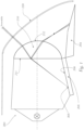
- Fig. 1 schematically shows a conventional vehicle headlight with its most important elements in side section. It shows a lighting device 200, a first motor vehicle headlight element, e.g. a cover, a holder or a design element 204, which can be designed, for example, as a cover separating functional units in the headlight, a second motor vehicle headlight element, e.g.
- a first motor vehicle headlight element e.g. a cover, a holder or a design element 204, which can be designed, for example, as a cover separating functional units in the headlight
- a second motor vehicle headlight element e.g.
- a lens holder for example a printed circuit board / a circuit carrier 205 in the form of a PCB (Printed Circuit Board), on which LEDs are fitted, for example, a light imaging system, which is shown here for the sake of simplicity in the form of a typical imaging lens 210, and a cover plate 220.
- a circuit board for example a printed circuit board / a circuit carrier 205 in the form of a PCB (Printed Circuit Board)
- LEDs for example, a light imaging system, which is shown here for the sake of simplicity in the form of a typical imaging lens 210, and a cover plate 220.
- motor vehicle headlight elements often made of plastic, such as various holders, designs or circuit boards 204, 205. These are usually caused by refraction and/or reflection on the entry surface 211 of an optical element, for example an imaging or projection lens.
- the beam that passes through then falls directly on a motor vehicle headlight element (internal magnifying glass effect), for example on a plastic holder, whereby the reflected beam only hits a motor vehicle headlight element after further refraction on the exit surface of an optical element, e.g. an imaging or projection lens 212 (external magnifying glass effect).
- a high irradiance occurs in a luminous point 305 on the surface 205 of the motor vehicle headlight element, which can far exceed the damage limit of the material.
- the irradiance can reach a value of 75,000 W/m 2 , which exceeds the damage limit of a special plastic material used in motor vehicle headlights, "PBT-GF30 black", of approximately 62,000 W/m 2 , and causes rapid melting of the motor vehicle headlight element.
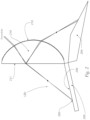
- Fig. 2 shows an imaging lens 210 with an optical structure 215 applied to the exit surface of the lens. Due to the special shape of the structural elements 502, the focal point position is shifted in space. This creates another larger luminous point 350 on one of the motor vehicle headlight elements 204, 205, as shown schematically in Fig. 3
- d or D the diameter of a luminous point
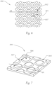
- Fig. 4 shows a perspective view of an enlarged section of an optical structure arranged on the exit surface 215 of a lens, which is applied to a hexagonal basic structure, and an even larger section with a structural element 502.
- the structural element has a central elevation in the form of a truncated cone of a certain height h.
- a "smearing" of the point by the truncated cone-shaped central elevation of the structural element 502 is in Fig. 5
- the illuminated area is a point with a diameter.
- the radiation flux per unit area (radiation flux density) is large.
- the central elevation causes the illuminated area to expand (right image in Fig. 5 ). This reduces the radiation flux density.
- the entire incident radiation energy is redistributed over a larger area, in other words, the original light beam is "defocused" so that defocused light beams LB1 are created.
- FIG. 6 An embodiment of an optical structure is shown in plan view.
- the basic structure 500 consists of hexagonal grid cells 501.
- the structural elements have a rotationally symmetrical central elevation.
- this central elevation is designed as a straight truncated cone with a cover surface 506 and a lateral surface 507 and is arranged on a base surface 505.
- light is incident perpendicularly to the base surface 505, it is refracted at the lateral surfaces and leads to the smearing of the luminous point on a motor vehicle headlight element.
- the degree of smearing depends on the geometric properties of the central elevation of the optical structure element 502.
- Fig. 8 shows a vertical section of the structural element 502 along a horizontal line AA ( Fig. 6 and 7 ).
- the section through the center 510 of the structural element 502 can be described by a graph of a piecewise linear function.
- the function has five linear sections 601, 602, 603, 604, 605.
- the blurring of the luminous point depends on the length P of the middle linear section 603, which is equal to the diameter of the cover surface 506, on the length of the second section 602 and the fourth section 604 and the angle of rise ⁇ of the second linear section 602.
- the invention has been described with reference to a hexagonal basic structure and a substantially flat, rotationally symmetrical central elevation, for which the invention is particularly advantageous.
- the invention can also be used with non-hexagonal basic structures and with differently designed central elevations.
Landscapes
- Engineering & Computer Science (AREA)
- General Engineering & Computer Science (AREA)
- Non-Portable Lighting Devices Or Systems Thereof (AREA)
Claims (8)
- Motor vehicle headlamp, which comprisesan at least partially transparent cover lens (220), in particular in the visible spectral range,at least one lighting device (200),at least one light imaging system (210) associated with the lighting device (200), which images light emitted by at least one light source into an area in front of the lighting device in the form of a predetermined light distribution, whereinat least one optical structure (215) is provided in the motor vehicle headlamp, which optical structure (215) comprises one, two or more optical structural elements (502) and is arranged in the motor vehicle headlamp in such a way that at least some of the light, in particular sunlight, incident on the motor vehicle headlamp from outside in parallel is incident on the optical structure (215) and is scattered by the optical structure when it passes through the optical structure and when it is reflected,wherein the structural elements (502) have a light-scattering effect and are designed such that each structural element (502) modifies a light beam passing through the structural element to form a first modified light beam (LB1) and modifies a light beam reflected by the structural element (502) to form a second modified light beam (LB2), the predetermined light distribution by the optical structure (215) remaining essentially unchanged,
oùle premier faisceau lumineux modifié est incident sur un premier élément de projecteur (205) et éclaire un premier point lumineux modifié (350) et le deuxième faisceau lumineux modifié est incident sur un deuxième élément de projecteur (204) et éclaire un deuxième point lumineux modifié, et dans lequelune taille, par exemple un diamètre (D), du premier point lumineux modifié (350) et du second point lumineux modifié est plus grande qu'une taille, par exemple un diamètre (d), d'un point lumineux non modifié (305), l'éclairement lumineux maximal à l'intérieur du premier point lumineux modifié (350) et à l'intérieur du second point lumineux modifié (450) étant inférieur à l'éclairement lumineux à l'intérieur du point lumineux non modifié (305),et dans lequella structure optique (215) est disposée sur une surface d'entrée (211) et/ou une surface de sortie (212) d'un élément de système d'imagerie lumineuse qui est réalisé sous la forme d'une lentille de projection et/ou d'une lentille d'imagerie (210), et dans lequelles éléments de structure optique (502) présentent une surface de base, etles éléments de structure optique (502) présentent en leur centre une bosse centrale (506), et dans lequell'élévation centrale (506) est décrite par un graphique fonctionnel d'une fonction réelle et non négative continue définie sur une cellule de grille (501), caractérisé en ce que l'extension de la surface de base est de 1,0 millimètre et l'élévation centrale présente une hauteur (h) de 25 micromètres. - Projecteur de véhicule automobile selon la revendication 1, dans lequel le dispositif d'éclairage (200) comprend une, deux ou plusieurs sources lumineuses, un réflecteur, en particulier un réflecteur ellipsoïdal de forme libre, et/ou une optique rapportée, de préférence un agencement de lentilles d'imagerie, et/ou un diaphragme étant de préférence associé à ladite au moins une source lumineuse.
- Projecteur de véhicule automobile selon la revendication 1 ou 2, dans lequel l'au moins une source lumineuse est conçue comme une lampe HID, de préférence une lampe HID selon la norme ECE-R99, et/ou une, deux ou plusieurs LED et/ou une lampe à incandescence, par exemple une lampe à filament selon la norme ECE-R37.
- Projecteur de véhicule automobile selon l'une des revendications 1 à 3, dans lequel les éléments de structure optique (502) sont répartis sur au moins une structure de base (500), de préférence exactement définie, d'au moins un élément de système d'imagerie lumineuse, de préférence exactement un élément de système d'imagerie lumineuse, la structure de base (500) étant par exemple réalisée sous la forme d'un réseau bidimensionnel (503) et étant constituée d'une, deux ou plusieurs cellules de grille (501) définies, la grille bidimensionnelle (503) formant de préférence essentiellement une grille structurée avec une géométrie de cellule régulière et/ou les cellules de grille (501) étant par exemple réalisées sous forme de polygones réguliers, au moins un élément de structure (502), en particulier exactement un, étant de préférence disposé sur chaque cellule de grille (501).
- Projecteur de véhicule automobile selon l'une quelconque des revendications 1 à 4, dans lequel les éléments de structure optique (502) sont réalisés de manière sensiblement identique.
- Projecteur de véhicule automobile selon l'une des revendications 1 à 5, dans lequel la taille du premier point lumineux modifié (350) et/ou du deuxième point lumineux modifié, par exemple un diamètre du point lumineux, est liée aux dimensions du relief central, par exemple à un premier angle de montée (α) et/ou à un deuxième angle de montée, un diamètre de plateau (P) et/ou une hauteur du relief central (h).
- Projecteur de véhicule automobile selon l'une quelconque des revendications 1 à 6, dans lequel la fonction réelle et non négative est telle que le graphe de la fonction est sensiblement à symétrie de révolution par rapport à un axe vertical passant par un centre (510) de la cellule de grille (501), et oùune coupe verticale du graphe fonctionnel le long d'une ligne horizontale (AA) passant par le point central (510) de la cellule de grille (501) présente une fonction linéaire par morceaux, cette fonction présentant au moins cinq sections linéaires (601, 602, 603, 604, 605) et le prolongement de la deuxième section linéaire (602) et la troisième section linéaire (603) comprenant un angle de montée (α).
- Véhicule automobile comportant au moins un, de préférence deux, projecteur(s) de véhicule automobile selon l'une quelconque des revendications 1 à 7.
Applications Claiming Priority (2)
| Application Number | Priority Date | Filing Date | Title |
|---|---|---|---|
| ATA50363/2015A AT517173B1 (de) | 2015-05-06 | 2015-05-06 | Scheinwerfer für Kraftfahrzeuge |
| PCT/AT2016/050120 WO2016176706A1 (fr) | 2015-05-06 | 2016-05-02 | Phare pour véhicules automobiles |
Publications (2)
| Publication Number | Publication Date |
|---|---|
| EP3292346A1 EP3292346A1 (fr) | 2018-03-14 |
| EP3292346B1 true EP3292346B1 (fr) | 2025-02-12 |
Family
ID=56072144
Family Applications (1)
| Application Number | Title | Priority Date | Filing Date |
|---|---|---|---|
| EP16724585.1A Active EP3292346B1 (fr) | 2015-05-06 | 2016-05-02 | Phare pour véhicules automobiles |
Country Status (4)
| Country | Link |
|---|---|
| EP (1) | EP3292346B1 (fr) |
| CN (1) | CN108633297B (fr) |
| AT (1) | AT517173B1 (fr) |
| WO (1) | WO2016176706A1 (fr) |
Families Citing this family (4)
| Publication number | Priority date | Publication date | Assignee | Title |
|---|---|---|---|---|
| JP6932933B2 (ja) * | 2017-01-19 | 2021-09-08 | 市光工業株式会社 | 車両用前照灯 |
| EP3667389B1 (fr) * | 2018-12-11 | 2023-03-15 | ZKW Group GmbH | Dispositif d'éclairage pour un véhicule automobile |
| DE102019130464A1 (de) * | 2019-11-12 | 2021-05-12 | Marelli Automotive Lighting Reutlingen (Germany) GmbH | Kraftfahrzeugscheinwerfer |
| DE102022108112A1 (de) | 2022-04-05 | 2023-10-05 | Marelli Automotive Lighting Reutlingen (Germany) GmbH | Kraftfahrzeugscheinwerfer |
Citations (8)
| Publication number | Priority date | Publication date | Assignee | Title |
|---|---|---|---|---|
| JPH04357602A (ja) * | 1991-09-06 | 1992-12-10 | Nissan Shatai Co Ltd | 車両用灯具 |
| DE19803986A1 (de) * | 1997-02-18 | 1998-08-20 | Valeo Vision | Scheinwerfer in elliptischer Ausführung, insbesondere für Kraftfahrzeuge |
| FR2770617A1 (fr) * | 1997-10-30 | 1999-05-07 | Valeo Vision | Projecteur elliptique pour vehicule automobile dont le faisceau lumineux presente une coupure attenuee |
| DE29912504U1 (de) * | 1999-07-16 | 1999-09-16 | Hella Kg Hueck & Co, 59557 Lippstadt | Scheinwerfer für Fahrzeuge |
| WO2014027020A1 (fr) * | 2012-08-14 | 2014-02-20 | Hella Kgaa Hueck & Co. | Surface optique et dispositif d'éclairage pour véhicules |
| JP2014063604A (ja) * | 2012-09-20 | 2014-04-10 | Ichikoh Ind Ltd | 車両用灯具 |
| WO2015031925A1 (fr) * | 2013-09-03 | 2015-03-12 | Zizala Lichtsysteme Gmbh | Structure optique comprenant une microstructure à fonction de dispersion quadratique |
| US20150103544A1 (en) * | 2013-10-11 | 2015-04-16 | Koito Manufacturing Co., Ltd. | Vehicle lamp |
Family Cites Families (2)
| Publication number | Priority date | Publication date | Assignee | Title |
|---|---|---|---|---|
| FR2983279B1 (fr) * | 2011-11-24 | 2015-08-21 | Valeo Vision | Element opaque et mobile empechant une focalisation des rayons solaires dans un projecteur |
| DE102012101434B4 (de) | 2012-02-23 | 2023-05-04 | HELLA GmbH & Co. KGaA | Linsenhalter zur Aufnahme einer Linse in einem Scheinwerfer |
-
2015
- 2015-05-06 AT ATA50363/2015A patent/AT517173B1/de active
-
2016
- 2016-05-02 CN CN201680025812.9A patent/CN108633297B/zh active Active
- 2016-05-02 EP EP16724585.1A patent/EP3292346B1/fr active Active
- 2016-05-02 WO PCT/AT2016/050120 patent/WO2016176706A1/fr not_active Ceased
Patent Citations (8)
| Publication number | Priority date | Publication date | Assignee | Title |
|---|---|---|---|---|
| JPH04357602A (ja) * | 1991-09-06 | 1992-12-10 | Nissan Shatai Co Ltd | 車両用灯具 |
| DE19803986A1 (de) * | 1997-02-18 | 1998-08-20 | Valeo Vision | Scheinwerfer in elliptischer Ausführung, insbesondere für Kraftfahrzeuge |
| FR2770617A1 (fr) * | 1997-10-30 | 1999-05-07 | Valeo Vision | Projecteur elliptique pour vehicule automobile dont le faisceau lumineux presente une coupure attenuee |
| DE29912504U1 (de) * | 1999-07-16 | 1999-09-16 | Hella Kg Hueck & Co, 59557 Lippstadt | Scheinwerfer für Fahrzeuge |
| WO2014027020A1 (fr) * | 2012-08-14 | 2014-02-20 | Hella Kgaa Hueck & Co. | Surface optique et dispositif d'éclairage pour véhicules |
| JP2014063604A (ja) * | 2012-09-20 | 2014-04-10 | Ichikoh Ind Ltd | 車両用灯具 |
| WO2015031925A1 (fr) * | 2013-09-03 | 2015-03-12 | Zizala Lichtsysteme Gmbh | Structure optique comprenant une microstructure à fonction de dispersion quadratique |
| US20150103544A1 (en) * | 2013-10-11 | 2015-04-16 | Koito Manufacturing Co., Ltd. | Vehicle lamp |
Also Published As
| Publication number | Publication date |
|---|---|
| AT517173B1 (de) | 2017-05-15 |
| CN108633297B (zh) | 2021-11-09 |
| EP3292346A1 (fr) | 2018-03-14 |
| AT517173A1 (de) | 2016-11-15 |
| CN108633297A (zh) | 2018-10-09 |
| WO2016176706A1 (fr) | 2016-11-10 |
Similar Documents
| Publication | Publication Date | Title |
|---|---|---|
| EP3803196B1 (fr) | Module d'éclairage pour un phare de véhicule automobile | |
| EP2893249B1 (fr) | Unité d'éclairage destinée à un projecteur | |
| EP2505910B1 (fr) | Phare de véhicule automobile équipé d'une source lumineuse semi-conductrice | |
| EP3653926B1 (fr) | Dispositif d'éclairage pour un phare de véhicule automobile ainsi que phare de véhicule automobile | |
| EP2837962B1 (fr) | Procédé destiné à calculer des surfaces de lentilles optiques et lentille de projection calculée selon le procédé pour un module d'éclairage d'un phare de véhicule automobile | |
| WO2019158319A1 (fr) | Projecteur de véhicule automobile comprenant un écran de protection pour la protection contre le rayonnement solaire incident | |
| AT517173B1 (de) | Scheinwerfer für Kraftfahrzeuge | |
| EP3524873A1 (fr) | Module lumineux de projection efficace comportant des microprojecteurs pour un phare de véhicule automobile | |
| EP3091273A1 (fr) | Structure optique pour voyant lumineux | |
| EP3317580B1 (fr) | Module d'éclairage pour un phare de véhicule | |
| EP3721134B1 (fr) | Dispositif de projection pour un phare de véhicule automobile | |
| DE102015219211B4 (de) | Lichtmodul für eine Kfz-Beleuchtungseinrichtung | |
| DE102017124392B4 (de) | Fahrzeugscheinwerfer mit einer Blende, die an einem Reflektor reflektiertes Licht zu einem kollimierenden Reflektor lenkt | |
| DE102018201980A1 (de) | Beleuchtungsvorrichtung für ein Kraftfahrzeug | |
| DE102015201856B4 (de) | Kfz-Scheinwerfer | |
| EP3715705A1 (fr) | Module lumineux pour un projecteur de véhicule automobile pourvu de n modules lumineux partiels agencés en une rangée | |
| DE102015222363B4 (de) | Lampenvorrichtung für fahrzeuge | |
| AT519356B1 (de) | Lichtmodul für einen Kraftfahrzeugscheinwerfer | |
| DE102019112343A1 (de) | Kraftfahrzeugleuchte | |
| EP3667389B1 (fr) | Dispositif d'éclairage pour un véhicule automobile | |
| EP3719391B1 (fr) | Module de feu de route partiel pour un phare de véhicule automobile | |
| DE102019125971A1 (de) | Kraftfahrzeugscheinwerfer mit einem Lichtmodul und breit ausgeleuchteter Lichtaustrittslinse | |
| DE102016101730A1 (de) | Lichtmodul einer Beleuchtungseinrichtung eines Kraftfahrzeugs und Beleuchtungseinrichtung mit einem solchen Lichtmodul | |
| DE202016101480U1 (de) | Beleuchtungsvorrichtung für einen Kraftfahrzeugscheinwerfer |
Legal Events
| Date | Code | Title | Description |
|---|---|---|---|
| STAA | Information on the status of an ep patent application or granted ep patent |
Free format text: STATUS: THE INTERNATIONAL PUBLICATION HAS BEEN MADE |
|
| PUAI | Public reference made under article 153(3) epc to a published international application that has entered the european phase |
Free format text: ORIGINAL CODE: 0009012 |
|
| STAA | Information on the status of an ep patent application or granted ep patent |
Free format text: STATUS: REQUEST FOR EXAMINATION WAS MADE |
|
| 17P | Request for examination filed |
Effective date: 20171128 |
|
| AK | Designated contracting states |
Kind code of ref document: A1 Designated state(s): AL AT BE BG CH CY CZ DE DK EE ES FI FR GB GR HR HU IE IS IT LI LT LU LV MC MK MT NL NO PL PT RO RS SE SI SK SM TR |
|
| AX | Request for extension of the european patent |
Extension state: BA ME |
|
| DAV | Request for validation of the european patent (deleted) | ||
| DAX | Request for extension of the european patent (deleted) | ||
| RIC1 | Information provided on ipc code assigned before grant |
Ipc: F21S 8/10 20181130AFI20161111BHEP Ipc: F21V 15/00 20150101ALI20161111BHEP Ipc: F21V 5/00 20180101ALI20161111BHEP |
|
| RIC1 | Information provided on ipc code assigned before grant |
Ipc: F21S 8/10 20060101AFI20161111BHEP Ipc: F21V 15/00 20150101ALI20161111BHEP Ipc: F21V 5/00 20180101ALI20161111BHEP |
|
| RIN1 | Information on inventor provided before grant (corrected) |
Inventor name: PUERSTINGER, JOSEF Inventor name: TAUDT, LUKAS Inventor name: KREMZER, ZBYNEK |
|
| STAA | Information on the status of an ep patent application or granted ep patent |
Free format text: STATUS: EXAMINATION IS IN PROGRESS |
|
| 17Q | First examination report despatched |
Effective date: 20210712 |
|
| REG | Reference to a national code |
Ref country code: DE Ref legal event code: R079 Free format text: PREVIOUS MAIN CLASS: F21S0008100000 Ipc: F21S0045100000 Ref document number: 502016016887 Country of ref document: DE |
|
| GRAP | Despatch of communication of intention to grant a patent |
Free format text: ORIGINAL CODE: EPIDOSNIGR1 |
|
| STAA | Information on the status of an ep patent application or granted ep patent |
Free format text: STATUS: GRANT OF PATENT IS INTENDED |
|
| RIC1 | Information provided on ipc code assigned before grant |
Ipc: F21S 41/20 20180101ALI20241106BHEP Ipc: F21S 41/255 20180101ALI20241106BHEP Ipc: F21S 41/275 20180101ALI20241106BHEP Ipc: F21S 45/10 20180101AFI20241106BHEP |
|
| GRAS | Grant fee paid |
Free format text: ORIGINAL CODE: EPIDOSNIGR3 |
|
| INTG | Intention to grant announced |
Effective date: 20241209 |
|
| GRAA | (expected) grant |
Free format text: ORIGINAL CODE: 0009210 |
|
| STAA | Information on the status of an ep patent application or granted ep patent |
Free format text: STATUS: THE PATENT HAS BEEN GRANTED |
|
| AK | Designated contracting states |
Kind code of ref document: B1 Designated state(s): AL AT BE BG CH CY CZ DE DK EE ES FI FR GB GR HR HU IE IS IT LI LT LU LV MC MK MT NL NO PL PT RO RS SE SI SK SM TR |
|
| REG | Reference to a national code |
Ref country code: GB Ref legal event code: FG4D Free format text: NOT ENGLISH |
|
| REG | Reference to a national code |
Ref country code: CH Ref legal event code: EP |
|
| REG | Reference to a national code |
Ref country code: DE Ref legal event code: R096 Ref document number: 502016016887 Country of ref document: DE |
|
| REG | Reference to a national code |
Ref country code: IE Ref legal event code: FG4D Free format text: LANGUAGE OF EP DOCUMENT: GERMAN |
|
| P01 | Opt-out of the competence of the unified patent court (upc) registered |
Free format text: CASE NUMBER: APP_14112/2025 Effective date: 20250321 |
|
| REG | Reference to a national code |
Ref country code: NL Ref legal event code: MP Effective date: 20250212 |
|
| PG25 | Lapsed in a contracting state [announced via postgrant information from national office to epo] |
Ref country code: RS Free format text: LAPSE BECAUSE OF FAILURE TO SUBMIT A TRANSLATION OF THE DESCRIPTION OR TO PAY THE FEE WITHIN THE PRESCRIBED TIME-LIMIT Effective date: 20250512 |
|
| PG25 | Lapsed in a contracting state [announced via postgrant information from national office to epo] |
Ref country code: FI Free format text: LAPSE BECAUSE OF FAILURE TO SUBMIT A TRANSLATION OF THE DESCRIPTION OR TO PAY THE FEE WITHIN THE PRESCRIBED TIME-LIMIT Effective date: 20250212 |
|
| PG25 | Lapsed in a contracting state [announced via postgrant information from national office to epo] |
Ref country code: PL Free format text: LAPSE BECAUSE OF FAILURE TO SUBMIT A TRANSLATION OF THE DESCRIPTION OR TO PAY THE FEE WITHIN THE PRESCRIBED TIME-LIMIT Effective date: 20250212 |
|
| PGFP | Annual fee paid to national office [announced via postgrant information from national office to epo] |
Ref country code: DE Payment date: 20250521 Year of fee payment: 10 |
|
| PG25 | Lapsed in a contracting state [announced via postgrant information from national office to epo] |
Ref country code: ES Free format text: LAPSE BECAUSE OF FAILURE TO SUBMIT A TRANSLATION OF THE DESCRIPTION OR TO PAY THE FEE WITHIN THE PRESCRIBED TIME-LIMIT Effective date: 20250212 |
|
| REG | Reference to a national code |
Ref country code: LT Ref legal event code: MG9D |
|
| PG25 | Lapsed in a contracting state [announced via postgrant information from national office to epo] |
Ref country code: NO Free format text: LAPSE BECAUSE OF FAILURE TO SUBMIT A TRANSLATION OF THE DESCRIPTION OR TO PAY THE FEE WITHIN THE PRESCRIBED TIME-LIMIT Effective date: 20250512 Ref country code: IS Free format text: LAPSE BECAUSE OF FAILURE TO SUBMIT A TRANSLATION OF THE DESCRIPTION OR TO PAY THE FEE WITHIN THE PRESCRIBED TIME-LIMIT Effective date: 20250612 |
|
| PG25 | Lapsed in a contracting state [announced via postgrant information from national office to epo] |
Ref country code: NL Free format text: LAPSE BECAUSE OF FAILURE TO SUBMIT A TRANSLATION OF THE DESCRIPTION OR TO PAY THE FEE WITHIN THE PRESCRIBED TIME-LIMIT Effective date: 20250212 |
|
| PG25 | Lapsed in a contracting state [announced via postgrant information from national office to epo] |
Ref country code: HR Free format text: LAPSE BECAUSE OF FAILURE TO SUBMIT A TRANSLATION OF THE DESCRIPTION OR TO PAY THE FEE WITHIN THE PRESCRIBED TIME-LIMIT Effective date: 20250212 |
|
| PG25 | Lapsed in a contracting state [announced via postgrant information from national office to epo] |
Ref country code: LV Free format text: LAPSE BECAUSE OF FAILURE TO SUBMIT A TRANSLATION OF THE DESCRIPTION OR TO PAY THE FEE WITHIN THE PRESCRIBED TIME-LIMIT Effective date: 20250212 Ref country code: PT Free format text: LAPSE BECAUSE OF FAILURE TO SUBMIT A TRANSLATION OF THE DESCRIPTION OR TO PAY THE FEE WITHIN THE PRESCRIBED TIME-LIMIT Effective date: 20250612 |
|
| PGFP | Annual fee paid to national office [announced via postgrant information from national office to epo] |
Ref country code: FR Payment date: 20250528 Year of fee payment: 10 |
|
| PG25 | Lapsed in a contracting state [announced via postgrant information from national office to epo] |
Ref country code: BG Free format text: LAPSE BECAUSE OF FAILURE TO SUBMIT A TRANSLATION OF THE DESCRIPTION OR TO PAY THE FEE WITHIN THE PRESCRIBED TIME-LIMIT Effective date: 20250212 Ref country code: GR Free format text: LAPSE BECAUSE OF FAILURE TO SUBMIT A TRANSLATION OF THE DESCRIPTION OR TO PAY THE FEE WITHIN THE PRESCRIBED TIME-LIMIT Effective date: 20250513 |
|
| PG25 | Lapsed in a contracting state [announced via postgrant information from national office to epo] |
Ref country code: SE Free format text: LAPSE BECAUSE OF FAILURE TO SUBMIT A TRANSLATION OF THE DESCRIPTION OR TO PAY THE FEE WITHIN THE PRESCRIBED TIME-LIMIT Effective date: 20250212 |
|
| PG25 | Lapsed in a contracting state [announced via postgrant information from national office to epo] |
Ref country code: SM Free format text: LAPSE BECAUSE OF FAILURE TO SUBMIT A TRANSLATION OF THE DESCRIPTION OR TO PAY THE FEE WITHIN THE PRESCRIBED TIME-LIMIT Effective date: 20250212 |
|
| PG25 | Lapsed in a contracting state [announced via postgrant information from national office to epo] |
Ref country code: DK Free format text: LAPSE BECAUSE OF FAILURE TO SUBMIT A TRANSLATION OF THE DESCRIPTION OR TO PAY THE FEE WITHIN THE PRESCRIBED TIME-LIMIT Effective date: 20250212 |
|
| PG25 | Lapsed in a contracting state [announced via postgrant information from national office to epo] |
Ref country code: IT Free format text: LAPSE BECAUSE OF FAILURE TO SUBMIT A TRANSLATION OF THE DESCRIPTION OR TO PAY THE FEE WITHIN THE PRESCRIBED TIME-LIMIT Effective date: 20250212 |
|
| PG25 | Lapsed in a contracting state [announced via postgrant information from national office to epo] |
Ref country code: EE Free format text: LAPSE BECAUSE OF FAILURE TO SUBMIT A TRANSLATION OF THE DESCRIPTION OR TO PAY THE FEE WITHIN THE PRESCRIBED TIME-LIMIT Effective date: 20250212 Ref country code: CZ Free format text: LAPSE BECAUSE OF FAILURE TO SUBMIT A TRANSLATION OF THE DESCRIPTION OR TO PAY THE FEE WITHIN THE PRESCRIBED TIME-LIMIT Effective date: 20250212 |
|
| PG25 | Lapsed in a contracting state [announced via postgrant information from national office to epo] |
Ref country code: RO Free format text: LAPSE BECAUSE OF FAILURE TO SUBMIT A TRANSLATION OF THE DESCRIPTION OR TO PAY THE FEE WITHIN THE PRESCRIBED TIME-LIMIT Effective date: 20250212 |
|
| PG25 | Lapsed in a contracting state [announced via postgrant information from national office to epo] |
Ref country code: SK Free format text: LAPSE BECAUSE OF FAILURE TO SUBMIT A TRANSLATION OF THE DESCRIPTION OR TO PAY THE FEE WITHIN THE PRESCRIBED TIME-LIMIT Effective date: 20250212 |
|
| REG | Reference to a national code |
Ref country code: DE Ref legal event code: R097 Ref document number: 502016016887 Country of ref document: DE |
|
| PLBE | No opposition filed within time limit |
Free format text: ORIGINAL CODE: 0009261 |
|
| STAA | Information on the status of an ep patent application or granted ep patent |
Free format text: STATUS: NO OPPOSITION FILED WITHIN TIME LIMIT |
|
| REG | Reference to a national code |
Ref country code: CH Ref legal event code: H13 Free format text: ST27 STATUS EVENT CODE: U-0-0-H10-H13 (AS PROVIDED BY THE NATIONAL OFFICE) Effective date: 20251223 |
|
| REG | Reference to a national code |
Ref country code: CH Ref legal event code: L10 Free format text: ST27 STATUS EVENT CODE: U-0-0-L10-L00 (AS PROVIDED BY THE NATIONAL OFFICE) Effective date: 20251224 |
|
| PG25 | Lapsed in a contracting state [announced via postgrant information from national office to epo] |
Ref country code: LU Free format text: LAPSE BECAUSE OF NON-PAYMENT OF DUE FEES Effective date: 20250502 |
|
| PG25 | Lapsed in a contracting state [announced via postgrant information from national office to epo] |
Ref country code: CH Free format text: LAPSE BECAUSE OF NON-PAYMENT OF DUE FEES Effective date: 20250531 |
|
| 26N | No opposition filed |
Effective date: 20251113 |
|
| GBPC | Gb: european patent ceased through non-payment of renewal fee |
Effective date: 20250512 |
|
| REG | Reference to a national code |
Ref country code: BE Ref legal event code: MM Effective date: 20250531 |
|
| PG25 | Lapsed in a contracting state [announced via postgrant information from national office to epo] |
Ref country code: MC Free format text: LAPSE BECAUSE OF FAILURE TO SUBMIT A TRANSLATION OF THE DESCRIPTION OR TO PAY THE FEE WITHIN THE PRESCRIBED TIME-LIMIT Effective date: 20250212 |
|
| PG25 | Lapsed in a contracting state [announced via postgrant information from national office to epo] |
Ref country code: GB Free format text: LAPSE BECAUSE OF NON-PAYMENT OF DUE FEES Effective date: 20250512 |
|
| PG25 | Lapsed in a contracting state [announced via postgrant information from national office to epo] |
Ref country code: IE Free format text: LAPSE BECAUSE OF NON-PAYMENT OF DUE FEES Effective date: 20250502 |
|
| PG25 | Lapsed in a contracting state [announced via postgrant information from national office to epo] |
Ref country code: BE Free format text: LAPSE BECAUSE OF NON-PAYMENT OF DUE FEES Effective date: 20250531 |