EP3317599B1 - Élément de raccordement d'un compresseur de réfrigérant - Google Patents
Élément de raccordement d'un compresseur de réfrigérant Download PDFInfo
- Publication number
- EP3317599B1 EP3317599B1 EP16735617.9A EP16735617A EP3317599B1 EP 3317599 B1 EP3317599 B1 EP 3317599B1 EP 16735617 A EP16735617 A EP 16735617A EP 3317599 B1 EP3317599 B1 EP 3317599B1
- Authority
- EP
- European Patent Office
- Prior art keywords
- connection component
- housing
- segment
- refrigerant compressor
- loaded state
- Prior art date
- Legal status (The legal status is an assumption and is not a legal conclusion. Google has not performed a legal analysis and makes no representation as to the accuracy of the status listed.)
- Active
Links
Images


Classifications
-
- F—MECHANICAL ENGINEERING; LIGHTING; HEATING; WEAPONS; BLASTING
- F04—POSITIVE - DISPLACEMENT MACHINES FOR LIQUIDS; PUMPS FOR LIQUIDS OR ELASTIC FLUIDS
- F04B—POSITIVE-DISPLACEMENT MACHINES FOR LIQUIDS; PUMPS
- F04B39/00—Component parts, details, or accessories, of pumps or pumping systems specially adapted for elastic fluids, not otherwise provided for in, or of interest apart from, groups F04B25/00 - F04B37/00
- F04B39/0027—Pulsation and noise damping means
- F04B39/0044—Pulsation and noise damping means with vibration damping supports
-
- F—MECHANICAL ENGINEERING; LIGHTING; HEATING; WEAPONS; BLASTING
- F25—REFRIGERATION OR COOLING; COMBINED HEATING AND REFRIGERATION SYSTEMS; HEAT PUMP SYSTEMS; MANUFACTURE OR STORAGE OF ICE; LIQUEFACTION SOLIDIFICATION OF GASES
- F25D—REFRIGERATORS; COLD ROOMS; ICE-BOXES; COOLING OR FREEZING APPARATUS NOT OTHERWISE PROVIDED FOR
- F25D23/00—General constructional features
- F25D23/006—General constructional features for mounting refrigerating machinery components
-
- F—MECHANICAL ENGINEERING; LIGHTING; HEATING; WEAPONS; BLASTING
- F25—REFRIGERATION OR COOLING; COMBINED HEATING AND REFRIGERATION SYSTEMS; HEAT PUMP SYSTEMS; MANUFACTURE OR STORAGE OF ICE; LIQUEFACTION SOLIDIFICATION OF GASES
- F25B—REFRIGERATION MACHINES, PLANTS OR SYSTEMS; COMBINED HEATING AND REFRIGERATION SYSTEMS; HEAT PUMP SYSTEMS
- F25B2500/00—Problems to be solved
- F25B2500/13—Vibrations
Definitions
- the present invention relates to a connecting component of a refrigerant compressor for connecting a housing of the refrigerant compressor to a device operatively connected to the refrigerant compressor, preferably to a mounting plate of a refrigerator, the connecting member comprising an inner member and an outer member surrounding the inner member, wherein the inner member has a higher rigidity than the outer member and wherein the outer member has a functional portion which is designed so that it is supported in a loaded state of the connecting member both on the housing and on the device, preferably the mounting plate, wherein in the loaded state a Relative movement of the housing and the device is given to each other and parallel to an axial direction and a compressive load is parallel to the axial direction prevailing, with a free space is provided, seen in a transverse direction a n adjoins the functional portion of the outer member, wherein the inner member and the outer member are arranged parallel to the transverse direction seen one behind the other and wherein in the loaded state of the connecting member of the functional portion is deformed so that it projects at
- connecting components are used for the vibration-related decoupling of a refrigerant compressor from a device operatively connected to the refrigerant, in particular from a cooling device. That the refrigerant compressor is connected via the connecting components to the device or connected thereto.
- the connecting components usually comprise a sleeve, in particular of metal, which is surrounded radially by a rubber element with a typical hardness of 40 to 50 Shore A.
- rubber has a number of disadvantages that adversely affect vibration decoupling.
- the high dynamic stiffness of rubber and its incompressibility in connection with the type of assembly which i.a. causes a high transverse stiffness of the connecting component, make a sufficiently good vibration isolation, especially at low frequencies, almost impossible.
- rubber is still used for cost reasons. Especially for mass products, such as Refrigerators, the cost pressure is enormous, which is why rubber is preferably used as a material.
- an anti-vibration component for a refrigerant compressor for connecting a housing of the refrigerant compressor to a base plate of a refrigerator is known.
- the anti-vibration component has an inner portion and an outer portion, wherein between the portions of a free space is formed and the portions are each curved in the direction of the free space.
- the sections are connected to each other at their top, so that both sections are supported on the housing in the region of their upper end. With their lower ends, both sections are always supported - and thus in particular under axial load - on the base plate.
- a connecting component for a compressor wherein the connecting member has an inner and an outer portion and wherein both portions are supported under axial load both on the compressor housing and on a conceivable as a mounting plate element.
- the core of the invention for achieving the abovementioned object is to provide a connecting component with a nonlinear spring characteristic.
- the static compressive bias of the connecting member having an inner member and an outer member surrounding the inner member, wherein the inner member has a higher rigidity than the outer member, placed in the vicinity of a critical load. This affects like a flat point in the Connecting element, which is connected to the housing or the device at least in the loaded state.
- a loaded state of the connection component is always to be understood below as meaning that at least one pressure component is present, which runs parallel to an axial direction.
- relative movements of the housing and the device relative to one another and parallel to the axial direction to the said loaded state of the connecting component occur.
- a longitudinal axis of the connecting member is parallel to the axial direction.
- a free space is provided, preferably in the form of a gap, which adjoins the functional section in a transverse direction which extends transversely, preferably perpendicular to the axial direction.
- the free space or the gap from the functional section can be connected in the direction of the inner element to the functional section or viewed in the opposite direction.
- the free space or gap is free in an unloaded state of the connecting component, wherein in the unloaded state there is no pressure component in the axial direction.
- the outer member or its functional portion is designed so that it deforms in the loaded state relative to the unloaded state, when in the loaded state prevails a predetermined pressure parallel to the axial direction.
- the functional section deforms so that it projects into the free space or gap. That is to say that the functional section can basically deform in the direction of the inner element or in the opposite direction - depending on how the free space or gap is arranged relative to the functional section. In particular, the functional section can deform so that a central portion of the functional section bulges in the free space.
- a connecting member of a refrigerant compressor for connecting a housing of the refrigerant compressor to a device operatively connected to the refrigerant compressor, preferably to a mounting plate of a refrigerator
- the connecting member comprising an inner member and an outer member surrounding the inner member, wherein the inner member has a higher rigidity than the outer member and wherein the outer member has a functional portion which is designed so that it is supported in a loaded state of the connecting member on both the housing and on the device, preferably the mounting plate, according to the invention provided that a Free space is provided, which, viewed in a transverse direction, adjoins the functional portion of the outer element, wherein the inner element and the outer element are arranged one behind the other, viewed parallel to the transverse direction, and wherein in the loaded Condition of the connecting member of the functional portion is deformed so that it protrudes at least partially into the free space.
- the inner and outer members may have substantially circular cross-sections.
- the outer element surrounds the inner element radially.
- the functional portion can be designed so that its deformation takes place as buckling. Accordingly, it is provided in a preferred embodiment of the connecting component according to the invention that the deformed functional portion comprises a portion having a kink, wherein the portion of the functional portion having the kink at least partially protrudes into the free space.
- the deformed functional portion bears at least partially against an abutment part of the connecting component, which abutment part adjoins the free space in the transverse direction.
- a structurally particularly simple and cost-effective production of the connecting component according to the invention is made possible by the functional section deformed or buckled in the direction of the inner element and rests against the inner element.
- the inner element does not deform in the loaded state.
- the inner element does not support the housing and device at the same time in the loaded state, particularly preferably only on the housing or only on the device. Accordingly, it is provided in a preferred embodiment of the connecting component according to the invention that the contact part of the connecting member is formed by the inner member.
- the outer element has an inner, closer to the inner member arranged portion and an outer portion, wherein the functional portion is formed by one of the two sections and of the two sections, only the functional portion in the loaded state of the connecting member both Housing and on the device, preferably the mounting plate supported.
- the outer portion is arranged transversely and outwardly behind the inner portion, wherein the Transverse transverse, preferably normal to the axial direction.
- the outer and the inner portion each have a substantially annular cross-section.
- Said loaded state does not exclude that there are also other loaded states in which both sections are supported on both the housing and on the device.
- a stepwise support of a section is conceivable in which stepwise support this section is supported only on the housing or the device in the loaded state and in which stepwise support, this section in a further loaded state with further increased pressure component parallel to the axial direction both on the housing as well as supported on the device.
- Such a further increased pressure component may preferably be set in a further approach of the housing to the device parallel to the axial direction.
- the free space is at least partially formed between the inner portion and the outer portion. That the space allows deformation of that portion which is supported in the loaded state of the connecting member both on the housing and on the device, in the direction of the other portion.
- the system part is formed by the other of the two sections. That is, the functional portion forming portion is supported on the other portion.
- the other section does not deform itself or does not buckle itself.
- the other portion is supported in the loaded state only on the housing or the device, but not both at the same time .
- the adjacent portion is supported with an end portion on the housing or the device and another end portion of the adjacent portion may move in the loaded state with respect to the device or the housing or is free relative to the device or the housing.
- the degree of instability of the system or outer member at lower loads can be adjusted by choosing the wall thickness of the deforming portion.
- a sufficiently large wall thickness prevents too much instability at low load.
- the other portion only has to fulfill a supporting function for the deforming portion in the first place, its wall thickness can be kept relatively small.
- the connecting component according to the invention it is therefore provided that the functional section seen in the transverse direction, at least in sections, a greater wall thickness than the other of the two sections. Thus, even material can be saved at the other section.
- the wall thickness is here preferably measured in the unloaded state of the connecting component.
- the other section in the axial direction must be sufficiently dimensioned, in particular in relation to the deforming section. Accordingly, it is provided in a preferred embodiment of the connecting component according to the invention that the functional portion seen in the unloaded state of the connecting member in an axial direction has a shorter length than the other of the two sections, wherein the transverse direction is transverse to the axial direction.
- the deformation of the deforming portion it is provided in a preferred embodiment of the connecting component according to the invention that the functional portion seen in an axial direction in the unloaded state of the connecting member has a greater length than in the loaded state of the connecting member, wherein the transverse direction is transverse to the axial direction ,
- the deformation can thus be basically arbitrary, as long as it leads to a reduction in length of the deforming section as seen in the axial direction.
- the functional portion is formed by the outer portion.
- the two sections as seen in the axial direction, each have a first and a second end region.
- Connection component provided that the two sections, preferably in the region of an end portion of the respective section, are interconnected.
- the connection of the two sections counteracts an undesirable, too great instability of the outer element under high pressure loads.
- the outer element is made in one piece.
- the outer element is elastic and little to no compressible. Accordingly, it is provided in a preferred embodiment of the connecting component according to the invention that the outer element is made of rubber or an elastomer.
- rubber can be made both from a natural and from a synthetic material, in particular rubber.
- the elastomer is correspondingly little to no compressible.
- a refrigerant compressor comprising a hermetically sealed housing and a drive unit disposed inside the housing with a piston-cylinder unit for cyclically compressing a refrigerant and an electric motor for driving the piston-cylinder unit, wherein the refrigerant compressor
- at least one connecting element according to the invention for connecting the housing to a device operatively connected to the refrigerant compressor, preferably to a mounting plate of a cooling device comprises.
- the inventive system comprising a refrigerant compressor according to the invention and a with the refrigerant compressor operatively connected device, preferably a cooling device, wherein the device comprises a mounting plate to which the housing of the refrigerant compressor is connected to the at least one connecting member, wherein in the loaded state of the connecting member of the functional portion is supported both on the housing and on the mounting plate ,
- an opening and / or recess and / or gradation in the mounting plate is provided, into which projects in the loaded state of the connecting member of the system part.
- the system part in particular that part of the other section, with which the other section projects in the loaded state into the opening, recess or step of the mounting plate, moves toward the mounting plate during the transition from the unloaded state to the loaded state.
- the plant part, in particular the other portion in the unloaded state does not protrude into the opening, recess or step of the mounting plate.
- a refrigerant compressor 1 to see a housing 2, wherein in the interior of the housing 2, a drive unit is provided with a piston-cylinder unit for cyclically compressing a refrigerant and an electric motor for driving the piston-cylinder unit (not shown).
- the housing 2 is in Fig. 1 via connection components 4 according to the prior art with a mounting plate 26 of a cooling device 3, which is in operative connection with the refrigerant compressor 1, respectively.
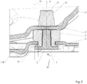
- connection components 4 As in the sectional view of Fig. 2 can be seen, the connection components 4 according to the prior art, an inner member 5 and an inner member 5 surrounding outer member 6.
- the outer element 6 is typically made of rubber.
- the inner element 5 has a greater rigidity than the outer element 6, which counteracts a setting of the outer element 6.
- the connecting element 4 has a longitudinal axis 24 which runs parallel to an axial direction 16. Transverse, preferably normal to the axial direction 16 is a transverse direction 28.
- the longitudinal axis 24 extends in the transverse direction 28 seen through the center of the connecting element 4. Seen from the longitudinal axis 24 in the transverse direction 28 to the outside, the outer element 6 is disposed behind the inner element 5 ,
- the inner member 5 may be sleeve-shaped, which allows the passage of a screw (not shown) for connecting the connecting member 4 to the housing 2.
- a steel spring pin 25 can be seen on which a spring (not shown) can be pressed, by means of which the drive unit (not shown) is mounted in the housing 2.
- the inner element 5 forms in the illustrated embodiment, a transport safety device 7 at its seen in the axial direction 16 free end by the inner member 5 expands there in the transverse direction 28.
- an extent 35 of the transport lock 7 in the transverse direction 28 is greater than an extension 34 of an opening 29 of the mounting plate 26, through which opening 29, the inner member 5 and the outer member 6 are passed in the axial direction 16. This in turn prevents the refrigerant compressor 1 in the axial direction 16 can be removed from the mounting plate 26.
- the outer element 6 forms over the transport lock 7 a damping layer 32.
- the cushioning layer 32 prevents hard metallic contact between the transportation lock 7 and the mounting plate 26, particularly if the refrigerant compressor 1 should have been improperly mounted and the refrigerant compressor 1 and mounting plate 26 should be biased against each other.
- FIG. 3 and Fig. 4 show a first embodiment of such a connecting component 4 according to the invention in a sectional view analogous to Fig. 2 , It shows Fig. 3 the connection component 4 according to the invention in an unloaded state without pressure component parallel to the axial direction 16th Fig. 4 In contrast, the connection component 4 according to the invention in a loaded state with at least one pressure component parallel to the axial direction 16, so that the housing 2 and the mounting plate 26 are pressed against each other parallel to the axial direction 16.
- the outer element 6 is preferably made of rubber or an elastomer with little or no compressibility manufactured.
- the inner element 5 is preferably made of metal, eg steel or stainless steel.
- the outer member 6 has an outer portion 9 and an inner portion 10, wherein the inner portion 10 is disposed closer to the inner member 5. Seen from the longitudinal axis 24 in the transverse direction 28 to the outside of the outer portion 9 is disposed behind the inner portion 10. In the axial direction 16, the outer portion 9 is bounded by a first end portion 11 and a second end portion 12. The inner portion 10 is bounded in the axial direction 16 by a first end portion 13 and a second end portion 14. The outer portion 9 and the inner portion 10 are connected to each other in the region of their second end portions 12, 14. Preferably, the outer element 6 is made in one piece.
- the sections 9, 10 have a symmetry about the longitudinal axis 24, whereby the outer portion 9 and the inner portion 10 normal to the longitudinal axis 24 each have at least partially an annular cross-section.
- the transverse direction 28 can therefore also be considered in the embodiment shown as a radial direction.
- other cross-sectional shapes are also possible, e.g. an elliptical or polygonal, in particular rectangular or square, cross-sectional shape.
- the outer element 6 is connected to the inner element 5.
- the outer member 6 is connected in the region of the second end portion 14 of the inner portion 10 with the inner member 5 via a press fit.
- another gap 33 connects to the press fit, which further gap 33 is thus in sections between the inner element 5 and the inner section 10 of the outer element 6 is trained.
- the further gap 33 serves to avoid a direct contact between the inner element 5, the inner portion 10 and the mounting plate 26. Respectively. allows the further gap 33 that the inner portion 10 can escape when the mounting plate 26 presses parallel to the transverse direction 28 against the inner portion 10 in the direction of inner element 5. Otherwise, a very strong unwanted transverse stiffness would result if the outer member 6 is made of rubber, since rubber is almost incompressible.
- the sections 9, 10 are supported on the housing 2 in the exemplary embodiment shown.
- the outer element 6 is supported in the region of the second end regions 12, 14 on the housing bottom 8.
- the outer portion 9 forms a functional portion 30, wherein the outer portion 9 is supported not only on the housing 2, but also at least in the loaded state of the connecting member 4 with its first end portion 11 on the mounting plate 26 of the refrigerator 3.
- the first end portion 13 of inner portion 10 projects through the opening 29 of the mounting plate 26 therethrough.
- the first end portion 13 of the inner portion 10 is thus movable relative to the mounting plate 26 in the axial direction 16 and vice versa.
- the outer portion 9 is designed so that there is a deformation of the outer portion 9 by buckling. That is, in the loaded state, the outer portion 9 or the functional portion 30 is a deformed portion 27 and has a kink 17, see. Fig. 4 , The inner portion 10, however, is not in the axial Direction 16 pressurized, since its first end portion 13 in the loaded state is simply moved relative to the mounting plate 16 parallel to the axial direction 16 and is. Accordingly, the inner portion 10 is not deformed in the loaded state.
- the gap 15 In the unloaded state ( Fig. 3 ) is between the outer portion 9 and the inner portion 10 sections a free space in the form of a gap 15 formed, which extends, at least in sections, annularly around the longitudinal axis 24 due to the existing symmetry in the illustrated embodiment.
- This gap 15 provides space for the outer section 9 or the functional section 30 in the loaded state (FIG. Fig. 4 ) in the direction of the inner portion 10 can buckle. Accordingly, the gap 15 is partially filled in the loaded state by the outer portion 9.
- the buckling can take place until the outer section 9 or the functional section 30 abuts a contact part 31.
- the contact part 31 is formed by the inner portion 10. This concern stabilizes the functional section 30 or the outer section 9 or the outer element 6.
- Outer element 6 or the outer portion 9 or the functional portion 30 are designed so that even relatively low pressures parallel to the axial direction 16 lead to a buckling of the outer portion 9 and the functional portion 30. This corresponds to a relatively unstable state or a very flat spring characteristic. But as soon as the outer portion 9 or the functional portion 30 rests against the inner portion 10 or the contact part 31, the outer portion 9 is stabilized. This is done with further pressure increase, whereby a substantially steeper characteristic is realized at these pressures and results in a total of a non-linear spring characteristic of the connecting member 4 according to the invention.
- How strong the buckling in dependence on the size of the pressure component is parallel to the axial direction 16 and how unstable the connecting member 4 is at relatively low pressures, can be determined inter alia by the choice of a wall thickness 18 of the outer portion 9.
- the wall thickness 18 can also be significantly greater than a wall thickness 19 of the inner portion 10.
- the wall thicknesses 18, 19 are preferably measured in the unloaded state, see. Fig. 3 ,
- FIG. 5 and Fig. 6 illustrated embodiment of the connecting member 4 according to the invention differs from the embodiment of Fig. 3 and Fig. 4 essentially in that the outer element 6 has only the functional section 30 instead of the two sections 9, 10.
- the functional portion 30 is supported, at least in the loaded state of the connecting component 4, both on the housing 2 or on the housing base 8 and on the device 3 or on the mounting plate 26.
- the contact part 31 is formed in this case by the inner element 5, which projects through the opening 29 of the mounting plate 26 in the axial direction 16 therethrough.
- the gap 15, which is free in the unloaded state of the connection component 4 and provides the necessary space for the deformation or for the buckling of the functional section 30 in the loaded state of the connection component 4, is correspondingly sectionwise between the inner element 5 and the outer element 6 or The functional section 30 is formed.
- the buckling can take place until the functional section 30 rests against the contact part 31 or against the inner element 5. This concern stabilizes the functional section 30 or the outer element 6.
- the opening 29 is preferably arranged in a step-stepped section of the mounting plate 26, in which stepped portion the outer element 6 is arranged. Due to the step shape is in the loaded state of Connecting member 4 of the functional portion 30 is supported at its the mounting plate 26 contacting end in the transverse direction 28 when the functional portion 30 buckles into the gap 15.
- the damping layer 32 on the transport lock 7 is in Fig. 5 and Fig. 6 not shown separately. However, it may of course be provided such, for example by a coating of the transport lock 7 with rubber or otherwise an elastic or damping material.
Landscapes
- Engineering & Computer Science (AREA)
- Mechanical Engineering (AREA)
- General Engineering & Computer Science (AREA)
- Chemical & Material Sciences (AREA)
- Combustion & Propulsion (AREA)
- Physics & Mathematics (AREA)
- Thermal Sciences (AREA)
- Compressor (AREA)
Claims (15)
- Composant de raccordement (4) d'un compresseur de réfrigérant (1) pour le raccordement d'un carter (2) du compresseur de réfrigérant (1) à un dispositif en liaison fonctionnelle avec le compresseur de réfrigérant (1), de préférence à une plaque de montage (26) d'un appareil de réfrigération (3), le composant de raccordement (4) comprenant un élément intérieur (5) et un élément extérieur (6) entourant l'élément intérieur (5), l'élément intérieur (5) présentant une rigidité plus élevée que l'élément extérieur (6) et l'élément extérieur (6) présentant une partie fonctionnelle (30) qui est conçue de telle sorte que, à un état chargé du composant de raccordement (4), elle prend appui à la fois sur le carter (2) et sur le dispositif (3), de préférence la plaque de montage (26), un mouvement relatif du carter (2) et du dispositif l'un par rapport à l'autre et parallèle à une direction axiale (16) ayant lieu à l'état chargé et une charge de pression régnant parallèlement à la direction axiale (16), un espace libre (15) étant prévu, qui fait suite à la partie fonctionnelle (30) de l'élément extérieur (6) vu dans une direction transversale (28), l'élément intérieur (5) et l'élément extérieur (6) étant disposés l'un derrière l'autre vus parallèlement à la direction transversale (28) et, à l'état chargé du composant de raccordement (4), la partie fonctionnelle (30) étant déformée de telle sorte qu'elle fait saillie au moins sur certaines parties dans l'espace libre (15), l'élément extérieur (6) présentant une partie intérieure (10) disposée plus près de l'élément intérieur (5) et une partie extérieure (9), la partie fonctionnelle (30) étant formée par l'une des deux parties (9, 10), caractérisé en ce que, à l'état chargé du composant de raccordement (4), des deux parties (9, 10) seule la partie fonctionnelle (30) prend appui à la fois sur le carter (2) et sur le dispositif (3), de préférence la plaque de montage (26), et que, à l'état chargé du composant de raccordement (4), la partie fonctionnelle déformée (30) s'applique au moins partiellement contre une partie d'appui (31) du composant de raccordement (4), laquelle partie d'appui (31) fait suite à l'espace libre (15) vue dans la direction transversale (28).
- Composant de raccordement (4) selon la revendication 1, caractérisé en ce que la partie fonctionnelle déformée (30) comprend une partie (27) avec un coude (17), la partie (27) de la partie fonctionnelle (30) présentant le coude (17) faisant saillie au moins partiellement dans l'espace libre (15).
- Composant de raccordement (4) selon l'une des revendications 1 à 2, caractérisé en ce que la partie d'appui (31) du composant de raccordement (4) est formée par l'élément intérieur (5).
- Composant de raccordement (4) selon l'une des revendications 1 à 3, caractérisé en ce que l'espace libre (15) est formé au moins sur certaines parties entre la partie intérieure (10) et la partie extérieure (9).
- Composant de raccordement (4) selon la revendication 4, caractérisé en ce que la partie d'appui (31) est formée par l'autre des deux parties (10, 9).
- Composant de raccordement (4) selon l'une des revendications 1 à 5, caractérisé en ce que, vue dans la direction transversale (28), la partie fonctionnelle (30) présente une épaisseur de paroi (18) plus grande que l'autre des deux parties (10, 9) au moins sur certaines parties.
- Composant de raccordement (4) selon l'une des revendications 1 à 6, caractérisé en ce que la partie fonctionnelle (30), à l'état non chargé du composant de raccordement (4), présente, vue dans la direction axiale (16), une longueur (20) plus petite que l'autre des deux sections (10, 9), la direction transversale (28) s'étendant transversalement à la direction axiale (16).
- Composant de raccordement (4) selon l'une des revendications 1 à 7, caractérisé en ce que la partie fonctionnelle (30) présente, vue dans la direction axiale (16), une longueur (20) plus grande à l'état non chargé du composant de raccordement (4) qu'à l'état chargé du composant de raccordement (4), la direction transversale (28) s'étendant transversalement à la direction axiale (16).
- Composant de raccordement (4) selon l'une des revendications 1 à 8, caractérisé en ce que la partie fonctionnelle (30) est formée par la partie extérieure (9).
- Composant de raccordement (4) selon l'une des revendications 1 à 9, caractérisé en ce que les deux parties (9, 10) sont reliées l'une à l'autre, de préférence au niveau d'une zone d'extrémité (11, 13) de la partie respective (9, 10).
- Composant de raccordement (4) selon l'une des revendications 1 à 10, caractérisé en ce que l'élément extérieur (6) est réalisé d'une seule pièce.
- Composant de raccordement (4) selon l'une des revendications 1 à 11, caractérisé en ce que l'élément extérieur (6) est réalisé en caoutchouc ou en élastomère.
- Compresseur de réfrigérant (1) comprenant un carter hermétiquement fermé (2) ainsi qu'une unité d'entraînement avec une unité à piston et cylindre disposée à l'intérieur du carter (2) pour la compression cyclique d'un réfrigérant et un moteur électrique pour l'entraînement de l'unité à piston et cylindre, le compresseur de réfrigérant (1) comprenant en outre au moins un composant de raccordement (4) selon l'une des revendications 1 à 12 pour raccorder le carter (2) à un dispositif en liaison fonctionnelle avec le compresseur de réfrigérant (1), de préférence à une plaque de montage (26) d'un appareil de réfrigération (3).
- Système comprenant un compresseur de réfrigérant (1) selon la revendication 13 ainsi qu'un dispositif en liaison fonctionnelle avec le compresseur de réfrigérant (1), de préférence un appareil de réfrigération (3), le dispositif comprenant une plaque de montage (26) à laquelle le carter (2) du compresseur de réfrigérant (1) est raccordé au moyen dudit au moins un composant de raccordement (4), la partie fonctionnelle (30) prenant appui à la fois sur le carter (2) et sur la plaque de montage (26) à l'état chargé du composant de raccordement (4).
- Système selon la revendication 14, caractérisé en ce qu'une ouverture (29) et/ou un évidement et/ou un gradin est prévu(e) dans la plaque de montage (26), dans lequel ou laquelle la partie d'appui (31) fait saillie à l'état chargé du composant de raccordement (4).
Applications Claiming Priority (2)
| Application Number | Priority Date | Filing Date | Title |
|---|---|---|---|
| ATGM50130/2015U AT14820U1 (de) | 2015-06-30 | 2015-06-30 | Verbindungsbauteil eines Kältemittel Verdichters |
| PCT/EP2016/065333 WO2017001574A1 (fr) | 2015-06-30 | 2016-06-30 | Composant de liaison d'un compresseur frigorifique |
Publications (2)
| Publication Number | Publication Date |
|---|---|
| EP3317599A1 EP3317599A1 (fr) | 2018-05-09 |
| EP3317599B1 true EP3317599B1 (fr) | 2018-10-31 |
Family
ID=56320691
Family Applications (1)
| Application Number | Title | Priority Date | Filing Date |
|---|---|---|---|
| EP16735617.9A Active EP3317599B1 (fr) | 2015-06-30 | 2016-06-30 | Élément de raccordement d'un compresseur de réfrigérant |
Country Status (5)
| Country | Link |
|---|---|
| US (1) | US10865781B2 (fr) |
| EP (1) | EP3317599B1 (fr) |
| CN (1) | CN108139139B (fr) |
| AT (1) | AT14820U1 (fr) |
| WO (1) | WO2017001574A1 (fr) |
Families Citing this family (4)
| Publication number | Priority date | Publication date | Assignee | Title |
|---|---|---|---|---|
| AU2018451774A1 (en) * | 2018-12-06 | 2021-05-20 | Electrolux Appliances Aktiebolag | Refrigerator with a compressor |
| CN113669234B (zh) * | 2020-05-15 | 2025-11-21 | 安徽美芝制冷设备有限公司 | 支撑组件、压缩机和制冷设备 |
| CN113606112A (zh) * | 2020-12-29 | 2021-11-05 | 广州赛佛科技有限公司 | 一种加压减压方法及其装置 |
| JP7589612B2 (ja) * | 2021-03-23 | 2024-11-26 | 株式会社豊田自動織機 | 車載用電動流体機械 |
Family Cites Families (19)
| Publication number | Priority date | Publication date | Assignee | Title |
|---|---|---|---|---|
| US2551514A (en) * | 1948-01-06 | 1951-05-01 | Westinghouse Electric Corp | Mounting arrangement of refrigeration unit |
| JPS58195138U (ja) | 1982-06-21 | 1983-12-26 | ダイキン工業株式会社 | 圧縮機の支持具 |
| JPS59188336U (ja) | 1983-06-02 | 1984-12-13 | 三菱電機株式会社 | 振動発生機器用の防振支持装置 |
| JPS6159039A (ja) * | 1984-08-29 | 1986-03-26 | Natl Tire Kk | 圧縮機等の防振支持装置 |
| JPS6263439U (fr) | 1985-10-11 | 1987-04-20 | ||
| JPS6488042A (en) | 1987-09-28 | 1989-04-03 | Matsushita Electric Industrial Co Ltd | Compressor vibration isolating device of air conditioner |
| US5277554A (en) * | 1992-11-13 | 1994-01-11 | Copeland Corporation | Tandem compressor mounting system |
| JPH1030562A (ja) * | 1996-07-15 | 1998-02-03 | Matsushita Refrig Co Ltd | 冷蔵庫 |
| KR100546677B1 (ko) * | 2003-11-13 | 2006-01-26 | 엘지전자 주식회사 | 압축기용 방진고무 |
| JP4715673B2 (ja) | 2006-08-04 | 2011-07-06 | 株式会社デンソー | 車両用防振装置 |
| JP2009185775A (ja) | 2008-02-08 | 2009-08-20 | Toshiba Corp | 冷却ユニット |
| KR101392541B1 (ko) | 2008-03-13 | 2014-05-07 | 엘지전자 주식회사 | 압축기 고정구조 및 이를 포함하는 공기조화기의 실외기 |
| RU2405246C2 (ru) * | 2008-04-15 | 2010-11-27 | Институт проблем информатики Российской академии наук (ИПИ РАН) | Самосинхронный триггер с однофазным информационным входом |
| JP5365994B2 (ja) | 2009-01-16 | 2013-12-11 | 日立工機株式会社 | 空気圧縮機 |
| KR20110043252A (ko) * | 2009-10-21 | 2011-04-27 | 엘지전자 주식회사 | 공기조화기용 압축기의 방진장치 |
| JP2012026623A (ja) * | 2010-07-22 | 2012-02-09 | Hitachi Appliances Inc | 冷蔵庫 |
| JP5682240B2 (ja) * | 2010-11-08 | 2015-03-11 | パナソニックIpマネジメント株式会社 | 冷蔵庫 |
| WO2012153518A1 (fr) * | 2011-05-09 | 2012-11-15 | パナソニック株式会社 | Réfrigérateur |
| JP5208288B1 (ja) * | 2012-01-25 | 2013-06-12 | ヤマウチ株式会社 | コンプレッサ用防振ゴムおよびそれを用いたコンプレッサ |
-
2015
- 2015-06-30 AT ATGM50130/2015U patent/AT14820U1/de unknown
-
2016
- 2016-06-30 US US15/741,112 patent/US10865781B2/en active Active
- 2016-06-30 WO PCT/EP2016/065333 patent/WO2017001574A1/fr not_active Ceased
- 2016-06-30 EP EP16735617.9A patent/EP3317599B1/fr active Active
- 2016-06-30 CN CN201680049145.8A patent/CN108139139B/zh active Active
Non-Patent Citations (1)
| Title |
|---|
| None * |
Also Published As
| Publication number | Publication date |
|---|---|
| WO2017001574A1 (fr) | 2017-01-05 |
| EP3317599A1 (fr) | 2018-05-09 |
| AT14820U1 (de) | 2016-07-15 |
| CN108139139A (zh) | 2018-06-08 |
| CN108139139B (zh) | 2021-03-30 |
| US10865781B2 (en) | 2020-12-15 |
| US20200032782A1 (en) | 2020-01-30 |
Similar Documents
| Publication | Publication Date | Title |
|---|---|---|
| EP2683961B1 (fr) | Coussinet pouvant être précontraint par refoulement de matériau et palier équipé de ce coussinet | |
| EP3317599B1 (fr) | Élément de raccordement d'un compresseur de réfrigérant | |
| DE112016002359B4 (de) | Pulsationsdämpfer für eine kraftstoffpumpe | |
| EP2561245B1 (fr) | Capuchon de butée | |
| EP2946123B1 (fr) | Joint sphérique | |
| DE29609769U1 (de) | Dichtungsanordnung zwischen einer Flanschverbindung | |
| EP3303840B1 (fr) | Compresseur à réfrigérant | |
| DE102013208270A1 (de) | Feder und System | |
| WO2019029865A1 (fr) | Dispositif d'application d'une crémaillère | |
| EP2459905B1 (fr) | Joint d'étanchéité et agencement doté d'un joint d'étanchéité | |
| EP3277977B1 (fr) | Amortisseur axial | |
| DE102008029642A1 (de) | Tellerfederanordnung | |
| DE10344102B3 (de) | Federträger mit einer Zusatzfeder | |
| EP3313712A1 (fr) | Articulation à rotule axiale | |
| DE202007012345U1 (de) | Metallbalg | |
| WO2014009428A1 (fr) | Dispositif pour presser une crémaillère contre un pignon | |
| EP2906850B1 (fr) | Palier à coussinets | |
| DE2121067A1 (de) | Elastisches Lager, insbesondere für die Motoraufhängung in Kraftfahrzeugen | |
| EP3140550B1 (fr) | Dispositif d'étanchéité pour une pompe haute pression et pompe haute pression dotée d'un tel dispositif d'étanchéité | |
| DE202014102513U1 (de) | Spanneinheit | |
| EP3855046B1 (fr) | Entraînement à broche | |
| EP3414468B1 (fr) | Dispositif de suspension et de fixation pour fixation d'un element de machine ainsi qu'utilisation | |
| EP2604884B1 (fr) | Support hydraulique et son utilisation | |
| WO2015059198A1 (fr) | Bague de palier | |
| EP1571366B1 (fr) | Support élastique |
Legal Events
| Date | Code | Title | Description |
|---|---|---|---|
| STAA | Information on the status of an ep patent application or granted ep patent |
Free format text: STATUS: THE INTERNATIONAL PUBLICATION HAS BEEN MADE |
|
| PUAI | Public reference made under article 153(3) epc to a published international application that has entered the european phase |
Free format text: ORIGINAL CODE: 0009012 |
|
| STAA | Information on the status of an ep patent application or granted ep patent |
Free format text: STATUS: REQUEST FOR EXAMINATION WAS MADE |
|
| 17P | Request for examination filed |
Effective date: 20180125 |
|
| AK | Designated contracting states |
Kind code of ref document: A1 Designated state(s): AL AT BE BG CH CY CZ DE DK EE ES FI FR GB GR HR HU IE IS IT LI LT LU LV MC MK MT NL NO PL PT RO RS SE SI SK SM TR |
|
| AX | Request for extension of the european patent |
Extension state: BA ME |
|
| GRAP | Despatch of communication of intention to grant a patent |
Free format text: ORIGINAL CODE: EPIDOSNIGR1 |
|
| STAA | Information on the status of an ep patent application or granted ep patent |
Free format text: STATUS: GRANT OF PATENT IS INTENDED |
|
| DAX | Request for extension of the european patent (deleted) | ||
| INTG | Intention to grant announced |
Effective date: 20180514 |
|
| GRAS | Grant fee paid |
Free format text: ORIGINAL CODE: EPIDOSNIGR3 |
|
| GRAA | (expected) grant |
Free format text: ORIGINAL CODE: 0009210 |
|
| STAA | Information on the status of an ep patent application or granted ep patent |
Free format text: STATUS: THE PATENT HAS BEEN GRANTED |
|
| DAV | Request for validation of the european patent (deleted) | ||
| AK | Designated contracting states |
Kind code of ref document: B1 Designated state(s): AL AT BE BG CH CY CZ DE DK EE ES FI FR GB GR HR HU IE IS IT LI LT LU LV MC MK MT NL NO PL PT RO RS SE SI SK SM TR |
|
| REG | Reference to a national code |
Ref country code: CH Ref legal event code: EP Ref country code: GB Ref legal event code: FG4D Free format text: NOT ENGLISH |
|
| REG | Reference to a national code |
Ref country code: AT Ref legal event code: REF Ref document number: 1059887 Country of ref document: AT Kind code of ref document: T Effective date: 20181115 |
|
| REG | Reference to a national code |
Ref country code: DE Ref legal event code: R096 Ref document number: 502016002391 Country of ref document: DE |
|
| REG | Reference to a national code |
Ref country code: IE Ref legal event code: FG4D Free format text: LANGUAGE OF EP DOCUMENT: GERMAN |
|
| REG | Reference to a national code |
Ref country code: NL Ref legal event code: MP Effective date: 20181031 |
|
| REG | Reference to a national code |
Ref country code: LT Ref legal event code: MG4D |
|
| PG25 | Lapsed in a contracting state [announced via postgrant information from national office to epo] |
Ref country code: FI Free format text: LAPSE BECAUSE OF FAILURE TO SUBMIT A TRANSLATION OF THE DESCRIPTION OR TO PAY THE FEE WITHIN THE PRESCRIBED TIME-LIMIT Effective date: 20181031 Ref country code: BG Free format text: LAPSE BECAUSE OF FAILURE TO SUBMIT A TRANSLATION OF THE DESCRIPTION OR TO PAY THE FEE WITHIN THE PRESCRIBED TIME-LIMIT Effective date: 20190131 Ref country code: LT Free format text: LAPSE BECAUSE OF FAILURE TO SUBMIT A TRANSLATION OF THE DESCRIPTION OR TO PAY THE FEE WITHIN THE PRESCRIBED TIME-LIMIT Effective date: 20181031 Ref country code: HR Free format text: LAPSE BECAUSE OF FAILURE TO SUBMIT A TRANSLATION OF THE DESCRIPTION OR TO PAY THE FEE WITHIN THE PRESCRIBED TIME-LIMIT Effective date: 20181031 Ref country code: PL Free format text: LAPSE BECAUSE OF FAILURE TO SUBMIT A TRANSLATION OF THE DESCRIPTION OR TO PAY THE FEE WITHIN THE PRESCRIBED TIME-LIMIT Effective date: 20181031 Ref country code: LV Free format text: LAPSE BECAUSE OF FAILURE TO SUBMIT A TRANSLATION OF THE DESCRIPTION OR TO PAY THE FEE WITHIN THE PRESCRIBED TIME-LIMIT Effective date: 20181031 Ref country code: ES Free format text: LAPSE BECAUSE OF FAILURE TO SUBMIT A TRANSLATION OF THE DESCRIPTION OR TO PAY THE FEE WITHIN THE PRESCRIBED TIME-LIMIT Effective date: 20181031 Ref country code: IS Free format text: LAPSE BECAUSE OF FAILURE TO SUBMIT A TRANSLATION OF THE DESCRIPTION OR TO PAY THE FEE WITHIN THE PRESCRIBED TIME-LIMIT Effective date: 20190228 Ref country code: NO Free format text: LAPSE BECAUSE OF FAILURE TO SUBMIT A TRANSLATION OF THE DESCRIPTION OR TO PAY THE FEE WITHIN THE PRESCRIBED TIME-LIMIT Effective date: 20190131 |
|
| PG25 | Lapsed in a contracting state [announced via postgrant information from national office to epo] |
Ref country code: PT Free format text: LAPSE BECAUSE OF FAILURE TO SUBMIT A TRANSLATION OF THE DESCRIPTION OR TO PAY THE FEE WITHIN THE PRESCRIBED TIME-LIMIT Effective date: 20190301 Ref country code: RS Free format text: LAPSE BECAUSE OF FAILURE TO SUBMIT A TRANSLATION OF THE DESCRIPTION OR TO PAY THE FEE WITHIN THE PRESCRIBED TIME-LIMIT Effective date: 20181031 Ref country code: GR Free format text: LAPSE BECAUSE OF FAILURE TO SUBMIT A TRANSLATION OF THE DESCRIPTION OR TO PAY THE FEE WITHIN THE PRESCRIBED TIME-LIMIT Effective date: 20190201 Ref country code: SE Free format text: LAPSE BECAUSE OF FAILURE TO SUBMIT A TRANSLATION OF THE DESCRIPTION OR TO PAY THE FEE WITHIN THE PRESCRIBED TIME-LIMIT Effective date: 20181031 Ref country code: NL Free format text: LAPSE BECAUSE OF FAILURE TO SUBMIT A TRANSLATION OF THE DESCRIPTION OR TO PAY THE FEE WITHIN THE PRESCRIBED TIME-LIMIT Effective date: 20181031 Ref country code: AL Free format text: LAPSE BECAUSE OF FAILURE TO SUBMIT A TRANSLATION OF THE DESCRIPTION OR TO PAY THE FEE WITHIN THE PRESCRIBED TIME-LIMIT Effective date: 20181031 |
|
| PG25 | Lapsed in a contracting state [announced via postgrant information from national office to epo] |
Ref country code: CZ Free format text: LAPSE BECAUSE OF FAILURE TO SUBMIT A TRANSLATION OF THE DESCRIPTION OR TO PAY THE FEE WITHIN THE PRESCRIBED TIME-LIMIT Effective date: 20181031 Ref country code: DK Free format text: LAPSE BECAUSE OF FAILURE TO SUBMIT A TRANSLATION OF THE DESCRIPTION OR TO PAY THE FEE WITHIN THE PRESCRIBED TIME-LIMIT Effective date: 20181031 |
|
| REG | Reference to a national code |
Ref country code: DE Ref legal event code: R097 Ref document number: 502016002391 Country of ref document: DE |
|
| PG25 | Lapsed in a contracting state [announced via postgrant information from national office to epo] |
Ref country code: SK Free format text: LAPSE BECAUSE OF FAILURE TO SUBMIT A TRANSLATION OF THE DESCRIPTION OR TO PAY THE FEE WITHIN THE PRESCRIBED TIME-LIMIT Effective date: 20181031 Ref country code: RO Free format text: LAPSE BECAUSE OF FAILURE TO SUBMIT A TRANSLATION OF THE DESCRIPTION OR TO PAY THE FEE WITHIN THE PRESCRIBED TIME-LIMIT Effective date: 20181031 Ref country code: SM Free format text: LAPSE BECAUSE OF FAILURE TO SUBMIT A TRANSLATION OF THE DESCRIPTION OR TO PAY THE FEE WITHIN THE PRESCRIBED TIME-LIMIT Effective date: 20181031 Ref country code: EE Free format text: LAPSE BECAUSE OF FAILURE TO SUBMIT A TRANSLATION OF THE DESCRIPTION OR TO PAY THE FEE WITHIN THE PRESCRIBED TIME-LIMIT Effective date: 20181031 |
|
| PLBE | No opposition filed within time limit |
Free format text: ORIGINAL CODE: 0009261 |
|
| STAA | Information on the status of an ep patent application or granted ep patent |
Free format text: STATUS: NO OPPOSITION FILED WITHIN TIME LIMIT |
|
| 26N | No opposition filed |
Effective date: 20190801 |
|
| PG25 | Lapsed in a contracting state [announced via postgrant information from national office to epo] |
Ref country code: MC Free format text: LAPSE BECAUSE OF FAILURE TO SUBMIT A TRANSLATION OF THE DESCRIPTION OR TO PAY THE FEE WITHIN THE PRESCRIBED TIME-LIMIT Effective date: 20181031 |
|
| REG | Reference to a national code |
Ref country code: CH Ref legal event code: PL |
|
| REG | Reference to a national code |
Ref country code: BE Ref legal event code: MM Effective date: 20190630 |
|
| PG25 | Lapsed in a contracting state [announced via postgrant information from national office to epo] |
Ref country code: TR Free format text: LAPSE BECAUSE OF FAILURE TO SUBMIT A TRANSLATION OF THE DESCRIPTION OR TO PAY THE FEE WITHIN THE PRESCRIBED TIME-LIMIT Effective date: 20181031 |
|
| PG25 | Lapsed in a contracting state [announced via postgrant information from national office to epo] |
Ref country code: IE Free format text: LAPSE BECAUSE OF NON-PAYMENT OF DUE FEES Effective date: 20190630 |
|
| PG25 | Lapsed in a contracting state [announced via postgrant information from national office to epo] |
Ref country code: BE Free format text: LAPSE BECAUSE OF NON-PAYMENT OF DUE FEES Effective date: 20190630 Ref country code: LU Free format text: LAPSE BECAUSE OF NON-PAYMENT OF DUE FEES Effective date: 20190630 Ref country code: LI Free format text: LAPSE BECAUSE OF NON-PAYMENT OF DUE FEES Effective date: 20190630 Ref country code: CH Free format text: LAPSE BECAUSE OF NON-PAYMENT OF DUE FEES Effective date: 20190630 |
|
| PG25 | Lapsed in a contracting state [announced via postgrant information from national office to epo] |
Ref country code: FR Free format text: LAPSE BECAUSE OF NON-PAYMENT OF DUE FEES Effective date: 20190630 |
|
| REG | Reference to a national code |
Ref country code: DE Ref legal event code: R082 Ref document number: 502016002391 Country of ref document: DE Representative=s name: KUHNEN & WACKER PATENT- UND RECHTSANWALTSBUERO, DE Ref country code: DE Ref legal event code: R081 Ref document number: 502016002391 Country of ref document: DE Owner name: SECOP GMBH, DE Free format text: FORMER OWNER: NIDEC GLOBAL APPLIANCE GERMANY GMBH, 24939 FLENSBURG, DE |
|
| GBPC | Gb: european patent ceased through non-payment of renewal fee |
Effective date: 20200630 |
|
| PG25 | Lapsed in a contracting state [announced via postgrant information from national office to epo] |
Ref country code: GB Free format text: LAPSE BECAUSE OF NON-PAYMENT OF DUE FEES Effective date: 20200630 |
|
| PG25 | Lapsed in a contracting state [announced via postgrant information from national office to epo] |
Ref country code: CY Free format text: LAPSE BECAUSE OF FAILURE TO SUBMIT A TRANSLATION OF THE DESCRIPTION OR TO PAY THE FEE WITHIN THE PRESCRIBED TIME-LIMIT Effective date: 20181031 |
|
| PG25 | Lapsed in a contracting state [announced via postgrant information from national office to epo] |
Ref country code: MT Free format text: LAPSE BECAUSE OF FAILURE TO SUBMIT A TRANSLATION OF THE DESCRIPTION OR TO PAY THE FEE WITHIN THE PRESCRIBED TIME-LIMIT Effective date: 20181031 Ref country code: HU Free format text: LAPSE BECAUSE OF FAILURE TO SUBMIT A TRANSLATION OF THE DESCRIPTION OR TO PAY THE FEE WITHIN THE PRESCRIBED TIME-LIMIT; INVALID AB INITIO Effective date: 20160630 |
|
| PG25 | Lapsed in a contracting state [announced via postgrant information from national office to epo] |
Ref country code: SI Free format text: LAPSE BECAUSE OF FAILURE TO SUBMIT A TRANSLATION OF THE DESCRIPTION OR TO PAY THE FEE WITHIN THE PRESCRIBED TIME-LIMIT Effective date: 20181031 |
|
| PG25 | Lapsed in a contracting state [announced via postgrant information from national office to epo] |
Ref country code: MK Free format text: LAPSE BECAUSE OF FAILURE TO SUBMIT A TRANSLATION OF THE DESCRIPTION OR TO PAY THE FEE WITHIN THE PRESCRIBED TIME-LIMIT Effective date: 20181031 |
|
| REG | Reference to a national code |
Ref country code: AT Ref legal event code: MM01 Ref document number: 1059887 Country of ref document: AT Kind code of ref document: T Effective date: 20210630 |
|
| PG25 | Lapsed in a contracting state [announced via postgrant information from national office to epo] |
Ref country code: AT Free format text: LAPSE BECAUSE OF NON-PAYMENT OF DUE FEES Effective date: 20210630 |
|
| P01 | Opt-out of the competence of the unified patent court (upc) registered |
Effective date: 20230517 |
|
| PGFP | Annual fee paid to national office [announced via postgrant information from national office to epo] |
Ref country code: DE Payment date: 20250626 Year of fee payment: 10 |
|
| PGFP | Annual fee paid to national office [announced via postgrant information from national office to epo] |
Ref country code: IT Payment date: 20250623 Year of fee payment: 10 |