EP3318330A1 - Zerkleinerungsmaschine - Google Patents
Zerkleinerungsmaschine Download PDFInfo
- Publication number
- EP3318330A1 EP3318330A1 EP17199934.5A EP17199934A EP3318330A1 EP 3318330 A1 EP3318330 A1 EP 3318330A1 EP 17199934 A EP17199934 A EP 17199934A EP 3318330 A1 EP3318330 A1 EP 3318330A1
- Authority
- EP
- European Patent Office
- Prior art keywords
- crushing
- tools
- rotor
- crushed
- crushing rotor
- Prior art date
- Legal status (The legal status is an assumption and is not a legal conclusion. Google has not performed a legal analysis and makes no representation as to the accuracy of the status listed.)
- Withdrawn
Links
Images


Classifications
-
- B—PERFORMING OPERATIONS; TRANSPORTING
- B02—CRUSHING, PULVERISING, OR DISINTEGRATING; PREPARATORY TREATMENT OF GRAIN FOR MILLING
- B02C—CRUSHING, PULVERISING, OR DISINTEGRATING IN GENERAL; MILLING GRAIN
- B02C13/00—Disintegrating by mills having rotary beater elements ; Hammer mills
- B02C13/14—Disintegrating by mills having rotary beater elements ; Hammer mills with vertical rotor shaft, e.g. combined with sifting devices
- B02C13/18—Disintegrating by mills having rotary beater elements ; Hammer mills with vertical rotor shaft, e.g. combined with sifting devices with beaters rigidly connected to the rotor
- B02C13/1807—Disintegrating by mills having rotary beater elements ; Hammer mills with vertical rotor shaft, e.g. combined with sifting devices with beaters rigidly connected to the rotor the material to be crushed being thrown against an anvil or impact plate
- B02C13/1814—Disintegrating by mills having rotary beater elements ; Hammer mills with vertical rotor shaft, e.g. combined with sifting devices with beaters rigidly connected to the rotor the material to be crushed being thrown against an anvil or impact plate by means of beater or impeller elements fixed on top of a disc type rotor
- B02C13/1821—Disintegrating by mills having rotary beater elements ; Hammer mills with vertical rotor shaft, e.g. combined with sifting devices with beaters rigidly connected to the rotor the material to be crushed being thrown against an anvil or impact plate by means of beater or impeller elements fixed on top of a disc type rotor the beater or impeller elements being rotatably fixed around their own axis
-
- B—PERFORMING OPERATIONS; TRANSPORTING
- B02—CRUSHING, PULVERISING, OR DISINTEGRATING; PREPARATORY TREATMENT OF GRAIN FOR MILLING
- B02C—CRUSHING, PULVERISING, OR DISINTEGRATING IN GENERAL; MILLING GRAIN
- B02C13/00—Disintegrating by mills having rotary beater elements ; Hammer mills
- B02C13/14—Disintegrating by mills having rotary beater elements ; Hammer mills with vertical rotor shaft, e.g. combined with sifting devices
- B02C13/16—Disintegrating by mills having rotary beater elements ; Hammer mills with vertical rotor shaft, e.g. combined with sifting devices with beaters hinged to the rotor
-
- B—PERFORMING OPERATIONS; TRANSPORTING
- B02—CRUSHING, PULVERISING, OR DISINTEGRATING; PREPARATORY TREATMENT OF GRAIN FOR MILLING
- B02C—CRUSHING, PULVERISING, OR DISINTEGRATING IN GENERAL; MILLING GRAIN
- B02C13/00—Disintegrating by mills having rotary beater elements ; Hammer mills
- B02C13/26—Details
- B02C13/282—Shape or inner surface of mill-housings
Definitions
- the present invention concerns a crushing apparatus for crushing and reducing parts in materials of various kinds, in particular waste materials. More in detail, the apparatus according to the invention is capable of crushing objects, or parts thereof, reducing them into sub-parts of the desired size.
- crushing apparatus also called “crushing mills”
- crushing mills to treat a variety of waste in metal, plastic materials, fibrous and other materials, even organic, such as plants or the like.
- Apparatus of this type are mainly used to treat urban waste, industrial waste, construction waste, or to dispose of motor vehicles, and parts thereof, in order to separate materials of different kinds and, where possible, recycle them.
- These apparatus generally comprise a crushing rotor consisting of a cylinder, or drum, fixed on the periphery of which is a plurality of protruding elements, also called “hammers”, for crushing the material.
- a crushing rotor consisting of a cylinder, or drum, fixed on the periphery of which is a plurality of protruding elements, also called “hammers”, for crushing the material.
- the crushing rotor is positioned inside a crushing chamber, delimited peripherally by wall elements, and provided with an opening, generally upper, through which it receives the material to be crushed.
- the hammers of the crushing rotor By rotating, the hammers of the crushing rotor continuously impact the parts of material to be crushed fed to the inlet, progressively reducing their size, until they can pass between the crushing rotor and the walls, toward an outlet, in the lower part of the crushing chamber.
- a grid element is positioned at the outlet, through which the crushed material of suitable size, i.e., sufficiently small to pass through the mesh of the grid element, can exit from the crushing chamber to be collected for the intended purposes.
- Apparatus thus configured are known, for example, from US 5911372 A , US 7222805 B1 and WO 01/83111 A1 .
- the size or "granulometry" of the crushed material is substantially determined by the size of the openings in the grid element. If, with the same apparatus, a product crushed into parts of smaller or larger size is to be obtained, the grid element must be replaced with one having "mesh" of a suitable size. However, this operation is somewhat lengthy and difficult as it requires the disassembly and removal of numerous parts of the machinery, including the crushing rotor, often bulky and very heavy.
- an apparatus thus configured must be sized both from a structural and from an operating point of view (motors, systems, etc.) to be able to withstand these forces. For this reason, known apparatus are generally very large and powerful and, consequently, also costly.
- the object of the present invention is to propose a crushing apparatus that solves the problems of the prior art described above.
- the object of the present invention is to propose a versatile and inexpensive crushing apparatus.
- the object of the invention is to propose a crushing apparatus capable of treating materials of different kinds and provide a product crushed into parts of the desired size.
- Another object of the present invention is to provide a crushing apparatus that, with the same dimensions and power, can treat tougher materials and parts of larger sizes with respect to known systems.
- a further object of the present invention is to produce a crushing apparatus of simple design, which allows maintenance or reconfiguration operations to be carried out practically and rapidly.
- a crushing apparatus in which the crushing rotor is arranged vertically in the crushing chamber.
- This arrangement allows the creation of a plurality of crushing stages, or surfaces, aligned consecutively along the axis of the rotor.
- Each crushing stage is equipped with one or, preferably, with a plurality of tools set in rotation at least about the axis of the crushing rotor.
- the crushing chamber is delimited by a lateral wall that at least partially, and preferably completely, surrounds the crushing rotor.
- the material to be crushed tends to pass into the space between the lateral wall and the crushing rotor where, compressed between the tools and the inner surface of said lateral wall, it is crushed into parts of smaller size.
- each stage can be configured to reduce the material to a smaller size with respect to the stage that precedes it.
- the apparatus is able to produce crushed material of different sizes.
- the crushing rotor requires less power with respect to known apparatus. This enables the dimensions and, therefore, also the cost of the apparatus, to be limited.
- crushing refers generically to the reduction of parts of a material into sub-parts of smaller sizes. This reduction, as a function of the kind of material, can thus take place through actual crushing but also through deformation or tearing of the parts of the aforesaid material.
- the invention concerns a crushing apparatus comprising:
- the vertical arrangement of the rotor allows the crushing apparatus to operate in a substantially different way with respect to many known apparatus and with various advantages.
- the material to be crushed proceeds from the inlet toward the outlet mainly as a result of gravity. More in detail, the material to be crushed is conveyed between an inner surface of the crushing chamber and the crushing rotor; this latter is equipped with tools, arranged at the lateral perimeter, configured to treat the material to be crushed pressing it against the inner surface so that it is crushed and reduced in size.
- This crushing is therefore mainly implemented through breaking, deformation or tearing actions of the parts of the material, due to compression of the material between the tools and the inner surface and simultaneous rotation of the crushing rotor.
- This space can have a continuous section, for example it can be a circular ring that surrounds the crushing rotor, or, preferably, it can be obtained in one or more specific areas of the crushing chamber, where the inner surface is distanced from the crushing rotor.
- the crushing rotor can comprise several sections, each of which can be equipped with at least one tool. Said sections, preferably aligned and superimposed along the rotation axis, define respective crushing stages.
- each stage can be configured to carry out a progressive reduction of the size of the crushed material with respect to the preceding stage.
- the first crushing stage closest to the inlet, crushes the parts of material loaded into the apparatus until reducing them to a size that allows them to drop toward the next stage. The same thing occurs in the next stage and so forth until the material reaches the outlet of the crushing chamber.
- the inner surface of the lateral wall can have at least one segment converging toward said outlet of the crushed material.
- said converging segment is in the lower portion of the crushing chamber.
- the converging segment surrounds at least one segment of the rotor and, preferably, extends substantially to the level of the outlet of the material.
- the inner surface, in this converging segment therefore tends to move gradually toward the crushing rotor, and toward the tools, reducing the space that allows the crushed material to drop downward or toward the outlet and therefore, progressively, also the size of said crushed material.
- the apparatus can crush the material into the smallest possible size, with a specific type of tools. Eliminating the tools of the lower stages, closest to the outlet, the apparatus can provide parts of crushed material of progressively larger sizes.
- the inner surface of the crushing chamber can have a polygonal, preferably equilateral, shaped section with a number of sides typically comprised between six and twelve. This shape ensures that in the crushing chamber there is a plurality of spaces for the passage of the crushed material, at each vertex of the polygon. In fact, at the vertices, the inner surface is at a greater distance from the crushing rotor and from the tools.
- the inner surface of the crushing chamber can have a plurality of protruding profiles, facing the inside of the crushing chamber, therefore toward the crushing rotor.
- This structure of the inner surface limits friction of the parts of material caused by rotation of the tools, increasing the crushing action.
- said protruding profiles act as stops against which the material is driven by the tools, allowing it to be compressed and, therefore, broken by crushing, deformation or tearing.
- said protruding profiles are obtained on covering plates fixed, preferably removably, to an inner side of the lateral wall. Therefore, the plates can be replaced when worn or with others provided with protruding profiles of different shape.
- protruding profiles can also be adopted as a function of the material to be processed and of its strength or hardness.
- the material of the plates is preferably steel, treated if necessary to harden the surfaces and improve the useful life thereof.
- the tools can be mounted removably on the crushing rotor.
- the tools can thus be replaced when worn, or with other different tools, reconfiguring the crushing rotor, to treat materials of different kind or to vary the size of the crushed product obtained.
- At least one of said tools can rotate freely about an axis substantially parallel to the axis of the crushing rotor.
- Rotation of the tool is a direct consequence of rotation of the crushing rotor and of friction between the tool and the material to be crushed. This rotation allows said at least one tool to operate as a sort of mill, increasing crushing efficacy and preventing jamming of the crushing rotor due to the presence of particularly hard and tough parts of material.
- This configuration is particularly useful and effective when the material to be crushed consists mainly of hard and tough materials such as metals, reinforced plastic materials, stony materials, rubble or the like.
- the crushing rotor can comprise a shaft and a plurality of discs, substantially parallel to each other, integral in rotation with said shaft.
- the tools are arranged between two facing and consecutive discs.
- the discs are removably connected to the shaft.
- This structure allows reconfiguration of the crushing rotor varying the number of discs and of tools installed and, therefore, also the number of crushing stages.
- the crushing rotor thus produced also has a limited weight that makes it easy to move for the aforesaid reconfiguration operations.
- the rotating tools are pivoted on rods that extend passing through two or more of the aforesaid discs.
- said rods pass through all the discs of the rotor, at respective seats. Therefore, besides supporting the tools and allowing rotation thereof, said rods increase the rigidity of the rotor.
- the rods can be used to transmit rotation from a driving disc to all the other discs of the rotor.
- the rotatable tools are substantially cylindrical in shape with the surface having protruding elements.
- they are gear shaped, or similar. This shape helps to improve the pressing action of the material, to facilitate rotation of the tool about its axis and to limit friction against the inner surface, especially treating metal materials or other hard and tough materials.
- the tools have a height substantially equal to the distance between two consecutive discs between which they are arranged. This configuration allows maximization, with the same number of stages, of the working surface of the rotor facing the inner surface of the crushing chamber.
- the lateral wall of the crushing chamber comprises two portions that can move away from each other, for example hinged to each other. When moved away from each other, said portions allow free access to the crushing chamber to carry out maintenance or reconfiguration operations, such as removal of the crushing rotor or replacement of the covering plates.
- the crushing apparatus indicated as a whole with 1, comprises a base 2 that supports at least one crushing unit 3.
- the crushing unit 3 comprises a body 4 with a lateral wall 5 that internally delimits a crushing chamber 10.
- the body 4 is provided with an inlet 6, through which the material to be crushed can be loaded into the crushing chamber 10, and an outlet 7, from which the aforesaid material is removed, crushed into sub-parts of the desired size.
- the crushing unit 3 further comprises a crushing rotor, indicated as a whole with 20, housed in the crushing chamber 10 and surrounded, at least partly and preferably completely, by the inner surface 11 of said crushing chamber 10.
- the lateral wall 5 of the body 4 comprises two portions 5a, 5b that can move away from each other.
- a first fixed portion 5a is integral with the base 2 and a second moving portion 5b, can rotate with respect to the first about an axis Rp that lies on a median plane Pm of the casing 4.
- Said portions 5a, 5b of the lateral wall are therefore substantially symmetrical with respect to the aforesaid median plane Pm.
- This structure allows the crushing chamber 10 to be taken from a closed position ( Fig. 1 ), in which the apparatus is operating, to an open configuration ( Fig. 2 ), in which it can be accessed from the outside, for example to remove or reposition the crushing rotor 20 or to carry out other maintenance or reconfiguration operations.
- the inner surface 11 of the crushing chamber 10 has at least one final segment 11a converging toward the outlet 7 of the crushed material.
- this segment 11a the inner surface 11 is moved gradually toward the crushing rotor 20. As already mentioned, and as will be explained in more detail below, this allows progressive reduction of the size of the crushed material.
- the inner surface 11 preferably has a polygonal cross section, i.e., with respect to a substantially horizontal plane.
- Said section can, for example, have the shape of an equilateral polygon such as a hexagon, an octagon or a decagon.
- the number of sides is chosen as a function of the diameter of the crushing rotor 20 and of the size of the crushed material to be obtained.
- the smaller the number of sides of the polygon the greater the space between the crushing rotor 20 and the inner surface 11, at the vertices 11', through which the crushed material can drop toward the outlet 7. Therefore, in general, the smaller the number of sides of the polygon, the larger size of the parts of crushed material, with the same dimensions of the crushing rotor 20.
- the number of sides is comprised between six and twelve.
- At least one part of the inner surface 11 of the crushing chamber 10 has a plurality of profiles 12b protruding toward the crushing rotor 20.
- said protruding profiles 12b are parallel to one another and extend along a substantially vertical direction.
- Said profiles 12b have a preferably polygonal, for example rectangular, square or triangular, section.
- these profiles 12b are obtained on the plates 12 positioned on the inner side 5' of the lateral wall 5.
- Said plates 12 are fixed to the lateral wall 5 by means of screws or the like.
- the plates 12 can therefore be removed and replaced with others provided with profiles 12b of different shape or with other new ones, when, as a result of continuous contact with the material to be crushed, said profiles become too worn.
- the crushing rotor 20 is arranged in the crushing chamber 20 so that its axis Rr is substantially vertical, i.e. substantially perpendicular to the surface on which the apparatus rests.
- this arrangement allows the material to be crushed to be conveyed between the crushing rotor 20 and the inner surface 11 of the crushing chamber 10 and to drop downward as a result of gravity and of the progressive decrease in size.
- the ends 20a, 20b of the crushing rotor are housed rotatably in respective supports 8, 9 of the body 4.
- Rotation of the crushing rotor 20 is imparted by a motor 30, preferably electric, connected to said crushing rotor 20, by means of a belt transmission system 31 ( Fig. 4 ).
- a belt transmission system 31 ( Fig. 4 ).
- Chain, gear or equivalent transmission systems can also be used for this purpose.
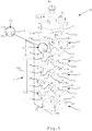
- the crushing rotor 20 comprises discs 22, arranged facing and parallel to each other, connected to a shaft 21.
- Each disc 22 is provided with a central hole 22a in which the shaft 21 is housed.
- the distance between two consecutive discs 22 is defined by a bushing 23 interposed between them. Said bushings can have the same length, so as to keep the same distance between the discs, or a different length.
- All the discs 22 and the bushings 23 can be made in once piece, or preferably, be separate elements couplable to one another.
- the bushings 23 are made in one piece with at least one disc 22.
- the discs 22 can have the same diameter or different diameters. In the variant illustrated, all the discs, except the lower one, have the same diameter.
- the crushing rotor thus configured can be used with a crushing chamber 10 provided with at least one final segment converging toward the outlet 7 of the crushed material. In fact, in this case it is the progressive movement of the inner surface 11 toward the crushing rotor 20 that allows a gradual reduction of the size of the crushed material.
- the crushing chamber can have a substantially constant section, while the discs 22, or at least some of them, can have a diameter increasing toward the outlet 7.
- the discs 22 are integral in rotation with the shaft 21. This constraint can be produced in a known manner, for example through a suitably structured or sized shaft-hole coupling.
- a driving disc 22' has the central hole 22a' with a polygonal section suitable to couple with a respective portion 21a of the shaft 21 shaped in a complementary manner. Rotation is transmitted by said driving disc 22' to the other driven discs 22 through rods 24, or pins, housed in holes 24a passing through two or more consecutive discs 22.
- the tools 25, 26 of the crushing rotor are arranged between two facing discs 22 and are connected thereto preferably in a removable manner.
- Each array of tools 25, 26 comprised between two facing and consecutive discs defines a crushing stage S of the crushing rotor 20.
- the tools 25, 26 are arranged at the peripheral edge 22b of the discs 22, slightly protruding or slightly retracted with respect thereto.
- the crushing rotor 20 comprises a first array of tools 25 that form the first crushing stage S, i.e., the one closest to the inlet 6. Said tools 25 are preferably protruding from the peripheral edge 22a of the discs 22 toward the inner surface 11 of the crushing chamber 10.
- said tools 25 comprise a monolithic block with two lateral faces 25a, diverging toward the inner surface 11, and a substantially flat front face 25b facing said inner surface 11.
- the tools 25 can also have other known shapes typical of the hammers used in crushing rotors of the prior art.
- the subsequent crushing stages S are preferably equipped with tools 26 configured to rotate with respect to the discs 22 about respective axes of rotation Rt, substantially parallel to the axis Rr of the crushing rotor 20.
- These tools 26 have a substantially cylindrical shape and the outer edge is provided with protruding elements.
- the tools 26 are gear shaped or similar.
- said tools can be pivoted on the same rods 24 that transmit rotation from the driving disc 22' to the other discs 22.
- FIG. 5 instead shows the crushing rotor 20 in a complete configuration, i.e., with all the crushing stages S prepared for operation.
- the tools 25, 26 of each crushing stage S are preferably at least two or more, for example three, as in the variant illustrated.
- the tools 25, 26 of a same crushing stage S are equally spaced angularly.
- the tools of different crushing stages S can also be aligned with one another, for example along a same rotation axis Rt, as in the variant illustrated, or staggered between the various stages or, at least, between adjacent stages.
- the tools 25, 26 have a height substantially equal to the distance between the respective discs 22, 22' within which they are arranged.
- this structure allows maximization of the efficacy of the crushing action of the material, which is carried out exploiting substantially the whole of the vertical extension of the inner surface 11 of the crushing chamber 10.
- this structure allows the working faces of the tools, which are facing the inner surface 11, to press and compress the material against said surface in order to crush, deform and/or break it.
- the crushing rotor 20, in the upper part, is provided with distribution blades 27.
- Said distribution blades 27 have the task of conveying the material to be crushed, loaded through the inlet 6, toward the inner surface 11 of the crushing chamber 10 where the tools 25 of the first crushing stage S act.
- the crushing rotor 20 can also be equipped with outlet blades 28 suitable to push the crushed material toward the outlet 7 to facilitate its removal.
- Said blades 27 can be positioned in the last crushing stage S, closest to the outlet 7, alternated with the tools 26, or under said lower stage.
- Parts of material to be crushed are loaded through the inlet 6 into the upper part of the crushing chamber 10.
- the material as a result of rotation of the crushing rotor 20, and of the distribution blades 27, is conveyed toward the inner surface 11 of the crushing chamber, where it is impacted by the tools 25 of the first crushing stage.
- the crushing action takes place in a manner distributed against the inner surface 11 and more precisely against the protruding profiles 12b of the plates 12.
- these protruding profiles 12b create a high resistance to friction of the parts of material on the inner surface 11, facilitating the crushing, deformation and tearing actions of the tools.
- the material to be crushed is then broken until the crushed sub-parts have reached a size that allows them to drop through the spaces between the crushing rotor 20 and the inner surface 11 of the crushing chamber 10, toward the next crushing stage.
- the subsequent crushing stages, and the related tools 26, also operate in the same manner.
- the crushing rotor 20 it is possible to equip the crushing rotor 20 with a number of crushing stages S so as to provide at the outlet parts of material of larger or smaller sizes, according to requirements.
- the shaft 21 is equipped with a different number of discs 22, and therefore of groups of tools, or, alternatively, discs 22 of different diameter are fitted to the shaft 21.
- the crushing rotor 20 is assembled modularly so that it can be reconfigured in a practical and rapid manner.
- the structure of the lateral wall 5 that, as it can open completely, allows the removal and subsequent repositioning of the crushing rotor 20 removing only a very few parts of the apparatus.
- the crushing rotor 20 can be coupled at the top end 20a and lifted with lifting means.
Landscapes
- Engineering & Computer Science (AREA)
- Food Science & Technology (AREA)
- Disintegrating Or Milling (AREA)
- Crushing And Pulverization Processes (AREA)
Applications Claiming Priority (1)
| Application Number | Priority Date | Filing Date | Title |
|---|---|---|---|
| IT102016000111257A IT201600111257A1 (it) | 2016-11-04 | 2016-11-04 | Apparato frantumatore |
Publications (1)
| Publication Number | Publication Date |
|---|---|
| EP3318330A1 true EP3318330A1 (de) | 2018-05-09 |
Family
ID=58163080
Family Applications (1)
| Application Number | Title | Priority Date | Filing Date |
|---|---|---|---|
| EP17199934.5A Withdrawn EP3318330A1 (de) | 2016-11-04 | 2017-11-03 | Zerkleinerungsmaschine |
Country Status (2)
| Country | Link |
|---|---|
| EP (1) | EP3318330A1 (de) |
| IT (1) | IT201600111257A1 (de) |
Cited By (3)
| Publication number | Priority date | Publication date | Assignee | Title |
|---|---|---|---|---|
| EP3791961A1 (de) * | 2019-08-21 | 2021-03-17 | Trenn- und Sortiertechnik GmbH | Prallmühle zur zerkleinerung von feststoffen |
| JP2021065819A (ja) * | 2019-10-20 | 2021-04-30 | ゼンキ工業株式会社 | 回転破砕機 |
| JP2023007534A (ja) * | 2021-07-01 | 2023-01-19 | 富士車輌株式会社 | 破砕装置 |
Families Citing this family (1)
| Publication number | Priority date | Publication date | Assignee | Title |
|---|---|---|---|---|
| CN116159635B (zh) * | 2023-01-06 | 2024-05-14 | 唐河县鑫淼再生资源开发有限公司 | 一种机制砂生产用破碎设备 |
Citations (7)
| Publication number | Priority date | Publication date | Assignee | Title |
|---|---|---|---|---|
| US5911372A (en) | 1997-01-28 | 1999-06-15 | Williams, Jr.; Robert M. | Material reduction apparatus |
| WO2001083111A1 (en) | 2000-04-28 | 2001-11-08 | Officina Meccanica Molinari & C. S.N.C. | Granulator mill with composite rotor comprising offset teeth |
| US7222805B1 (en) | 2003-04-08 | 2007-05-29 | Williams Jr Robert M | Shredder with cage relief |
| US20090194620A1 (en) * | 2008-02-06 | 2009-08-06 | Jason Potter | Drop-in anvils for an impact crushing apparatus |
| US20110101141A1 (en) * | 2008-07-25 | 2011-05-05 | Alexander Koslow | Sphere-producing/comminution machine |
| US20130126647A1 (en) * | 2010-05-21 | 2013-05-23 | Charles Allen Arnold | Comminution Reactor |
| WO2016130924A1 (en) * | 2015-02-12 | 2016-08-18 | Energy Creates Energy Llc | Nautiloid shaped fan housing for a comminution mill |
-
2016
- 2016-11-04 IT IT102016000111257A patent/IT201600111257A1/it unknown
-
2017
- 2017-11-03 EP EP17199934.5A patent/EP3318330A1/de not_active Withdrawn
Patent Citations (7)
| Publication number | Priority date | Publication date | Assignee | Title |
|---|---|---|---|---|
| US5911372A (en) | 1997-01-28 | 1999-06-15 | Williams, Jr.; Robert M. | Material reduction apparatus |
| WO2001083111A1 (en) | 2000-04-28 | 2001-11-08 | Officina Meccanica Molinari & C. S.N.C. | Granulator mill with composite rotor comprising offset teeth |
| US7222805B1 (en) | 2003-04-08 | 2007-05-29 | Williams Jr Robert M | Shredder with cage relief |
| US20090194620A1 (en) * | 2008-02-06 | 2009-08-06 | Jason Potter | Drop-in anvils for an impact crushing apparatus |
| US20110101141A1 (en) * | 2008-07-25 | 2011-05-05 | Alexander Koslow | Sphere-producing/comminution machine |
| US20130126647A1 (en) * | 2010-05-21 | 2013-05-23 | Charles Allen Arnold | Comminution Reactor |
| WO2016130924A1 (en) * | 2015-02-12 | 2016-08-18 | Energy Creates Energy Llc | Nautiloid shaped fan housing for a comminution mill |
Cited By (5)
| Publication number | Priority date | Publication date | Assignee | Title |
|---|---|---|---|---|
| EP3791961A1 (de) * | 2019-08-21 | 2021-03-17 | Trenn- und Sortiertechnik GmbH | Prallmühle zur zerkleinerung von feststoffen |
| JP2021065819A (ja) * | 2019-10-20 | 2021-04-30 | ゼンキ工業株式会社 | 回転破砕機 |
| JP7189617B2 (ja) | 2019-10-20 | 2022-12-14 | ゼンキ工業株式会社 | 回転破砕機 |
| JP2023007534A (ja) * | 2021-07-01 | 2023-01-19 | 富士車輌株式会社 | 破砕装置 |
| JP7713323B2 (ja) | 2021-07-01 | 2025-07-25 | 富士車輌株式会社 | 破砕装置 |
Also Published As
| Publication number | Publication date |
|---|---|
| IT201600111257A1 (it) | 2018-05-04 |
Similar Documents
| Publication | Publication Date | Title |
|---|---|---|
| EP3318330A1 (de) | Zerkleinerungsmaschine | |
| EP2529835B1 (de) | Vorrichtung zum mechanischen Trennen von Materialkonglomeraten aus Materialen unterschiedlicher Dichte und/oder Konsistenz | |
| DE102012104031B4 (de) | Trennvorrichtung für Materialkonglomerate | |
| US5150844A (en) | Apparatus for size reduction of heavy solid waste materials | |
| EP2987556B1 (de) | Zerkleinerungsmaschine | |
| WO2012125834A2 (en) | Conjugate anvil hammer mill | |
| KR101034664B1 (ko) | 건설폐기물용 다단 파쇄기 및 이를 이용한 건설 및 생활폐기물의 중간처리 과정 중에서 발생되는 순환골재 생산시설 | |
| DE69126539T2 (de) | Holzzerkleinerungsvorrichtung | |
| CA1210379A (en) | Screenless screw mill | |
| EP1189701B1 (de) | Umlaufender brecher | |
| CA3008568C (en) | A crusher for rubble | |
| RU2072262C1 (ru) | Измельчитель | |
| DE102017110758B4 (de) | Prallbrecher | |
| KR200456409Y1 (ko) | 경량 잡고체 폐기물 분쇄기 | |
| EP2987555B1 (de) | Rotor | |
| DE19903526B4 (de) | Separationseinrichtung für aus unterschiedlichen Stoffen zusammengesetzte Produkte | |
| EP1001093A1 (de) | Mobile Vorrichtung zum Zerkleinern von Steinen oder dergleichen | |
| GB2341121A (en) | Rotary crusher with polygonal drum. | |
| JP2003260378A (ja) | 破砕機および破砕方法 | |
| DE112009001498T5 (de) | Vertikale Turbo Zerkleinerungsmaschine | |
| DE2000076A1 (de) | Nichtverstopfender Schlagbrecher | |
| WO2012069595A1 (de) | Vorrichtung und verfahren zur materialzerkleinerung | |
| DE656288C (de) | Tellerbrecher | |
| RU53936U1 (ru) | Центробежно-роторный измельчитель дезинтеграторного типа | |
| AT364743B (de) | Granuliermaschine fuer eine anlage fuer die zerkleinerung von abfallmaterial |
Legal Events
| Date | Code | Title | Description |
|---|---|---|---|
| PUAI | Public reference made under article 153(3) epc to a published international application that has entered the european phase |
Free format text: ORIGINAL CODE: 0009012 |
|
| STAA | Information on the status of an ep patent application or granted ep patent |
Free format text: STATUS: THE APPLICATION HAS BEEN PUBLISHED |
|
| AK | Designated contracting states |
Kind code of ref document: A1 Designated state(s): AL AT BE BG CH CY CZ DE DK EE ES FI FR GB GR HR HU IE IS IT LI LT LU LV MC MK MT NL NO PL PT RO RS SE SI SK SM TR |
|
| AX | Request for extension of the european patent |
Extension state: BA ME |
|
| STAA | Information on the status of an ep patent application or granted ep patent |
Free format text: STATUS: REQUEST FOR EXAMINATION WAS MADE |
|
| 17P | Request for examination filed |
Effective date: 20181109 |
|
| RBV | Designated contracting states (corrected) |
Designated state(s): AL AT BE BG CH CY CZ DE DK EE ES FI FR GB GR HR HU IE IS IT LI LT LU LV MC MK MT NL NO PL PT RO RS SE SI SK SM TR |
|
| STAA | Information on the status of an ep patent application or granted ep patent |
Free format text: STATUS: THE APPLICATION IS DEEMED TO BE WITHDRAWN |
|
| 18D | Application deemed to be withdrawn |
Effective date: 20210601 |