EP3318457B1 - Dispositif de frein électromécanique - Google Patents
Dispositif de frein électromécanique Download PDFInfo
- Publication number
- EP3318457B1 EP3318457B1 EP16817559.4A EP16817559A EP3318457B1 EP 3318457 B1 EP3318457 B1 EP 3318457B1 EP 16817559 A EP16817559 A EP 16817559A EP 3318457 B1 EP3318457 B1 EP 3318457B1
- Authority
- EP
- European Patent Office
- Prior art keywords
- brake
- wheel
- control unit
- brake mechanism
- braking force
- Prior art date
- Legal status (The legal status is an assumption and is not a legal conclusion. Google has not performed a legal analysis and makes no representation as to the accuracy of the status listed.)
- Active
Links
Images



Classifications
-
- B—PERFORMING OPERATIONS; TRANSPORTING
- B60—VEHICLES IN GENERAL
- B60T—VEHICLE BRAKE CONTROL SYSTEMS OR PARTS THEREOF; BRAKE CONTROL SYSTEMS OR PARTS THEREOF, IN GENERAL; ARRANGEMENT OF BRAKING ELEMENTS ON VEHICLES IN GENERAL; PORTABLE DEVICES FOR PREVENTING UNWANTED MOVEMENT OF VEHICLES; VEHICLE MODIFICATIONS TO FACILITATE COOLING OF BRAKES
- B60T8/00—Arrangements for adjusting wheel-braking force to meet varying vehicular or ground-surface conditions, e.g. limiting or varying distribution of braking force
- B60T8/17—Using electrical or electronic regulation means to control braking
-
- B—PERFORMING OPERATIONS; TRANSPORTING
- B60—VEHICLES IN GENERAL
- B60T—VEHICLE BRAKE CONTROL SYSTEMS OR PARTS THEREOF; BRAKE CONTROL SYSTEMS OR PARTS THEREOF, IN GENERAL; ARRANGEMENT OF BRAKING ELEMENTS ON VEHICLES IN GENERAL; PORTABLE DEVICES FOR PREVENTING UNWANTED MOVEMENT OF VEHICLES; VEHICLE MODIFICATIONS TO FACILITATE COOLING OF BRAKES
- B60T8/00—Arrangements for adjusting wheel-braking force to meet varying vehicular or ground-surface conditions, e.g. limiting or varying distribution of braking force
- B60T8/17—Using electrical or electronic regulation means to control braking
- B60T8/1755—Brake regulation specially adapted to control the stability of the vehicle, e.g. taking into account yaw rate or transverse acceleration in a curve
-
- B—PERFORMING OPERATIONS; TRANSPORTING
- B60—VEHICLES IN GENERAL
- B60T—VEHICLE BRAKE CONTROL SYSTEMS OR PARTS THEREOF; BRAKE CONTROL SYSTEMS OR PARTS THEREOF, IN GENERAL; ARRANGEMENT OF BRAKING ELEMENTS ON VEHICLES IN GENERAL; PORTABLE DEVICES FOR PREVENTING UNWANTED MOVEMENT OF VEHICLES; VEHICLE MODIFICATIONS TO FACILITATE COOLING OF BRAKES
- B60T1/00—Arrangements of braking elements, i.e. of those parts where braking effect occurs specially for vehicles
- B60T1/02—Arrangements of braking elements, i.e. of those parts where braking effect occurs specially for vehicles acting by retarding wheels
- B60T1/06—Arrangements of braking elements, i.e. of those parts where braking effect occurs specially for vehicles acting by retarding wheels acting otherwise than on tread, e.g. employing rim, drum, disc, or transmission or on double wheels
- B60T1/065—Arrangements of braking elements, i.e. of those parts where braking effect occurs specially for vehicles acting by retarding wheels acting otherwise than on tread, e.g. employing rim, drum, disc, or transmission or on double wheels employing disc
-
- B—PERFORMING OPERATIONS; TRANSPORTING
- B60—VEHICLES IN GENERAL
- B60T—VEHICLE BRAKE CONTROL SYSTEMS OR PARTS THEREOF; BRAKE CONTROL SYSTEMS OR PARTS THEREOF, IN GENERAL; ARRANGEMENT OF BRAKING ELEMENTS ON VEHICLES IN GENERAL; PORTABLE DEVICES FOR PREVENTING UNWANTED MOVEMENT OF VEHICLES; VEHICLE MODIFICATIONS TO FACILITATE COOLING OF BRAKES
- B60T1/00—Arrangements of braking elements, i.e. of those parts where braking effect occurs specially for vehicles
- B60T1/02—Arrangements of braking elements, i.e. of those parts where braking effect occurs specially for vehicles acting by retarding wheels
- B60T1/06—Arrangements of braking elements, i.e. of those parts where braking effect occurs specially for vehicles acting by retarding wheels acting otherwise than on tread, e.g. employing rim, drum, disc, or transmission or on double wheels
- B60T1/067—Arrangements of braking elements, i.e. of those parts where braking effect occurs specially for vehicles acting by retarding wheels acting otherwise than on tread, e.g. employing rim, drum, disc, or transmission or on double wheels employing drum
-
- B—PERFORMING OPERATIONS; TRANSPORTING
- B60—VEHICLES IN GENERAL
- B60T—VEHICLE BRAKE CONTROL SYSTEMS OR PARTS THEREOF; BRAKE CONTROL SYSTEMS OR PARTS THEREOF, IN GENERAL; ARRANGEMENT OF BRAKING ELEMENTS ON VEHICLES IN GENERAL; PORTABLE DEVICES FOR PREVENTING UNWANTED MOVEMENT OF VEHICLES; VEHICLE MODIFICATIONS TO FACILITATE COOLING OF BRAKES
- B60T13/00—Transmitting braking action from initiating means to ultimate brake actuator with power assistance or drive; Brake systems incorporating such transmitting means, e.g. air-pressure brake systems
- B60T13/74—Transmitting braking action from initiating means to ultimate brake actuator with power assistance or drive; Brake systems incorporating such transmitting means, e.g. air-pressure brake systems with electrical assistance or drive
- B60T13/741—Transmitting braking action from initiating means to ultimate brake actuator with power assistance or drive; Brake systems incorporating such transmitting means, e.g. air-pressure brake systems with electrical assistance or drive acting on an ultimate actuator
-
- B—PERFORMING OPERATIONS; TRANSPORTING
- B60—VEHICLES IN GENERAL
- B60T—VEHICLE BRAKE CONTROL SYSTEMS OR PARTS THEREOF; BRAKE CONTROL SYSTEMS OR PARTS THEREOF, IN GENERAL; ARRANGEMENT OF BRAKING ELEMENTS ON VEHICLES IN GENERAL; PORTABLE DEVICES FOR PREVENTING UNWANTED MOVEMENT OF VEHICLES; VEHICLE MODIFICATIONS TO FACILITATE COOLING OF BRAKES
- B60T17/00—Component parts, details, or accessories of power brake systems not covered by groups B60T8/00, B60T13/00 or B60T15/00, or presenting other characteristic features
- B60T17/18—Safety devices; Monitoring
- B60T17/22—Devices for monitoring or checking brake systems; Signal devices
- B60T17/221—Procedure or apparatus for checking or keeping in a correct functioning condition of brake systems
-
- F—MECHANICAL ENGINEERING; LIGHTING; HEATING; WEAPONS; BLASTING
- F16—ENGINEERING ELEMENTS AND UNITS; GENERAL MEASURES FOR PRODUCING AND MAINTAINING EFFECTIVE FUNCTIONING OF MACHINES OR INSTALLATIONS; THERMAL INSULATION IN GENERAL
- F16D—COUPLINGS FOR TRANSMITTING ROTATION; CLUTCHES; BRAKES
- F16D65/00—Parts or details
- F16D65/14—Actuating mechanisms for brakes; Means for initiating operation at a predetermined position
- F16D65/16—Actuating mechanisms for brakes; Means for initiating operation at a predetermined position arranged in or on the brake
- F16D65/18—Actuating mechanisms for brakes; Means for initiating operation at a predetermined position arranged in or on the brake adapted for drawing members together, e.g. for disc brakes
-
- F—MECHANICAL ENGINEERING; LIGHTING; HEATING; WEAPONS; BLASTING
- F16—ENGINEERING ELEMENTS AND UNITS; GENERAL MEASURES FOR PRODUCING AND MAINTAINING EFFECTIVE FUNCTIONING OF MACHINES OR INSTALLATIONS; THERMAL INSULATION IN GENERAL
- F16D—COUPLINGS FOR TRANSMITTING ROTATION; CLUTCHES; BRAKES
- F16D65/00—Parts or details
- F16D65/14—Actuating mechanisms for brakes; Means for initiating operation at a predetermined position
- F16D65/16—Actuating mechanisms for brakes; Means for initiating operation at a predetermined position arranged in or on the brake
- F16D65/18—Actuating mechanisms for brakes; Means for initiating operation at a predetermined position arranged in or on the brake adapted for drawing members together, e.g. for disc brakes
- F16D65/183—Actuating mechanisms for brakes; Means for initiating operation at a predetermined position arranged in or on the brake adapted for drawing members together, e.g. for disc brakes with force-transmitting members arranged side by side acting on a spot type force-applying member
-
- F—MECHANICAL ENGINEERING; LIGHTING; HEATING; WEAPONS; BLASTING
- F16—ENGINEERING ELEMENTS AND UNITS; GENERAL MEASURES FOR PRODUCING AND MAINTAINING EFFECTIVE FUNCTIONING OF MACHINES OR INSTALLATIONS; THERMAL INSULATION IN GENERAL
- F16D—COUPLINGS FOR TRANSMITTING ROTATION; CLUTCHES; BRAKES
- F16D65/00—Parts or details
- F16D65/14—Actuating mechanisms for brakes; Means for initiating operation at a predetermined position
- F16D65/16—Actuating mechanisms for brakes; Means for initiating operation at a predetermined position arranged in or on the brake
- F16D65/22—Actuating mechanisms for brakes; Means for initiating operation at a predetermined position arranged in or on the brake adapted for pressing members apart, e.g. for drum brakes
-
- B—PERFORMING OPERATIONS; TRANSPORTING
- B60—VEHICLES IN GENERAL
- B60T—VEHICLE BRAKE CONTROL SYSTEMS OR PARTS THEREOF; BRAKE CONTROL SYSTEMS OR PARTS THEREOF, IN GENERAL; ARRANGEMENT OF BRAKING ELEMENTS ON VEHICLES IN GENERAL; PORTABLE DEVICES FOR PREVENTING UNWANTED MOVEMENT OF VEHICLES; VEHICLE MODIFICATIONS TO FACILITATE COOLING OF BRAKES
- B60T2270/00—Further aspects of brake control systems not otherwise provided for
- B60T2270/40—Failsafe aspects of brake control systems
- B60T2270/402—Back-up
-
- B—PERFORMING OPERATIONS; TRANSPORTING
- B60—VEHICLES IN GENERAL
- B60T—VEHICLE BRAKE CONTROL SYSTEMS OR PARTS THEREOF; BRAKE CONTROL SYSTEMS OR PARTS THEREOF, IN GENERAL; ARRANGEMENT OF BRAKING ELEMENTS ON VEHICLES IN GENERAL; PORTABLE DEVICES FOR PREVENTING UNWANTED MOVEMENT OF VEHICLES; VEHICLE MODIFICATIONS TO FACILITATE COOLING OF BRAKES
- B60T2270/00—Further aspects of brake control systems not otherwise provided for
- B60T2270/40—Failsafe aspects of brake control systems
- B60T2270/414—Power supply failure
-
- F—MECHANICAL ENGINEERING; LIGHTING; HEATING; WEAPONS; BLASTING
- F16—ENGINEERING ELEMENTS AND UNITS; GENERAL MEASURES FOR PRODUCING AND MAINTAINING EFFECTIVE FUNCTIONING OF MACHINES OR INSTALLATIONS; THERMAL INSULATION IN GENERAL
- F16D—COUPLINGS FOR TRANSMITTING ROTATION; CLUTCHES; BRAKES
- F16D2121/00—Type of actuator operation force
- F16D2121/18—Electric or magnetic
- F16D2121/24—Electric or magnetic using motors
Definitions
- This invention relates to an electric brake device having a friction-receiving member that rotates together with a wheel; and a friction-applying member that moves while being powered by an electric actuator, and obtains the braking force by pressing the friction-applying member against the friction-receiving member.
- This invention made in consideration of the above-described circumstances, is to improve convenience of the electric brake device.
- the braking force is reduced for a wheel positioned opposite to the defective wheel both in the width direction and the length direction, that is, both in the front-rear direction and the crosswise direction, posing an advantage of balancing the braking force in the vehicle-width direction.
- each of the brake mechanisms obtains the braking force by pressing, with the aid of the actuator, the friction-applying member against the friction-receiving member that rotates together with the wheel, posing an advantage of improving responsiveness to the brake operation as compared with the conventional hydraulic brake, and enabling various modes of brake operation adopted to the vehicle conditions.
- a disk brake system with a high heat radiation performance is built by employing a brake disk as the friction-receiving member, and a brake pad as the friction-applying member, posing an advantage of improving durability of the brake mechanism.
- control units are provided one by one to the front-left wheel brake mechanism and the front-right wheel brake mechanism, and a single control unit is allocated to the left and right brake mechanisms for rear wheels, so that even if one control unit should go into failure, the residual brake mechanism for the front wheels remains controllable, posing an advantage of enhancing redundancy of the front wheel brake having a higher importance in braking.
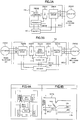
- FIG. 1 is an explanatory drawing illustrating a configuration of an electric brake device 10 according to an embodiment.
- the wheels 12, 14, 16, 18 are the front-left wheel 12, the front-right wheel 14, the rear-left wheel 16, and the rear-right wheel 18.
- the front-left wheel brake mechanism 20 to the front-left wheel 12; the front-right wheel brake mechanism 22 to the front-right wheel 14; the rear-left wheel brake mechanism 24 to the rear-left wheel 16; and the rear-right wheel brake mechanism 26 to the rear-right wheel 18, respectively, making it possible to brake the respective wheels.
- the individual brake mechanisms 20, 22, 24, 26 configure service brakes, and are respectively provided with control units 28, 30, 32.
- the front-left wheel brake mechanism 20 is controlled by the front-left wheel control unit 28, the front-right wheel brake mechanism 22 by the front-right wheel control unit 30, and the rear-left wheel brake mechanism 24 and the rear-right wheel brake mechanism 26 by the rear-left/right wheel control unit 32, respectively.
- the vehicle control unit 50 is connected to a brake pedal (service brake operating unit) 52 and a parking brake operating unit 54, and outputs, when the brake pedal 52 or the parking brake operating unit 54 is operated, a control signal that directs the individual control units 28, 30, 32, 38 to activate the brake.
- a brake pedal service brake operating unit
- a parking brake operating unit 54 outputs, when the brake pedal 52 or the parking brake operating unit 54 is operated, a control signal that directs the individual control units 28, 30, 32, 38 to activate the brake.
- control units 28, 30, 32, 38 may be connected directly so as to allow them to monitor each other.
- each of the brake mechanisms 20, 22, 24, 26 has a brake disk (friction-receiving member) that rotates together with the wheel, and an electric caliper that has a brake pad movable between the pressing position and the non-pressing position relative to the brake disk by aid of the electric actuator.
- FIG. 3 is an explanatory drawing illustrating an exemplary schematic configuration of the control unit, wherein FIG. 3A illustrates the control unit that controls one brake mechanism, such as the front-left wheel control unit 28 (or the front-right wheel control unit 30), and FIG. 3B illustrates the control unit that controls two brake mechanisms, such as the rear-left/right wheel control unit 32.
- FIG. 3A illustrates the control unit that controls one brake mechanism, such as the front-left wheel control unit 28 (or the front-right wheel control unit 30)
- FIG. 3B illustrates the control unit that controls two brake mechanisms, such as the rear-left/right wheel control unit 32.
- the microcomputer 2802 is connected to the vehicle control unit 50 (not illustrated in FIG. 3 ), and, when a brake activation instruction is issued from the vehicle control unit 50, activates the bridge circuit 2806 to convert electric power of the main battery 40 into three-phase AC power, and supplies the power to the electric actuator 2002 of the brake mechanism (the front-left wheel brake mechanism 20 in FIG. 3A ) to thereby activate the electric actuator 2002.
- the front-left wheel control unit 28 contains a power source circuit of the front-left wheel brake mechanism 20.
- the rear-left/right wheel control unit 32 is configured to contain a dual microcomputer 3202, two integrated circuits 3204, 3206, two bridge circuits 3208, 3210, and a power source regulator 3212.
- a power source regulator 3212 and the bridge circuits 3208, 3210 are individually connected to the main battery 40.
- the dual microcomputer 3202 is connected to the vehicle control unit 50, and, when a brake activation instruction was issued from the vehicle control unit 50, activates the bridge circuits 3208, 3210 to convert electric power of the main battery 40 into three-phase AC power, and supplies the power to the electric actuators 2402, 2602 of the brake mechanism (the rear-left wheel brake mechanism 24 and the rear-right wheel brake mechanism 26 in FIG. 3B ) to thereby activate the electric actuators 2402, 2602.
- the electric brake mechanism controls operations of the brake mechanism by electric signals, so that the operations of the brake mechanism may be controlled finely depending on situations, thus making it no more necessary to use hydraulic piping, and making it possible to considerably reduce the vehicle weight.
- the rear-left wheel 16 and the rear-right wheel 18 are further provided with the parking brake mechanisms 34, 36, respectively.
- the parking brake mechanisms 34, 36 are mainly used for preventing parked vehicles from moving.
- the parking brake mechanisms 34, 36 are controlled by the parking control unit 38.
- each of the parking brake mechanisms 34, 36 is an electric parking brake (EPB), and may be configured in various ways.
- EPB electric parking brake
- FIG. 2 is an explanatory drawing illustrating an exemplary configuration of the parking brake in the electric brake device 10.
- ECU 28 corresponds to the front-left wheel control unit 28, ECU 30 to the front-right wheel control unit 30, and ECU 32 to the rear-left/right wheel control unit 32.
- EPB 38 corresponds to the parking control unit 38.
- the rear-left wheel brake mechanism 24 and the rear-right wheel brake mechanism 26 also function as the parking brake mechanisms 34, 36, respectively.
- the parking control unit 38 activates the electric actuators of the rear-left wheel brake mechanism 24 and the rear-right wheel brake mechanism 26, the brake pads then move to the pressing position relative to the brake disk, to thereby apply braking force to the rear-left/right wheels 16, 18.
- FIG. 2B illustrates an exemplary configuration of the parking brake mechanisms 34, 36 based on the drum-in-hat (DIH) system, in which a brake drum is disposed in the brake disk of the rear-left wheel brake mechanism 24 and the rear-right wheel brake mechanism 26.
- DIH drum-in-hat
- the parking brake mechanisms 34, 36 have brake drums respectively disposed in the hats positioned at the center of the brake disks of the rear-left wheel brake mechanism 24 and the rear-right wheel brake mechanism 26, and rotate together with the wheels; and brake shoes provided inside the individual brake drums, and movable between the pressing position and the non-pressing position relative to the brake drums while being powered by the electric actuators for parking.
- the parking control unit 38 activates the electric actuator for parking, moves the brake shoes of the parking brake mechanisms 34, 36 to the pressing position relative to the brake drum, to thereby apply the braking force to the rear-left/right wheels 16, 18.
- the parking brake mechanisms 34, 36 have the brake drums that are positioned at the center of the brake disks of the rear-left wheel brake mechanism 24 and the rear-right wheel brake mechanism 26, and rotate together with the wheels; and the brake shoes provided inside the individual brake drums, and movable between the pressing position and the non-pressing position relative to the brake drums while being powered by the electric actuator for parking.
- the parking control unit 38 is configured integrally with each of the parking brake mechanisms 34, 36.
- the brake shoe In the normal state (non-braking state for parking), the brake shoe is energized towards the inner circumference of the brake drum, and is kept at the non-pressing position away from the brake drum. Between one end of the brake shoe and one end of the brake shoe, a motor with a linear motion mechanism is attached.
- the brake shoe When the motor of the drum-type parking rotates, the brake shoe is pushed on one end while mediated by a linear motion mechanism. When the brake shoe is pressed, it moves towards the outer circumference of the brake drum, and comes into the pressing position relative to the brake drum.
- the electric brake device 10 uses three control units 28, 30, 32 to control four brake mechanisms 20, 22, 24, 26 provided to four wheels 12, 14, 16, 18, and in case of failure of two of these control units, three wheels will become uncontrollable, and thereby the vehicle may be off-balanced.
- the electric brake device 10 is designed to leave at least two wheels brakable, so as to keep the steering performance of the vehicle, and so as to reserve a level of braking force necessary to stop the vehicle.
- FIG. 4 to FIG. 7 are explanatory drawings illustrating changes in the braking force in case of failure of the control unit.
- the rear-left/right wheel control unit 32 reduces the braking force of the rear wheel braking mechanism positioned opposite to such one defective control unit in the crosswise direction, and increases the braking force of the rear wheel braking mechanism positioned on the same side with the one defective control unit in the crosswise direction, meanwhile the other one of the front-left wheel control unit 28 and the front-right wheel control unit 30 increases the braking force of the front wheel braking mechanism positioned opposite to the one defective control unit in the crosswise direction.
- both of the front-left wheel brake mechanism 20 and the front-right wheel brake mechanism 22 (FR1, 2) brake the front-left/right wheels 12, 14 with predetermined braking force P1; and, both of the rear-left wheel brake mechanism 24 and the rear-right wheel brake mechanism 26'(RR1, 2) brake the rear-left/right wheels 16, 18 with predetermined braking force P2 ( ⁇ P1), where the braking force totals P3.
- the front-left wheel control unit 28 and the front-left wheel control unit 30 increase the braking force of the front-left wheel brake mechanism 20 and the front-right wheel brake mechanism 22, respectively.
- the parking control unit 38 activates the parking brake mechanisms 34, 36 to generate the braking force for the rear-left wheel 16 and the rear-right wheel 18.
- both of the front-left wheel brake mechanism 20 and the front-right wheel brake mechanism 22 (FR1, 2) brake the front-left/right wheels 12, 14 with predetermined braking force P1
- both of the rear-left wheel brake mechanism 24 and the rear-right wheel brake mechanism 26 (RR1, 2) brake the rear-left/right wheels 16, 18 with predetermined braking force P2 ( ⁇ P1), where the braking force totals P3.
- the braking force of the rear-right wheel brake mechanism 26 positioned diagonal to the defective front-left wheel brake mechanism 20 is reduced to stabilize the vehicle posture, and the braking force of the residual brake mechanisms 22, 24 is increased, to thereby reserve a sufficient level of total braking force.
- rear-left/right wheel control unit 32 elevates the braking force of the rear-right wheel brake mechanism 26 (RR2), having been lowered, so as to agree with the braking force of the rear-left wheel brake mechanism 24 (RR1). In this way, it now becomes possible to balance the braking force in the vehicle crosswise direction, and to reserve the braking force necessary for braking the vehicle by increasing the total braking force.
- both of the front-left wheel brake mechanism 20 and the front-right wheel brake mechanism 22 (FR1, 2) brake the front-left/right wheels 12, 14 with predetermined braking force P1
- both of the rear-left wheel brake mechanism 24 and the rear-right wheel brake mechanisms 26 (RR1, 2) brake the rear-left/right wheels 16, 18 with predetermined braking force P2 ( ⁇ P1), where the braking force totals P3.
- the rear-left/right wheel control unit 32 reduces the braking force of the rear-right wheel brake mechanism 26 (RR2), and increases the braking force of the rear-left wheel brake mechanism 24 (RR1).
- the front-right wheel control unit 30 increases the braking force of the front-right wheel brake mechanism 22 (FR2).
- the braking force of the rear-right wheel brake mechanism 26 positioned diagonal to the defective front-left wheel brake mechanism 20 is reduced to stabilize the vehicle posture, and the braking force of the residual brake mechanisms 22, 24 is increased, to thereby reserve a sufficient level of total braking force.
- the front-right wheel control unit 30 zeros the braking force of the front-right wheel brake mechanism 22 (FR2) to stop braking of the front wheels 12, 14. This is for the purpose of preventing the vehicle posture from being off-balanced due to lateral unbalance of the braking force.
- the parking control unit 38 then activates the parking brake mechanisms 34, 36 to brake the rear wheels 16, 18.
- the braking force of the parking brake mechanisms 34, 36 is smaller than those of the rear-left wheel brake mechanism 24 and the rear-right wheel brake mechanism 26 that are service brakes, it can provide a certain level of braking force to the rear wheels 16, 18.
- the other one of the front-left wheel control unit 28 and the front-right wheel control unit 30 reduces the braking force of the front wheel braking mechanism positioned opposite to such one defective control unit in the crosswise direction, and the parking control unit 38 activates the parking brake mechanisms 34, 36 to generate the braking force for the rear-left wheel 16 and the rear-right wheel 18.
- both of the front-left wheel control unit 28 and the front-right wheel control unit 30 increase the braking force of the front-left wheel brake mechanism 20 and the front-right wheel brake mechanism 22 (FR1, 2), respectively.
- the parking control unit 38 activates the parking brake mechanisms 34, 36 to brake the rear wheels 16, 18.
- the non-defective front wheel control unit zeros the braking force of the front wheel braking mechanism to be controlled, so as to allow only the parking brake mechanisms 34, 36 to perform braking.
- control units 28, 30 are allocated one by one to the front-left wheel brake mechanism 20 and the front-right wheel brake mechanism 22, and a single control unit 32 is allocated to the left and right brake mechanisms 24, 26 for rear wheels, so that even if one control unit should go into failure, the residual brake mechanism for the front wheel remains controllable, posing an advantage of enhancing redundancy of the front wheel brake whose importance in braking is higher.
- the braking force is controlled so as to be balanced between braking forces of the left and right front wheels, and between braking forces of the left and right rear wheels, posing an advantage of balancing the braking force in the vehicle crosswise direction, and stabilizing the vehicle posture during braking.
- the braking force both of the front-left wheel brake mechanism 20 and the front-right wheel brake mechanism 22 are increased, posing an advantage of achieving a braking force nearly equal to that before the failure, while balancing the braking force in the vehicle crosswise direction.
- the parking brake mechanisms 34, 36 are further activated to generate the braking force for the rear-left wheel 16 and the rear-right wheel 18, so that a higher level of braking force may be obtained.
- the individual brake mechanisms 20, 22, 24, 26 obtain the braking force by pressing the friction-applying member, while being powered by the electric actuator, against the friction-receiving member that rotates together with the wheel, posing an advantage of improving responsiveness to the brake operation as compared with the conventional hydraulic brake, and enabling various modes of brake operation adopted to the vehicle conditions.
- a disk brake system with a high heat radiation performance is built by employing a brake disk as the friction-receiving member, and a brake pad as the friction-applying member, posing an advantage of improving durability of the brake mechanism.
- the device will be advantageous in terms of reducing vehicle weight and simplifying vehicle configuration, as compared with the case where a dedicated parking brake mechanism is provided.
- the device will be advantageous in terms of relieving the load of the individual brake mechanisms, as compared with the case where the rear-left wheel brake mechanism 24 and the rear-right wheel brake mechanism 26 also function as the parking brake mechanisms 34, 36.
- the electric brake device 10 has two batteries for supplying power to the brake mechanisms 20, 22, 24, 26, so that if the main battery 40 should go into failure, the sub-battery 42 can activate the brake mechanisms 20, 22, 24, 26, posing an advantage of improving redundancy of the brake mechanisms 20, 22, 24, 26.
- the four wheels of vehicle include a first wheel pair composed of a first wheel and a second wheel arranged leaving a space in between in the width direction of vehicle, and a second wheel pair composed of a third wheel and a fourth wheel arranged leaving a space in between in the width direction, and arranged leaving a space from the first wheel pair in the length direction of vehicle, where the first wheel corresponds to the front-left wheel 12, the second wheel to the front-right wheel 14, the third wheel to the rear-left wheel 16, and the fourth wheel to the rear-right wheel 18, the definition may alternatively be such that the first wheel corresponds to the rear-left wheel 16, the second wheel to the rear-right wheel 18, the third wheel to the front-left wheel 12, and the fourth wheel to the front-right wheel 14.
- the brake mechanisms 24, 26 for the rear-left/right wheels 16, 18 will be controlled independently by the respective control units (first control unit, second control unit), and the brake mechanisms 20, 22 for the front-left/right wheels 12, 14 will be controlled by a single control unit (third control unit).
Landscapes
- Engineering & Computer Science (AREA)
- Mechanical Engineering (AREA)
- Transportation (AREA)
- General Engineering & Computer Science (AREA)
- Valves And Accessory Devices For Braking Systems (AREA)
- Regulating Braking Force (AREA)
- Braking Systems And Boosters (AREA)
Claims (13)
- Dispositif de frein électrique (10) pour un véhicule qui comporte une première paire de roues (12, 14) qui est constituée par une première roue et une deuxième roue qui sont agencées en laissant un espace entre elles dans la direction de largeur du véhicule, et une seconde paire de roues (16, 18) qui est constituée par une troisième roue et une quatrième roue qui sont agencées en laissant un espace entre elles dans la direction de largeur du véhicule, et qui est agencée en laissant un espace par rapport à la première paire de roues dans la direction de longueur du véhicule,
le dispositif de frein électrique comprenant au moins trois unités de commande :une première unité de commande (28) qui commande un premier mécanisme de frein pour freiner la première roue ;une deuxième unité de commande (30) qui commande un deuxième mécanisme de frein pour freiner la deuxième roue ; etune troisième unité de commande (32) qui commande un troisième mécanisme de frein pour freiner la troisième roue, et un quatrième mécanisme de frein pour freiner la quatrième roue ;un mécanisme de frein de parcage (34, 36) qui applique une force de freinage sur chaque roue prise parmi la troisième roue et la quatrième roue ; etune unité de commande de parcage (38) qui commande le mécanisme de frein de parcage ;caractérisé en ce que :
dans le cas d'une défaillance de la troisième unité de commande, l'unité de commande de parcage active le mécanisme de frein de parcage afin de générer une force de freinage pour la troisième roue et la quatrième roue ; et dans lequel :
dans le cas d'une défaillance de soit la première unité de commande, soit la deuxième unité de commande et également de la troisième unité de commande, l'autre unité de commande prise parmi la première unité de commande et la deuxième unité de commande réduit la force de freinage du mécanisme de freinage qui est positionné à l'opposé de l'unité de commande en question dans la direction de largeur, et l'unité de commande de parcage active le mécanisme de frein de parcage afin de générer une force de freinage pour la troisième roue et la quatrième roue. - Dispositif de frein électrique selon la revendication 1, dans lequel, dans le cas d'un dysfonctionnement de freinage au niveau d'une quelconque roue prise parmi la première roue (12), la deuxième roue (14), la troisième roue (16) et la quatrième roue (18), l'unité de commande (28, 30, 32) réduit la force de freinage pour une roue qui est positionnée à l'opposé de la roue défectueuse à la fois dans la direction de largeur et dans la direction de longueur.
- Dispositif de frein électrique selon la revendication 1 ou 2, dans lequel, dans le cas d'un dysfonctionnement de freinage au niveau de deux quelconques roues ou plus prises parmi la première roue (12), la deuxième roue (14), la troisième roue (16) et la quatrième roue (18), l'unité de commande est configurée pour commander la force de freinage de telle sorte que les forces de freinage de la première roue et de la deuxième roue soient équilibrées et que les forces de freinage de la troisième roue et de la quatrième roue soient équilibrées.
- Dispositif de frein électrique selon l'une quelconque des revendications 1 à 3, dans lequel, dans le cas d'une défaillance de soit la première unité de commande (28), soit la deuxième unité de commande (30), la troisième unité de commande (32) réduit la force de freinage de soit le troisième mécanisme de frein, soit le quatrième mécanisme de frein qui est positionné à l'opposé de l'unité de commande en question dans la direction de largeur et augmente la force de freinage de soit le troisième mécanisme de frein, soit le quatrième mécanisme de frein qui est positionné sur le même côté que l'unité de commande en question dans la direction de largeur, et l'autre unité de commande prise parmi la première unité de commande (28) et la deuxième unité de commande (30) augmente la force de freinage du mécanisme de frein qui est positionné à l'opposé de l'unité de commande en question dans la direction de largeur.
- Dispositif de frein électrique selon l'une quelconque des revendications 1 à 4, dans lequel, dans le cas d'une défaillance de la troisième unité de commande (32), la première unité de commande (28) et la deuxième unité de commande augmentent respectivement la force de freinage du premier mécanisme de frein (20) et du deuxième mécanisme de frein (22).
- Dispositif de frein électrique selon l'une quelconque des revendications 1 à 5, dans lequel, dans le cas d'une défaillance de la première unité de commande (28) et de la deuxième unité de commande (30), la troisième unité de commande (32) augmente de façon individuelle la force de freinage du troisième mécanisme de frein et du quatrième mécanisme de frein.
- Dispositif de frein électrique selon l'une quelconque des revendications 1 à 6, dans lequel chacun des mécanismes de frein (20, 22, 24, 26) comprend un élément de réception de friction qui est entraîné en rotation en association avec la roue ; et un élément d'application de friction qui est déplacé tandis qu'il est alimenté par un actionneur électrique, et obtient la force de freinage par pression de l'élément d'application de friction contre l'élément de réception de friction.
- Dispositif de frein électrique selon la revendication 7, dans lequel chacun des mécanismes de frein (20, 22, 24, 26) comprend un disque de frein qui est entraîné en rotation avec la roue, et un étrier électrique qui comporte un patin de frein qui peut être déplacé entre la position de pression et la position de non pression par rapport au disque de frein à l'aide de l'actionneur électrique.
- Dispositif de frein électrique selon la revendication 8, dans lequel le troisième mécanisme de frein (24, 34) et le quatrième mécanisme de frein (26, 36) fonctionnent également en tant que mécanisme de frein de parcage, et l'unité de commande de parcage (38) active le frein de parcage en déplaçant les patins de frein du troisième mécanisme de frein et du quatrième mécanisme de frein jusqu'à la position de pression par rapport au disque de frein.
- Dispositif de frein électrique selon la revendication 8, dans lequel le mécanisme de frein de parcage (34, 36) comprend un tambour de frein qui est prévu dans une coiffe qui est positionnée au niveau du centre du disque de frein de chaque mécanisme de frein pris parmi le troisième mécanisme de frein et le quatrième mécanisme de frein, et peut être entraîné en rotation en association avec la roue ; et un sabot de frein qui est prévu dans chacun des tambours de frein et qui peut être déplacé entre la position de pression et la position de non pression par rapport à chaque tambour de frein à l'aide d'un actionneur électrique pour le parcage, et l'unité de commande de parcage (38) active le frein de parcage en déplaçant le sabot de frein du mécanisme de frein de parcage jusqu'à la position de pression par rapport au tambour de frein.
- Dispositif de frein électrique selon la revendication 8, dans lequel le mécanisme de frein de parcage (34, 36) comprend un tambour de frein qui est prévu dans une coiffe qui est positionnée au niveau du centre du disque de frein de chaque mécanisme de frein pris parmi le troisième mécanisme de frein (24) et le quatrième mécanisme de frein (26), et peut être entraîné en rotation avec la roue ; et un sabot de frein qui est prévu dans chacun des tambours de frein et qui peut être déplacé entre la position de pression et la position de non pression par rapport à chaque tambour de frein à l'aide d'un actionneur électrique à déplacement linéaire, et l'unité de commande de parcage (38) active le frein de parcage en déplaçant le sabot de frein du mécanisme de frein de parcage (34, 36) jusqu'à la position de pression par rapport au tambour de frein.
- Dispositif de frein électrique selon l'une quelconque des revendications 1 à 11,
dans lequel chacun des mécanismes de frein (20, 22, 24, 26) est connecté à une batterie principale et à une batterie de secours qui jouent le rôle de sources de puissance pour commander et activer les mécanismes de frein et, dans le cas d'une défaillance de la batterie principale, la source de puissance pour chaque mécanisme de frein est commutée sur la batterie de secours. - Dispositif de frein électrique selon l'une quelconque des revendications 1 à 12, dans lequel :la première roue (12) est la roue avant gauche, la deuxième roue (14) est la roue avant droite, la troisième roue (16) est la roue arrière gauche et la quatrième roue (18) est la roue arrière droite ;le premier mécanisme de frein (20) est le mécanisme de frein de roue avant gauche, le deuxième mécanisme de frein (22) est le mécanisme de frein de roue avant droite, le troisième mécanisme de frein (24, 34) est le mécanisme de frein de roue arrière gauche et le quatrième mécanisme de frein (26, 36) est le mécanisme de frein de roue arrière droite ; etla première unité de commande (28) est l'unité de commande de roue avant gauche, la deuxième unité de commande (30) est l'unité de commande de roue avant droite et la troisième unité de commande (32) est l'unité de commande de roue arrière gauche/droite.
Applications Claiming Priority (2)
| Application Number | Priority Date | Filing Date | Title |
|---|---|---|---|
| JP2015133444A JP6575175B2 (ja) | 2015-07-02 | 2015-07-02 | 電動ブレーキ装置 |
| PCT/JP2016/063798 WO2017002450A1 (fr) | 2015-07-02 | 2016-05-10 | Dispositif de frein électromécanique |
Publications (3)
| Publication Number | Publication Date |
|---|---|
| EP3318457A1 EP3318457A1 (fr) | 2018-05-09 |
| EP3318457A4 EP3318457A4 (fr) | 2019-03-06 |
| EP3318457B1 true EP3318457B1 (fr) | 2021-09-22 |
Family
ID=57608080
Family Applications (1)
| Application Number | Title | Priority Date | Filing Date |
|---|---|---|---|
| EP16817559.4A Active EP3318457B1 (fr) | 2015-07-02 | 2016-05-10 | Dispositif de frein électromécanique |
Country Status (4)
| Country | Link |
|---|---|
| US (1) | US20170240148A1 (fr) |
| EP (1) | EP3318457B1 (fr) |
| JP (1) | JP6575175B2 (fr) |
| WO (1) | WO2017002450A1 (fr) |
Families Citing this family (19)
| Publication number | Priority date | Publication date | Assignee | Title |
|---|---|---|---|---|
| JP6895036B2 (ja) * | 2017-03-31 | 2021-06-30 | 日立Astemo株式会社 | 車両用ブレーキシステム |
| JP6893109B2 (ja) * | 2017-03-31 | 2021-06-23 | 日立Astemo株式会社 | 車両用ブレーキシステム |
| JP6890453B2 (ja) * | 2017-03-31 | 2021-06-18 | 日立Astemo株式会社 | 車両用ブレーキシステム |
| US11370401B2 (en) * | 2017-03-31 | 2022-06-28 | Mitsubishi Jidosha Kogyo Kabushiki Kaisha | Vehicle brake system |
| IT201700105896A1 (it) * | 2017-09-21 | 2019-03-21 | Freni Brembo Spa | Impianto frenante per veicoli di tipo brake by wire munito di azionamento elettrico e di back-up elettrico |
| JP2019064470A (ja) * | 2017-10-02 | 2019-04-25 | 日立オートモティブシステムズ株式会社 | 自動車のブレーキシステム |
| KR102563435B1 (ko) * | 2018-10-01 | 2023-08-03 | 현대자동차 주식회사 | 차량 시스템, 차량의 모터 제어 시스템 및 그 방법 |
| DE102018219652A1 (de) * | 2018-11-16 | 2020-05-20 | Volkswagen Aktiengesellschaft | Bremssystem für ein Kraftfahrzeug, Kraftfahrzeug mit einem derartigen Bremssystem sowie Verfahren zum Betreiben eines derartigen Bremssystems |
| DE102018010168A1 (de) * | 2018-12-28 | 2020-07-02 | Zf Active Safety Gmbh | Hydraulische Kraftfahrzeug-Bremsanlage und Verfahren zum Betreiben derselben |
| KR102859895B1 (ko) * | 2019-12-11 | 2025-09-15 | 현대자동차주식회사 | 전기 모터를 구비한 자동차 및 그를 위한 주차 제어 방법 |
| US12296469B2 (en) * | 2020-07-10 | 2025-05-13 | Lg Electronics Inc. | Device of brake controlling and robot including thereof |
| KR20220102001A (ko) | 2021-01-12 | 2022-07-19 | 현대모비스 주식회사 | 전동식 브레이크의 제어장치 및 방법 |
| JP2022148528A (ja) * | 2021-03-24 | 2022-10-06 | 株式会社オートネットワーク技術研究所 | 車載通信装置及び車載通信システム |
| KR20230060303A (ko) | 2021-10-27 | 2023-05-04 | 에이치엘만도 주식회사 | 전자식 주차 브레이크 시스템 및 그 안전 제어 방법 |
| CN114221583A (zh) * | 2022-01-18 | 2022-03-22 | 李洪来 | 多路电源电控无刷电机平衡车驱动系统 |
| CN115107722B (zh) * | 2022-06-27 | 2024-05-14 | 重庆长安汽车股份有限公司 | 一种电子机械制动emb控制系统及汽车 |
| CN115817441A (zh) * | 2023-02-13 | 2023-03-21 | 谋行科技(江苏)有限公司 | 一种沙漏型制动控制系统 |
| CN116198470A (zh) * | 2023-02-17 | 2023-06-02 | 谋行科技(江苏)有限公司 | 一种双星型制动控制系统 |
| KR20240155508A (ko) * | 2023-04-20 | 2024-10-29 | 현대모비스 주식회사 | 전동식 브레이크 시스템의 통신장치 |
Family Cites Families (9)
| Publication number | Priority date | Publication date | Assignee | Title |
|---|---|---|---|---|
| JP4723706B2 (ja) * | 1999-09-02 | 2011-07-13 | トヨタ自動車株式会社 | 車両用電気制御システム |
| KR100456779B1 (ko) * | 2002-10-18 | 2004-11-10 | 현대모비스 주식회사 | 자동차용 브레이크 장치 |
| JP2006035967A (ja) * | 2004-07-26 | 2006-02-09 | Hitachi Ltd | 自動車の制動制御装置 |
| JP4912670B2 (ja) * | 2005-11-16 | 2012-04-11 | 日立オートモティブシステムズ株式会社 | 電動ブレーキシステム |
| US20080067020A1 (en) * | 2006-09-14 | 2008-03-20 | Akebono Corporation (North America) | Shoe to machined cast anchor interface for duo-servo drum brake |
| DE102008003379A1 (de) * | 2008-01-07 | 2009-07-09 | Wabco Gmbh | Bremsanlage für ein Fahrzeug sowie Bremspedaleinrichtung für eine derartige Bremsanlage |
| KR101098144B1 (ko) * | 2008-12-11 | 2011-12-26 | 현대모비스 주식회사 | 안전 제동 기능을 갖춘 제동 장치 |
| JP5453837B2 (ja) * | 2009-02-24 | 2014-03-26 | 日産自動車株式会社 | 制動用電動アクチュエータ制御装置および制動用電動アクチュエータ制御方法 |
| JP2014134215A (ja) * | 2013-01-08 | 2014-07-24 | Ntn Corp | ボールランプ機構及び直動アクチュエータ並びに電動式ディスクブレーキ装置 |
-
2015
- 2015-07-02 JP JP2015133444A patent/JP6575175B2/ja active Active
-
2016
- 2016-05-10 WO PCT/JP2016/063798 patent/WO2017002450A1/fr not_active Ceased
- 2016-05-10 EP EP16817559.4A patent/EP3318457B1/fr active Active
- 2016-05-10 US US15/515,505 patent/US20170240148A1/en not_active Abandoned
Also Published As
| Publication number | Publication date |
|---|---|
| WO2017002450A1 (fr) | 2017-01-05 |
| US20170240148A1 (en) | 2017-08-24 |
| JP2017013674A (ja) | 2017-01-19 |
| EP3318457A4 (fr) | 2019-03-06 |
| JP6575175B2 (ja) | 2019-09-18 |
| EP3318457A1 (fr) | 2018-05-09 |
Similar Documents
| Publication | Publication Date | Title |
|---|---|---|
| EP3318457B1 (fr) | Dispositif de frein électromécanique | |
| EP3318458B1 (fr) | Dispositif de frein électromécanique | |
| EP3318459B1 (fr) | Dispositif de frein électromécanique | |
| US12122250B2 (en) | System and a method for controlling an electric vehicle | |
| US8645003B2 (en) | Braking control system and method for vehicle | |
| CN112739593B (zh) | 汽车的驻车制动系统、汽车及其控制方法 | |
| JP2000225935A5 (fr) | ||
| US20080296106A1 (en) | Redundant Brake Actuators For Fail Safe Brake System | |
| CN111976689A (zh) | 分布式电气驻车制动器控制 | |
| EP3604058B1 (fr) | Système de freinage de véhicule | |
| US20110155521A1 (en) | Asymmetrical electric braking architecture for aircraft | |
| JP7239709B2 (ja) | 車両の電動制動および電動操舵のための制御アーキテクチャおよび当該制御アーキテクチャの制御方法 | |
| WO2020235630A1 (fr) | Dispositif de commande de freinage | |
| US12570256B2 (en) | Method for operating a braking system for a motor vehicle, braking system and method for controlling it, computer program product, control unit and motor vehicle | |
| CN119816436A (zh) | 具有灵活架构的制动系统及用于运行这种制动系统的方法 | |
| CN118514660A (zh) | 用于车辆的制动系统和用于制动车辆的方法 | |
| KR20250143120A (ko) | 철도 차량에서 적어도 부분적으로 전기적으로 작동되는 마찰 브레이크 컨트롤러를 작동하기 위한 조합된 에너지 저장 장치 유형을 포함하는 에너지 공급 시스템을 구비한 브레이크 시스템 | |
| KR20250031487A (ko) | 차량제동 제어방법 및 장치 |
Legal Events
| Date | Code | Title | Description |
|---|---|---|---|
| STAA | Information on the status of an ep patent application or granted ep patent |
Free format text: STATUS: THE INTERNATIONAL PUBLICATION HAS BEEN MADE |
|
| PUAI | Public reference made under article 153(3) epc to a published international application that has entered the european phase |
Free format text: ORIGINAL CODE: 0009012 |
|
| STAA | Information on the status of an ep patent application or granted ep patent |
Free format text: STATUS: REQUEST FOR EXAMINATION WAS MADE |
|
| 17P | Request for examination filed |
Effective date: 20170429 |
|
| AK | Designated contracting states |
Kind code of ref document: A1 Designated state(s): AL AT BE BG CH CY CZ DE DK EE ES FI FR GB GR HR HU IE IS IT LI LT LU LV MC MK MT NL NO PL PT RO RS SE SI SK SM TR |
|
| AX | Request for extension of the european patent |
Extension state: BA ME |
|
| DAV | Request for validation of the european patent (deleted) | ||
| DAX | Request for extension of the european patent (deleted) | ||
| A4 | Supplementary search report drawn up and despatched |
Effective date: 20190131 |
|
| RIC1 | Information provided on ipc code assigned before grant |
Ipc: B60T 8/17 20060101AFI20190125BHEP Ipc: B60T 13/74 20060101ALI20190125BHEP Ipc: B60T 17/18 20060101ALI20190125BHEP |
|
| RAP1 | Party data changed (applicant data changed or rights of an application transferred) |
Owner name: MITSUBISHI JIDOSHA KOGYO KABUSHIKI KAISHA |
|
| GRAP | Despatch of communication of intention to grant a patent |
Free format text: ORIGINAL CODE: EPIDOSNIGR1 |
|
| STAA | Information on the status of an ep patent application or granted ep patent |
Free format text: STATUS: GRANT OF PATENT IS INTENDED |
|
| INTG | Intention to grant announced |
Effective date: 20210409 |
|
| GRAS | Grant fee paid |
Free format text: ORIGINAL CODE: EPIDOSNIGR3 |
|
| GRAA | (expected) grant |
Free format text: ORIGINAL CODE: 0009210 |
|
| STAA | Information on the status of an ep patent application or granted ep patent |
Free format text: STATUS: THE PATENT HAS BEEN GRANTED |
|
| AK | Designated contracting states |
Kind code of ref document: B1 Designated state(s): AL AT BE BG CH CY CZ DE DK EE ES FI FR GB GR HR HU IE IS IT LI LT LU LV MC MK MT NL NO PL PT RO RS SE SI SK SM TR |
|
| REG | Reference to a national code |
Ref country code: GB Ref legal event code: FG4D |
|
| REG | Reference to a national code |
Ref country code: IE Ref legal event code: FG4D |
|
| REG | Reference to a national code |
Ref country code: DE Ref legal event code: R096 Ref document number: 602016064095 Country of ref document: DE |
|
| REG | Reference to a national code |
Ref country code: CH Ref legal event code: EP Ref country code: AT Ref legal event code: REF Ref document number: 1432100 Country of ref document: AT Kind code of ref document: T Effective date: 20211015 |
|
| REG | Reference to a national code |
Ref country code: LT Ref legal event code: MG9D |
|
| REG | Reference to a national code |
Ref country code: NL Ref legal event code: MP Effective date: 20210922 |
|
| PG25 | Lapsed in a contracting state [announced via postgrant information from national office to epo] |
Ref country code: SE Free format text: LAPSE BECAUSE OF FAILURE TO SUBMIT A TRANSLATION OF THE DESCRIPTION OR TO PAY THE FEE WITHIN THE PRESCRIBED TIME-LIMIT Effective date: 20210922 Ref country code: RS Free format text: LAPSE BECAUSE OF FAILURE TO SUBMIT A TRANSLATION OF THE DESCRIPTION OR TO PAY THE FEE WITHIN THE PRESCRIBED TIME-LIMIT Effective date: 20210922 Ref country code: HR Free format text: LAPSE BECAUSE OF FAILURE TO SUBMIT A TRANSLATION OF THE DESCRIPTION OR TO PAY THE FEE WITHIN THE PRESCRIBED TIME-LIMIT Effective date: 20210922 Ref country code: FI Free format text: LAPSE BECAUSE OF FAILURE TO SUBMIT A TRANSLATION OF THE DESCRIPTION OR TO PAY THE FEE WITHIN THE PRESCRIBED TIME-LIMIT Effective date: 20210922 Ref country code: NO Free format text: LAPSE BECAUSE OF FAILURE TO SUBMIT A TRANSLATION OF THE DESCRIPTION OR TO PAY THE FEE WITHIN THE PRESCRIBED TIME-LIMIT Effective date: 20211222 Ref country code: BG Free format text: LAPSE BECAUSE OF FAILURE TO SUBMIT A TRANSLATION OF THE DESCRIPTION OR TO PAY THE FEE WITHIN THE PRESCRIBED TIME-LIMIT Effective date: 20211222 Ref country code: LT Free format text: LAPSE BECAUSE OF FAILURE TO SUBMIT A TRANSLATION OF THE DESCRIPTION OR TO PAY THE FEE WITHIN THE PRESCRIBED TIME-LIMIT Effective date: 20210922 |
|
| REG | Reference to a national code |
Ref country code: AT Ref legal event code: MK05 Ref document number: 1432100 Country of ref document: AT Kind code of ref document: T Effective date: 20210922 |
|
| PG25 | Lapsed in a contracting state [announced via postgrant information from national office to epo] |
Ref country code: LV Free format text: LAPSE BECAUSE OF FAILURE TO SUBMIT A TRANSLATION OF THE DESCRIPTION OR TO PAY THE FEE WITHIN THE PRESCRIBED TIME-LIMIT Effective date: 20210922 Ref country code: GR Free format text: LAPSE BECAUSE OF FAILURE TO SUBMIT A TRANSLATION OF THE DESCRIPTION OR TO PAY THE FEE WITHIN THE PRESCRIBED TIME-LIMIT Effective date: 20211223 |
|
| PG25 | Lapsed in a contracting state [announced via postgrant information from national office to epo] |
Ref country code: AT Free format text: LAPSE BECAUSE OF FAILURE TO SUBMIT A TRANSLATION OF THE DESCRIPTION OR TO PAY THE FEE WITHIN THE PRESCRIBED TIME-LIMIT Effective date: 20210922 |
|
| PG25 | Lapsed in a contracting state [announced via postgrant information from national office to epo] |
Ref country code: IS Free format text: LAPSE BECAUSE OF FAILURE TO SUBMIT A TRANSLATION OF THE DESCRIPTION OR TO PAY THE FEE WITHIN THE PRESCRIBED TIME-LIMIT Effective date: 20220122 Ref country code: SK Free format text: LAPSE BECAUSE OF FAILURE TO SUBMIT A TRANSLATION OF THE DESCRIPTION OR TO PAY THE FEE WITHIN THE PRESCRIBED TIME-LIMIT Effective date: 20210922 Ref country code: RO Free format text: LAPSE BECAUSE OF FAILURE TO SUBMIT A TRANSLATION OF THE DESCRIPTION OR TO PAY THE FEE WITHIN THE PRESCRIBED TIME-LIMIT Effective date: 20210922 Ref country code: PT Free format text: LAPSE BECAUSE OF FAILURE TO SUBMIT A TRANSLATION OF THE DESCRIPTION OR TO PAY THE FEE WITHIN THE PRESCRIBED TIME-LIMIT Effective date: 20220124 Ref country code: PL Free format text: LAPSE BECAUSE OF FAILURE TO SUBMIT A TRANSLATION OF THE DESCRIPTION OR TO PAY THE FEE WITHIN THE PRESCRIBED TIME-LIMIT Effective date: 20210922 Ref country code: NL Free format text: LAPSE BECAUSE OF FAILURE TO SUBMIT A TRANSLATION OF THE DESCRIPTION OR TO PAY THE FEE WITHIN THE PRESCRIBED TIME-LIMIT Effective date: 20210922 Ref country code: ES Free format text: LAPSE BECAUSE OF FAILURE TO SUBMIT A TRANSLATION OF THE DESCRIPTION OR TO PAY THE FEE WITHIN THE PRESCRIBED TIME-LIMIT Effective date: 20210922 Ref country code: EE Free format text: LAPSE BECAUSE OF FAILURE TO SUBMIT A TRANSLATION OF THE DESCRIPTION OR TO PAY THE FEE WITHIN THE PRESCRIBED TIME-LIMIT Effective date: 20210922 Ref country code: CZ Free format text: LAPSE BECAUSE OF FAILURE TO SUBMIT A TRANSLATION OF THE DESCRIPTION OR TO PAY THE FEE WITHIN THE PRESCRIBED TIME-LIMIT Effective date: 20210922 Ref country code: AL Free format text: LAPSE BECAUSE OF FAILURE TO SUBMIT A TRANSLATION OF THE DESCRIPTION OR TO PAY THE FEE WITHIN THE PRESCRIBED TIME-LIMIT Effective date: 20210922 |
|
| REG | Reference to a national code |
Ref country code: DE Ref legal event code: R097 Ref document number: 602016064095 Country of ref document: DE |
|
| PG25 | Lapsed in a contracting state [announced via postgrant information from national office to epo] |
Ref country code: DK Free format text: LAPSE BECAUSE OF FAILURE TO SUBMIT A TRANSLATION OF THE DESCRIPTION OR TO PAY THE FEE WITHIN THE PRESCRIBED TIME-LIMIT Effective date: 20210922 |
|
| PLBE | No opposition filed within time limit |
Free format text: ORIGINAL CODE: 0009261 |
|
| STAA | Information on the status of an ep patent application or granted ep patent |
Free format text: STATUS: NO OPPOSITION FILED WITHIN TIME LIMIT |
|
| 26N | No opposition filed |
Effective date: 20220623 |
|
| PG25 | Lapsed in a contracting state [announced via postgrant information from national office to epo] |
Ref country code: SI Free format text: LAPSE BECAUSE OF FAILURE TO SUBMIT A TRANSLATION OF THE DESCRIPTION OR TO PAY THE FEE WITHIN THE PRESCRIBED TIME-LIMIT Effective date: 20210922 |
|
| REG | Reference to a national code |
Ref country code: CH Ref legal event code: PL |
|
| REG | Reference to a national code |
Ref country code: BE Ref legal event code: MM Effective date: 20220531 |
|
| GBPC | Gb: european patent ceased through non-payment of renewal fee |
Effective date: 20220510 |
|
| PG25 | Lapsed in a contracting state [announced via postgrant information from national office to epo] |
Ref country code: MC Free format text: LAPSE BECAUSE OF FAILURE TO SUBMIT A TRANSLATION OF THE DESCRIPTION OR TO PAY THE FEE WITHIN THE PRESCRIBED TIME-LIMIT Effective date: 20210922 Ref country code: LU Free format text: LAPSE BECAUSE OF NON-PAYMENT OF DUE FEES Effective date: 20220510 Ref country code: LI Free format text: LAPSE BECAUSE OF NON-PAYMENT OF DUE FEES Effective date: 20220531 Ref country code: IT Free format text: LAPSE BECAUSE OF FAILURE TO SUBMIT A TRANSLATION OF THE DESCRIPTION OR TO PAY THE FEE WITHIN THE PRESCRIBED TIME-LIMIT Effective date: 20210922 Ref country code: CH Free format text: LAPSE BECAUSE OF NON-PAYMENT OF DUE FEES Effective date: 20220531 |
|
| PG25 | Lapsed in a contracting state [announced via postgrant information from national office to epo] |
Ref country code: IE Free format text: LAPSE BECAUSE OF NON-PAYMENT OF DUE FEES Effective date: 20220510 |
|
| PG25 | Lapsed in a contracting state [announced via postgrant information from national office to epo] |
Ref country code: GB Free format text: LAPSE BECAUSE OF NON-PAYMENT OF DUE FEES Effective date: 20220510 Ref country code: BE Free format text: LAPSE BECAUSE OF NON-PAYMENT OF DUE FEES Effective date: 20220531 |
|
| PG25 | Lapsed in a contracting state [announced via postgrant information from national office to epo] |
Ref country code: HU Free format text: LAPSE BECAUSE OF FAILURE TO SUBMIT A TRANSLATION OF THE DESCRIPTION OR TO PAY THE FEE WITHIN THE PRESCRIBED TIME-LIMIT; INVALID AB INITIO Effective date: 20160510 |
|
| PG25 | Lapsed in a contracting state [announced via postgrant information from national office to epo] |
Ref country code: SM Free format text: LAPSE BECAUSE OF FAILURE TO SUBMIT A TRANSLATION OF THE DESCRIPTION OR TO PAY THE FEE WITHIN THE PRESCRIBED TIME-LIMIT Effective date: 20210922 Ref country code: MK Free format text: LAPSE BECAUSE OF FAILURE TO SUBMIT A TRANSLATION OF THE DESCRIPTION OR TO PAY THE FEE WITHIN THE PRESCRIBED TIME-LIMIT Effective date: 20210922 Ref country code: CY Free format text: LAPSE BECAUSE OF FAILURE TO SUBMIT A TRANSLATION OF THE DESCRIPTION OR TO PAY THE FEE WITHIN THE PRESCRIBED TIME-LIMIT Effective date: 20210922 |
|
| PG25 | Lapsed in a contracting state [announced via postgrant information from national office to epo] |
Ref country code: TR Free format text: LAPSE BECAUSE OF FAILURE TO SUBMIT A TRANSLATION OF THE DESCRIPTION OR TO PAY THE FEE WITHIN THE PRESCRIBED TIME-LIMIT Effective date: 20210922 |
|
| PG25 | Lapsed in a contracting state [announced via postgrant information from national office to epo] |
Ref country code: MT Free format text: LAPSE BECAUSE OF FAILURE TO SUBMIT A TRANSLATION OF THE DESCRIPTION OR TO PAY THE FEE WITHIN THE PRESCRIBED TIME-LIMIT Effective date: 20210922 |
|
| PGFP | Annual fee paid to national office [announced via postgrant information from national office to epo] |
Ref country code: DE Payment date: 20250402 Year of fee payment: 10 |
|
| PGFP | Annual fee paid to national office [announced via postgrant information from national office to epo] |
Ref country code: FR Payment date: 20250401 Year of fee payment: 10 |