EP3318691A1 - Ressort de torsion - Google Patents
Ressort de torsion Download PDFInfo
- Publication number
- EP3318691A1 EP3318691A1 EP17199101.1A EP17199101A EP3318691A1 EP 3318691 A1 EP3318691 A1 EP 3318691A1 EP 17199101 A EP17199101 A EP 17199101A EP 3318691 A1 EP3318691 A1 EP 3318691A1
- Authority
- EP
- European Patent Office
- Prior art keywords
- spring
- storm
- roof
- leg
- batten
- Prior art date
- Legal status (The legal status is an assumption and is not a legal conclusion. Google has not performed a legal analysis and makes no representation as to the accuracy of the status listed.)
- Granted
Links
- 238000000034 method Methods 0.000 claims abstract description 14
- 238000004804 winding Methods 0.000 claims description 26
- 230000008569 process Effects 0.000 claims description 4
- 238000003780 insertion Methods 0.000 claims description 3
- 230000037431 insertion Effects 0.000 claims description 3
- 238000006073 displacement reaction Methods 0.000 claims description 2
- 230000008901 benefit Effects 0.000 description 18
- 238000010276 construction Methods 0.000 description 5
- 238000013461 design Methods 0.000 description 5
- 230000001066 destructive effect Effects 0.000 description 3
- 230000000694 effects Effects 0.000 description 3
- 238000009434 installation Methods 0.000 description 3
- 229910000831 Steel Inorganic materials 0.000 description 2
- 238000005452 bending Methods 0.000 description 2
- 230000007423 decrease Effects 0.000 description 2
- 230000001419 dependent effect Effects 0.000 description 2
- 238000009795 derivation Methods 0.000 description 2
- 238000007493 shaping process Methods 0.000 description 2
- 239000010959 steel Substances 0.000 description 2
- 229910052782 aluminium Inorganic materials 0.000 description 1
- XAGFODPZIPBFFR-UHFFFAOYSA-N aluminium Chemical compound [Al] XAGFODPZIPBFFR-UHFFFAOYSA-N 0.000 description 1
- 230000015572 biosynthetic process Effects 0.000 description 1
- 239000011449 brick Substances 0.000 description 1
- 230000008859 change Effects 0.000 description 1
- 210000000078 claw Anatomy 0.000 description 1
- 230000006378 damage Effects 0.000 description 1
- 230000005484 gravity Effects 0.000 description 1
- 238000009413 insulation Methods 0.000 description 1
- 238000012423 maintenance Methods 0.000 description 1
- 230000007246 mechanism Effects 0.000 description 1
- 229910052751 metal Inorganic materials 0.000 description 1
- 239000002184 metal Substances 0.000 description 1
- 230000000414 obstructive effect Effects 0.000 description 1
- 238000007634 remodeling Methods 0.000 description 1
- 230000008439 repair process Effects 0.000 description 1
- 230000000284 resting effect Effects 0.000 description 1
- 230000000087 stabilizing effect Effects 0.000 description 1
Images



Classifications
-
- E—FIXED CONSTRUCTIONS
- E04—BUILDING
- E04D—ROOF COVERINGS; SKY-LIGHTS; GUTTERS; ROOF-WORKING TOOLS
- E04D1/00—Roof covering by making use of tiles, slates, shingles, or other small roofing elements
- E04D1/34—Fastenings for attaching roof-covering elements to the supporting elements
-
- E—FIXED CONSTRUCTIONS
- E04—BUILDING
- E04D—ROOF COVERINGS; SKY-LIGHTS; GUTTERS; ROOF-WORKING TOOLS
- E04D1/00—Roof covering by making use of tiles, slates, shingles, or other small roofing elements
- E04D1/34—Fastenings for attaching roof-covering elements to the supporting elements
- E04D2001/3408—Fastenings for attaching roof-covering elements to the supporting elements characterised by the fastener type or material
- E04D2001/3411—Metal wires or rods
-
- E—FIXED CONSTRUCTIONS
- E04—BUILDING
- E04D—ROOF COVERINGS; SKY-LIGHTS; GUTTERS; ROOF-WORKING TOOLS
- E04D1/00—Roof covering by making use of tiles, slates, shingles, or other small roofing elements
- E04D1/34—Fastenings for attaching roof-covering elements to the supporting elements
- E04D2001/3452—Fastenings for attaching roof-covering elements to the supporting elements characterised by the location of the fastening means
- E04D2001/3461—Fastenings for attaching roof-covering elements to the supporting elements characterised by the location of the fastening means on the lateral edges of the roof covering elements
-
- E—FIXED CONSTRUCTIONS
- E04—BUILDING
- E04D—ROOF COVERINGS; SKY-LIGHTS; GUTTERS; ROOF-WORKING TOOLS
- E04D1/00—Roof covering by making use of tiles, slates, shingles, or other small roofing elements
- E04D1/34—Fastenings for attaching roof-covering elements to the supporting elements
- E04D2001/347—Fastenings for attaching roof-covering elements to the supporting elements characterised by the fastening pattern
- E04D2001/3473—Fastenings for attaching roof-covering elements to the supporting elements characterised by the fastening pattern fastening single roof elements to the roof structure with or without indirect clamping of neighbouring roof covering elements
Definitions
- the invention relates to a storm spring for connecting a roof tile with a roof batten and a method for mounting a storm spring for connecting a roof tile with a roof batten.
- Storm clips for connecting a roof covering element to a substructure are known from the prior art.
- storm clips are increasingly used in towed roof designs to secure successive roof tiles against loosening due to strong winds.
- connection is usually made with the aid of a wire element, which is hooked on the one hand in a groove or fold of the roof tile, and on the other hand on a roof batten.
- the wire element is usually under a tensile stress, via the hook and clamping mechanism for a fixation of the Wire element in the arrangement, and on the other hand causes the intended fixation of the roof tile on the roof batten.
- a disadvantage of this method is that different lengths of wire elements are needed for secure fixation for roof tiles of different heights, or for secure jamming of the wire elements.
- Object of the present invention is to overcome the aforementioned disadvantages at least in part and specify an easy to handle and usable for roof tiles with different heights storm clamp.
- a storm spring for connecting a roof tile with a roof batten
- the storm spring has a holding device for connecting the storm spring with the roof tile, a clamping device for connecting the storm spring with the roof batten and a leg spring
- the holding device is connected to the clamping device via the leg spring and the storm spring can be clamped to the roof rail by means of the clamping device, characterized in that a torque can be introduced into the holding device by means of the leg spring, so that the roof pan can be pressed resiliently against the roof rail via the holding device
- the storm spring is equally suitable for securing similarly constructed roofing such as bricks, shingles, slabs or stones, which are built on similar substructures such as ribs or profiles made of sheet steel or aluminum.
- Such a storm spring has the advantage that the connection between the roof tile and roof batten is elastically executable.
- the storm spring is operable in an elastic range such that by a corresponding adjustment of the length of the holding device, the torque applied by the leg spring and the spring rate of the leg spring Pressure force of the holding device in the direction of a aufspannbaren by a plurality of battens roof surface over a relatively large angular range remains approximately constant.
- An increasing with increasing tension of the leg spring spring force counteracts the effect that decreases with increasing deflection of the support arm of the storm spring, the proportion of the spring force, which acts in the direction of the roof surface.
- the acting in the direction of the roof surface portion of the tangential acting along the circular arc spring force decreases with increasing deflection angle of an effective support arm relative to the roof surface according to the cosine function.
- the effective holding arm refers to the distance between the breakpoint and the axis of rotation of the leg spring.
- the storm spring according to the invention has the advantage that when a hard Sturmbö acting elastically, it allows a movement, a "opening up" of the roof tile.
- Very strong, hard winds or storms that are suitable would be to destroy a roof construction, can be taken over spring-mounted roof tiles such their tips that destruction of the roof structure is avoidable.
- a resulting at the top of the pan vacuum can be reduced by lifting the roof tile.
- the corresponding energy of Sturmbö is at least partially absorbed initially by the torsion springs and subsequently used to retract the roof tile in position.
- the distance by which the roof tile can be raised is additionally limited by the length of the holding device in the sense of a safety function, so that even under extreme exhaustive conditions a holding function of the storm spring is provided.
- the storm spring is designed such that, in an elastic operation, it allows spring-mounted lifting of the roof pan relative to the roof batten up to a maximum predefinable lifting height.
- the storm spring according to the invention has the advantage that over a predeterminable Anstell Scheme the leg spring approximately the same pressure provides the opportunity to use the same storm spring for roof tiles of different heights universal or at least partially universal.
- the storm spring is designed such that upon connection of a roof tile with a roof batten the torque acting on the arm is directed around so that a portion of the spring force, which acts parallel to the roof surface, is directed upward, in the direction of a ridge.
- This configuration complicates a gravitational slippage of the roof tile and allows to hold the roof tile with the help of the spring force in position or return this.
- the leg spring with the clamping device is connected such that in the connection of the clamping device with the roof batten, the winding of the leg spring can be arranged laterally in front of a transverse side of the roof batten.
- an arrangement of the winding in front of the upper transverse side of the roof batten offers the mechanical advantage that a leg can be shortened for bridging a projection of a roofing pan to be secured below, resting on the roof batten.
- this embodiment has the advantage that the storm spring does not penetrate into the space below the roof battens, so that it can be used for the arrangement of films or insulation.
- connection of the leg spring with the clamping device is resilient.
- Such a configuration has the advantage that the leg spring can be resiliently removed from the clamping device in a clamping of the storm spring on a batten, so that the leg spring is not obstructive during assembly. Thus, the installation of the storm spring is facilitated.
- the storm spring is designed such that a voltage of the connected by means of the clamping device with a batten storm spring leads to a pressure of the leg spring against a transverse side of the roof batten, or that the leg spring connected by means of the clamping device with a roof batten storm spring by a voltage of Leg spring is pressed against a transverse side of the roof batten.
- This embodiment has the advantage that an additional frictional connection between the storm spring and the roof batten is created by a tensioning of the storm spring.
- a common in the prior art clamping device is U-shaped and adapted to be laterally pushed onto a rectangular roof batten and to clamp the batten of a maximum of three sides.
- a resilient connection of such a clamping device with a leg spring is executable such that the winding of the leg spring against the fourth, not enclosed by the clamping device side of a rectangular batten is pressed.
- this embodiment has the advantage that the storm spring on an additional page, in the case of a rectangular roof batten from four sides with the roof batten is connectable.
- this embodiment has the advantage that over the resulting pressure point between leg spring and batten, the torque of the leg spring is well derivable on the roof batten.
- a direct contact between the winding of the leg spring and the batten reduces the distance between the pivot point of the leg spring and the batten to the shortest possible distance.
- the derivation of the torque is not only about the leg arm, but also on the outside of the winding. The winding is pressed against the batten and thus the storm spring additionally secured against slipping sideways or breaking. Due to the direct contact of the winding and batten, an abutment is formed, which has a stabilizing effect on the arrangement.
- this embodiment has the advantage that by a bias of the spring-loaded connection between the clamping device and leg spring, a four-sided fixation of the storm spring on the batten without a voltage of the storm spring is possible. It thus allows the locking of the storm spring on the batten without the connection with a roof tile. Thus, the risk that the storm spring falls during assembly or disassembly work due to lack of tension in a roof construction or to the ground, can be significantly reduced.
- the winding of the storm spring is advantageously pressed against the upper half of the transverse side, wherein the upper half of the roof batten half is called, which faces a roof covering or the roof tile.
- the upper half of the transverse side of the roof batten thus denotes half of the transverse side, which faces the roof tile.
- the holding device has an engagement device.
- the engagement device is designed such that it allows the engagement of a tool to clamp the holding device against the torque of the leg spring can. It thus enables a release of the connection between the storm spring and the roof tile, so that, for example, the roof tile can be removed.
- the engagement device facilitates the solubility of the leg spring and thus a non-destructive disassembly of an arrangement of storm spring, roof tile and roof batten.
- the holding device further comprises an engagement for holding the roof tile and an engagement device, wherein the engagement device is designed such that the engagement of the holding device of a first storm spring for insertion into the engagement device of the holding device of a second storm spring is suitable.
- the embodiment has the advantage that a first storm spring can be used as a tool for releasing a second storm spring. This advantage is all the more powerful, as the amount of tools that can be carried along during roofing work is very limited.
- the leg spring is made of a shaped spring wire in the form of a winding and with a first and a second spring leg.
- the clamping device is also made of a shaped spring wire in the form of a U with two longitudinal legs and a transverse leg, which is adapted to laterally enclose the roof batten, wherein the first longitudinal leg shorter than the second longitudinal leg is executed, the angle between the first longitudinal leg and transverse leg has a value between 80 ° and 90 °, and the angle between transverse leg and second longitudinal leg has a value between 90 ° and 100 °, wherein the first spring leg with the second longitudinal leg of the clamping device is connected and the angle between the second longitudinal leg and the first spring leg has a value between 90 ° and 160 °.
- Such a configuration allows a simple production of the leg spring and the clamping device of the storm spring by the corresponding shaping of a spring wire.
- the storm spring is designed such that the leg spring is made of a shaped spring wire in the form of a winding and with a first and a second spring leg and the holding device has a holding arm with an engagement for holding a roof tile, wherein the second of the spring leg with the support arm the holding device is connected at a compensation angle such that in the connection of the storm spring with the roof batten, a deflection angle ⁇ between the support arm or the longitudinal axis of the support arm and the second longitudinal leg or the lower longitudinal side of the roof batten in a range between 15 ° and 75 ° lies.
- a deflection angle ⁇ between the support arm or the longitudinal axis of the support arm and the second longitudinal leg or the lower longitudinal side of the roof batten in a range between 15 ° and 75 ° lies.
- the support arm may be biased by -45 °, for example, with respect to the mounted state.
- the deflection angle ⁇ is in the mounted state in a range between 15 ° and 50 °, so that the storm spring in an overlying deflection angle range is further dynamically tensioned.
- This spring range corresponding angular range allows lifting of the roof pan with simultaneous tension of the leg spring in a storm spring not deforming or destructive workspace. If the angle between the effective holding arm and the roof surface reaches a value of 90 °, a maximum height deflection of the storm spring is achieved.
- the leg spring has more than one turn, in particular, for example, 1.75 or more turns.
- Such a configuration has the advantage that the spring characteristics of the entire storm spring including the clamping and the holding device are mainly determined by the spring characteristics of the leg spring. It also offers the advantage that the spring constant is tunable so that over a predeterminable angle range similarly strong pressure forces act on a roof tile and the storm spring is thus suitable for roof tiles of different thickness.
- the holding device may have a length of 80 to 100 mm and the leg spring a spring rate of 40 to 100 Nmm / degree.
- the engagement in the form of a hook, an L or a V which is adapted to engage in a lateral groove, in a trough or a fold of the roof tile.
- the application further describes a clamping device for a storm protection in the form of a storm spring or a storm clip, and a method for mounting a clamping device.
- a clamping device for a storm protection for connecting a roof tile with a roof batten the storm protection has a holding device for connecting the storm protection with the roof tile and a clamping device for connecting the storm protection with the roof batten, wherein the holding device has an engagement, which is suitable to engage in a lateral groove or a fold of the roof tile, the clamping device is U-shaped and adapted to be laterally pushed onto a transverse side of a rectangular roof batten, and the storm protection has an abutment through which the storm protection on the roof batten on the not can be pressed by the clamping device enclosed side, wherein the storm protection over at least one contact point on each side of the rectangular roof batten is contactable with this, and at least one of the contact points Having an aligned parallel to the roof batten coordinate axis with respect to two other contact points an offset.
- Such a storm protection has the advantage that the storm protection, even if the holding device is completely executed in the form of a thin steel wire, even in an untensioned state on a roof batten can not tilt to the side.
- Storm fuses of the type described here must first be applied to the roof batten for mounting, before by means of the holding device a connection with a roof tile can be made.
- the center of gravity of a storm guard which typically extends upwardly in a mounting position from the clamp, is relatively high. This leads in some cases, and in particular in the case in which according to an advantageous embodiment of the storm protection, the clamping device is designed in the form of a spring wire, to instability, which makes the storm protection, hindering further assembly, tilt on the roof batten to the side.
- this is designed such that a first longitudinal leg of the U-shaped clamping device has a surface for partial support on the upper longitudinal side of a roof batten or spans.
- the surface is oriented on the first longitudinal limb in such a way that that it comes to lie approximately parallel to the upper longitudinal side of a roof batten in the mounted state of the storm protection.
- This embodiment has the advantage that it can be realized for example by an additional lateral bending of a spring wire end of the clamping device.
- an angle between the first longitudinal limb and the transverse limb has a value of less than 90 degrees, for example 88 degrees. If the first longitudinal limb is also designed in the form of a wire end, an often pointed wire end points in the direction of the roof lath, in which it unfavorably claws for the assembly process even before reaching a desired position.
- the surface is formed such that it has an obtuse angle or a rounding in the direction of the opening of the U-shape.
- the profile of the surface at its edge an obtuse angle or a rounding.
- the surface is clamped by a bent wire with a round profile.
- the spanned surface can be given for example by the formation of two legs of a triangle by means of a spring wire.
- the first longitudinal leg on a spanned surface of a wire which is closed or almost closed.
- an almost closed surface has an opening whose width is advantageously below three times the thickness of the wire.
- the surface may for example have the shape of a triangle or the shape of a round, in particular circular or teardrop-shaped eyelet.
- Also described is a method for mounting a storm protection of the type described above for connecting a roof tile with a roof batten wherein in a first step, a storm protection in a relation to a target position in the direction of the roof surface, so to speak vorzuskippend down, twisted alignment with their U shaped clamping device pushed over the lower transverse side of a roof batten, and then, or already during the sliding process starting, is rotated to its desired position, in which it is connected in a second step on the holding device with the roof tile.
- the assembly is carried out in the first step with a rotation of the storm protection against their desired position at an angle of up to 45 degrees or up to the angle that allows a disabling under-haul railway. If the storm protection pushed in a twisted orientation, an abutment for contacting the roof batten on the open side of the U-shape, this is the upper transverse side of the batten, less hindering.
- the first step and the second step are temporally decoupled in such a way that several first steps without the interim execution of a second step, or successive second steps without the interim execution of a first step for mounting multiple storm backups.
- This will be a rationalization of the work processes.
- the first step may be carried out several times by a first person, and the second step by a second person with a time delay.
- this has a plurality of parallel to the direction of inclination arranged and spaced apart rafters. On these, usually oriented at right angles to them, the battens applied, wherein between the rafters and the roof battens often called the underlay film layer is arranged together with a counter battens.
- the execution of the first step in the middle between two rafters, and the execution of the second step after a displacement of the storm protection along the batten at a different position between the two rafters In the middle between two rafters, a mostly existing underlay stretched over the rafters can be pressed the furthest on the basis of a certain elasticity. For this reason, the storm protection can be more tilted or twisted there for execution of the first step, as in the immediate vicinity of the roof rafters. Sliding and unscrewing the storm protection at a larger tilt angle usually facilitates installation.
- the assembly of several storm fuses by the execution of the first step in the middle between two rafters, shifting the storm fuses in one or more parking positions and a successive move and the execution of the second step in a respective target position.
- the application further describes a holding device for a storm spring or a storm clip, wherein the holding device has a holding arm and an engagement for holding a roof tile, and wherein the engagement has a downwardly open arc, in particular in the form of a semicircle or a half ellipse.
- a form of engagement has proven advantageous for holding a plurality of different roof tiles.
- the application describes a holding device for a storm spring or a storm clip, wherein the holding device has a holding arm and an engagement for holding a roof tile, and wherein the holding arm has a tilt angle in its upper half.
- the upper half of the support arm is the half that faces the engagement.
- the portion of the support arm above the tilt angle is referred to as a tilting area.
- the holding arm is designed in the form of a wire, in particular a spring wire.
- the first Kippwinkelanteil causes a deflection of the support arm towards a roof tile, that is parallel to the longitudinal axis of a roof batten, and the second Kippwinkelanteil a deflection of the support arm transversely to this direction.
- the first Kippwinkelanteil is designed as a relatively shallow angle.
- a deflection of the alignment of the support arm, in particular in an embodiment of the support arm in the form of a wire, is preferably less than 45 degrees.
- the first tilt angle component has a value between 3 degrees and 15 degrees.
- Such a Kippwinkelanteil allowed in cooperation with laterally differently designed roof tiles at least slight extension of the support arm on the bed surface of the mounted roof tile, without being hindering for the installation of other roof tiles.
- the tilting portion of the support arm has a length between 12 mm and 50 mm.
- the tilting region has a length of about 20 mm. This length corresponds approximately to the height of a side flank of a roof tile on one side with a side fold.
- the side flank of a roof tile with side fold is often not perpendicular to the roof surface in a mounting position. Furthermore, a vertex of an associated rib of a tile does not extend directly along an outer edge of the tile, but usually offset a few millimeters to a few inches parallel to this.
- the holding device By the described holding device, a part of the support arm is advantageously feasible over the surface of the roof tile.
- the upper end of the support arm equivalent to the upper end of the tilting area, can be moved closer to the vertex of a roof tile to be held.
- This in turn allows a relatively narrow, less bulky design of the engagement, which advantageously has the form of a hook.
- This may for example have the shape of a semicircle or a semicircle.
- the design of the holding device has such great elasticity that the tilting area is rotatable about an axis of rotation perpendicular to the roof surface. This makes it possible to vary the lateral distance of the upper end of the support arm to a side edge of a roof tile. Such a feature makes it possible to use the same holding device for different roof tiles even if their grooves have different distances to the side edges.
- this is carried out by a shaped spring wire, which advantageously has the above-described elasticity.
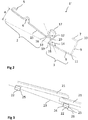
- Fig. 1 shows a schematic drawing of a first preferred embodiment of the invention in perspective view.
- Fig. 1 is a storm spring 1 for connecting a roof tile 21 with a roof batten 22 such as from Fig. 3 seen.
- the storm spring 1 has a holding device 2 for connecting the storm spring 1 with the roof tile 21, a clamping device 3 for connecting the storm spring 1 with the roof batten 22 and a leg spring 4.
- the holding device 2 is connected via the leg spring 4 with the clamping device 3 and the storm spring 1 can be clamped by means of the clamping device 3 to the roof batten 22.
- a torque in the holding device 2 can be introduced, so that the roof tile 21 via the holding device 2 is resiliently pressed against the roof batten 22.
- Fig. 2 shows a schematic drawing of a second embodiment of the invention in a perspective view.
- the holding device 2 has an engagement 5 for holding the roof tile 21.
- the engagement device 6 and the engagement 5 of the holding device 2 are configured such that the engagement 5 of the holding device 2 of a first storm spring 1, 1 'is suitable for insertion into the engagement device 6 of the holding device 2 of a second storm spring 1'.
- the engagement device 6 is designed in the form of a V.
- leg spring 4 is made of a shaped spring wire in the form of a winding 17 and with a first and a second spring leg 12, 13 executed.
- the clamping device 3 is made of a shaped spring wire in the form of a U with two longitudinal legs 7, 8 and a transverse leg 9. It is suitable for laterally enclosing a roof batten 22, wherein the first longitudinal leg 7 is designed to be shorter than the second longitudinal leg 8.
- the angle 10 between the first longitudinal leg 7 and transverse leg 9 has a value of 88 °.
- the angle 11 between transverse leg 9 and second longitudinal leg 8 is 95 °.
- the first of the spring leg 12 is connected to the second longitudinal leg 8 of the clamping device 3 via the portion 19 and the angle 18 and 20 such that the angle 14 between the second longitudinal leg 8 and the first spring leg 12 has a value of 137 °.
- the value of the angle 14 is fundamentally dependent on the number of turns, the radius and the winding direction of the winding 17, so that it is to be adapted as a function of a change in the dimensioning of said parameters.
- the winding 17 is designed to be closed and has 1.75 turns.
- the length of the second longitudinal leg 8 and the transverse leg 7 are dependent on the dimension of the roof batten 22.
- the holding device 2 has a holding arm 15 with an engagement 5 for holding a roof tile 21.
- the leg spring 4 is connected via the second of the spring leg 13 with the support arm 15 of the holding device 2 at a compensation angle 16 such that during assembly of the storm spring 1 in an arrangement of a roof pan 21 and a roof batten 22 a deflection angle ⁇ between the support arm 15 and the second longitudinal leg 8, and the lower longitudinal side 26 of the roof batten 22 is in a range between 15 ° and 75 °. Due to a bias, which may be, for example, 45 °, has the Fig. 2 apparent deflection angle ⁇ has a value of 11 °.
- Fig. 3 shows a schematic drawing of a conventional arrangement of roof tiles 21 and battens 22nd
- the roof battens 22 a roof surface 23 spanned.
- the roof battens 22 have a rectangular cross section with an upper transverse side 24, a lower transverse side 25 and a lower longitudinal side 26.
- the roof tiles 21 are overlapping on the roof battens 22, wherein a roof pan 21 has a nose which presses against the upper half of the upper transverse side 24 of a roof batten 22 and secures them against slipping.
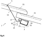
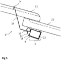
- Fig. 4 shows a schematic drawing of the storm spring 1 mounted in a conventional arrangement of roof tiles 21 and battens 22nd
- leg spring 4 is connected to the clamping device 3 such that in the connection of the clamping device 3 with the roof batten 22, the winding 17 of the leg spring 4 is arranged laterally in front of a transverse side of the roof batten 22.
- the storm spring 1 is pressed against a transverse side of the roof batten 22 due to a tension of the leg spring 4 with the winding 17 of the leg spring 4.
- the pressure is applied in the upper half of the upper transverse side 24 of the batten 22nd
- the angle 14 is designed as a 90 ° angle, so that the first spring leg 12 rests on a mounting on the upper transverse side 24 of the roof batten 22.
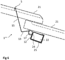
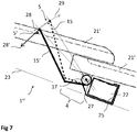
- Fig. 7 shows a schematic drawing of the effect of the storm spring 1 "mounted in a conventional arrangement of roof tiles 21 and battens 22nd
- the Fig. 7 equals to Fig. 5 with the difference that the roof tiles 21 'in Fig. 7 have a lower height.
- the winding 17 has an axis of rotation 27, so that the engagement 5 is movable along an arc 29.
- the radius of the arc 29 corresponds to the effective support arm of the stormspring 1 ".
- the holding arm 15 ' is opposite to the position of the holding arm 15 in FIG Fig. 5 shown rotated in the counterclockwise direction.
- the leg spring 4 in Fig. 7 opposite to the situation in Fig. 5 partially relaxed.
- a force 28' acting in a position of the support arm 15 ', a force 28', which is less than the force 28 in a position of the support arm 15.
- the direction of the forces acting tangentially along the arc 29 forces 28 and 28 ' so that each in the direction of the roof surface 23 acting force component remains approximately constant.
- FIG. 8 shows a schematic drawing of a fifth embodiment of the invention in a plan view, corresponding to a view of the storm spring 1 "" in the installed, unstressed state from a viewing direction against the normal of the roof surface 23rd
- FIG. 8 a Sturmfeder 1 "" with a holding device 2 can be seen, wherein the holding device 2 has a holding arm 15 and an engagement 5 for holding a roof tile 21, 21 ', and wherein the holding arm 15 in its upper half has a tilt angle 30 with an amount ⁇ by which a tilting region 31 is deflected above the position of the tilting angle 30 in the direction 32 of a roof tile 21, 21 'to be held
- the holding arm 15 is made by a spring wire.
- the Sturmfeder 1 "" is shown unstrung in a mounting position.
- the tilt angle ⁇ is in two
- Kippwinkelanteile ⁇ 1 and ⁇ 2 decomposable of which the first Kippwinkelanteil ⁇ 1 is a deflection of the support arm 15 in the direction 32 of a roof tile 21, 21 ', that is parallel to the roof surface 23 and parallel to the longitudinal axis of a roof batten 22, and the second Kippwinkelanteil ⁇ 2, a deflection of the support arm 15 transversely to this direction 32, that is, not shown here from the drawing plane, causes.
- the first Kippwinkelanteil ⁇ 1 is designed as a relatively shallow angle with a value of about 5 degrees.
- the tilting portion 31 of the holding arm 15 has a length of about 15 mm.
- the upper end of the tilting portion 31 is in the engagement 5, which has a hook in the form of a downwardly open bow.
- FIG. 8 Furthermore, a clamping device 3 can be seen wherein the, the clamping device 2 out of the plane of the drawing out U-shaped and is adapted to be laterally pushed onto a transverse side of a rectangular roof batten 22.
- the storm spring 1 "" has an abutment in the form of the winding 17 of a leg spring 4, through which the storm spring 1 "" a batten 22 on the side not enclosed by the clamping device 3 can be pressed.
- the storm spring 1 "" is completely executed by a spring wire and contactable via one contact point 33, 34, 35, 36, each with a side of a rectangular roof batten 22.
- One of the contact points 33, 34, 35, 36 namely contact point 33, points to a parallel to the roof batten 22 aligned coordinate axis, that is, along one of the direction 32 aligned coordinate axis, opposite two of the other contact points 34, 35, 36, for example, the contact points 34 and 35, a negative offset.
- the clamping device 3 is designed such that the first longitudinal leg 7 of the U-shaped clamping device 3 spans a surface 37 for partial support on the upper longitudinal side of a roof batten 22.
- the surface 37 is oriented on the first longitudinal limb 7 such that it comes to lie approximately parallel to the upper longitudinal side of a roof lath 22 in the mounted state of the storm spring 1 "".
- the surface 37 is realized by an additional lateral bending of a spring wire end of the clamping device 3 in the form of a triangle. Furthermore, the surface 37 is formed to have a curve in the direction of the opening of the U-shape. In addition, the profile of the surface 37 at its edge has a rounding, since it is formed by a curved wire with a round profile. By a further bend, the surface 37 is almost closed. A remaining opening 38 corresponds approximately to the strength of the spring wire.
- FIG. 9 shows a schematic drawing of the fifth embodiment of the invention in a perspective view, from which the position of the contact points 33. 34, 35, 36 is better visible.
- the angle 10 between the surface 37 and the transverse leg 9 has an amount of 88 degrees.
Landscapes
- Engineering & Computer Science (AREA)
- Mechanical Engineering (AREA)
- Architecture (AREA)
- Civil Engineering (AREA)
- Structural Engineering (AREA)
- Building Environments (AREA)
Priority Applications (1)
| Application Number | Priority Date | Filing Date | Title |
|---|---|---|---|
| PL17199101T PL3318691T3 (pl) | 2016-11-02 | 2017-10-30 | Sprężyna burzowa |
Applications Claiming Priority (2)
| Application Number | Priority Date | Filing Date | Title |
|---|---|---|---|
| DE102016120896.5A DE102016120896A1 (de) | 2016-11-02 | 2016-11-02 | Sturmfeder |
| DE102017120331.1A DE102017120331A1 (de) | 2016-11-02 | 2017-09-04 | Sturmfeder |
Publications (2)
| Publication Number | Publication Date |
|---|---|
| EP3318691A1 true EP3318691A1 (fr) | 2018-05-09 |
| EP3318691B1 EP3318691B1 (fr) | 2019-11-27 |
Family
ID=60201380
Family Applications (1)
| Application Number | Title | Priority Date | Filing Date |
|---|---|---|---|
| EP17199101.1A Active EP3318691B1 (fr) | 2016-11-02 | 2017-10-30 | Ressort de tempête |
Country Status (2)
| Country | Link |
|---|---|
| EP (1) | EP3318691B1 (fr) |
| PL (1) | PL3318691T3 (fr) |
Citations (5)
| Publication number | Priority date | Publication date | Assignee | Title |
|---|---|---|---|---|
| FR634547A (fr) * | 1927-05-18 | 1928-02-20 | Système de fixation de tuiles | |
| FR660305A (fr) * | 1928-09-13 | 1929-07-10 | Agrafe métallique pour tuiles de toits | |
| DE8506048U1 (de) * | 1985-03-02 | 1985-05-09 | Ossenberg-Schule + Söhne KG, 5990 Altena | Sturmklammer |
| DE202008015113U1 (de) * | 2008-11-14 | 2009-02-19 | Friedrich Ossenberg-Schule & Söhne GmbH & Co. KG | Klammer aus Draht zur Befestigung und Sicherung von Dacheindeckungsplatten |
| FR3022571A1 (fr) * | 2014-06-18 | 2015-12-25 | Frenehard & Michaux Sa | Crochet pour la fixation de tuiles a emboitement montees a recouvrement sur des liteaux de toiture d'un batiment |
-
2017
- 2017-10-30 PL PL17199101T patent/PL3318691T3/pl unknown
- 2017-10-30 EP EP17199101.1A patent/EP3318691B1/fr active Active
Patent Citations (5)
| Publication number | Priority date | Publication date | Assignee | Title |
|---|---|---|---|---|
| FR634547A (fr) * | 1927-05-18 | 1928-02-20 | Système de fixation de tuiles | |
| FR660305A (fr) * | 1928-09-13 | 1929-07-10 | Agrafe métallique pour tuiles de toits | |
| DE8506048U1 (de) * | 1985-03-02 | 1985-05-09 | Ossenberg-Schule + Söhne KG, 5990 Altena | Sturmklammer |
| DE202008015113U1 (de) * | 2008-11-14 | 2009-02-19 | Friedrich Ossenberg-Schule & Söhne GmbH & Co. KG | Klammer aus Draht zur Befestigung und Sicherung von Dacheindeckungsplatten |
| FR3022571A1 (fr) * | 2014-06-18 | 2015-12-25 | Frenehard & Michaux Sa | Crochet pour la fixation de tuiles a emboitement montees a recouvrement sur des liteaux de toiture d'un batiment |
Also Published As
| Publication number | Publication date |
|---|---|
| EP3318691B1 (fr) | 2019-11-27 |
| PL3318691T3 (pl) | 2020-04-30 |
Similar Documents
| Publication | Publication Date | Title |
|---|---|---|
| DE102018126856B4 (de) | Vorrichtung zur Befestigung von flexiblen Geweben für den Innen- und Außenbereich in der Architektur | |
| EP2186963A1 (fr) | Pince en fil d'acier destinée à la fixation et la sécurisation de plaques de recouvrement de toit | |
| EP1462585B1 (fr) | Crochet de retenue de tuile | |
| DE3509077A1 (de) | Klammer zur befestigung von dacheindeckungselementen | |
| EP3318691B1 (fr) | Ressort de tempête | |
| DE102017120331A1 (de) | Sturmfeder | |
| DE102016120896A1 (de) | Sturmfeder | |
| EP3779098B1 (fr) | Étrier de retenue pour matières de construction, ainsi que revêtement mural et procédé de fixation des éléments de revêtement mural | |
| DE68914009T2 (de) | Befestigungsvorrichtung für Dachziegel. | |
| DE4310420C1 (de) | Vorrichtung zur Befestigung von Firstabdeckungen am Dachfirst einer Dacheindeckung | |
| DE3941216A1 (de) | Firstziegelhalterung | |
| EP1811101A2 (fr) | Crochet de retenue | |
| EP2685022A1 (fr) | Module de sécurisation du windsog pour éléments monoplans | |
| DE102008016028A1 (de) | Firstziegelhalterung | |
| DE202010009958U1 (de) | Anordnung zum Eindecken eines Gebäudedaches | |
| DE202008015115U1 (de) | Vorrichtung zur Befestigung und Lagesicherung von Dacheindeckungsplatten auf einer Dachunterkonstruktion | |
| DE102009007352B4 (de) | Vorrichtung zum Eindecken einer Unterkonstruktion | |
| DE202004007940U1 (de) | Halterung für einen Blumenkasten | |
| EP3266953A1 (fr) | Dispositif de fixation et/ou de stabilisation d'une poutre faîtière | |
| DE7046013U (de) | Vorrichtung zum Halten von Dachrinnen | |
| DE202022106233U1 (de) | Fassadenrinne | |
| DE2707484C2 (fr) | ||
| EP4560104A1 (fr) | Dispositif de montage d'un dispositif de réception pour au moins un moyen de fixation d'une fixation de rebord de fenêtre dans un mur ainsi que module correspondant | |
| DE202025000838U1 (de) | Klemmhalterung, Montageschiene und Montagesystem für plattenförmige Bauteile | |
| DE3129483C2 (de) | Montagehilfsvorrichtung zum Befestigen von Dämmstoffbahnen |
Legal Events
| Date | Code | Title | Description |
|---|---|---|---|
| PUAI | Public reference made under article 153(3) epc to a published international application that has entered the european phase |
Free format text: ORIGINAL CODE: 0009012 |
|
| STAA | Information on the status of an ep patent application or granted ep patent |
Free format text: STATUS: THE APPLICATION HAS BEEN PUBLISHED |
|
| AK | Designated contracting states |
Kind code of ref document: A1 Designated state(s): AL AT BE BG CH CY CZ DE DK EE ES FI FR GB GR HR HU IE IS IT LI LT LU LV MC MK MT NL NO PL PT RO RS SE SI SK SM TR |
|
| AX | Request for extension of the european patent |
Extension state: BA ME |
|
| STAA | Information on the status of an ep patent application or granted ep patent |
Free format text: STATUS: REQUEST FOR EXAMINATION WAS MADE |
|
| RBV | Designated contracting states (corrected) |
Designated state(s): AL AT BE BG CH CY CZ DE DK EE ES FI FR GB GR HR HU IE IS IT LI LT LU LV MC MK MT NL NO PL PT RO RS SE SI SK SM TR |
|
| 17P | Request for examination filed |
Effective date: 20181112 |
|
| GRAP | Despatch of communication of intention to grant a patent |
Free format text: ORIGINAL CODE: EPIDOSNIGR1 |
|
| STAA | Information on the status of an ep patent application or granted ep patent |
Free format text: STATUS: GRANT OF PATENT IS INTENDED |
|
| INTG | Intention to grant announced |
Effective date: 20190522 |
|
| GRAS | Grant fee paid |
Free format text: ORIGINAL CODE: EPIDOSNIGR3 |
|
| GRAJ | Information related to disapproval of communication of intention to grant by the applicant or resumption of examination proceedings by the epo deleted |
Free format text: ORIGINAL CODE: EPIDOSDIGR1 |
|
| GRAL | Information related to payment of fee for publishing/printing deleted |
Free format text: ORIGINAL CODE: EPIDOSDIGR3 |
|
| STAA | Information on the status of an ep patent application or granted ep patent |
Free format text: STATUS: REQUEST FOR EXAMINATION WAS MADE |
|
| GRAR | Information related to intention to grant a patent recorded |
Free format text: ORIGINAL CODE: EPIDOSNIGR71 |
|
| STAA | Information on the status of an ep patent application or granted ep patent |
Free format text: STATUS: GRANT OF PATENT IS INTENDED |
|
| INTC | Intention to grant announced (deleted) | ||
| INTG | Intention to grant announced |
Effective date: 20190918 |
|
| GRAA | (expected) grant |
Free format text: ORIGINAL CODE: 0009210 |
|
| STAA | Information on the status of an ep patent application or granted ep patent |
Free format text: STATUS: THE PATENT HAS BEEN GRANTED |
|
| AK | Designated contracting states |
Kind code of ref document: B1 Designated state(s): AL AT BE BG CH CY CZ DE DK EE ES FI FR GB GR HR HU IE IS IT LI LT LU LV MC MK MT NL NO PL PT RO RS SE SI SK SM TR |
|
| REG | Reference to a national code |
Ref country code: GB Ref legal event code: FG4D Free format text: NOT ENGLISH |
|
| REG | Reference to a national code |
Ref country code: CH Ref legal event code: EP |
|
| REG | Reference to a national code |
Ref country code: AT Ref legal event code: REF Ref document number: 1206812 Country of ref document: AT Kind code of ref document: T Effective date: 20191215 |
|
| REG | Reference to a national code |
Ref country code: DE Ref legal event code: R096 Ref document number: 502017002989 Country of ref document: DE |
|
| REG | Reference to a national code |
Ref country code: IE Ref legal event code: FG4D Free format text: LANGUAGE OF EP DOCUMENT: GERMAN |
|
| REG | Reference to a national code |
Ref country code: CH Ref legal event code: NV Representative=s name: TR-IP CONSULTING LLC, CH |
|
| REG | Reference to a national code |
Ref country code: NL Ref legal event code: FP |
|
| REG | Reference to a national code |
Ref country code: LT Ref legal event code: MG4D |
|
| PG25 | Lapsed in a contracting state [announced via postgrant information from national office to epo] |
Ref country code: LT Free format text: LAPSE BECAUSE OF FAILURE TO SUBMIT A TRANSLATION OF THE DESCRIPTION OR TO PAY THE FEE WITHIN THE PRESCRIBED TIME-LIMIT Effective date: 20191127 Ref country code: NO Free format text: LAPSE BECAUSE OF FAILURE TO SUBMIT A TRANSLATION OF THE DESCRIPTION OR TO PAY THE FEE WITHIN THE PRESCRIBED TIME-LIMIT Effective date: 20200227 Ref country code: GR Free format text: LAPSE BECAUSE OF FAILURE TO SUBMIT A TRANSLATION OF THE DESCRIPTION OR TO PAY THE FEE WITHIN THE PRESCRIBED TIME-LIMIT Effective date: 20200228 Ref country code: BG Free format text: LAPSE BECAUSE OF FAILURE TO SUBMIT A TRANSLATION OF THE DESCRIPTION OR TO PAY THE FEE WITHIN THE PRESCRIBED TIME-LIMIT Effective date: 20200227 Ref country code: SE Free format text: LAPSE BECAUSE OF FAILURE TO SUBMIT A TRANSLATION OF THE DESCRIPTION OR TO PAY THE FEE WITHIN THE PRESCRIBED TIME-LIMIT Effective date: 20191127 Ref country code: LV Free format text: LAPSE BECAUSE OF FAILURE TO SUBMIT A TRANSLATION OF THE DESCRIPTION OR TO PAY THE FEE WITHIN THE PRESCRIBED TIME-LIMIT Effective date: 20191127 Ref country code: FI Free format text: LAPSE BECAUSE OF FAILURE TO SUBMIT A TRANSLATION OF THE DESCRIPTION OR TO PAY THE FEE WITHIN THE PRESCRIBED TIME-LIMIT Effective date: 20191127 |
|
| PG25 | Lapsed in a contracting state [announced via postgrant information from national office to epo] |
Ref country code: RS Free format text: LAPSE BECAUSE OF FAILURE TO SUBMIT A TRANSLATION OF THE DESCRIPTION OR TO PAY THE FEE WITHIN THE PRESCRIBED TIME-LIMIT Effective date: 20191127 Ref country code: IS Free format text: LAPSE BECAUSE OF FAILURE TO SUBMIT A TRANSLATION OF THE DESCRIPTION OR TO PAY THE FEE WITHIN THE PRESCRIBED TIME-LIMIT Effective date: 20200327 Ref country code: HR Free format text: LAPSE BECAUSE OF FAILURE TO SUBMIT A TRANSLATION OF THE DESCRIPTION OR TO PAY THE FEE WITHIN THE PRESCRIBED TIME-LIMIT Effective date: 20191127 |
|
| PG25 | Lapsed in a contracting state [announced via postgrant information from national office to epo] |
Ref country code: AL Free format text: LAPSE BECAUSE OF FAILURE TO SUBMIT A TRANSLATION OF THE DESCRIPTION OR TO PAY THE FEE WITHIN THE PRESCRIBED TIME-LIMIT Effective date: 20191127 |
|
| PG25 | Lapsed in a contracting state [announced via postgrant information from national office to epo] |
Ref country code: ES Free format text: LAPSE BECAUSE OF FAILURE TO SUBMIT A TRANSLATION OF THE DESCRIPTION OR TO PAY THE FEE WITHIN THE PRESCRIBED TIME-LIMIT Effective date: 20191127 Ref country code: DK Free format text: LAPSE BECAUSE OF FAILURE TO SUBMIT A TRANSLATION OF THE DESCRIPTION OR TO PAY THE FEE WITHIN THE PRESCRIBED TIME-LIMIT Effective date: 20191127 Ref country code: EE Free format text: LAPSE BECAUSE OF FAILURE TO SUBMIT A TRANSLATION OF THE DESCRIPTION OR TO PAY THE FEE WITHIN THE PRESCRIBED TIME-LIMIT Effective date: 20191127 Ref country code: CZ Free format text: LAPSE BECAUSE OF FAILURE TO SUBMIT A TRANSLATION OF THE DESCRIPTION OR TO PAY THE FEE WITHIN THE PRESCRIBED TIME-LIMIT Effective date: 20191127 Ref country code: PT Free format text: LAPSE BECAUSE OF FAILURE TO SUBMIT A TRANSLATION OF THE DESCRIPTION OR TO PAY THE FEE WITHIN THE PRESCRIBED TIME-LIMIT Effective date: 20200419 Ref country code: RO Free format text: LAPSE BECAUSE OF FAILURE TO SUBMIT A TRANSLATION OF THE DESCRIPTION OR TO PAY THE FEE WITHIN THE PRESCRIBED TIME-LIMIT Effective date: 20191127 |
|
| REG | Reference to a national code |
Ref country code: DE Ref legal event code: R097 Ref document number: 502017002989 Country of ref document: DE |
|
| PG25 | Lapsed in a contracting state [announced via postgrant information from national office to epo] |
Ref country code: SM Free format text: LAPSE BECAUSE OF FAILURE TO SUBMIT A TRANSLATION OF THE DESCRIPTION OR TO PAY THE FEE WITHIN THE PRESCRIBED TIME-LIMIT Effective date: 20191127 Ref country code: SK Free format text: LAPSE BECAUSE OF FAILURE TO SUBMIT A TRANSLATION OF THE DESCRIPTION OR TO PAY THE FEE WITHIN THE PRESCRIBED TIME-LIMIT Effective date: 20191127 |
|
| PLBE | No opposition filed within time limit |
Free format text: ORIGINAL CODE: 0009261 |
|
| STAA | Information on the status of an ep patent application or granted ep patent |
Free format text: STATUS: NO OPPOSITION FILED WITHIN TIME LIMIT |
|
| 26N | No opposition filed |
Effective date: 20200828 |
|
| PG25 | Lapsed in a contracting state [announced via postgrant information from national office to epo] |
Ref country code: SI Free format text: LAPSE BECAUSE OF FAILURE TO SUBMIT A TRANSLATION OF THE DESCRIPTION OR TO PAY THE FEE WITHIN THE PRESCRIBED TIME-LIMIT Effective date: 20191127 |
|
| PG25 | Lapsed in a contracting state [announced via postgrant information from national office to epo] |
Ref country code: IT Free format text: LAPSE BECAUSE OF FAILURE TO SUBMIT A TRANSLATION OF THE DESCRIPTION OR TO PAY THE FEE WITHIN THE PRESCRIBED TIME-LIMIT Effective date: 20191127 |
|
| PG25 | Lapsed in a contracting state [announced via postgrant information from national office to epo] |
Ref country code: LU Free format text: LAPSE BECAUSE OF NON-PAYMENT OF DUE FEES Effective date: 20201030 Ref country code: MC Free format text: LAPSE BECAUSE OF FAILURE TO SUBMIT A TRANSLATION OF THE DESCRIPTION OR TO PAY THE FEE WITHIN THE PRESCRIBED TIME-LIMIT Effective date: 20191127 |
|
| PG25 | Lapsed in a contracting state [announced via postgrant information from national office to epo] |
Ref country code: IE Free format text: LAPSE BECAUSE OF NON-PAYMENT OF DUE FEES Effective date: 20201030 |
|
| PGFP | Annual fee paid to national office [announced via postgrant information from national office to epo] |
Ref country code: NL Payment date: 20211011 Year of fee payment: 5 |
|
| PGFP | Annual fee paid to national office [announced via postgrant information from national office to epo] |
Ref country code: FR Payment date: 20211006 Year of fee payment: 5 Ref country code: CH Payment date: 20211013 Year of fee payment: 5 Ref country code: BE Payment date: 20211011 Year of fee payment: 5 |
|
| PGFP | Annual fee paid to national office [announced via postgrant information from national office to epo] |
Ref country code: PL Payment date: 20211015 Year of fee payment: 5 |
|
| PG25 | Lapsed in a contracting state [announced via postgrant information from national office to epo] |
Ref country code: TR Free format text: LAPSE BECAUSE OF FAILURE TO SUBMIT A TRANSLATION OF THE DESCRIPTION OR TO PAY THE FEE WITHIN THE PRESCRIBED TIME-LIMIT Effective date: 20191127 Ref country code: MT Free format text: LAPSE BECAUSE OF FAILURE TO SUBMIT A TRANSLATION OF THE DESCRIPTION OR TO PAY THE FEE WITHIN THE PRESCRIBED TIME-LIMIT Effective date: 20191127 Ref country code: CY Free format text: LAPSE BECAUSE OF FAILURE TO SUBMIT A TRANSLATION OF THE DESCRIPTION OR TO PAY THE FEE WITHIN THE PRESCRIBED TIME-LIMIT Effective date: 20191127 |
|
| GBPC | Gb: european patent ceased through non-payment of renewal fee |
Effective date: 20211030 |
|
| PG25 | Lapsed in a contracting state [announced via postgrant information from national office to epo] |
Ref country code: MK Free format text: LAPSE BECAUSE OF FAILURE TO SUBMIT A TRANSLATION OF THE DESCRIPTION OR TO PAY THE FEE WITHIN THE PRESCRIBED TIME-LIMIT Effective date: 20191127 |
|
| PG25 | Lapsed in a contracting state [announced via postgrant information from national office to epo] |
Ref country code: GB Free format text: LAPSE BECAUSE OF NON-PAYMENT OF DUE FEES Effective date: 20211030 |
|
| REG | Reference to a national code |
Ref country code: CH Ref legal event code: PL |
|
| REG | Reference to a national code |
Ref country code: NL Ref legal event code: MM Effective date: 20221101 |
|
| REG | Reference to a national code |
Ref country code: BE Ref legal event code: MM Effective date: 20221031 |
|
| PG25 | Lapsed in a contracting state [announced via postgrant information from national office to epo] |
Ref country code: NL Free format text: LAPSE BECAUSE OF NON-PAYMENT OF DUE FEES Effective date: 20221101 Ref country code: LI Free format text: LAPSE BECAUSE OF NON-PAYMENT OF DUE FEES Effective date: 20221031 Ref country code: FR Free format text: LAPSE BECAUSE OF NON-PAYMENT OF DUE FEES Effective date: 20221031 Ref country code: CH Free format text: LAPSE BECAUSE OF NON-PAYMENT OF DUE FEES Effective date: 20221031 |
|
| PG25 | Lapsed in a contracting state [announced via postgrant information from national office to epo] |
Ref country code: BE Free format text: LAPSE BECAUSE OF NON-PAYMENT OF DUE FEES Effective date: 20221031 |
|
| REG | Reference to a national code |
Ref country code: AT Ref legal event code: MM01 Ref document number: 1206812 Country of ref document: AT Kind code of ref document: T Effective date: 20221030 |
|
| PG25 | Lapsed in a contracting state [announced via postgrant information from national office to epo] |
Ref country code: AT Free format text: LAPSE BECAUSE OF NON-PAYMENT OF DUE FEES Effective date: 20221030 |
|
| PG25 | Lapsed in a contracting state [announced via postgrant information from national office to epo] |
Ref country code: PL Free format text: LAPSE BECAUSE OF NON-PAYMENT OF DUE FEES Effective date: 20221030 |
|
| PGFP | Annual fee paid to national office [announced via postgrant information from national office to epo] |
Ref country code: DE Payment date: 20241028 Year of fee payment: 8 |