EP3318764B1 - Pompe à vide avec protection contre un excès de vitesse - Google Patents
Pompe à vide avec protection contre un excès de vitesse Download PDFInfo
- Publication number
- EP3318764B1 EP3318764B1 EP17207279.5A EP17207279A EP3318764B1 EP 3318764 B1 EP3318764 B1 EP 3318764B1 EP 17207279 A EP17207279 A EP 17207279A EP 3318764 B1 EP3318764 B1 EP 3318764B1
- Authority
- EP
- European Patent Office
- Prior art keywords
- vacuum pump
- microcontroller
- drive
- pump system
- phases
- Prior art date
- Legal status (The legal status is an assumption and is not a legal conclusion. Google has not performed a legal analysis and makes no representation as to the accuracy of the status listed.)
- Active
Links
Images
Classifications
-
- F—MECHANICAL ENGINEERING; LIGHTING; HEATING; WEAPONS; BLASTING
- F04—POSITIVE - DISPLACEMENT MACHINES FOR LIQUIDS; PUMPS FOR LIQUIDS OR ELASTIC FLUIDS
- F04D—NON-POSITIVE-DISPLACEMENT PUMPS
- F04D19/00—Axial-flow pumps
- F04D19/02—Multi-stage pumps
- F04D19/04—Multi-stage pumps specially adapted to the production of a high vacuum, e.g. molecular pumps
-
- F—MECHANICAL ENGINEERING; LIGHTING; HEATING; WEAPONS; BLASTING
- F04—POSITIVE - DISPLACEMENT MACHINES FOR LIQUIDS; PUMPS FOR LIQUIDS OR ELASTIC FLUIDS
- F04D—NON-POSITIVE-DISPLACEMENT PUMPS
- F04D25/00—Pumping installations or systems
- F04D25/02—Units comprising pumps and their driving means
- F04D25/06—Units comprising pumps and their driving means the pump being electrically driven
-
- F—MECHANICAL ENGINEERING; LIGHTING; HEATING; WEAPONS; BLASTING
- F04—POSITIVE - DISPLACEMENT MACHINES FOR LIQUIDS; PUMPS FOR LIQUIDS OR ELASTIC FLUIDS
- F04D—NON-POSITIVE-DISPLACEMENT PUMPS
- F04D27/00—Control, e.g. regulation, of pumps, pumping installations or pumping systems specially adapted for elastic fluids
- F04D27/001—Testing thereof; Determination or simulation of flow characteristics; Stall or surge detection, e.g. condition monitoring
-
- F—MECHANICAL ENGINEERING; LIGHTING; HEATING; WEAPONS; BLASTING
- F04—POSITIVE - DISPLACEMENT MACHINES FOR LIQUIDS; PUMPS FOR LIQUIDS OR ELASTIC FLUIDS
- F04D—NON-POSITIVE-DISPLACEMENT PUMPS
- F04D27/00—Control, e.g. regulation, of pumps, pumping installations or pumping systems specially adapted for elastic fluids
- F04D27/02—Surge control
- F04D27/0261—Surge control by varying driving speed
-
- F—MECHANICAL ENGINEERING; LIGHTING; HEATING; WEAPONS; BLASTING
- F04—POSITIVE - DISPLACEMENT MACHINES FOR LIQUIDS; PUMPS FOR LIQUIDS OR ELASTIC FLUIDS
- F04D—NON-POSITIVE-DISPLACEMENT PUMPS
- F04D27/00—Control, e.g. regulation, of pumps, pumping installations or pumping systems specially adapted for elastic fluids
- F04D27/02—Surge control
- F04D27/0292—Stop safety or alarm devices, e.g. stop-and-go control; Disposition of check-valves
-
- F—MECHANICAL ENGINEERING; LIGHTING; HEATING; WEAPONS; BLASTING
- F05—INDEXING SCHEMES RELATING TO ENGINES OR PUMPS IN VARIOUS SUBCLASSES OF CLASSES F01-F04
- F05D—INDEXING SCHEME FOR ASPECTS RELATING TO NON-POSITIVE-DISPLACEMENT MACHINES OR ENGINES, GAS-TURBINES OR JET-PROPULSION PLANTS
- F05D2260/00—Function
- F05D2260/84—Redundancy
-
- Y—GENERAL TAGGING OF NEW TECHNOLOGICAL DEVELOPMENTS; GENERAL TAGGING OF CROSS-SECTIONAL TECHNOLOGIES SPANNING OVER SEVERAL SECTIONS OF THE IPC; TECHNICAL SUBJECTS COVERED BY FORMER USPC CROSS-REFERENCE ART COLLECTIONS [XRACs] AND DIGESTS
- Y02—TECHNOLOGIES OR APPLICATIONS FOR MITIGATION OR ADAPTATION AGAINST CLIMATE CHANGE
- Y02B—CLIMATE CHANGE MITIGATION TECHNOLOGIES RELATED TO BUILDINGS, e.g. HOUSING, HOUSE APPLIANCES OR RELATED END-USER APPLICATIONS
- Y02B30/00—Energy efficient heating, ventilation or air conditioning [HVAC]
- Y02B30/70—Efficient control or regulation technologies, e.g. for control of refrigerant flow, motor or heating
Definitions
- the invention relates to a vacuum pump system according to the preamble of the first claim.
- the DE-OS 102 15 896 therefore proposes, in addition to a microcontroller, which takes over the direct control of the engine electronics, to provide a second microcontroller arranged in the vacuum pump which, among other things, monitors the first microcontroller.
- the disadvantage of this solution is that a large number of components are required on and in the vacuum pump.
- the arrangement of highly integrated electronic components on the pump itself can in some Applications may not be permitted, for example in environments with a high intensity of radiation.
- both microcontrollers are dependent on only one speed sensor, which indicates the rotation of the rotor, which limits the safety against malfunctions.
- the distribution of the electronics to the vacuum pump and control electronics can restrict the interchangeability of electronics and vacuum pump, ie vacuum pump and electronics cannot be combined as desired.
- the modes of operation (e.g. the underlying code) of the microcontrollers must be compared with one another. This is not user-friendly and creates unnecessary costs.
- the WO 03/085268 A1 discloses a vacuum pumping system according to the preamble of both claim 1 and claim 2. From the EP 1 311 047 A2 the measurement of a motor speed using voltages and currents is known. The EP 0 939 228 A1 relates to a drive control for a turbo molecular pump. Furthermore, the EP 1 211 774 A1 a control for a motor, in which the switching signals are checked. From the US 6 236 183 B1 Finally, sensorless detection of the rotation of electric motors is known.
- the object of the invention is to present a vacuum pump system in which the vacuum pump and control electronics can be freely combined and reliable overspeed protection is guaranteed.
- the vacuum pump system is based on a control unit and a vacuum pump, with a drive microcontroller in the control unit controlling an output stage and thus a brushless, multi-phase synchronous motor with permanent magnet excited rotor in rotation.
- This drive microcontroller switches off before an overspeed is reached.
- a second microcontroller is arranged within the control unit.
- Pump type recognition means are arranged in the vacuum pump and are evaluated by the control unit. In this way, the highest permissible speed for the vacuum pump is determined. A signal proportional to the rotor speed is fed to the second microcontroller. If it detects that the rotor is exceeding the maximum permissible speed, it also switches off the drive's output stage.
- the advantage of this arrangement is that there are only a few electrical and electronic components in the vacuum pump itself, essentially only the motor and the pump type detection means. In the simplest case, these are electrical resistors whose resistance value differs from pump type to pump type.
- the vacuum pump can also be used in environments in which the electronic components are exposed to high levels of exposure to radiation. Since the control electronics themselves determine the pump type, the vacuum pump and control electronics can be freely combined. Complex repairs to the vacuum pump in the event of damage to the control electronics are no longer necessary; the defective control electronics are replaced in their entirety. This saves service costs. This combinability also makes it possible to replace outdated control electronics with newer models, which is considerably more difficult in the prior art. Since a second microcontroller is arranged within the control electronics, which also monitors the speed and can switch off the output stage, there is reliable protection against exceeding the maximum permissible speed.
- the pump type identification means arranged in the vacuum pump are evaluated in the second microcontroller and the highest permissible speed for the vacuum pump is thus determined. He then communicates this to the drive microcontroller, for example via a serial data interface. This increases safety, since the determination of the maximum speed is decoupled from the actual drive train. It is an efficient design as no additional components are required.
- the drive microcontroller determines the speed of the motor from the motor model and the currents that are established in the phases. This inventive feature is based on the knowledge that a synchronous motor rotates at the most with the speed with which the magnetic field generated by the coil energization rotates. This means that both operation and protection against overspeed can be set up without sensors. This makes sensors on the vacuum pump superfluous, which further reduces the number of components.
- the second microcontroller determines the rotational frequency from a signal which is derived from the measurement of the voltages applied to the phases. Since the speed determination is derived from two different measurements, each microcontroller has its own speed signal, so that the security of the monitoring is increased. Overall, redundant monitoring can be set up that has two channels throughout, i.e. there is a second way for each part of the surveillance system.
- the measurement of the currents and voltages on the phases takes place at current and voltage measuring points within the control unit. This increases the ability of the control units to be combined with vacuum pumps and means that only the motor and pump type detection means have to be arranged in the vacuum pump for the drive. It also reduces the number of electrical connections that are necessary between the vacuum pump and the control unit.
- the invention can advantageously be further developed by also connecting the line via which the second microcontroller switches off the output stage to an input of the drive microcontroller.
- the drive microcontroller recognizes an operating state that is not permitted for it and can prepare for a controlled restart of the drive.
- Another feature of the invention relates to the measurement of the voltage in the phases. According to the invention, these voltages are converted to a part of the drive microcontroller with an analog-to-digital converter into a digital signal, which is then evaluated by the second microcontroller. In this way, additional converter components are avoided.
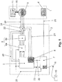
- FIG. 1 Simplified scheme of the vacuum pump system.
- FIG Figure 1 A simplified scheme of an exemplary vacuum pump system according to the invention is shown in FIG Figure 1 shown.
- the vacuum pump 1 has a motor 3. This is designed as a permanent magnet synchronous motor (PMSM), ie the rotor of the motor has permanent magnets that are surrounded by coils arranged on the motor stator, which generate a rotating magnetic field. The permanent magnets are magnetically coupled to this field so that the rotor is set in rotation.
- the rotor 10 is connected to the rotor shaft of the pump system 11 or is a part of it.
- the vacuum pump has pump type recognition means 4. These are electronic components, for example a memory chip is conceivable. These means are designed even more simply and thus less error-prone as simple electronic components such as electrical resistors.
- the different pump types differ, for example, in the power consumption of the drive, pumping speed and other vacuum-related data, maximum rotational frequency, moments of inertia of the rotor, etc.
- the control unit 2 is connected to the vacuum pump via lines 24 and 25. These lines are part of one or more cables.
- the control unit can be designed to be flange-mounted to the vacuum pump. In this case, the lines 24 and 25 can be replaced by a plug contact, so that no cable is necessary between the components.
- the drive microcontroller 5 and the output stage are arranged within the control unit, the output stage 6 being formed from the components output stage control 6a and power section 6b.
- the drive microcontroller controls the drive, i. it calculates the commutation to be carried out, ensures that the motor starts up from standstill to nominal speed, and controls the speed and current. To do this, he uses a motor model that describes the rotating system (rotor, shaft, drive) based on the physical data and simulates it within the drive microcontroller. Furthermore, it uses the measured currents, which are set in phases. These data are stored in a table in a memory, as they depend on the pump type, and are transferred to the drive controller after the pump type has been determined.
- the data can be stored in a second microcontroller, also located in the control unit, or in a separate memory. If the voltage supply of the vacuum pump system fails, the drive controller controls the generator operation of the motor to supply the control electronics.
- the output stage 6 has a multi-stage design, in the example with two stages which essentially amplify the signal from the low power levels of the drive microcontroller to the necessary high power levels of the motor. It is supplied with an intermediate circuit voltage from a power supply unit in a manner known per se (not shown here).
- the motor is three-phase.
- a current measurement is carried out on two of these phases, which is fed back to the drive controller via connection 20.
- the result of this measurement is combined compared with the voltages switched to the phases in the drive controller with the values that have been calculated with the motor model.
- the drive controller concludes from this comparison that the current speed is higher than is permitted for the pump type, it switches off the output stage.
- the current measurement is also used to set up a current control loop. This is necessary because the current flow in the coils determines the strength of the magnetic coupling between the coils and the rotor. On the one hand, this coupling must be strong enough to ensure safe rotation of the rotor even under loads; on the other hand, the current flow must be limited to a maximum value.
- the voltage is measured on all three phases and fed to a converter unit 8 in which the analog voltage signal is converted into a digital voltage signal.
- the converter unit is part of the drive controller 5, since in this way the same time base is used for the conversion as for the control of the output stage.
- the digitized signal is made available to the second microcontroller via a line 22.
- the signal can be transmitted over several parallel lines.
- this signal is a square wave signal with a frequency that corresponds to the current rotational frequency.
- this line can have two channels.
- the second controller 7 determines the rotational frequency from the digitized signal. For example, he can determine the number of square-wave pulses in a time interval.
- the second microcontroller evaluates the pump type recognition means 4 and takes from its memory the highest speed permitted for the recognized pump type. In order to achieve a two-channel system at this point, it is also advantageous for the pump user to enter this manually and compare the two values.
- a hand-held device 16, which has a Cable 15 is connected to the control electronics. The drive is only released for start and operation if they match.
- the current and voltage measurements are made at current measurement points 30 and voltage measurement points 31 within the control unit 2, which means that the control unit and vacuum pump can be exchanged to a high degree.
- no lines and / or plug connections have to be provided via which the measurement signals from the vacuum pump are fed into the control unit.
- only lines or plug connections for the drive phases and the pump type detection means need to be provided for operating the drive, which results in a considerable reduction in costs.
- With the motor model it is also possible to use sinusoidally energized motors within the vacuum pump without having to provide sensors. These motors have much more uniform running properties than, for example, block-cumulated motors, since there are no discontinuous changes in force vector. Overall, this creates a sensorless, redundant drive system.
- the microcontrollers are connected to one another via a serial data line. Control commands and status queries are carried out via these, and the second microcontroller also informs the drive microcontroller about the maximum speed that can be reached.
- the pump-specific data on which the motor model is based can also be transmitted via this channel. If the second controller 7 measures that the signal transmitted via the line 22 corresponds to a speed of the pump above the permissible value or the speed deviates to an impermissible extent from that transmitted via the serial connection 23, it switches off the output stage 6 via the line 26.
- this line is also connected to an input of the drive microcontroller, so that it switches off the output stage can determine. He can prepare a targeted restart that is adapted to the engine state (e.g. speed) at any rotor speed.
- Vacuum pump systems are often monitored from a central point, for which purpose electronic bus systems are used.
- components such as heating and cooling devices that have to be regulated. These tasks can be taken over by the second microcontroller.
Landscapes
- Engineering & Computer Science (AREA)
- Mechanical Engineering (AREA)
- General Engineering & Computer Science (AREA)
- Non-Positive Displacement Air Blowers (AREA)
- Control Of Positive-Displacement Pumps (AREA)
Claims (12)
- Système de pompe à vide comportant une pompe à vide (1), une unité de commande (2) et un second microcontrôleur surveillant la vitesse de rotation du moteur,
dans lequel
la pompe à vide comprend un moteur synchrone polyphasé (3) sans balais à rotor excité par aimant permanent,
l'unité de commande comprend un microcontrôleur d'entraînement (5) et un étage final (6a, 6b), et
le second microcontrôleur (7) est configuré pour couper l'étage final (6a, 6b) lors de la reconnaissance du dépassement d'une vitesse de rotation maximale,
caractérisé en ce que
le second microcontrôleur (7) est agencé dans l'unité de commande (2), la pompe à vide (1) comprend des moyens de reconnaissance de type de pompe (4), et
le microcontrôleur d'entraînement (5) est configuré pour définir la vitesse de rotation du moteur à partir d'un modèle de moteur et des courants qui s'établissent dans les phases,
une unité de conversion (8) pour convertir les tensions mesurées aux phases en un signal numérique étant agencée dans le microcontrôleur d'entraînement (5), et
le signal numérique étant évalué dans le second microcontrôleur (7). - Système de pompe à vide comportant une pompe à vide (1), une unité de commande (2) et un second microcontrôleur surveillant la vitesse de rotation du moteur,
dans lequel
la pompe à vide comprend un moteur synchrone polyphasé (3) sans balais à rotor excité par aimant permanent,
l'unité de commande comprend un microcontrôleur d'entraînement (5) et un étage final (6a, 6b), et
le second microcontrôleur (7) est configuré pour couper l'étage final (6a, 6b) lors de la reconnaissance du dépassement d'une vitesse de rotation maximale,
caractérisé en ce que
le second microcontrôleur (7) est agencé dans l'unité de commande (2), la pompe à vide (1) comprend des moyens de reconnaissance de type de pompe (4), et
le microcontrôleur d'entraînement (5) est configuré pour définir la vitesse de rotation à partir d'une partie des tensions appliquées aux phases et des courants qui s'établissent dans les phases,
une unité de conversion (8) pour convertir les tensions mesurées aux phases en un signal numérique étant agencée dans le microcontrôleur d'entraînement (5), et
le signal numérique étant évalué dans le second microcontrôleur (7). - Système de pompe à vide selon la revendication 1,
caractérisé en ce que
le microcontrôleur d'entraînement (5) est configuré pour définir la vitesse de rotation à partir d'une partie des tensions appliquées aux phases et des courants qui s'établissent dans les phases. - Système de pompe à vide selon la revendication 1, 2 ou 3,
caractérisé en ce que
le second microcontrôleur (7) est configuré pour évaluer les moyens de reconnaissance de type de pompe (4) agencés dans la pompe à vide (1) et pour déterminer ainsi la vitesse de rotation maximale admissible pour la pompe à vide. - Système de pompe à vide selon la revendication 2 ou 4,
caractérisé en ce que
le second microcontrôleur est configuré pour définir la vitesse de rotation à partir d'un signal qui est dérivé de la mesure des tensions appliquées aux phases. - Système de pompe à vide selon l'une des revendications précédentes,
caractérisé en ce que
des points de mesure de courant (30) et des points de mesure de tension (31) servant à définir la vitesse de rotation sont agencés à l'intérieur de l'unité de commande (2). - Système de pompe à vide selon l'une des revendications précédentes,
caractérisé en ce que
la ligne (26) servant à couper l'étage final présente une connexion à une entrée du microcontrôleur d'entraînement (5). - Système de pompe à vide selon l'une des revendications précédentes,
caractérisé en ce que
le microcontrôleur d'entraînement (5) est configuré pour couper avant d'atteindre une survitesse de rotation. - Système de pompe à vide selon l'une des revendications précédentes,
caractérisé en ce que
le microcontrôleur d'entraînement (5) est configuré pour commander un fonctionnement générateur du moteur pour alimenter une unité électronique de commande en cas de défaillance d'une alimentation en tension du système de pompe à vide. - Système de pompe à vide selon l'une des revendications précédentes,
caractérisé en ce que
le modèle de moteur décrit un système en rotation de la pompe à vide (1), le modèle de moteur étant simulé en particulier à l'intérieur du microcontrôleur d'entraînement (5). - Système de pompe à vide selon l'une des revendications précédentes,
caractérisé en ce que
un étage final (6) est agencé à l'intérieur de l'unité de commande (2), qui est réalisé de manière multi-étagée. - Système de pompe à vide selon l'une des revendications précédentes,
caractérisé en ce que
l'unité de conversion (8) est un composant du microcontrôleur d'entraînement (5), les tensions mesurées aux phases étant amenées à l'unité de conversion (8), l'unité de conversion (8) étant configurée pour convertir ce signal de tension analogique en un signal de tension numérique.
Applications Claiming Priority (2)
| Application Number | Priority Date | Filing Date | Title |
|---|---|---|---|
| DE102005045283.3A DE102005045283B4 (de) | 2005-09-22 | 2005-09-22 | Vakuumpumpsystem |
| EP06019123.6A EP1767790B1 (fr) | 2005-09-22 | 2006-09-13 | Système de pompe à vide |
Related Parent Applications (2)
| Application Number | Title | Priority Date | Filing Date |
|---|---|---|---|
| EP06019123.6A Division EP1767790B1 (fr) | 2005-09-22 | 2006-09-13 | Système de pompe à vide |
| EP06019123.6A Division-Into EP1767790B1 (fr) | 2005-09-22 | 2006-09-13 | Système de pompe à vide |
Publications (2)
| Publication Number | Publication Date |
|---|---|
| EP3318764A1 EP3318764A1 (fr) | 2018-05-09 |
| EP3318764B1 true EP3318764B1 (fr) | 2020-11-11 |
Family
ID=37607421
Family Applications (2)
| Application Number | Title | Priority Date | Filing Date |
|---|---|---|---|
| EP17207279.5A Active EP3318764B1 (fr) | 2005-09-22 | 2006-09-13 | Pompe à vide avec protection contre un excès de vitesse |
| EP06019123.6A Active EP1767790B1 (fr) | 2005-09-22 | 2006-09-13 | Système de pompe à vide |
Family Applications After (1)
| Application Number | Title | Priority Date | Filing Date |
|---|---|---|---|
| EP06019123.6A Active EP1767790B1 (fr) | 2005-09-22 | 2006-09-13 | Système de pompe à vide |
Country Status (4)
| Country | Link |
|---|---|
| US (1) | US8613600B2 (fr) |
| EP (2) | EP3318764B1 (fr) |
| JP (1) | JP2007085337A (fr) |
| DE (1) | DE102005045283B4 (fr) |
Families Citing this family (11)
| Publication number | Priority date | Publication date | Assignee | Title |
|---|---|---|---|---|
| ITMI20040941A1 (it) * | 2004-05-11 | 2005-11-12 | Plastedil Sa | Elemento costruttivo portante in particolare per la realizzazione di solai di edifici e struttura di solaio incorporante tale elemento |
| DE102008019451A1 (de) * | 2008-04-17 | 2009-10-22 | Oerlikon Leybold Vacuum Gmbh | Vakuumpumpe |
| FR2974412B1 (fr) * | 2011-04-21 | 2013-06-07 | Adixen Vacuum Products | Procede de controle d'un detecteur de fuites et detecteur de fuites |
| CN105889086A (zh) * | 2014-12-22 | 2016-08-24 | 张立民 | 利用传感器保证双动力内燃机动力协调输出的技术 |
| DE102016107928A1 (de) * | 2016-04-28 | 2017-11-02 | Minebea Co., Ltd. | Verfahren zum Ansteuern eines Elektromotors und Ansteuerschaltung für dieses Verfahren |
| WO2017205584A1 (fr) | 2016-05-26 | 2017-11-30 | Fluid Handling Llc | Convertisseur sans capteur de pompes à étages multiples et à affinité numérique directe |
| CN107042815A (zh) * | 2017-04-07 | 2017-08-15 | 芜湖致通汽车电子有限公司 | 真空泵控制系统 |
| EP3536966B1 (fr) * | 2018-03-07 | 2020-06-17 | Pfeiffer Vacuum GmbH | Appareil à vide |
| EP3620660B1 (fr) * | 2019-08-06 | 2021-07-28 | Pfeiffer Vacuum Gmbh | Appareil à vide |
| EP3626973B1 (fr) * | 2019-08-12 | 2022-08-03 | Pfeiffer Vacuum Gmbh | Système à vide et procédé d'identification de modules électroniques dans un tel système à vide |
| GB2617383A (en) * | 2022-04-07 | 2023-10-11 | Edwards Ltd | Pump control method and apparatus |
Citations (19)
| Publication number | Priority date | Publication date | Assignee | Title |
|---|---|---|---|---|
| EP0560391A2 (fr) | 1992-03-13 | 1993-09-15 | Maschinenfabrik Berthold Hermle Aktiengesellschaft | Centrifugeuse |
| DE4318214A1 (de) | 1993-06-01 | 1994-12-08 | Leybold Ag | Verfahren zum Betrieb einer Reibungsvakuumpumpe sowie für dieses Betriebsverfahren geeignete Reibungsvakuumpumpe |
| JPH06346892A (ja) | 1993-06-10 | 1994-12-20 | Hitachi Ltd | ドライ真空ポンプ装置 |
| DE4330823A1 (de) | 1993-09-13 | 1995-03-16 | Bosch Gmbh Robert | Antriebsvorrichtung mit einer Sicherheitseinrichtung für den Sonderbetrieb |
| EP0685266A1 (fr) | 1994-06-03 | 1995-12-06 | SIGMA LABORZENTRIFUGEN GmbH | Rotor d'une centrifugeuse pour laboratoire |
| DE19632965A1 (de) | 1996-08-16 | 1998-02-19 | Sigma Laborzentrifugen Gmbh | Steuerungssystem für eine Laborzentrifuge |
| US5726881A (en) | 1994-08-17 | 1998-03-10 | Hitachi Koki Co,. Ltd. | Centrifugal apparatus with overspeed protection |
| DE19648402A1 (de) | 1996-11-22 | 1998-05-28 | Mannesmann Vdo Ag | Verfahren zur kontinuierlichen Erfassung einer Drehzahl von Elektromotoren sowie eine Anordnung zur Durchführung des Verfahrens |
| EP0939228A1 (fr) | 1997-07-16 | 1999-09-01 | Mitsubishi Heavy Industries, Ltd. | Mecanisme d'entrainement pour corps tournant a grande vitesse entraine par un moteur, et procede permettant de discriminer le type de machine utilise dans ce but |
| US6184640B1 (en) | 1998-04-28 | 2001-02-06 | Seiko Seiki Kabushiki Kaisha | DC brushless motor, magnetic bearing device and turbomolecular pump device |
| US6236183B1 (en) * | 1996-09-10 | 2001-05-22 | Societe De Mecanique Magnetique | Device for sensing the angular position for controlling a synchronous motor excited by a permanent magnet |
| JP2002021851A (ja) | 2000-07-04 | 2002-01-23 | Koyo Seiko Co Ltd | 磁気軸受制御装置 |
| US20020042334A1 (en) | 2000-10-06 | 2002-04-11 | Hitachi Koki Co., Ltd. | Centrifuge |
| WO2002031958A2 (fr) | 2000-10-11 | 2002-04-18 | Robert Bosch Gmbh | Procede de determination de la vitesse de rotation reelle dans des moteurs a courant continu sans capteurs |
| US20020047402A1 (en) | 2000-06-28 | 2002-04-25 | Manabu Taniguchi | Magnetic bearing control device |
| EP1246345A1 (fr) | 2001-03-23 | 2002-10-02 | Grundfos A/S | Moteur électrique à commande électronique |
| DE10156927A1 (de) | 2001-11-21 | 2003-06-05 | Netzsch Mohnopumpen Gmbh | Pumpencontroller mit Teileidentifikation |
| WO2003085268A1 (fr) | 2002-04-11 | 2003-10-16 | Leybold Vakuum Gmbh | Pompe a vide |
| JP2004132179A (ja) | 2002-10-08 | 2004-04-30 | Osaka Vacuum Ltd | ポンプの過速度検出装置 |
Family Cites Families (16)
| Publication number | Priority date | Publication date | Assignee | Title |
|---|---|---|---|---|
| DD215896A1 (de) | 1983-06-01 | 1984-11-21 | Zeiss Jena Veb Carl | Durchfluss-proportionalzaehlrohr |
| WO1991009230A1 (fr) * | 1989-12-20 | 1991-06-27 | Allied-Signal Inc. | Turbopompe a vide a vitesse variable |
| JP3399156B2 (ja) * | 1995-05-29 | 2003-04-21 | 株式会社デンソー | ブラシレスdcモータの制御装置 |
| CA2190697C (fr) * | 1996-01-31 | 2000-07-25 | Donald Glenn Larson | Moteur a avance reglable |
| US6449567B1 (en) * | 1996-05-20 | 2002-09-10 | Crane Nuclear, Inc. | Apparatus and method for determining shaft speed of a motor |
| US5649893A (en) | 1996-05-22 | 1997-07-22 | Hitachi Koki Co., Ltd. | Centrifugal apparatus having series-implemented protection means |
| JPH1182347A (ja) * | 1997-09-02 | 1999-03-26 | Ebara Corp | 真空ポンプの運転方法 |
| JP2000136791A (ja) * | 1998-11-02 | 2000-05-16 | Shimadzu Corp | ターボ分子ポンプ |
| DE19931961A1 (de) * | 1999-07-12 | 2001-02-01 | Danfoss As | Verfahren zur Regelung einer Fördergröße einer Pumpe |
| JP2001349295A (ja) * | 2000-06-07 | 2001-12-21 | Seiko Instruments Inc | ターボ分子ポンプ、及びターボ分子ポンプシステム |
| DE10041606B4 (de) * | 2000-08-24 | 2008-07-24 | Berger Lahr Gmbh & Co. Kg | Elektromotorischer Antrieb und Verfahren zum Betreiben eines elektronisch kommutierten Elektromotors |
| DE10059172A1 (de) * | 2000-11-29 | 2002-06-13 | Siemens Ag | Sichere Geschwindigkeitsüberwachung für geberlose Drehstromantriebe |
| DE10154690A1 (de) * | 2001-11-09 | 2003-05-28 | Lenze Drive Systems Gmbh | Verfahren zur sicherheitsgerichteten Drehzahlüberwachung eines geregelten Antriebsmotors |
| JP4299504B2 (ja) * | 2002-06-27 | 2009-07-22 | 株式会社大阪真空機器製作所 | ポンプのモータ制御装置 |
| US6750626B2 (en) * | 2002-09-11 | 2004-06-15 | Ford Global Technologies, Llc | Diagnostic strategy for an electric motor using sensorless control and a position sensor |
| DE10331932B4 (de) * | 2003-07-15 | 2017-08-24 | Pfeiffer Vacuum Gmbh | Turbomolekularpumpe |
-
2005
- 2005-09-22 DE DE102005045283.3A patent/DE102005045283B4/de not_active Revoked
-
2006
- 2006-08-21 JP JP2006224096A patent/JP2007085337A/ja active Pending
- 2006-09-13 EP EP17207279.5A patent/EP3318764B1/fr active Active
- 2006-09-13 EP EP06019123.6A patent/EP1767790B1/fr active Active
- 2006-09-15 US US11/522,246 patent/US8613600B2/en not_active Expired - Fee Related
Patent Citations (20)
| Publication number | Priority date | Publication date | Assignee | Title |
|---|---|---|---|---|
| EP0560391A2 (fr) | 1992-03-13 | 1993-09-15 | Maschinenfabrik Berthold Hermle Aktiengesellschaft | Centrifugeuse |
| DE4318214A1 (de) | 1993-06-01 | 1994-12-08 | Leybold Ag | Verfahren zum Betrieb einer Reibungsvakuumpumpe sowie für dieses Betriebsverfahren geeignete Reibungsvakuumpumpe |
| JPH06346892A (ja) | 1993-06-10 | 1994-12-20 | Hitachi Ltd | ドライ真空ポンプ装置 |
| DE4330823A1 (de) | 1993-09-13 | 1995-03-16 | Bosch Gmbh Robert | Antriebsvorrichtung mit einer Sicherheitseinrichtung für den Sonderbetrieb |
| EP0685266A1 (fr) | 1994-06-03 | 1995-12-06 | SIGMA LABORZENTRIFUGEN GmbH | Rotor d'une centrifugeuse pour laboratoire |
| US5726881A (en) | 1994-08-17 | 1998-03-10 | Hitachi Koki Co,. Ltd. | Centrifugal apparatus with overspeed protection |
| DE19632965A1 (de) | 1996-08-16 | 1998-02-19 | Sigma Laborzentrifugen Gmbh | Steuerungssystem für eine Laborzentrifuge |
| US6236183B1 (en) * | 1996-09-10 | 2001-05-22 | Societe De Mecanique Magnetique | Device for sensing the angular position for controlling a synchronous motor excited by a permanent magnet |
| DE19648402A1 (de) | 1996-11-22 | 1998-05-28 | Mannesmann Vdo Ag | Verfahren zur kontinuierlichen Erfassung einer Drehzahl von Elektromotoren sowie eine Anordnung zur Durchführung des Verfahrens |
| EP0939228A1 (fr) | 1997-07-16 | 1999-09-01 | Mitsubishi Heavy Industries, Ltd. | Mecanisme d'entrainement pour corps tournant a grande vitesse entraine par un moteur, et procede permettant de discriminer le type de machine utilise dans ce but |
| US6184640B1 (en) | 1998-04-28 | 2001-02-06 | Seiko Seiki Kabushiki Kaisha | DC brushless motor, magnetic bearing device and turbomolecular pump device |
| US20020047402A1 (en) | 2000-06-28 | 2002-04-25 | Manabu Taniguchi | Magnetic bearing control device |
| JP2002021851A (ja) | 2000-07-04 | 2002-01-23 | Koyo Seiko Co Ltd | 磁気軸受制御装置 |
| US20020042334A1 (en) | 2000-10-06 | 2002-04-11 | Hitachi Koki Co., Ltd. | Centrifuge |
| WO2002031958A2 (fr) | 2000-10-11 | 2002-04-18 | Robert Bosch Gmbh | Procede de determination de la vitesse de rotation reelle dans des moteurs a courant continu sans capteurs |
| EP1246345A1 (fr) | 2001-03-23 | 2002-10-02 | Grundfos A/S | Moteur électrique à commande électronique |
| DE10156927A1 (de) | 2001-11-21 | 2003-06-05 | Netzsch Mohnopumpen Gmbh | Pumpencontroller mit Teileidentifikation |
| WO2003085268A1 (fr) | 2002-04-11 | 2003-10-16 | Leybold Vakuum Gmbh | Pompe a vide |
| DE10215896A1 (de) | 2002-04-11 | 2003-10-23 | Leybold Vakuum Gmbh | Vakuumpumpe |
| JP2004132179A (ja) | 2002-10-08 | 2004-04-30 | Osaka Vacuum Ltd | ポンプの過速度検出装置 |
Non-Patent Citations (2)
| Title |
|---|
| LARSONNEUR R. ET AL.: "Active Magnetic Bearings and Motor Drive Towards Integration", EIGHTH INTERNATIONAL SYMPOSIUM ON MAGNETIC BEARINGS (ISMB-8), 26 August 2002 (2002-08-26), Mito, Japan, pages 187 - 192, XP055835339, Retrieved from the Internet <URL:https://www.academia.edu/10064417/ACTIVE_MAGNETIC_BEARINGS_AND_MOTOR_DRIVE_TOWARDS_INTEGRATION> |
| ZAKOVSKY A. ET AL: "MAG.DRIVE 3000", REFU PROJEKT 2004/0010 PFLICHTENHEFT VERSION 1.3, 2 September 1999 (1999-09-02), pages 1 - 16, XP055716527 |
Also Published As
| Publication number | Publication date |
|---|---|
| JP2007085337A (ja) | 2007-04-05 |
| DE102005045283B4 (de) | 2014-05-15 |
| EP1767790B1 (fr) | 2018-02-21 |
| US20070065294A1 (en) | 2007-03-22 |
| US8613600B2 (en) | 2013-12-24 |
| EP1767790A2 (fr) | 2007-03-28 |
| EP3318764A1 (fr) | 2018-05-09 |
| EP1767790A3 (fr) | 2014-04-16 |
| DE102005045283A1 (de) | 2007-03-29 |
Similar Documents
| Publication | Publication Date | Title |
|---|---|---|
| WO2010149439A2 (fr) | Dispositif pour l'alimentation d'un entraînement électrique d'un véhicule automobile | |
| DE102011015327B4 (de) | Umrichteranordnung, Verfahren zum Herstellen einer Umrichteranordnung und Verfahren zum Betreiben einer Umrichteranordnung | |
| EP2529480A2 (fr) | Procédé d'amélioration du rendement d'un moteur polyphasé et moteur permettant la mise en oeuvre dudit procédé | |
| DE102009046883A1 (de) | Pitchantriebsvorrichtung für eine Wind- oder Wasserkraftanlage | |
| EP1767790B1 (fr) | Système de pompe à vide | |
| EP3378152A1 (fr) | Entraînement électrique pour un robot industriel | |
| DE112019001048T5 (de) | Motorantriebssteuervorrichtung und motorantriebssteuerverfahren | |
| WO2008064791A2 (fr) | Dispositif d'entraînement électrique | |
| EP1768222B1 (fr) | Appareil pour la surveillance de la vitesse de rotation | |
| EP3338361A1 (fr) | Ensemble machine synchrone, propulsion de véhicule et véhicule | |
| EP3838652A1 (fr) | Système d'entraînement pour un véhicule, procédé de fonctionnement d'entraînement ainsi que véhicule pourvu d'un système d'entraînement | |
| WO1997048177A1 (fr) | Systeme comportant un moteur a commutation electronique | |
| EP1068661B1 (fr) | Dispositif de fonctionnement d'urgence pour une installation dotee d'un moteur electrique | |
| DE102015207491A1 (de) | Verfahren zum Betrieb einer elektrischen Maschine und Antrieb | |
| DE10358359B4 (de) | Steuergerät mit skalierbaren Sicherheitsfunktionen für einen elektrischen Antrieb | |
| AT402869B (de) | Elektronische startvorrichtung zum starten einer einphasigen synchronmaschine | |
| EP1640161B1 (fr) | Cylindre d'une machine à imprimer | |
| EP1796258B1 (fr) | Moteur électrique et procédé de son excitation | |
| EP4018542B1 (fr) | Unité de commande pour commander un moteur et procédé | |
| DE102011103884A1 (de) | Verfahren zum Betreiben einer Anlage und Anlage | |
| DE102011075874A1 (de) | Antriebsvorrichtung | |
| DE102010003278A1 (de) | Antriebseinheit für ein Wischersystem mit einer bürstenlosen Gleichstrommaschine | |
| EP2649600B1 (fr) | Moteur à commutation électronique | |
| DE102017131406A1 (de) | Ansteuerschaltung | |
| DE9113099U1 (de) | Fahrzeug |
Legal Events
| Date | Code | Title | Description |
|---|---|---|---|
| PUAI | Public reference made under article 153(3) epc to a published international application that has entered the european phase |
Free format text: ORIGINAL CODE: 0009012 |
|
| STAA | Information on the status of an ep patent application or granted ep patent |
Free format text: STATUS: THE APPLICATION HAS BEEN PUBLISHED |
|
| AC | Divisional application: reference to earlier application |
Ref document number: 1767790 Country of ref document: EP Kind code of ref document: P |
|
| AK | Designated contracting states |
Kind code of ref document: A1 Designated state(s): AT BE BG CH CY CZ DE DK EE ES FI FR GB GR HU IE IS IT LI LT LU LV MC NL PL PT RO SE SI SK TR |
|
| RIN1 | Information on inventor provided before grant (corrected) |
Inventor name: MUELLER, ANDRE Inventor name: LOSCH, WOLFGANG |
|
| STAA | Information on the status of an ep patent application or granted ep patent |
Free format text: STATUS: REQUEST FOR EXAMINATION WAS MADE |
|
| 17P | Request for examination filed |
Effective date: 20181109 |
|
| RBV | Designated contracting states (corrected) |
Designated state(s): AT BE BG CH CY CZ DE DK EE ES FI FR GB GR HU IE IS IT LI LT LU LV MC NL PL PT RO SE SI SK TR |
|
| STAA | Information on the status of an ep patent application or granted ep patent |
Free format text: STATUS: EXAMINATION IS IN PROGRESS |
|
| 17Q | First examination report despatched |
Effective date: 20200206 |
|
| GRAP | Despatch of communication of intention to grant a patent |
Free format text: ORIGINAL CODE: EPIDOSNIGR1 |
|
| STAA | Information on the status of an ep patent application or granted ep patent |
Free format text: STATUS: GRANT OF PATENT IS INTENDED |
|
| INTG | Intention to grant announced |
Effective date: 20200804 |
|
| GRAS | Grant fee paid |
Free format text: ORIGINAL CODE: EPIDOSNIGR3 |
|
| GRAA | (expected) grant |
Free format text: ORIGINAL CODE: 0009210 |
|
| STAA | Information on the status of an ep patent application or granted ep patent |
Free format text: STATUS: THE PATENT HAS BEEN GRANTED |
|
| AC | Divisional application: reference to earlier application |
Ref document number: 1767790 Country of ref document: EP Kind code of ref document: P |
|
| AK | Designated contracting states |
Kind code of ref document: B1 Designated state(s): AT BE BG CH CY CZ DE DK EE ES FI FR GB GR HU IE IS IT LI LT LU LV MC NL PL PT RO SE SI SK TR |
|
| REG | Reference to a national code |
Ref country code: GB Ref legal event code: FG4D Free format text: NOT ENGLISH |
|
| REG | Reference to a national code |
Ref country code: CH Ref legal event code: EP |
|
| REG | Reference to a national code |
Ref country code: AT Ref legal event code: REF Ref document number: 1333734 Country of ref document: AT Kind code of ref document: T Effective date: 20201115 |
|
| REG | Reference to a national code |
Ref country code: DE Ref legal event code: R096 Ref document number: 502006016449 Country of ref document: DE |
|
| REG | Reference to a national code |
Ref country code: IE Ref legal event code: FG4D Free format text: LANGUAGE OF EP DOCUMENT: GERMAN |
|
| REG | Reference to a national code |
Ref country code: NL Ref legal event code: MP Effective date: 20201111 |
|
| PG25 | Lapsed in a contracting state [announced via postgrant information from national office to epo] |
Ref country code: PT Free format text: LAPSE BECAUSE OF FAILURE TO SUBMIT A TRANSLATION OF THE DESCRIPTION OR TO PAY THE FEE WITHIN THE PRESCRIBED TIME-LIMIT Effective date: 20210311 Ref country code: FI Free format text: LAPSE BECAUSE OF FAILURE TO SUBMIT A TRANSLATION OF THE DESCRIPTION OR TO PAY THE FEE WITHIN THE PRESCRIBED TIME-LIMIT Effective date: 20201111 Ref country code: GR Free format text: LAPSE BECAUSE OF FAILURE TO SUBMIT A TRANSLATION OF THE DESCRIPTION OR TO PAY THE FEE WITHIN THE PRESCRIBED TIME-LIMIT Effective date: 20210212 |
|
| PG25 | Lapsed in a contracting state [announced via postgrant information from national office to epo] |
Ref country code: SE Free format text: LAPSE BECAUSE OF FAILURE TO SUBMIT A TRANSLATION OF THE DESCRIPTION OR TO PAY THE FEE WITHIN THE PRESCRIBED TIME-LIMIT Effective date: 20201111 Ref country code: LV Free format text: LAPSE BECAUSE OF FAILURE TO SUBMIT A TRANSLATION OF THE DESCRIPTION OR TO PAY THE FEE WITHIN THE PRESCRIBED TIME-LIMIT Effective date: 20201111 Ref country code: IS Free format text: LAPSE BECAUSE OF FAILURE TO SUBMIT A TRANSLATION OF THE DESCRIPTION OR TO PAY THE FEE WITHIN THE PRESCRIBED TIME-LIMIT Effective date: 20210311 Ref country code: PL Free format text: LAPSE BECAUSE OF FAILURE TO SUBMIT A TRANSLATION OF THE DESCRIPTION OR TO PAY THE FEE WITHIN THE PRESCRIBED TIME-LIMIT Effective date: 20201111 Ref country code: BG Free format text: LAPSE BECAUSE OF FAILURE TO SUBMIT A TRANSLATION OF THE DESCRIPTION OR TO PAY THE FEE WITHIN THE PRESCRIBED TIME-LIMIT Effective date: 20210211 |
|
| REG | Reference to a national code |
Ref country code: LT Ref legal event code: MG9D |
|
| PG25 | Lapsed in a contracting state [announced via postgrant information from national office to epo] |
Ref country code: LT Free format text: LAPSE BECAUSE OF FAILURE TO SUBMIT A TRANSLATION OF THE DESCRIPTION OR TO PAY THE FEE WITHIN THE PRESCRIBED TIME-LIMIT Effective date: 20201111 Ref country code: EE Free format text: LAPSE BECAUSE OF FAILURE TO SUBMIT A TRANSLATION OF THE DESCRIPTION OR TO PAY THE FEE WITHIN THE PRESCRIBED TIME-LIMIT Effective date: 20201111 Ref country code: RO Free format text: LAPSE BECAUSE OF FAILURE TO SUBMIT A TRANSLATION OF THE DESCRIPTION OR TO PAY THE FEE WITHIN THE PRESCRIBED TIME-LIMIT Effective date: 20201111 Ref country code: SK Free format text: LAPSE BECAUSE OF FAILURE TO SUBMIT A TRANSLATION OF THE DESCRIPTION OR TO PAY THE FEE WITHIN THE PRESCRIBED TIME-LIMIT Effective date: 20201111 |
|
| REG | Reference to a national code |
Ref country code: DE Ref legal event code: R026 Ref document number: 502006016449 Country of ref document: DE |
|
| PLBI | Opposition filed |
Free format text: ORIGINAL CODE: 0009260 |
|
| PLAX | Notice of opposition and request to file observation + time limit sent |
Free format text: ORIGINAL CODE: EPIDOSNOBS2 |
|
| PG25 | Lapsed in a contracting state [announced via postgrant information from national office to epo] |
Ref country code: DK Free format text: LAPSE BECAUSE OF FAILURE TO SUBMIT A TRANSLATION OF THE DESCRIPTION OR TO PAY THE FEE WITHIN THE PRESCRIBED TIME-LIMIT Effective date: 20201111 |
|
| 26 | Opposition filed |
Opponent name: OERLIKON LEYBOLD VACUUM GMBH Effective date: 20210810 |
|
| PG25 | Lapsed in a contracting state [announced via postgrant information from national office to epo] |
Ref country code: NL Free format text: LAPSE BECAUSE OF FAILURE TO SUBMIT A TRANSLATION OF THE DESCRIPTION OR TO PAY THE FEE WITHIN THE PRESCRIBED TIME-LIMIT Effective date: 20201111 |
|
| PG25 | Lapsed in a contracting state [announced via postgrant information from national office to epo] |
Ref country code: SI Free format text: LAPSE BECAUSE OF FAILURE TO SUBMIT A TRANSLATION OF THE DESCRIPTION OR TO PAY THE FEE WITHIN THE PRESCRIBED TIME-LIMIT Effective date: 20201111 |
|
| PLBB | Reply of patent proprietor to notice(s) of opposition received |
Free format text: ORIGINAL CODE: EPIDOSNOBS3 |
|
| PG25 | Lapsed in a contracting state [announced via postgrant information from national office to epo] |
Ref country code: ES Free format text: LAPSE BECAUSE OF FAILURE TO SUBMIT A TRANSLATION OF THE DESCRIPTION OR TO PAY THE FEE WITHIN THE PRESCRIBED TIME-LIMIT Effective date: 20201111 |
|
| REG | Reference to a national code |
Ref country code: CH Ref legal event code: PL |
|
| REG | Reference to a national code |
Ref country code: BE Ref legal event code: MM Effective date: 20210930 |
|
| PG25 | Lapsed in a contracting state [announced via postgrant information from national office to epo] |
Ref country code: IS Free format text: LAPSE BECAUSE OF FAILURE TO SUBMIT A TRANSLATION OF THE DESCRIPTION OR TO PAY THE FEE WITHIN THE PRESCRIBED TIME-LIMIT Effective date: 20210311 Ref country code: MC Free format text: LAPSE BECAUSE OF FAILURE TO SUBMIT A TRANSLATION OF THE DESCRIPTION OR TO PAY THE FEE WITHIN THE PRESCRIBED TIME-LIMIT Effective date: 20201111 |
|
| PG25 | Lapsed in a contracting state [announced via postgrant information from national office to epo] |
Ref country code: LU Free format text: LAPSE BECAUSE OF NON-PAYMENT OF DUE FEES Effective date: 20210913 Ref country code: IE Free format text: LAPSE BECAUSE OF NON-PAYMENT OF DUE FEES Effective date: 20210913 Ref country code: FR Free format text: LAPSE BECAUSE OF NON-PAYMENT OF DUE FEES Effective date: 20210930 Ref country code: BE Free format text: LAPSE BECAUSE OF NON-PAYMENT OF DUE FEES Effective date: 20210930 |
|
| PG25 | Lapsed in a contracting state [announced via postgrant information from national office to epo] |
Ref country code: LI Free format text: LAPSE BECAUSE OF NON-PAYMENT OF DUE FEES Effective date: 20210930 Ref country code: CH Free format text: LAPSE BECAUSE OF NON-PAYMENT OF DUE FEES Effective date: 20210930 |
|
| REG | Reference to a national code |
Ref country code: AT Ref legal event code: MM01 Ref document number: 1333734 Country of ref document: AT Kind code of ref document: T Effective date: 20210913 |
|
| REG | Reference to a national code |
Ref country code: DE Ref legal event code: R100 Ref document number: 502006016449 Country of ref document: DE |
|
| PLBP | Opposition withdrawn |
Free format text: ORIGINAL CODE: 0009264 |
|
| PLBD | Termination of opposition procedure: decision despatched |
Free format text: ORIGINAL CODE: EPIDOSNOPC1 |
|
| PG25 | Lapsed in a contracting state [announced via postgrant information from national office to epo] |
Ref country code: AT Free format text: LAPSE BECAUSE OF NON-PAYMENT OF DUE FEES Effective date: 20210913 |
|
| PLBM | Termination of opposition procedure: date of legal effect published |
Free format text: ORIGINAL CODE: 0009276 |
|
| 27C | Opposition proceedings terminated |
Effective date: 20221207 |
|
| PG25 | Lapsed in a contracting state [announced via postgrant information from national office to epo] |
Ref country code: HU Free format text: LAPSE BECAUSE OF FAILURE TO SUBMIT A TRANSLATION OF THE DESCRIPTION OR TO PAY THE FEE WITHIN THE PRESCRIBED TIME-LIMIT; INVALID AB INITIO Effective date: 20060913 Ref country code: CY Free format text: LAPSE BECAUSE OF FAILURE TO SUBMIT A TRANSLATION OF THE DESCRIPTION OR TO PAY THE FEE WITHIN THE PRESCRIBED TIME-LIMIT Effective date: 20201111 |
|
| PGFP | Annual fee paid to national office [announced via postgrant information from national office to epo] |
Ref country code: IT Payment date: 20250923 Year of fee payment: 20 |
|
| PGFP | Annual fee paid to national office [announced via postgrant information from national office to epo] |
Ref country code: GB Payment date: 20250919 Year of fee payment: 20 |
|
| PGFP | Annual fee paid to national office [announced via postgrant information from national office to epo] |
Ref country code: CZ Payment date: 20250908 Year of fee payment: 20 |
|
| PG25 | Lapsed in a contracting state [announced via postgrant information from national office to epo] |
Ref country code: TR Free format text: LAPSE BECAUSE OF FAILURE TO SUBMIT A TRANSLATION OF THE DESCRIPTION OR TO PAY THE FEE WITHIN THE PRESCRIBED TIME-LIMIT Effective date: 20201111 |
|
| PGFP | Annual fee paid to national office [announced via postgrant information from national office to epo] |
Ref country code: DE Payment date: 20251126 Year of fee payment: 20 |