EP3319196B1 - Circuit de commande de charge, dispositif de charge, système de charge et procédé de commande de charge - Google Patents
Circuit de commande de charge, dispositif de charge, système de charge et procédé de commande de charge Download PDFInfo
- Publication number
- EP3319196B1 EP3319196B1 EP15896747.1A EP15896747A EP3319196B1 EP 3319196 B1 EP3319196 B1 EP 3319196B1 EP 15896747 A EP15896747 A EP 15896747A EP 3319196 B1 EP3319196 B1 EP 3319196B1
- Authority
- EP
- European Patent Office
- Prior art keywords
- charging
- unit
- switch
- rechargeable batteries
- power output
- Prior art date
- Legal status (The legal status is an assumption and is not a legal conclusion. Google has not performed a legal analysis and makes no representation as to the accuracy of the status listed.)
- Not-in-force
Links
Images




Classifications
-
- H—ELECTRICITY
- H02—GENERATION; CONVERSION OR DISTRIBUTION OF ELECTRIC POWER
- H02J—ELECTRIC POWER NETWORKS; CIRCUIT ARRANGEMENTS OR SYSTEMS FOR SUPPLYING OR DISTRIBUTING ELECTRIC POWER; SYSTEMS FOR STORING ELECTRIC ENERGY
- H02J7/00—Circuit arrangements for charging or discharging batteries or for supplying loads from batteries
- H02J7/50—Circuit arrangements for charging or discharging batteries or for supplying loads from batteries acting upon multiple batteries simultaneously or sequentially
Definitions
- the present disclosure generally relates to the field of battery charging technologies, and in particular, to charging control circuits, charging devices, charging systems and charging control methods.
- portable mobile terminals, cameras, photographic apparatuses and other electronic devices are generally equipped with a plurality of rechargeable batteries.
- battery power When battery power is used up, it is necessary to use a charger to charge the plurality of batteries.
- a common charging manner on the market at present is connecting a plurality of rechargeable batteries in parallel, to uniformly charge a rechargeable battery pack in parallel connection.
- the manner has lots of shortcomings, for example, after the rechargeable batteries having different voltage values are connected in parallel, it may result in high voltage batteries discharging to low voltage batteries. Generally the discharge current may be very large, therefore it is easy to cause danger.
- a charger first charges the low voltage batteries, because the batteries will be fully charged together at the same time, and if it is intended to use a battery already fully charged in the process of charging, the user has to wait for a longer time, which is not convenient for use by users.
- a charger for Li-ion batteries is disclosed in patent document US 5 808 442 A .
- a charging control circuit including:
- the switch unit may be a relay switch
- control unit may be one of a Field-Programmable Gate Array (FPGA), a Micro-Controller Unit (MCU) with a control program embedded therein or a single chip computer.
- FPGA Field-Programmable Gate Array
- MCU Micro-Controller Unit
- the switching signal output by the mode switching unit may be implemented by means of hardware or software.
- the mode switching unit may include a button, to output the switching signal by operating the button;
- the charging control circuit may further include a voltage collection unit, the voltage collection unit being connected between the charging unit and the switch unit, and connected to the control unit; the voltage collection unit is used to collect voltage values of the rechargeable batteries, and the control unit, in accordance with the voltage values collected by the voltage collection unit, controls switch-on or switch-off of electrical connections between the plurality of power output ends and the charging unit through the switch unit.
- control unit controls the plurality of power output ends to be switched on with the charging unit one by one through the switch unit, to control the voltage collection unit to collect a battery voltage of each rechargeable battery.
- control unit controls the switch unit to, in accordance with an order of battery voltages from high to low, sequentially switch on the power output end which corresponds to the rechargeable battery with the maximum voltage value among the plurality of rechargeable batteries, and power off the other power output ends, so as to control the charging unit to sequentially charge the plurality of rechargeable batteries to a first preset value, and then switch on all the plurality of power output ends, to cause the charging unit to charge all the rechargeable batteries once again and charge the rechargeable batteries to a second preset value.
- control unit controls the plurality of power output ends to be switched on with the charging unit one by one through the switch unit, so as to make the voltage collection unit detect battery voltages of the plurality of rechargeable batteries one by one, and the control unit further controls the power output end, which corresponds to the rechargeable battery with the maximum voltage value among the battery voltages detected, to be switched on and the other power output ends to be powered off, to cause the charging unit to charge the rechargeable battery with the maximum battery voltage value to the first preset value.
- control unit controls the switch unit to, in accordance with an order of battery voltages of the rechargeable batteries from high to low, sequentially switch on the power output end which corresponds to the rechargeable battery with the maximum voltage value among the rechargeable batteries, and power off the other power output ends, so as to control the charging unit to sequentially charge the rechargeable batteries to a second preset value.
- control unit controls the plurality of power output ends to be switched on with the charging unit one by one through the switch unit, so as to make the voltage collection unit detect battery voltages of the plurality of rechargeable batteries one by one, and the control unit further controls the power output end, which corresponds to the rechargeable battery with the maximum voltage value among the plurality of battery voltages detected, to be switched on and the other power output ends to be powered off, to cause the charging unit to sequentially charge the rechargeable battery with the maximum battery voltage value to the second preset value.
- control unit controls the corresponding power output end to be powered off when a charging voltage of the rechargeable battery reaches the second preset value.
- a charging device comprising a housing and a charging control circuit mounted in the housing, wherein the charging control circuit includes:
- the switch unit is a relay switch
- control unit is one of a Field-Programmable Gate Array (FPGA), a Micro-Controller Unit (MCU) with a control program embedded therein or a single chip computer.
- FPGA Field-Programmable Gate Array
- MCU Micro-Controller Unit
- the switching signal output by the mode switching unit is implemented by means of hardware or software.
- the mode switching unit includes a button, to output the switching signal by operating the button;
- the charging control circuit further includes a voltage collection unit, the voltage collection unit being connected between the charging unit and the switch unit, and connected to the control unit; the voltage collection unit is used to collect voltage values of the rechargeable batteries, and the control unit, in accordance with the voltage values collected by the voltage collection unit, controls switch-on or switch-off of electrical connections between the plurality of power output ends and the charging unit through the switch unit.
- control unit controls the plurality of power output ends to be switched on with the charging unit one by one through the switch unit, to control the voltage collection unit to collect a battery voltage of each rechargeable battery.
- control unit controls the switch unit to, in accordance with an order of battery voltages from high to low, sequentially switch on the power output end which corresponds to the rechargeable battery with the maximum voltage value among the plurality of rechargeable batteries, and power off the other power output ends, so as to control the charging unit to sequentially charge the plurality of rechargeable batteries to a first preset value, and then switch on all the plurality of power output ends, to cause the charging unit to charge all the rechargeable batteries once again and charge the rechargeable batteries to a second preset value.
- control unit controls the plurality of power output ends to be switched on with the charging unit one by one through the switch unit, so as to make the voltage collection unit detect battery voltages of the plurality of rechargeable batteries one by one, and the control unit further controls the power output end, which corresponds to the rechargeable battery with the maximum voltage value in the battery voltages detected, to be switched on and the other power output ends to be powered off, to cause the charging unit to charge the rechargeable battery with the maximum battery voltage value to the first preset value.
- control unit controls the switch unit to, in accordance with an order of battery voltages of the rechargeable batteries from high to low, sequentially switch on the power output end which corresponds to the rechargeable battery with the maximum voltage value among the rechargeable batteries, and power off the other power output ends, so as to control the charging unit to sequentially charge the rechargeable batteries to a second preset value.
- control unit controls the plurality of power output ends to be switched on with the charging unit one by one through the switch unit, so as to make the voltage collection unit detect battery voltages of the plurality of rechargeable batteries one by one, and the control unit further controls the power output end, which corresponds to the rechargeable battery with the maximum voltage value among the plurality of battery voltages detected, to be switched on and the other power output ends to be powered off, to cause the charging unit to sequentially charge the rechargeable battery with the maximum battery voltage value to the second preset value.
- control unit controls the corresponding power output end to be powered off when a charging voltage of the rechargeable battery reaches the second preset value.
- a charging system including a plurality of rechargeable batteries and a charging control circuit used to charge the plurality of rechargeable batteries, wherein the charging control circuit includes:
- the switch unit is a relay switch
- control unit is one of a Field-Programmable Gate Array (FPGA), a Micro-Controller Unit (MCU) with a control program embedded therein or a single chip computer.
- FPGA Field-Programmable Gate Array
- MCU Micro-Controller Unit
- the switching signal output by the mode switching unit is implemented by means of hardware or software.
- the mode switching unit includes a button, to output the switching signal by operating the button;
- the charging control circuit further includes a voltage collection unit, the voltage collection unit being connected between the charging unit and the switch unit, and connected to the control unit; the voltage collection unit is used to collect voltage values of the rechargeable batteries, and the control unit, in accordance with the voltage values collected by the voltage collection unit, controls switch-on or switch-off of electrical connections between the plurality of power output ends and the charging unit through the switch unit.
- control unit controls the plurality of power output ends to be switched on with the charging unit one by one through the switch unit, to control the voltage collection unit to collect a battery voltage of each rechargeable battery.
- control unit controls the switch unit to, in accordance with an order of battery voltages from high to low, sequentially switch on the power output end which corresponds to the rechargeable battery with the maximum voltage value among the plurality of rechargeable batteries, and power off the other power output ends, so as to control the charging unit to sequentially charge the plurality of rechargeable batteries to a first preset value, and then switch on all the plurality of power output ends, to cause the charging unit to charge all the rechargeable batteries once again and charge the rechargeable batteries to a second preset value.
- control unit controls the plurality of power output ends to be switched on with the charging unit one by one through the switch unit, so as to make the voltage collection unit detect battery voltages of the plurality of rechargeable batteries one by one, and the control unit further controls the power output end, which corresponds to the rechargeable battery with the maximum voltage value in the battery voltages detected, to be switched on and the other power output ends to be powered off, to cause the charging unit to charge the rechargeable battery with the maximum battery voltage value to the first preset value.
- control unit controls the switch unit to, in accordance with an order of battery voltages of the rechargeable batteries from high to low, sequentially switch on the power output end which corresponds to the rechargeable battery with the maximum voltage value among the rechargeable batteries, and power off the other power output ends, so as to control the charging unit to sequentially charge the rechargeable batteries to a second preset value.
- control unit controls the plurality of power output ends to be switched on with the charging unit one by one through the switch unit, so as to make the voltage collection unit detect battery voltages of the plurality of rechargeable batteries one by one, and the control unit further controls the power output end, which corresponds to the rechargeable battery with the maximum voltage value among the plurality of battery voltages detected, to be switched on and the other power output ends to be powered off, to cause the charging unit to sequentially charge the rechargeable battery with the maximum battery voltage value to the second preset value.
- control unit controls the corresponding power output end to be powered off when a charging voltage of the rechargeable battery reaches the second preset value.
- a charging control method including:
- the switching signal is triggered by operating a button
- the step of switching to a first charging mode in accordance with the switching signal comprises:
- the step of sequentially charging the plurality of rechargeable batteries to a first preset value in accordance with an order of battery voltages of the rechargeable batteries from high to low includes:
- the step of switching to a second charging mode in accordance with the switching signal includes:
- a charging control circuit including:
- the switch unit is a relay switch
- control unit is one of a Field-Programmable Gate Array (FPGA), a Micro-Controller Unit (MCU) with a control program embedded therein or a single chip computer.
- FPGA Field-Programmable Gate Array
- MCU Micro-Controller Unit
- the charging control circuit further includes a voltage collection unit, the voltage collection unit being connected between the charging unit and the switch unit and connected to the control unit; the voltage collection unit is used to collect voltage values of the rechargeable batteries, and the control unit, in accordance with the voltage values collected by the voltage collection unit, controls switch-on or switch-off of electrical connections between the plurality of power output ends and the charging unit through the switch unit.
- control unit controls the plurality of power output ends to be switched on with the charging unit one by one through the switch unit, to control the voltage collection unit to collect a battery voltage of each rechargeable battery.
- the charging unit sequentially charges the plurality of rechargeable batteries to the first preset value by means of constant current charging.
- the charging unit charges the plurality of rechargeable batteries from the first preset value to the second preset value by means of constant voltage charging.
- control unit controls the corresponding power output ends to be powered off when charging voltages of the rechargeable batteries reach the second preset value.
- a charging device comprising a housing and a charging control circuit mounted in the housing, wherein the charging control circuit comprises:
- the switch unit is a relay switch
- control unit is one of a Field-Programmable Gate Array (FPGA), a Micro-Controller Unit (MCU) with a control program embedded therein or a single chip computer.
- FPGA Field-Programmable Gate Array
- MCU Micro-Controller Unit
- the charging device further includes a voltage collection unit, the voltage collection unit being connected between the charging unit and the switch unit and connected to the control unit; the voltage collection unit is used to collect voltage values of the rechargeable batteries, and the control unit, in accordance with the voltage values collected by the voltage collection unit, controls switch-on or switch-off of electrical connection between the plurality of power output ends and the charging unit through the switch unit.
- control unit controls the plurality of power output ends to be switched on with the charging unit one by one through the switch unit, to control the voltage collection unit to collect a battery voltage of each rechargeable battery.
- the charging unit sequentially charges the plurality of rechargeable batteries to the first preset value by means of constant current charging.
- the charging unit charges the plurality of rechargeable batteries from the first preset value to the second preset value by means of constant voltage charging.
- control unit controls the corresponding power output ends to be powered off when charging voltages of the rechargeable batteries reach the second preset value.
- a charging system wherein the charging system includes a plurality of rechargeable batteries and a charging control circuit used to charge the plurality of rechargeable batteries, wherein the charging control circuit includes:
- the switch unit is a relay switch
- control unit is one of a Field-Programmable Gate Array (FPGA), a Micro-Controller Unit (MCU) with a control program embedded therein or a single chip computer.
- FPGA Field-Programmable Gate Array
- MCU Micro-Controller Unit
- the charging system further includes a voltage collection unit, the voltage collection unit being connected between the charging unit and the switch unit and connected to the control unit; the voltage collection unit is used to collect voltage values of the rechargeable batteries, and the control unit, in accordance with the voltage values collected by the voltage collection unit, controls switch-on or switch-off of the switch unit.
- control unit controls the plurality of power output ends to be switched on with the charging unit one by one through the switch unit, to control the voltage collection unit to collect a battery voltage of each rechargeable battery.
- the charging unit sequentially charges the plurality of rechargeable batteries to the first preset value by means of constant current charging.
- the charging unit charges the plurality of rechargeable batteries from the first preset value to the second preset value by means of constant voltage charging.
- control unit controls the corresponding power output ends to be powered off when charging voltages of the rechargeable batteries reach the second preset value.
- a charging control method including:
- the plurality of rechargeable batteries are sequentially charged to the first preset value by means of constant current charging.
- the plurality of rechargeable batteries are charged from the first preset value to the second preset value by means of constant voltage charging.
- a plurality of rechargeable batteries are charged by using two charging modes, and the two charging modes can be switched in accordance with user demands, that is, when it is necessary to prevent high voltage batteries from high current discharge to low voltage batteries so as to effectively protect the rechargeable batteries, it is possible to switch to the first charging mode; moreover, when it is necessary to fully charge one rechargeable battery within the shortest time so as to meet users' need, it is possible to switch to the second charging mode, which makes the charging control circuits more practical.
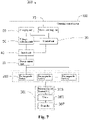
- Charging control circuit 100 Power output end 10 Charging unit 20 Control unit 30 Switch unit 40 Voltage collection unit 50 Mode switching unit 70 Rechargeable battery 200 Movable device 300 Power device 301 Electronic Speed Control (ESC) 303 Motor 305 Propeller 307
- one element when one element is referred to as “electrically connect” another element, it may be directly on another assembly or it is also possible that there is an element between them.
- it When one element is considered to “electrically connect” another element, it may be a contact connection, for example, it may be a wire connection manner, and it may also be a non-contact connection, for example, it may be a non-contact coupling manner.
- an embodiment of the present disclosure provides a charging control circuit 100, used to charge a plurality of rechargeable batteries 200.
- the charging control circuit 100 includes a plurality of power output ends 10, a charging unit 20, a control unit 30, a plurality of switch units 40 corresponding to the power output ends 10 in a one to one manner and a voltage collection unit 50.
- the plurality of power output ends 10 are connected in parallel with each other and each power output end 10 is electrically connected with the charging unit 20, and one of the switch units 40 is further connected between each power output end 10 and the charging unit 20.
- the charging unit 20 may include a power input end, an AC/DC conversion circuit and/or a DC conversion circuit and other circuit modules, used to be electrically connected to an external power supply, and process the external power supply into a corresponding charging voltage which is then output to the power output end 10.
- the control unit 30 may be a Field-Programmable Gate Array (FPGA), a Micro-Controller Unit (MCU) with a control program embedded therein or a single chip computer or the like.
- the control unit 30 may be electrically connected with the plurality of switch units 40 through a control bus, used to output corresponding switch signals to the switch units 40.
- the switch units 40 receive the switch signals sent by the control unit 30, and switch on or switch off electrical connections between the charging unit 20 and the corresponding power output ends 10 in accordance with the switch signals, to cause the charging unit 20 to charge the rechargeable batteries 200 electrically connected to the power output ends 10 through the switch units 40 switched on and the corresponding power output ends 10.
- the switch unit 40 may be a Metal Oxide Semiconductor Field Effect Transistors (MOS transistors), or a relay or other electronic switches.
- MOS transistors Metal Oxide Semiconductor Field Effect Transistors
- the operation manner of the switch unit 40 is described by taking that the switch unit 40 is a MOS transistor as an example, a source of the MOS transistor is connected with the charging unit 20, a drain of the MOS transistor is connected with the corresponding power output end 10, and a gate of the MOS transistor is connected with the control unit 30 through the control bus.
- the control unit 30 sends a corresponding switch signal to the gate of the MOS transistor, for example, a high level signal or a low level signal, so as to control switch-on or switch-off of the MOS transistor.
- the charging unit 20 may charge the rechargeable batteries 200 through the MOS transistor switched on and the corresponding power output end 10.
- the switch unit 40 may also be a NPN type triode or other electronic switches.
- a base of the NPN type triode is connected with the charging unit 30 through the control bus, a collector is electrically connected with the charging unit 20, and an emitter is electrically connected with the corresponding power output end 10.
- the voltage collection unit 50 is electrically connected between the charging unit 20 and the switch unit 40 and electrically connected to the control unit 30.
- the voltage collection unit 50 is used to collect a voltage of each rechargeable battery 200, and transmit the collected voltage of each rechargeable battery 200 to the control unit 30.
- the voltage collected by the voltage collection unit 50 is an output voltage of the charging unit 20.
- the voltage collected by the voltage collection unit 50 is a battery voltage of the rechargeable battery 200 connected to the power output end 10 which corresponds to the switch unit 40 in an on state.
- the control unit 30 controls the switch units 40 to be switched on one by one, to control the voltage collection unit 50 to detect battery voltages of the rechargeable batteries 200 connected to the plurality of power output ends 10 respectively.
- the control unit 30 further controls switch-on and switch-off of the switch units 40 in accordance with the voltages collected by the voltage collection unit 50, so as to switch on or switch off the electrical connections between the charging unit 20 and the corresponding power output ends 10.
- the charging control circuit 100 may further include a mode switching unit 70.
- the mode switching unit 70 is electrically connected with the control unit 30.
- the mode switching unit 70 is used to output a switching signal, for example, a high level signal or a low level signal, to control the charging control circuit 100 to switch between a first charging mode and a second charging mode. For example, when the control unit 30 receives the high level signal sent by the mode switching unit 70, the control unit 30 operates in the first charging mode. When the control unit 30 receives the low level signal sent by the mode switching unit 70, the control unit 30 switches to the second charging mode.
- a switching signal for example, a high level signal or a low level signal
- the switching signal output by the mode switching unit 70 may be implemented by means of hardware or software.
- the mode switching unit 70 includes a button. In this way, when the button is pressed down, the mode switching unit 70 outputs a high level signal to the control unit 30, to control the control unit 30 to switch to the first charging mode. When the button is not pressed down, the mode switching unit 70 outputs a low level signal, to control the control unit 30 to switch to the second charging mode.
- the mode switching unit 70 may also include an automatic switching circuit, the automatic switching circuit being used to automatically output a corresponding high level signal and a low level signal after detecting a preset trigger condition, to switch an operation mode of the charging control circuit 100.
- the charging control circuit 100 may also be set as that, when the mode switching unit 70 does not output any switching signal to the control unit 30, the charging control circuit 100 maintains the existing charging mode, for example, the first charging mode or the second charging mode, however, once the control unit 30 receives a switching signal output by the mode switching unit 70, switching between charging modes is performed, for example, switching from the first charging mode to the second charging mode or switching from the second charging mode to the first charging mode.
- control unit 30 controls the switch units 40 to be switched on one by one, that is, controls the plurality of power output ends 10 to be switched on with the charging unit 20 one by one, so that the voltage collection unit 50 can detect battery voltages of the rechargeable batteries 200 connected onto the plurality of power output ends 10 one by one.
- the control unit 30 further controls the switch unit 40, which corresponds to the rechargeable battery 200 with the maximum voltage value in the battery voltages detected, to be switched on and the other switch units 40 to be powered off, to control the power output end 10, which corresponds to the rechargeable battery 200 with the maximum voltage value in the battery voltages detected, to be switched on and the other power output ends 10 to be powered off, so as to cause the charging unit 20 to first charge the rechargeable battery 200 with the maximum battery voltage value.
- the voltage collection unit 50 detects battery voltages of the remaining rechargeable batteries 200 one by one.
- the control unit 30 further controls the switch unit 40, which corresponds to the rechargeable battery 200 with the maximum voltage value in the remaining rechargeable batteries 200, to be switched on and the other switch units 40 to be switched off, so as to cause the charging unit 20 to charge the rechargeable battery 200 with the maximum voltage value in the remaining rechargeable batteries 200 and charge the rechargeable battery 200 to the first preset value.
- the rest may be deduced by analogy; the control unit 30 controls the charging unit 20 to, in accordance with an order of the battery voltages of the rechargeable batteries 200 from high to low, sequentially charge the plurality of rechargeable batteries 200 all to the first preset value.
- the control unit 30 controls the plurality of switch units 40 to be all switched on, to cause the charging unit 20 to charge all the rechargeable batteries 200 once again and charge the rechargeable batteries 200 to a second preset value.
- the charging control circuit 100 first charges all the rechargeable batteries 200 to the first preset value respectively in accordance with an order of the battery voltages from high to low, and then charges all the rechargeable batteries 200 at the same time, that is, performs parallel charging.
- the plurality of rechargeable batteries 200 are charged at the same time, battery voltage values of the rechargeable batteries 200 are kept consistent, that is, all are the first preset value, therefore, high current discharge from high voltage batteries to low voltage batteries may be avoided, which can achieve an aim of effectively protecting the rechargeable batteries 200, and also shorten charging time of the whole system.
- the charging unit 20 can sequentially charge the plurality of rechargeable batteries 200 to the first preset value by means of constant current charging, and then sequentially charge the plurality of rechargeable batteries 200 from the first preset value to the second preset value by means of constant voltage charging.
- the control unit 30 controls the switch units 40 to be switched on one by one, that is, controls the plurality of power output ends 10 to be switched on with the charging unit 20 one by one, so that the voltage collection unit 50 can detect battery voltages of the rechargeable batteries 200 connected onto the plurality of power output ends 10 one by one.
- the control unit 30 further controls the switch unit 40, which corresponds to the rechargeable battery 200 with the maximum voltage value in the battery voltages detected, to be switched on and the other switch units 40 to be switched off, to control the power output end 10, which corresponds to the rechargeable battery 200 with the maximum voltage value in the battery voltages detected, to be switched on and the other power output ends 10 to be powered off, so as to cause the charging unit 20 to first charge the rechargeable battery 200 with the maximum voltage value and directly charge the rechargeable battery 200 to the second preset value.
- the voltage collection unit 50 detects battery voltages of the remaining rechargeable batteries 200 one by one.
- the control unit 30 further controls the switch unit 40, which corresponds to the rechargeable battery 200 with the maximum voltage value in the remaining rechargeable batteries 200, to be switched on and the other switch units 40 to be switched off, so as to cause the charging unit 20 to charge the rechargeable battery 200 with the maximum battery voltage value in the remaining rechargeable batteries 200 and directly charge the rechargeable battery 200 to the second preset value.
- the rest may be deduced by analogy; the control unit 30 sequentially charges the plurality of rechargeable batteries 200 by detecting battery voltages of the plurality of rechargeable batteries 200 and in accordance with an order of the battery voltages from high to low.
- the charging control circuit 100 may charge the rechargeable battery 200 with the maximum voltage value, and thus one rechargeable battery 200 can be fully charged within the shortest time, to meet use by a user.
- the first preset value is less than the second preset value
- the second preset value may be a rated output voltage value of the rechargeable battery 200 or a voltage value slightly greater than a rated output voltage of the rechargeable battery 200, for example, it may be 1.2 times the rated output voltage value of the rechargeable battery 200.
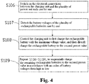
- a charging control method of the charging control circuit 100 provided in an implementation manner of the present disclosure includes the following steps:
- the control unit 30 in the charging control circuit 100 is electrically connected to the mode switching unit 70.
- the mode switching unit 70 is used to output the switching signal, for example, a high level signal or a low level signal, to control the charging control circuit 100 to switch between a first charging mode and a second charging mode.
- the control unit 30 receives the high level signal sent by the mode switching unit 70
- the control unit 30 operates in the first charging mode.
- the control unit 30 receives the low level signal sent by the mode switching unit 70
- the control unit 30 switches to the second charging mode.
- the switching signal output by the mode switching unit 70 may be implemented by means of hardware or software.
- the mode switching unit 70 includes a button.
- the control unit 30 may receive a high level signal sent by the mode switching unit 70, and the control unit 30 switches to the first charging mode.
- the control unit 30 receives a low level signal sent by the mode switching unit 70, and the control unit 30 switches to the second charging mode.
- the mode switching unit 70 may also include an automatic switching circuit, the automatic switching circuit being used to automatically output a corresponding high level signal and a low level signal after detecting a preset trigger condition, to switch an operation mode of the charging control circuit 100.
- S103 Electrical connections between the charging unit 20 and the power output ends 10 are switched on or switched off in accordance with the switch signal.
- the charging control circuit 100 further includes switch units 40, the switch units 40 being electrically connected between the charging unit 20 and the corresponding power output ends 10, and by switching on or switching off the switch units 40, electrical connections between the charging unit 20 and the power output ends 10 are switched on or switched off.
- the charging control circuit 100 may further include a voltage collection unit 50, and the control unit 30 controls the switch units 40 to be switched on one by one, that is, controls the plurality of power output ends 10 to be switched on with the charging unit 20 one by one, to control the voltage collection unit 50 to acquire a battery voltage of each rechargeable battery 200 and control switch-on or switch-off of the switch units 40 in accordance with the collected voltage values.
- the S102 when switching is performed to switch to the first charging mode in accordance with the switching signal, the S102 includes:
- the rechargeable batteries 200 are sequentially charged to a first preset value in accordance with an order of battery voltages of the rechargeable batteries 200 from high to low.
- S104 may include:
- the charging unit 20 may sequentially charge the plurality of rechargeable batteries 200 to the first preset value by means of constant current charging, and then sequentially charge the plurality of rechargeable batteries 200 from the first preset value to the second preset value by means of constant voltage charging.
- the method may include:
- the first preset value is less than the second preset value
- the second preset value may be a rated output voltage value of the rechargeable battery 200 or a voltage value slightly greater than a rated output voltage of the rechargeable battery 200, for example, it may be 1.2 times the rated output voltage value of the rechargeable battery 200.
- the switch unit 40 may also be a switch chip integrated with multiple switches, and the power output end 10 may be a parallel port. Therefore, the number of the switch units 40 and the number of the power output ends 10 both can be reduced to one, and it is only necessary to respectively connect respective ports of the power output end 10 to respective switches of the switch unit 40.
- the aforementioned charging control circuit 100 may be mounted in a housing (not shown), and then form a charging device jointly with the housing.
- the charging device may form a charging system jointly with the plurality of rechargeable batteries 200.
- the charging system may be applied to a movable device 300.
- the movable device 300 may be a vehicle, a ship or the like.
- the movable device 300 may further include a power device 301.
- the charging system may be electrically connected with the power device 301, and used to provide electric energy for the power device 301.
- the movable device 300 is an unmanned aerial vehicle.
- the power device 301 includes an Electronic Speed Control (ESC) 303, a motor 305 and a propeller 307.
- the ESC 303 is electrically connected to the motor 305, and used to control a rotational speed of the motor 305.
- the propeller 307 is mounted on the motor 305, and used to, under the driving of the motor 305, drive the unmanned aerial vehicle 300 to fly.
- the charging system is electrically connected to the ESC 303, used to provide electric energy for the power device 301.
Landscapes
- Engineering & Computer Science (AREA)
- Power Engineering (AREA)
- Charge And Discharge Circuits For Batteries Or The Like (AREA)
- Secondary Cells (AREA)
Claims (13)
- Circuit de commande de charge (100), dans lequel le circuit de commande de charge (100) comprend :une unité de charge (20) ;une pluralité d'extrémités de sortie de puissance (10), respectivement configurées de manière à se connecter à une pluralité de batteries rechargeables (200) et à charger la pluralité de batteries rechargeables (200) ;une unité de commutation (40), dans laquelle l'unité de commutation (40) est connectée entre l'unité de charge (20) et la pluralité d'extrémités de sortie de puissance (10) ;une unité de commande (30) connectée électriquement à l'unité de commutation (40) ; etune unité de commutation de mode (70) connectée électriquement à l'unité de commande (30), dans laquelle l'unité de commutation de mode (70) est configurée de manière à fournir en sortie un signal de commutation destiné à commander au circuit de commande de charge (100) de commuter entre un premier mode de charge et un second mode de charge ; etdans lequel l'unité de commutation de mode (70) comprend un bouton, configuré de manière à amener l'unité de commutation de mode (70) à fournir en sortie le signal de commutation en conséquence de l'actionnement du bouton par un utilisateur ;dans lequel l'unité de commande (30) est configurée de manière à commuter sur le premier mode de charge ou le second mode de charge conformément au signal de commutation envoyé par l'unité de commutation de mode (70), et à fournir en sortie un signal de commutation correspondant à l'unité de commutation (40) ; etdans lequel l'unité de commutation (40) est configurée de manière à activer ou à désactiver des connexions électriques entre l'unité de charge (20) et la pluralité d'extrémités de sortie de puissance (10) conformément au signal de commutation ;dans lequel, lorsque l'unité de commande (30) commute sur le premier mode de charge, l'unité de commande (30) est configurée de manière à commander à l'unité de charge (20) de, conformément à un ordre de tensions de batterie, de la pluralité de batteries rechargeables (200), allant de tensions élevées à faibles, charger séquentiellement la pluralité de batteries rechargeables (200) à une première valeur prédéfinie inférieure à une seconde valeur prédéfinie,et ensuite charger en parallèle, en activant toutes les extrémités de la pluralité d'extrémités de sortie de puissance (10), toutes les batteries rechargeables (200) de la pluralité de batteries rechargeables (200) une fois de plus, et à la seconde valeur prédéfinie ; etdans lequel, lorsque l'unité de commande (30) commute sur le second mode de charge, l'unité de commande (30) est configurée de manière à commander, à l'unité de charge (20) de, conformément à un ordre de tensions de batterie, de la pluralité de batteries rechargeables (200), allant de tensions élevées à faibles, charger séquentiellement la pluralité de batteries rechargeables (200) à la seconde valeur prédéfinie ;dans lequel l'étape de charge séquentielle, dans chacun des premier et second modes de charge, inclut l'activation de l'extrémité de sortie de puissance (10) qui correspond à la batterie rechargeable (200) à charger, et la mise hors tension des autres extrémités de sortie de puissance (10).
- Circuit de commande de charge (100) selon la revendication 1, dans lequel l'unité de commutation (40) est un commutateur à relais ; ouun transistor MOS, dans lequel une source du transistor MOS est connectée électriquement à l'unité de charge (20), un drain du transistor MOS est connecté électriquement à une extrémité de sortie de puissance correspondante (10), et une grille du transistor MOS est connectée électriquement à l'unité de commande (30) ; oul'unité de commutation (40) est une triode de type NPN, un collecteur est électriquement connecté à l'unité de charge (20), un émetteur est électriquement connecté à une extrémité de sortie de puissance correspondante, et une base est électriquement connectée à l'unité de commande (30).
- Circuit de commande de charge (100) selon la revendication 1, dans lequel le circuit de commande de charge (100) comprend en outre une unité de collecte de tension (50), l'unité de collecte de tension (50) étant connectée entre l'unité de charge (20) et l'unité de commutation (40) et connectée à l'unité de commande (30) ; dans lequel l'unité de collecte de tension (50) est configurée de manière à collecter des valeurs de tension des batteries rechargeables (200), et l'unité de commande (30), conformément aux valeurs de tension collectées par l'unité de collecte de tension (50), est configurée de manière à commander l'activation ou la désactivation des connexions électriques entre la pluralité d'extrémités de sortie de puissance (10) et l'unité de charge (20), par l'intermédiaire de l'unité de commutation (40).
- Circuit de commande de charge (100) selon la revendication 1, dans lequel l'unité de commande (30) est configurée de manière à commander l'activation de la pluralité d'extrémités de sortie de puissance (10) avec l'unité de charge (20), une par une, par l'intermédiaire de l'unité de commutation (40), afin de commander, à l'unité de collecte de tension (50), de collecter une tension de batterie de chaque batterie rechargeable (200).
- Circuit de commande de charge (100) selon la revendication 1, dans lequel, lorsque l'unité de commande (30) commute sur le premier mode de charge, l'unité de commande (30) est configurée de manière à commander à l'unité de commutation (40) de, conformément à un ordre de tensions de batterie, allant de tensions élevées à faibles, activer séquentiellement l'extrémité de sortie de puissance (10) qui correspond à la batterie rechargeable (200) avec une valeur de tension maximale dans la pluralité de batteries rechargeables (200), et mettre hors tension les autres extrémités de sortie de puissance (10), de manière à commander, à l'unité de charge (20), de charger séquentiellement la pluralité de batteries rechargeables (200) à la première valeur prédéfinie, et ensuite activer toutes les extrémités de la pluralité d'extrémités de sortie de puissance (10), en vue d'amener l'unité de charge (20) à charger toutes les batteries rechargeables (200) une fois de plus et à charger les batteries rechargeables (200) à la seconde valeur prédéfinie.
- Circuit de commande de charge (100) selon la revendication 5, dans lequel l'unité de commande (30) est configurée de manière à commander l'activation de la pluralité d'extrémités de sortie de puissance (10) avec l'unité de charge (20), une par une, par l'intermédiaire de l'unité de commutation (40), de manière à amener l'unité de collecte de tension (50) à détecter des tensions de batterie de la pluralité de batteries rechargeables (200), une par une, et l'unité de commande (30) est en outre configurée de manière à commander l'activation de l'extrémité de sortie de puissance, qui correspond à la batterie rechargeable présentant la valeur de tension maximale dans les tensions de batterie détectées, et la mise hors tension des autres extrémités de sortie de puissance (10), en vue d'amener l'unité de charge (20) à charger la batterie rechargeable, présentant la valeur de tension de batterie maximale, à la première valeur prédéfinie.
- Circuit de commande de charge (100) selon la revendication 1, dans lequel, lorsque l'unité de commande (30) commute sur le second mode de charge, l'unité de commande (30) est configurée de manière à commander, à l'unité de commutation (40), de, conformément à un ordre de tensions de batterie, des batteries rechargeables (200), allant de tensions élevées à faibles, activer séquentiellement l'extrémité de sortie de puissance qui correspond à la batterie rechargeable présentant une valeur de tension maximale dans les batteries rechargeables (200), et mettre hors tension les autres extrémités de sortie de puissance (10), de façon à commander, à l'unité de charge (20), de charger séquentiellement les batteries rechargeables (200) à la seconde valeur prédéfinie.
- Circuit de commande de charge (100) selon la revendication 7, dans lequel l'unité de commande (30) est configurée de manière à commander l'activation de la pluralité d'extrémités de sortie de puissance (10), avec l'unité de charge (20), une par une, par l'intermédiaire de l'unité de commutation (40), de manière à amener l'unité de collecte de tension (50) à détecter des tensions de batterie de la pluralité de batteries rechargeables (200), une par une, et l'unité de commande (30) est en outre configurée de manière à commander l'activation de l'extrémité de sortie de puissance (10), qui correspond à la batterie rechargeable (200) présentant la valeur de tension maximale dans la pluralité de tensions de batterie détectées, et la mise hors tension des autres extrémités de sortie de puissance (10), en vue d'amener l'unité de charge (20) à charger séquentiellement la batterie rechargeable (200), présentant la valeur de tension de batterie maximale, à la seconde valeur prédéfinie.
- Circuit de commande de charge (100) selon l'une quelconque des revendications 5 à 8, dans lequel l'unité de commande (30) est configurée de manière à commander la mise hors tension d'une extrémité de sortie de puissance correspondante (10) lorsqu'une tension de charge d'une batterie rechargeable (200) atteint la seconde valeur prédéfinie.
- Système de charge, dans lequel le système de charge comprend une pluralité de batteries rechargeables (200), et le circuit de commande de charge (100) selon l'une quelconque des revendications 1 à 9 utilisé pour charger la pluralité de batteries rechargeables (200).
- Procédé de commande de charge, dans lequel le procédé comprend les étapes ci-dessous consistant à :fournir en sortie un signal de commutation, par le biais d'une unité de commutation de mode, pour commuter entre un premier mode de charge et un second mode de charge, dans lequel le signal de commutation est fourni en sortie à la suite de l'actionnement, par un utilisateur, d'un bouton de l'unité de commutation de mode comprise dans un circuit de commande de charge ;acquérir le signal de commutation ;commuter sur le premier mode de charge ou sur le second mode de charge conformément au signal de commutation, et fournir en sortie un signal de commutation correspondant, par le biais du circuit de commande de charge ; etactiver ou désactiver des connexions électriques, par le biais d'une unité de commutation entre une unité de charge (20) et une pluralité d'extrémités de sortie de puissance (10), conformément au signal de commutation, dans lequel les extrémités de la pluralité d'extrémités de sortie de puissance (10) sont utilisées pour se connecter à une pluralité de batteries rechargeables (200), respectivement, et l'unité de charge (20) charge la pluralité de batteries rechargeables (200) par l'intermédiaire de la pluralité d'extrémités de sortie de puissance (10) ;dans lequel l'étape de commutation sur le premier mode de charge, conformément au signal de commutation, comprend les étapes ci-dessous consistant à :charger séquentiellement la pluralité de batteries rechargeables (200) à une première valeur prédéfinie inférieure à une seconde valeur prédéfinie, conformément à un ordre de tensions de batterie, des batteries rechargeables (200), allant de tensions élevées à faibles ; etcommander, à l'unité de charge (20), de charger en parallèle, en activant toutes les extrémités de la pluralité d'extrémités de sortie de puissance (10), toutes les batteries rechargeables (200), une fois de plus, et à la seconde valeur prédéfinie ;dans lequel l'étape de commutation, sur le second mode de charge, conformément au signal de commutation, comprend l'étape ci-dessous consistant à :charger séquentiellement la pluralité de batteries rechargeables (200), à la seconde valeur prédéfinie, conformément à un ordre de tensions de batterie, de la pluralité de batteries rechargeables (200), allant de tensions élevées à faibles ; etdans lequel l'étape de charge séquentielle dans chacun des premier et second modes de charge inclut l'activation de l'extrémité de sortie de puissance (10), qui correspond à la batterie rechargeable (200) à charger, et la mise hors tension des autres extrémités de sortie de puissance (10).
- Procédé de commande de charge selon la revendication 11, dans lequel l'étape de charge séquentielle de la pluralité de batteries rechargeables (200) à une première valeur prédéfinie conformément à un ordre de tensions de batterie, des batteries rechargeables (200), allant de tensions élevées à faibles, comprend les étapes ci-dessous consistant à :(a) activer les connexions électriques entre l'unité de charge (20) et la pluralité d'extrémités de sortie de puissance, une par une ;(b) détecter les tensions de batterie de la pluralité de batteries rechargeables (200), une par une ;(c) commander, à l'unité de charge (20), de charger la batterie rechargeable présentant la valeur de tension de batterie maximale, à la première valeur prédéfinie ; et répéter les étapes (a) à (c), en vue de charger séquentiellement les batteries rechargeables restantes (200) à la première valeur prédéfinie, conformément à un ordre de tensions de batterie, allant de tensions élevées à faibles.
- Procédé de commande de charge selon la revendication 11, dans lequel l'étape de commutation sur un second mode de charge, conformément au signal de commutation, comprend les étapes ci-dessous consistant à :(d) activer les connexions électriques entre l'unité de charge (20) et la pluralité d'extrémités de sortie de puissance, une par une ;(e) détecter les tensions de batterie de la pluralité de batteries rechargeables (200), une par une ;(f) commander, à l'unité de charge (20), de charger tout d'abord la batterie rechargeable présentant la valeur de tension maximale, et ensuite charger directement la batterie rechargeable à une seconde valeur prédéfinie ; et
répéter les étapes (d) à (f), en vue de charger séquentiellement les batteries rechargeables restantes (200) à la seconde valeur prédéfinie, conformément à un ordre de tensions de batterie, allant de tensions élevées à faibles.
Applications Claiming Priority (1)
| Application Number | Priority Date | Filing Date | Title |
|---|---|---|---|
| PCT/CN2015/082827 WO2017000216A1 (fr) | 2015-06-30 | 2015-06-30 | Circuit de commande de charge, dispositif de charge, système de charge et procédé de commande de charge |
Publications (3)
| Publication Number | Publication Date |
|---|---|
| EP3319196A1 EP3319196A1 (fr) | 2018-05-09 |
| EP3319196A4 EP3319196A4 (fr) | 2018-05-16 |
| EP3319196B1 true EP3319196B1 (fr) | 2022-04-27 |
Family
ID=57607465
Family Applications (1)
| Application Number | Title | Priority Date | Filing Date |
|---|---|---|---|
| EP15896747.1A Not-in-force EP3319196B1 (fr) | 2015-06-30 | 2015-06-30 | Circuit de commande de charge, dispositif de charge, système de charge et procédé de commande de charge |
Country Status (5)
| Country | Link |
|---|---|
| US (1) | US10587128B2 (fr) |
| EP (1) | EP3319196B1 (fr) |
| JP (1) | JP2017525323A (fr) |
| CN (1) | CN107112767B (fr) |
| WO (1) | WO2017000216A1 (fr) |
Families Citing this family (12)
| Publication number | Priority date | Publication date | Assignee | Title |
|---|---|---|---|---|
| WO2018222261A1 (fr) * | 2017-06-01 | 2018-12-06 | Florida Atlantic University Board Of Trustees | Systèmes et procédés de gestion d'alimentation fédérée |
| EP3811441B1 (fr) * | 2018-06-22 | 2023-06-07 | Bourns, Inc. | Disjoncteurs |
| CN109159674B (zh) * | 2018-09-03 | 2020-08-21 | 广东嘉腾机器人自动化有限公司 | 一种充电电路及系统 |
| US11025072B2 (en) | 2018-10-17 | 2021-06-01 | Ess Tech, Inc. | System and method for operating an electrical energy storage system |
| CN111884272A (zh) * | 2019-05-03 | 2020-11-03 | 深圳市倍斯特科技股份有限公司 | 一种充电方法 |
| CN110676898B (zh) * | 2019-09-16 | 2023-06-02 | Oppo广东移动通信有限公司 | 待充电设备 |
| AU2021247172A1 (en) | 2020-04-01 | 2022-09-15 | University Of Florida Research Foundation, Incorporated | Dual AAV-MY07A vectors with improved safety for the treatment of USH1B |
| CN111682615A (zh) * | 2020-06-18 | 2020-09-18 | 格力博(江苏)股份有限公司 | 充电控制电路、充电装置及充电系统 |
| EP4015287B1 (fr) * | 2020-12-21 | 2025-01-22 | Volvo Truck Corporation | Système de chargement pour un stockage d'énergie dans un véhicule et procédé de commande du système de chargement |
| EP4015296A1 (fr) | 2020-12-21 | 2022-06-22 | Volvo Truck Corporation | Système de chargement pour véhicule et procédé de commande du système de chargement |
| JP7773342B2 (ja) | 2021-11-05 | 2025-11-19 | Fdk株式会社 | バッテリバンクユニット、充電残時間算出方法、および、充電残時間算出プログラム |
| JP7773343B2 (ja) * | 2021-11-05 | 2025-11-19 | Fdk株式会社 | バッテリバンクユニット、充電残時間算出方法、および、充電残時間算出プログラム |
Family Cites Families (108)
| Publication number | Priority date | Publication date | Assignee | Title |
|---|---|---|---|---|
| US4849682A (en) * | 1987-10-30 | 1989-07-18 | Anton/Bauer, Inc. | Battery charging system |
| JPH0287937A (ja) * | 1988-09-21 | 1990-03-28 | Sanyo Electric Co Ltd | 充電装置 |
| US5057762A (en) * | 1990-07-30 | 1991-10-15 | Motorola, Inc. | System for determining battery charge states and charging sequence for a battery charger |
| US5218286A (en) * | 1991-09-16 | 1993-06-08 | Monarch Marking Systems, Inc. | Multichannel battery charger |
| JPH06303729A (ja) * | 1993-04-13 | 1994-10-28 | Sony Corp | 充電装置 |
| JPH0997629A (ja) * | 1995-09-29 | 1997-04-08 | Sanyo Electric Co Ltd | 複数のリチウムイオン二次電池の充電方法 |
| JP3934700B2 (ja) * | 1996-02-07 | 2007-06-20 | ソニー株式会社 | バッテリ充電装置およびバッテリ充電方法 |
| US5780991A (en) * | 1996-07-26 | 1998-07-14 | Telxon Corporation | Multiple station charging apparatus with single charging power supply for parallel charging |
| JP3208655B2 (ja) * | 1996-08-13 | 2001-09-17 | 富士通電装株式会社 | 電気自動車用充電装置 |
| US5914606A (en) * | 1996-10-10 | 1999-06-22 | Becker-Irvin; Craig H. | Battery cell voltage monitor and method |
| JP3571536B2 (ja) * | 1997-10-20 | 2004-09-29 | 富士通株式会社 | バッテリ充電装置及び方法並びに電子装置 |
| US6137261A (en) * | 1998-01-26 | 2000-10-24 | Physio-Control Manufacturing Corporation | Rechargeable battery maintenance and testing system |
| KR100793194B1 (ko) * | 2001-07-05 | 2008-01-10 | 엘지전자 주식회사 | 다중 배터리 충전방법 및 충전장치 |
| JP3886389B2 (ja) * | 2002-02-07 | 2007-02-28 | 株式会社リコー | 電池パック充電装置および充電方法 |
| JP2003288951A (ja) * | 2002-03-27 | 2003-10-10 | Fuji Heavy Ind Ltd | 鉛蓄電池の充電方法 |
| TW571452B (en) | 2002-12-13 | 2004-01-11 | Quanta Comp Inc | Charging-type electrical potential balance device |
| JP2004357481A (ja) * | 2003-05-30 | 2004-12-16 | Sanyo Electric Co Ltd | 複数のバッテリを充電する方法と放電する方法 |
| US7081737B2 (en) * | 2003-06-19 | 2006-07-25 | O2Micro International Limited | Battery cell monitoring and balancing circuit |
| US7859224B2 (en) * | 2005-05-26 | 2010-12-28 | Shop-Vac Corporation | Charge control circuit for a vehicle vacuum cleaner battery |
| US7456611B2 (en) * | 2005-08-11 | 2008-11-25 | Semiconductor Components Industries, L.L.C. | Multi-current battery charger circuit and method therefor |
| EP2006973A4 (fr) * | 2006-03-03 | 2012-03-07 | Nec Corp | Systeme d'alimentation electrique |
| US7839121B2 (en) * | 2006-03-20 | 2010-11-23 | Lg Electronics Inc. | Apparatus and method for managing power of battery packs in a portable device |
| US7679335B1 (en) * | 2006-07-07 | 2010-03-16 | Collins Ralph C | Battery charger for aircraft emergency egress batteries |
| CN201017967Y (zh) * | 2007-03-05 | 2008-02-06 | 南京德朔实业有限公司 | 一种带有自充功能的锂电系统 |
| JP5118913B2 (ja) * | 2007-07-24 | 2013-01-16 | トヨタ自動車株式会社 | 電源システムおよびそれを備えた電動車両ならびに電源システムの制御方法 |
| JP5146726B2 (ja) * | 2007-10-25 | 2013-02-20 | 日立工機株式会社 | 充電装置 |
| US8169191B2 (en) * | 2008-02-25 | 2012-05-01 | Werthman Dean A | System for use in gathering or processing data in a healthcare facility having fleet of mobile workstations |
| US7782607B2 (en) * | 2008-02-25 | 2010-08-24 | Stinger Industries LLC | Mobile workstation having power system with removable battery configured for drop-in engagement therewith |
| US8775828B2 (en) * | 2008-02-25 | 2014-07-08 | Gary Coonan | Power control system for mobile workstation and method |
| US7855530B2 (en) * | 2008-02-25 | 2010-12-21 | Stinger Industries, Llc | Battery charging system and method of reducing variation in battery charging cycle count |
| US7800255B2 (en) * | 2008-02-25 | 2010-09-21 | Stinger Industries LLC | Power system for mobile workstation and method |
| US7830668B2 (en) * | 2008-02-25 | 2010-11-09 | Stinger Industries LLC | Power supply unit for mobile workstation and method |
| US8227943B2 (en) * | 2008-02-25 | 2012-07-24 | Lee Melvin Harbin | Power system retrofit kit for mobile workstation and retrofit method |
| US8160727B2 (en) * | 2008-02-25 | 2012-04-17 | Gary Coonan | Mobile workstation control system configured for power system and peripheral device control |
| US8519671B2 (en) * | 2008-09-15 | 2013-08-27 | Blackberry Limited | Power supply circuit and method for providing output voltage to charge a battery |
| WO2010052738A1 (fr) * | 2008-11-10 | 2010-05-14 | Himangshu Rai Vaish | Systèmes et procédés de charge solaire d'accumulateurs |
| CN101740732B (zh) * | 2008-11-12 | 2012-09-19 | 深圳富泰宏精密工业有限公司 | 电池固定装置 |
| US7612997B1 (en) * | 2008-11-17 | 2009-11-03 | Incase Designs Corp. | Portable electronic device case with battery |
| JP5326517B2 (ja) * | 2008-11-21 | 2013-10-30 | ソニー株式会社 | 集積回路およびそれを用いた電池パック |
| US9762069B2 (en) * | 2009-05-19 | 2017-09-12 | Duracell U.S. Operations, Inc. | Multi-use fast rate charging stand |
| US9197081B2 (en) * | 2009-08-28 | 2015-11-24 | The Charles Stark Draper Laboratory, Inc. | High-efficiency battery equalization for charging and discharging |
| KR100946635B1 (ko) * | 2009-09-16 | 2010-03-09 | 제이엠씨엔지니어링 주식회사 | 다채널 4단자망 충전 장치·다채널 배터리 전원 공급모듈로 이루어진 배터리 팩 장치 |
| US20110193518A1 (en) * | 2010-02-10 | 2011-08-11 | James Wright | Battery override |
| US8415923B2 (en) * | 2010-04-23 | 2013-04-09 | Psion Inc. | External battery charging unit |
| DE102010040721A1 (de) * | 2010-09-14 | 2012-03-15 | Sb Limotive Company Ltd. | Batteriesystem mit Zellspannungserfassungseinheiten |
| GB2484773B (en) * | 2010-10-21 | 2013-09-11 | Chervon Hk Ltd | Battery charging system having multiple charging modes |
| US8089249B2 (en) * | 2010-11-08 | 2012-01-03 | O2Micro, Inc. | Battery management systems and methods |
| US20120126747A1 (en) * | 2010-11-19 | 2012-05-24 | Delphi Technologies, Inc. | Battery charger having non-contact electrical switch |
| CN102480142B (zh) * | 2010-11-26 | 2015-07-22 | 比亚迪股份有限公司 | 电池组并联充电装置及其并联充电方法 |
| US8773068B2 (en) * | 2011-01-20 | 2014-07-08 | Valence Technology, Inc. | Rechargeable battery systems and rechargeable battery system operational methods |
| TWI474160B (zh) * | 2011-03-07 | 2015-02-21 | Quanta Comp Inc | 電腦系統與其操作方法 |
| WO2012127764A1 (fr) * | 2011-03-23 | 2012-09-27 | 三洋電機株式会社 | Système de batterie, dispositif d'égalisation, système d'égalisation, véhicule électrique, corps mobile, dispositif de stockage d'énergie et dispositif d'alimentation électrique |
| KR101256077B1 (ko) * | 2011-04-18 | 2013-04-18 | 삼성에스디아이 주식회사 | 전력 제어 시스템 및 전력 제어 방법 |
| WO2012172685A1 (fr) * | 2011-06-17 | 2012-12-20 | トヨタ自動車株式会社 | Système d'alimentation électrique, véhicule doté de celui-ci et procédé de commande de système d'alimentation électrique |
| WO2012177193A1 (fr) * | 2011-06-21 | 2012-12-27 | Husqvarna Ab | Système et procédé pour charger une pile rechargeable |
| EP2541728A2 (fr) * | 2011-06-30 | 2013-01-02 | Kabushiki Kaisha Toyota Jidoshokki | Dispositif d'équilibrage de cellule |
| WO2013073173A1 (fr) | 2011-11-14 | 2013-05-23 | パナソニック株式会社 | Appareil de chargement de batterie |
| US20130134933A1 (en) * | 2011-11-29 | 2013-05-30 | Delphi Technologies, Inc. | Power safety system and method having a plurality of thermally-triggered electrical breaking arrangements |
| CN102570545B (zh) * | 2011-12-24 | 2014-01-15 | 鸿富锦精密工业(深圳)有限公司 | 充电控制电路 |
| CN102623768B (zh) * | 2012-03-30 | 2014-08-27 | 青岛海信移动通信技术股份有限公司 | 一种多电池充电方法、装置以及一种手持移动终端 |
| KR102158288B1 (ko) * | 2012-07-09 | 2020-09-21 | 삼성전자주식회사 | 배터리를 충전하기 위한 방법 및 그 전자 장치 |
| US9142999B2 (en) * | 2012-07-13 | 2015-09-22 | Qualcomm Incorporated | Systems, methods, and apparatus for small device wireless charging modes |
| EP2882068B8 (fr) * | 2012-08-02 | 2016-05-18 | Nissan Motor Co., Ltd. | Système de gestion de charge destiné à des véhicules de transport sans pilote |
| KR101975395B1 (ko) * | 2012-08-29 | 2019-05-07 | 삼성에스디아이 주식회사 | 배터리 팩 및 이의 제어 방법 |
| US20140167683A1 (en) * | 2012-12-13 | 2014-06-19 | John Manford Wade | Multiple cell battery management |
| US9337683B2 (en) * | 2012-12-20 | 2016-05-10 | Powergenix Systems, Inc. | Controlling battery states of charge in systems having separate power sources |
| US10374447B2 (en) * | 2013-03-14 | 2019-08-06 | Infineon Technologies Austria Ag | Power converter circuit including at least one battery |
| US20140265945A1 (en) * | 2013-03-15 | 2014-09-18 | Infineon Technologies Austria Ag | Electric Drive System |
| WO2014156041A1 (fr) * | 2013-03-29 | 2014-10-02 | 三洋電機株式会社 | Système d'alimentation électrique et procédé de commande de charge et décharge pour système d'alimentation électrique |
| CN103280854B (zh) * | 2013-05-23 | 2018-10-02 | 浙江吉利汽车研究院有限公司杭州分公司 | 汽车动力电池充电系统及充电方法 |
| US20150162781A1 (en) * | 2013-12-06 | 2015-06-11 | Lsi Corporation | Illumination-Based Charging System for Portable Devices |
| US9592744B2 (en) * | 2013-12-06 | 2017-03-14 | SZ DJI Technology Co., Ltd | Battery and unmanned aerial vehicle with the battery |
| US9726731B2 (en) * | 2013-12-31 | 2017-08-08 | Chervon (Hk) Limited | Battery pack, method for detecting battery pack, charging assembly and electric tool |
| US9806612B2 (en) * | 2014-01-17 | 2017-10-31 | Grenotek Integrated, Inc. | Systems and methods of energy saving in a battery charging system |
| US9634517B2 (en) * | 2014-02-17 | 2017-04-25 | Lenovo (Singapore) Pte. Ltd. | Battery charging mode selection |
| JP6187309B2 (ja) * | 2014-02-21 | 2017-08-30 | トヨタ自動車株式会社 | 電動車両の電源装置 |
| US10826313B2 (en) * | 2014-02-28 | 2020-11-03 | Apple Inc. | Power management systems for product demonstration fixtures |
| US9923392B2 (en) * | 2014-04-03 | 2018-03-20 | Halo2Cloud, LLC | Power charger with charge indicating power button |
| US9601938B2 (en) * | 2014-05-15 | 2017-03-21 | Intel Corporation | Battery charger for different power sources |
| CN108565920B (zh) * | 2014-06-12 | 2021-07-27 | 深圳市大疆创新科技有限公司 | 一种充电系统、供电装置及飞行器 |
| EP3197007B1 (fr) * | 2014-09-18 | 2019-03-06 | Takashin Co., Ltd. | Système de charge |
| US10283976B2 (en) * | 2014-10-27 | 2019-05-07 | Beijing Yuanlong Yato Culture Dissemination Co., Ltd. | Multifunctional data mobile power supply and charging method |
| WO2016074134A1 (fr) * | 2014-11-10 | 2016-05-19 | 深圳市大疆创新科技有限公司 | Batterie, son appareil de régulation de chaleur et uav comportant la batterie |
| CN204361767U (zh) * | 2014-12-04 | 2015-05-27 | 深圳市大疆创新科技有限公司 | 充电器及其充电控制电路 |
| EP3419134B1 (fr) * | 2014-12-17 | 2020-08-05 | SZ DJI Technology Co., Ltd. | Système de gestion de batterie |
| CN105706292B (zh) * | 2014-12-30 | 2018-02-02 | 深圳市大疆创新科技有限公司 | 一种电池预热方法、装置及设备 |
| WO2016172946A1 (fr) * | 2015-04-30 | 2016-11-03 | 深圳市大疆创新科技有限公司 | Chargeur, système de charge comprenant le chargeur et aéronef |
| KR102377394B1 (ko) * | 2015-05-14 | 2022-03-22 | 삼성에스디아이 주식회사 | 에너지 저장 시스템 및 그 구동 방법 |
| WO2017000103A1 (fr) * | 2015-06-29 | 2017-01-05 | 深圳市大疆创新科技有限公司 | Circuit de commande, batterie pourvue du circuit de commande, et procédé de commande de batterie |
| WO2017000238A1 (fr) * | 2015-06-30 | 2017-01-05 | 深圳市大疆创新科技有限公司 | Procédé de gestion de batterie, batterie unique, système de commande de vol et véhicule aérien sans pilote |
| US10326294B2 (en) * | 2015-07-17 | 2019-06-18 | Dell Products, Lp | System and method for green battery conditioning |
| US9690349B2 (en) * | 2015-07-30 | 2017-06-27 | Dell Products L.P. | Systems and methods for enhancing system hold up time using reverse charging of power supply unit |
| US9735590B2 (en) * | 2015-08-28 | 2017-08-15 | Dell Products L.P. | Systems and methods for hidden battery cell charging and conditioning |
| CN107250822B (zh) * | 2015-12-03 | 2020-09-01 | 深圳市大疆创新科技有限公司 | 用于确定电池的运行状态的系统和方法 |
| CN108432081A (zh) * | 2015-12-31 | 2018-08-21 | 深圳市大疆创新科技有限公司 | 用于管理电池组件的方法和系统 |
| CN107251363B (zh) * | 2015-12-31 | 2020-09-29 | 深圳市大疆创新科技有限公司 | 用于使电池组件平衡的方法和系统 |
| WO2017113337A1 (fr) * | 2015-12-31 | 2017-07-06 | SZ DJI Technology Co., Ltd. | Batterie intelligente et procédé |
| WO2017133389A1 (fr) * | 2016-02-05 | 2017-08-10 | 广东欧珀移动通信有限公司 | Système de charge de terminal, procédé de charge et adaptateur d'alimentation |
| SG11201700428UA (en) * | 2016-02-05 | 2017-09-28 | Guangdong Oppo Mobile Telecommunications Corp Ltd | Charge method, adapter and mobile terminal |
| CN108780972B (zh) * | 2016-02-29 | 2020-12-04 | 深圳市大疆创新科技有限公司 | 电连接器 |
| WO2017206064A1 (fr) * | 2016-05-31 | 2017-12-07 | 深圳市大疆创新科技有限公司 | Procédé et système de commande de batterie, batterie intelligente et plate-forme mobile |
| CN107438917B (zh) * | 2016-07-01 | 2019-09-10 | 深圳市大疆创新科技有限公司 | 金属电池及其电池管理系统、控制方法 |
| CN109565180B (zh) * | 2016-07-12 | 2023-03-17 | 深圳市大疆创新科技有限公司 | 用于电池管理的系统和方法 |
| WO2018014336A1 (fr) * | 2016-07-22 | 2018-01-25 | SZ DJI Technology Co., Ltd. | Procédé et système d'alimentation en énergie d'un véhicule aérien sans équipage |
| EP3723231B1 (fr) * | 2016-07-26 | 2021-10-06 | Guangdong Oppo Mobile Telecommunications Corp., Ltd. | Système de recharge, procédé de recharge et adaptateur de puissance |
| CN205971879U (zh) * | 2016-08-23 | 2017-02-22 | 深圳市大疆创新科技有限公司 | 无人飞行器 |
| WO2018086142A1 (fr) * | 2016-11-14 | 2018-05-17 | SZ DJI Technology Co., Ltd. | Système multi-batterie et gestion associée |
| CN207304056U (zh) * | 2017-08-18 | 2018-05-01 | 深圳市正浩创新科技有限公司 | 移动电源 |
-
2015
- 2015-06-30 EP EP15896747.1A patent/EP3319196B1/fr not_active Not-in-force
- 2015-06-30 WO PCT/CN2015/082827 patent/WO2017000216A1/fr not_active Ceased
- 2015-06-30 JP JP2016546089A patent/JP2017525323A/ja active Pending
- 2015-06-30 CN CN201580001161.5A patent/CN107112767B/zh active Active
-
2017
- 2017-12-29 US US15/858,951 patent/US10587128B2/en active Active
Also Published As
| Publication number | Publication date |
|---|---|
| WO2017000216A1 (fr) | 2017-01-05 |
| US10587128B2 (en) | 2020-03-10 |
| US20180123362A1 (en) | 2018-05-03 |
| EP3319196A4 (fr) | 2018-05-16 |
| CN107112767A (zh) | 2017-08-29 |
| CN107112767B (zh) | 2019-06-07 |
| JP2017525323A (ja) | 2017-08-31 |
| EP3319196A1 (fr) | 2018-05-09 |
Similar Documents
| Publication | Publication Date | Title |
|---|---|---|
| EP3319196B1 (fr) | Circuit de commande de charge, dispositif de charge, système de charge et procédé de commande de charge | |
| EP2092627B1 (fr) | Système de gestion de batteries | |
| CN101765958B (zh) | 用于平衡电池组单元电池的电荷容量的设备和方法 | |
| EP2733814B1 (fr) | Dispositif, procédé et équipement utilisateur pour alimentation électrique | |
| JP7039773B2 (ja) | バッテリーパックを含む電力システム | |
| US11637433B2 (en) | Battery pack and electrical apparatus | |
| US10630101B2 (en) | Charging-discharging module of energy storage unit and charging-discharging method thereof | |
| CN112311038A (zh) | 一种充放电保护电路、终端设备及电池放电控制方法 | |
| KR20140044127A (ko) | 멀티 bms 기동 장치 | |
| CN204905906U (zh) | 充电控制电路、充电装置及充电系统 | |
| US20210384724A1 (en) | Restart protection device | |
| US10897134B2 (en) | Electronic device | |
| EP3467993A1 (fr) | Unité d'alimentation électrique au sol actionné par batterie avec construction, durabilité et maintenance améliorées | |
| CN109245245A (zh) | 一种电池的防反向充电电路及电池管理系统 | |
| CN102457087A (zh) | 电功率路径切换方法和电功率路径切换电路 | |
| KR20130009411A (ko) | 보조배터리를 이용한 마스터장치의 충전장치 및 방법 | |
| US20200287400A1 (en) | Battery control circuit and electronic device | |
| CN110892603A (zh) | 电池控制电路、电池和无人机 | |
| CN108495788A (zh) | 充电系统及充电方法 | |
| CN211790810U (zh) | 充电系统、充电器、电池组及可移动平台 | |
| CN110063028B (zh) | 电池组的通信系统以及包括其的电池组 | |
| CN110809845B (zh) | 蓄电池组件 | |
| CN105162078B (zh) | 一种终端的充电保护电路及方法和终端 | |
| CN103928963A (zh) | 可充电电池、充电方法、以及无人机 | |
| EP3993116A1 (fr) | Bloc-batterie rechargeable et aspirateur portatif |
Legal Events
| Date | Code | Title | Description |
|---|---|---|---|
| STAA | Information on the status of an ep patent application or granted ep patent |
Free format text: STATUS: THE INTERNATIONAL PUBLICATION HAS BEEN MADE |
|
| PUAI | Public reference made under article 153(3) epc to a published international application that has entered the european phase |
Free format text: ORIGINAL CODE: 0009012 |
|
| STAA | Information on the status of an ep patent application or granted ep patent |
Free format text: STATUS: REQUEST FOR EXAMINATION WAS MADE |
|
| 17P | Request for examination filed |
Effective date: 20171227 |
|
| AK | Designated contracting states |
Kind code of ref document: A1 Designated state(s): AL AT BE BG CH CY CZ DE DK EE ES FI FR GB GR HR HU IE IS IT LI LT LU LV MC MK MT NL NO PL PT RO RS SE SI SK SM TR |
|
| AX | Request for extension of the european patent |
Extension state: BA ME |
|
| A4 | Supplementary search report drawn up and despatched |
Effective date: 20180412 |
|
| RIC1 | Information provided on ipc code assigned before grant |
Ipc: H02J 7/00 20060101AFI20180406BHEP |
|
| DAV | Request for validation of the european patent (deleted) | ||
| DAX | Request for extension of the european patent (deleted) | ||
| STAA | Information on the status of an ep patent application or granted ep patent |
Free format text: STATUS: EXAMINATION IS IN PROGRESS |
|
| 17Q | First examination report despatched |
Effective date: 20200304 |
|
| GRAP | Despatch of communication of intention to grant a patent |
Free format text: ORIGINAL CODE: EPIDOSNIGR1 |
|
| STAA | Information on the status of an ep patent application or granted ep patent |
Free format text: STATUS: GRANT OF PATENT IS INTENDED |
|
| INTG | Intention to grant announced |
Effective date: 20211208 |
|
| GRAS | Grant fee paid |
Free format text: ORIGINAL CODE: EPIDOSNIGR3 |
|
| GRAA | (expected) grant |
Free format text: ORIGINAL CODE: 0009210 |
|
| STAA | Information on the status of an ep patent application or granted ep patent |
Free format text: STATUS: THE PATENT HAS BEEN GRANTED |
|
| AK | Designated contracting states |
Kind code of ref document: B1 Designated state(s): AL AT BE BG CH CY CZ DE DK EE ES FI FR GB GR HR HU IE IS IT LI LT LU LV MC MK MT NL NO PL PT RO RS SE SI SK SM TR |
|
| REG | Reference to a national code |
Ref country code: GB Ref legal event code: FG4D |
|
| REG | Reference to a national code |
Ref country code: CH Ref legal event code: EP |
|
| REG | Reference to a national code |
Ref country code: AT Ref legal event code: REF Ref document number: 1487713 Country of ref document: AT Kind code of ref document: T Effective date: 20220515 |
|
| REG | Reference to a national code |
Ref country code: DE Ref legal event code: R096 Ref document number: 602015078590 Country of ref document: DE |
|
| REG | Reference to a national code |
Ref country code: IE Ref legal event code: FG4D |
|
| PGFP | Annual fee paid to national office [announced via postgrant information from national office to epo] |
Ref country code: DE Payment date: 20220620 Year of fee payment: 8 |
|
| REG | Reference to a national code |
Ref country code: LT Ref legal event code: MG9D |
|
| REG | Reference to a national code |
Ref country code: NL Ref legal event code: MP Effective date: 20220427 |
|
| REG | Reference to a national code |
Ref country code: AT Ref legal event code: MK05 Ref document number: 1487713 Country of ref document: AT Kind code of ref document: T Effective date: 20220427 |
|
| PG25 | Lapsed in a contracting state [announced via postgrant information from national office to epo] |
Ref country code: NL Free format text: LAPSE BECAUSE OF FAILURE TO SUBMIT A TRANSLATION OF THE DESCRIPTION OR TO PAY THE FEE WITHIN THE PRESCRIBED TIME-LIMIT Effective date: 20220427 |
|
| PG25 | Lapsed in a contracting state [announced via postgrant information from national office to epo] |
Ref country code: SE Free format text: LAPSE BECAUSE OF FAILURE TO SUBMIT A TRANSLATION OF THE DESCRIPTION OR TO PAY THE FEE WITHIN THE PRESCRIBED TIME-LIMIT Effective date: 20220427 Ref country code: PT Free format text: LAPSE BECAUSE OF FAILURE TO SUBMIT A TRANSLATION OF THE DESCRIPTION OR TO PAY THE FEE WITHIN THE PRESCRIBED TIME-LIMIT Effective date: 20220829 Ref country code: NO Free format text: LAPSE BECAUSE OF FAILURE TO SUBMIT A TRANSLATION OF THE DESCRIPTION OR TO PAY THE FEE WITHIN THE PRESCRIBED TIME-LIMIT Effective date: 20220727 Ref country code: LT Free format text: LAPSE BECAUSE OF FAILURE TO SUBMIT A TRANSLATION OF THE DESCRIPTION OR TO PAY THE FEE WITHIN THE PRESCRIBED TIME-LIMIT Effective date: 20220427 Ref country code: HR Free format text: LAPSE BECAUSE OF FAILURE TO SUBMIT A TRANSLATION OF THE DESCRIPTION OR TO PAY THE FEE WITHIN THE PRESCRIBED TIME-LIMIT Effective date: 20220427 Ref country code: GR Free format text: LAPSE BECAUSE OF FAILURE TO SUBMIT A TRANSLATION OF THE DESCRIPTION OR TO PAY THE FEE WITHIN THE PRESCRIBED TIME-LIMIT Effective date: 20220728 Ref country code: FI Free format text: LAPSE BECAUSE OF FAILURE TO SUBMIT A TRANSLATION OF THE DESCRIPTION OR TO PAY THE FEE WITHIN THE PRESCRIBED TIME-LIMIT Effective date: 20220427 Ref country code: ES Free format text: LAPSE BECAUSE OF FAILURE TO SUBMIT A TRANSLATION OF THE DESCRIPTION OR TO PAY THE FEE WITHIN THE PRESCRIBED TIME-LIMIT Effective date: 20220427 Ref country code: BG Free format text: LAPSE BECAUSE OF FAILURE TO SUBMIT A TRANSLATION OF THE DESCRIPTION OR TO PAY THE FEE WITHIN THE PRESCRIBED TIME-LIMIT Effective date: 20220727 Ref country code: AT Free format text: LAPSE BECAUSE OF FAILURE TO SUBMIT A TRANSLATION OF THE DESCRIPTION OR TO PAY THE FEE WITHIN THE PRESCRIBED TIME-LIMIT Effective date: 20220427 |
|
| PG25 | Lapsed in a contracting state [announced via postgrant information from national office to epo] |
Ref country code: RS Free format text: LAPSE BECAUSE OF FAILURE TO SUBMIT A TRANSLATION OF THE DESCRIPTION OR TO PAY THE FEE WITHIN THE PRESCRIBED TIME-LIMIT Effective date: 20220427 Ref country code: PL Free format text: LAPSE BECAUSE OF FAILURE TO SUBMIT A TRANSLATION OF THE DESCRIPTION OR TO PAY THE FEE WITHIN THE PRESCRIBED TIME-LIMIT Effective date: 20220427 Ref country code: LV Free format text: LAPSE BECAUSE OF FAILURE TO SUBMIT A TRANSLATION OF THE DESCRIPTION OR TO PAY THE FEE WITHIN THE PRESCRIBED TIME-LIMIT Effective date: 20220427 Ref country code: IS Free format text: LAPSE BECAUSE OF FAILURE TO SUBMIT A TRANSLATION OF THE DESCRIPTION OR TO PAY THE FEE WITHIN THE PRESCRIBED TIME-LIMIT Effective date: 20220827 |
|
| REG | Reference to a national code |
Ref country code: DE Ref legal event code: R097 Ref document number: 602015078590 Country of ref document: DE |
|
| PG25 | Lapsed in a contracting state [announced via postgrant information from national office to epo] |
Ref country code: SM Free format text: LAPSE BECAUSE OF FAILURE TO SUBMIT A TRANSLATION OF THE DESCRIPTION OR TO PAY THE FEE WITHIN THE PRESCRIBED TIME-LIMIT Effective date: 20220427 Ref country code: SK Free format text: LAPSE BECAUSE OF FAILURE TO SUBMIT A TRANSLATION OF THE DESCRIPTION OR TO PAY THE FEE WITHIN THE PRESCRIBED TIME-LIMIT Effective date: 20220427 Ref country code: RO Free format text: LAPSE BECAUSE OF FAILURE TO SUBMIT A TRANSLATION OF THE DESCRIPTION OR TO PAY THE FEE WITHIN THE PRESCRIBED TIME-LIMIT Effective date: 20220427 Ref country code: MC Free format text: LAPSE BECAUSE OF FAILURE TO SUBMIT A TRANSLATION OF THE DESCRIPTION OR TO PAY THE FEE WITHIN THE PRESCRIBED TIME-LIMIT Effective date: 20220427 Ref country code: EE Free format text: LAPSE BECAUSE OF FAILURE TO SUBMIT A TRANSLATION OF THE DESCRIPTION OR TO PAY THE FEE WITHIN THE PRESCRIBED TIME-LIMIT Effective date: 20220427 Ref country code: DK Free format text: LAPSE BECAUSE OF FAILURE TO SUBMIT A TRANSLATION OF THE DESCRIPTION OR TO PAY THE FEE WITHIN THE PRESCRIBED TIME-LIMIT Effective date: 20220427 Ref country code: CZ Free format text: LAPSE BECAUSE OF FAILURE TO SUBMIT A TRANSLATION OF THE DESCRIPTION OR TO PAY THE FEE WITHIN THE PRESCRIBED TIME-LIMIT Effective date: 20220427 |
|
| REG | Reference to a national code |
Ref country code: CH Ref legal event code: PL |
|
| REG | Reference to a national code |
Ref country code: BE Ref legal event code: MM Effective date: 20220630 |
|
| PLBE | No opposition filed within time limit |
Free format text: ORIGINAL CODE: 0009261 |
|
| STAA | Information on the status of an ep patent application or granted ep patent |
Free format text: STATUS: NO OPPOSITION FILED WITHIN TIME LIMIT |
|
| GBPC | Gb: european patent ceased through non-payment of renewal fee |
Effective date: 20220727 |
|
| PG25 | Lapsed in a contracting state [announced via postgrant information from national office to epo] |
Ref country code: AL Free format text: LAPSE BECAUSE OF FAILURE TO SUBMIT A TRANSLATION OF THE DESCRIPTION OR TO PAY THE FEE WITHIN THE PRESCRIBED TIME-LIMIT Effective date: 20220427 |
|
| 26N | No opposition filed |
Effective date: 20230130 |
|
| PG25 | Lapsed in a contracting state [announced via postgrant information from national office to epo] |
Ref country code: LU Free format text: LAPSE BECAUSE OF NON-PAYMENT OF DUE FEES Effective date: 20220630 Ref country code: LI Free format text: LAPSE BECAUSE OF NON-PAYMENT OF DUE FEES Effective date: 20220630 Ref country code: IE Free format text: LAPSE BECAUSE OF NON-PAYMENT OF DUE FEES Effective date: 20220630 Ref country code: FR Free format text: LAPSE BECAUSE OF NON-PAYMENT OF DUE FEES Effective date: 20220630 Ref country code: CH Free format text: LAPSE BECAUSE OF NON-PAYMENT OF DUE FEES Effective date: 20220630 |
|
| PG25 | Lapsed in a contracting state [announced via postgrant information from national office to epo] |
Ref country code: SI Free format text: LAPSE BECAUSE OF FAILURE TO SUBMIT A TRANSLATION OF THE DESCRIPTION OR TO PAY THE FEE WITHIN THE PRESCRIBED TIME-LIMIT Effective date: 20220427 Ref country code: GB Free format text: LAPSE BECAUSE OF NON-PAYMENT OF DUE FEES Effective date: 20220727 Ref country code: BE Free format text: LAPSE BECAUSE OF NON-PAYMENT OF DUE FEES Effective date: 20220630 |
|
| P01 | Opt-out of the competence of the unified patent court (upc) registered |
Effective date: 20230523 |
|
| REG | Reference to a national code |
Ref country code: DE Ref legal event code: R119 Ref document number: 602015078590 Country of ref document: DE |
|
| PG25 | Lapsed in a contracting state [announced via postgrant information from national office to epo] |
Ref country code: IT Free format text: LAPSE BECAUSE OF FAILURE TO SUBMIT A TRANSLATION OF THE DESCRIPTION OR TO PAY THE FEE WITHIN THE PRESCRIBED TIME-LIMIT Effective date: 20220427 |
|
| PG25 | Lapsed in a contracting state [announced via postgrant information from national office to epo] |
Ref country code: HU Free format text: LAPSE BECAUSE OF FAILURE TO SUBMIT A TRANSLATION OF THE DESCRIPTION OR TO PAY THE FEE WITHIN THE PRESCRIBED TIME-LIMIT; INVALID AB INITIO Effective date: 20150630 |
|
| PG25 | Lapsed in a contracting state [announced via postgrant information from national office to epo] |
Ref country code: MK Free format text: LAPSE BECAUSE OF FAILURE TO SUBMIT A TRANSLATION OF THE DESCRIPTION OR TO PAY THE FEE WITHIN THE PRESCRIBED TIME-LIMIT Effective date: 20220427 Ref country code: DE Free format text: LAPSE BECAUSE OF NON-PAYMENT OF DUE FEES Effective date: 20240103 Ref country code: CY Free format text: LAPSE BECAUSE OF FAILURE TO SUBMIT A TRANSLATION OF THE DESCRIPTION OR TO PAY THE FEE WITHIN THE PRESCRIBED TIME-LIMIT Effective date: 20220427 |
|
| PG25 | Lapsed in a contracting state [announced via postgrant information from national office to epo] |
Ref country code: MT Free format text: LAPSE BECAUSE OF FAILURE TO SUBMIT A TRANSLATION OF THE DESCRIPTION OR TO PAY THE FEE WITHIN THE PRESCRIBED TIME-LIMIT Effective date: 20220427 |
|
| PG25 | Lapsed in a contracting state [announced via postgrant information from national office to epo] |
Ref country code: BG Free format text: LAPSE BECAUSE OF FAILURE TO SUBMIT A TRANSLATION OF THE DESCRIPTION OR TO PAY THE FEE WITHIN THE PRESCRIBED TIME-LIMIT Effective date: 20220427 |
|
| PG25 | Lapsed in a contracting state [announced via postgrant information from national office to epo] |
Ref country code: BG Free format text: LAPSE BECAUSE OF FAILURE TO SUBMIT A TRANSLATION OF THE DESCRIPTION OR TO PAY THE FEE WITHIN THE PRESCRIBED TIME-LIMIT Effective date: 20220427 |
|
| PG25 | Lapsed in a contracting state [announced via postgrant information from national office to epo] |
Ref country code: TR Free format text: LAPSE BECAUSE OF FAILURE TO SUBMIT A TRANSLATION OF THE DESCRIPTION OR TO PAY THE FEE WITHIN THE PRESCRIBED TIME-LIMIT Effective date: 20220427 |