EP3320216B1 - Dispositif de simulation et procédé de simulation - Google Patents
Dispositif de simulation et procédé de simulation Download PDFInfo
- Publication number
- EP3320216B1 EP3320216B1 EP16788077.2A EP16788077A EP3320216B1 EP 3320216 B1 EP3320216 B1 EP 3320216B1 EP 16788077 A EP16788077 A EP 16788077A EP 3320216 B1 EP3320216 B1 EP 3320216B1
- Authority
- EP
- European Patent Office
- Prior art keywords
- turbomachines
- simulation device
- operating
- parameters
- turbomachine
- Prior art date
- Legal status (The legal status is an assumption and is not a legal conclusion. Google has not performed a legal analysis and makes no representation as to the accuracy of the status listed.)
- Revoked
Links
Images


Classifications
-
- F—MECHANICAL ENGINEERING; LIGHTING; HEATING; WEAPONS; BLASTING
- F04—POSITIVE - DISPLACEMENT MACHINES FOR LIQUIDS; PUMPS FOR LIQUIDS OR ELASTIC FLUIDS
- F04D—NON-POSITIVE-DISPLACEMENT PUMPS
- F04D27/00—Control, e.g. regulation, of pumps, pumping installations or pumping systems specially adapted for elastic fluids
- F04D27/001—Testing thereof; Determination or simulation of flow characteristics; Stall or surge detection, e.g. condition monitoring
-
- G—PHYSICS
- G06—COMPUTING OR CALCULATING; COUNTING
- G06F—ELECTRIC DIGITAL DATA PROCESSING
- G06F30/00—Computer-aided design [CAD]
Definitions
- the invention relates on the one hand to a simulation device and to a method for dynamic energy-optimized and operating range-optimized selection of one or more electrically operated turbomachines or electrically operated aggregates for a specific system configuration or cooling or ventilation task, taking into account expected dynamically changing operating conditions and including subsystem failures. Furthermore, the invention relates to the construction of plants and systems for ventilation and / or cooling using the simulation method according to the invention.
- Another disadvantage of known methods is that basically no application-specific or user-specific data can be included in the data processing in the selection algorithm in an analgesic simulation, since there is already a lack of a corresponding input function and consequently processing function.
- a product selection is carried out in a cascading selection method in which a selection module makes a selection of a specific technical parameter in a selection step.
- a selection module makes a selection of a specific technical parameter in a selection step.
- the selection of a suitable fan based on the maximum operating point, which must be achieved by the fan in its planned operation.
- the focusing is directed to the maximum operating point.
- the maximum operating point of a fan is that operating point in a possible working space of the fan, which has to reach a certain fan.
- the power consumption of a fan is dependent on the volume flow and / or the pressure increase and the efficiency depending on the load range in which the fan is actually operated and in particular over what periods of time in the application.
- the energy efficiency is very low regardless of the maximum operating point in part-load operation in three-phase fans and even in EC-powered fans only in the range of about 70%.
- a fan installed in a device or in a ventilation system must work against a flow resistance.
- the fan generates an overpressure (pressure increase).
- the fan characteristic represents this interdependence of volume flow and pressure increase.
- the partial load operation of a fan is determined along its system characteristic curve, with the position of the system characteristic in the fan characteristic field being determined by the maximum operating point.
- the plant characteristic is normally a second order parabola.
- z. B one or more loading operations of a medium to be cooled in the system, so that for a certain time from the previous load situation and the operating points different power consumption is required to meet the cooling task. Equally, this applies to pure ventilation system concepts. As a partial failure, such a condition is considered in which z. B. of n turbomachines in the system only n-1 turbomachines working actively, while the another turbomachine z. B. failed.
- a simulation device which is designed for the determination and selection of a turbomachine or a group of turbomachines (eg fans) with dynamically changing operating conditions for an air conditioning system, which in at least one detectable operating variable have a value optimized for this operating variable, selected from a number of turbomachines.
- an operating variable, on which an optimized selection is to be made is in particular the energy consumption or a noise behavior or other depending on the operating points of the turbomachinery or operating size.
- a selection takes place by taking into account a plurality of dynamically changing operating points and the corresponding operating variable at these operating points. In particular, the failure of one or more of the turbomachines should be considered.
- the multiple operating points are included as weighted, preferably time-weighted parameters in the selection process.
- the selection operator when selecting a group of n turbomachines with the at least one required operating parameter, the selection operator also takes into account the operating state in which a number n 'of the n turbomachines are not active or have a fault.
- the selection operator when selecting a group of fluid flow machines, the selection operator also takes into account the operating state in which the number n 'flows downstream against the intended flow direction of the affected n' turbomachines (V1,..., Vn) become. This can be implemented in a special way by the further provision of software for controlling the operating state.
- the simulation device also has a calculation operator which determines from the parameters entered by the user a selection value corresponding to the operating variable to be optimized (for example low energy consumption), which is used in the selection in step c) above.
- the user can set several operating points as parameters (eg different partial load operating points and a maximum operating point). choose.
- an energy consumption value is advantageously stored in the data memory for the respective operating points.
- an additional, related to these parameters operational parameter can be entered, which is included in the selection in the evaluation algorithm. For example, a time period in which the turbomachine is operated at one of the operating points can be entered as a further parameter.
- an image-generating unit which displays the entered operating-related parameters and / or flow-machine-related parameters as graphical views and / or symbols, preferably of different sizes, more preferably as circles of different diameters on the display unit.
- the stored performance data are stored for different operating points and / or operating states of the turbomachines. It is preferred if the performance data are stored continuously along certain parameters. Thus, e.g. the fan characteristic curves or the fan characteristic field are stored.
- the simulation device further comprises a data field for storing or inputting a setpoint value of a specific operating variable, and this setpoint value is used as an upper or lower limit value.
- a maximum total energy consumption can be defined as the setpoint which the system must not exceed in the year and which therefore represents a limit value during the selection.
- the selection according to the invention will only determine those fans whose energy performance data over the time period entered as parameters results in a total energy consumption which is below the previously defined limit value, wherein at the same time the different operating conditions (operating points) are taken into account.
- an energy determination operator which, when inputting operating parameters, determines a specific energy amount or a value equivalent to a predicted energy consumption from the performance data and the operational parameters (eg time period, operating points) for the selected turbomachines and displayed on the display device.
- Another advantage is an embodiment of the simulation device in which the simulation device has a control software to set or adjust the operating state of a turbomachine or a selected group of n turbomachines.
- control software is designed to set, maintain or adapt a desired operating state of the selected group of n turbomachines, taking into account interference states of one or more of the turbomachines.
- control software is designed so that a backflow in the n 'non-active or disturbed turbomachinery is compensated by activating a power increase of the n-n' further turbomachines.
- an operating information z. B. for power adjustment is already generated in the selection of turbomachines by the compromiseerperator.
- turbomachines it is advantageous that the exact energy detection of the operating conditions of turbomachines can be done during operation, for. B. all turbomachines in operation, a fault, several faults, ). It is therefore further advantageous if the flow data in the n 'faulty flow machines, in which a backflow occurs, are measured by means of a detection unit to transmit this to the control software for adjusting or setting the operating state.
- the simulation device already has at least one commissioning information and / or control information for commissioning and / or operating or controlling the operation of the turbomachine or the group of turbomachines in the selection of a turbomachine or a group of turbomachines.
- V1, ..., Vn and preferably provides via a wired or wireless data interface.
- the issuing or passing on of the generated commissioning information and / or control information can be done by means of conventional transmission techniques, such as data carriers, wireless data transmission, machine-readable printing, etc.
- the simulation device is characterized in that the system to be simulated is displayed and / or output as a visualization on a display or an output device and, when changing the adjustable adjustable parameters, which dynamically changing system states over a period of time T Represent system that each selected turbomachines (V1, ..., Vn) are displayed in the simulated system.
- At least two preferably several operating points are used as operating-related parameters and if, in addition, a time span for the operating time is defined in conjunction with the input operating points, so that a weighting of the relevant operating parameters takes place.
- the FIG. 1 shows a schematic representation of a simulation device according to the invention.
- the simulation device is designed to determine and select one or a group of turbomachines V1,..., Vn for an air-conditioning installation, which in at least one detectable operating variable has a value optimized for this operating variable, selected from a number of turbomachines V1, .. ., Vn, own.
- the simulation device 1 is formed with a display device 10 and an input device 11 for inputting parameters, preferably operating parameters Pb and / or flow-related parameters Pm and a data memory 20, in which a plurality of operation-specific and / or flow-specific performance data L for a number of Turbomachines (V1, ..., Vn) is stored.
- the simulation device is connected or formed with a system simulation module AS.
- a selection operator 30 is provided, which is made up of the flow machine-related data stored in the data memory 20 of the simulation device Data, depending on the input parameters Pb, Pn, one or a group of turbomachines V1, ..., Vn selects according to a selection algorithm, and displays the selection on the display device 10.
- a calculation operator 40 is also provided in the simulation apparatus, which determines from the parameters Pb, Pm a selection value S corresponding to the operating variable to be optimized, with which the selection from the series of turbomachines V1,..., Vn is carried out.
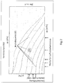
- the stored performance data L correlate with the different operating points P, such as those in the FIG. 2 are shown by way of example on a fan map.
- the fan characteristic map shows the characteristic curves as a function of the pressure and the air volume flow.
- the different operating points P are represented by a corresponding circle as a symbol at this operating point, the diameter being representative of the time period at this operating point. The longer the period over which a fan is operated at a certain operating point, the larger the illustrated diameter.
- An operating point is determined by the input of air flow and pressure increase.
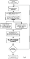
- FIG. 3 and 4 schematic flow diagrams are shown to variants of the method according to the invention.
- the method can be divided into a start and input phase, a calculation and selection phase and possibly an additional evaluation phase.
- the call is first made for the corresponding data processing software. This is followed by a selection of the data collection so that corresponding values and parameters can then be entered, such as the air density. With these values, the next step of the calculation and selection phase takes place, at the end of which an illustration of the selected fan (s) takes place. Thereafter, a product comparison and the analysis can be output by file in the evaluation phase. The process can be modified if necessary To run through parameters again. It is also possible to manually select individual fans and then perform the analysis.
- the input data can also be stored in a buffer and, if necessary, a calculation only after pressing a "Calculate Fan Array" input or prompt.
- the total energy consumption is determined for a fan over a period of operation to be set for a fan.
- the operating state of the fan to be set is carried out by the aforementioned inputs of several operating points P and their operating time via the input device 11, resulting in the total hours worked.
Landscapes
- Engineering & Computer Science (AREA)
- General Engineering & Computer Science (AREA)
- Physics & Mathematics (AREA)
- Theoretical Computer Science (AREA)
- Mechanical Engineering (AREA)
- Computer Hardware Design (AREA)
- Evolutionary Computation (AREA)
- Geometry (AREA)
- General Physics & Mathematics (AREA)
- Structures Of Non-Positive Displacement Pumps (AREA)
- Control Of Positive-Displacement Air Blowers (AREA)
Claims (16)
- Dispositif de simulation réalisé pour la détermination et la sélection d'une turbomachine ou d'un groupe de turbomachines (V1, ..., Vn), en particulier des ventilateurs pour une installation aéraulique avec des états de fonctionnement à changement dynamique, qui dispose/disposent dans au moins une grandeur détectable, une valeur optimisée concernant cette grandeur, sélectionnée parmi un nombre de n turbomachines (V1, ..., Vn), avec :a. un dispositif d'affichage (10) et un dispositif de saisie (11) pour la saisie de paramètres, en particulier de paramètres liés au fonctionnement (Pb) et/ou de paramètres liés à la turbomachine (Pm) ;b. une mémoire de données (20), dans laquelle une pluralité de données de performance (L) spécifiques au fonctionnement et/ou spécifiques à la turbomachine est enregistrée pour un nombre de turbomachines (V1, ..., Vn),c. un module de simulation d'installation (AS) avec des paramètres à réglage variable, lesquels représentent des états de système à changement dynamique sur une période de temps T d'une installation, dans lequel les paramètres correspondent à des paramètres de fonctionnement et/ou à des paramètres d'installation à changement dynamique et/ou à un nombre n' de turbomachines (V1, ..., Vn) actives sélectionné parmi n turbomachines (V1, ..., Vn) d'une installation,d. un opérateur de sélection (30), qui sélectionne parmi les données liées à la turbomachine enregistrées dans la mémoire de données (20) en fonction des paramètres saisis (Pb, Pn), une turbomachine déterminée ou un groupe de turbomachines déterminées (V1, ...., Vn) sélectionnées parmi les turbomachines présentes, qui sont déposées dans la mémoire de données (20), conformément à un algorithme de sélection en tenant compte d'états de fonctionnement dynamiques, en particulier à pondération temporelle dans l'intervalle de temps T, ete. affiche la sélection sur le dispositif d'affichage (10).
- Dispositif de simulation selon la revendication 1, caractérisé en ce que l'opérateur de sélection (30) lors de la sélection d'un groupe de n turbomachines (V1, ..., Vn) avec l'au moins un paramètre de fonctionnement nécessaire, tient aussi compte de l'état de fonctionnement, dans lequel un nombre n' des n turbomachines (V1, ..., Vn) ne sont pas actives ou présentent un dérangement.
- Dispositif de simulation selon la revendication 2, caractérisé en ce que l'opérateur de sélection (30) lors de la sélection d'un groupe de n turbomachines (V1, ..., Vn) tient aussi compte de l'état de fonctionnement, dans lequel le nombre n' de turbomachines (V1, ..., Vn) est traversé vers l'arrière dans le sens contraire à la direction d'écoulement conformément à l'utilisation des n' turbomachines (V1, ..., Vn) concernées.
- Dispositif de simulation selon la revendication 1, caractérisé en ce que le dispositif de simulation (1) présente en outre un opérateur de calcul (40), qui détermine à partir des paramètres (Pb, Pm) une valeur de sélection (S) correspondant à la grandeur à optimiser, qui est utilisée dans l'étape d) lors de la sélection.
- Dispositif de simulation selon la revendication 1 ou 2, caractérisé en ce que les données de performance enregistrées (L) sont enregistrées pour différents points de fonctionnement (P) et/ou états de fonctionnement de la/des turbomachine/s (V1, ..., Vn).
- Dispositif de simulation selon l'une quelconque des revendications précédentes, caractérisé en ce que la sélection dans l'étape d) de la revendication 1 concernant au moins la consommation d'énergie, un comportement sonore ou une autre grandeur dépendant des points de fonctionnement (P) de la ou des turbomachine/s (V1, ..., Vn) a lieu.
- Dispositif de simulation selon l'une quelconque des revendications précédentes, caractérisé en ce que le dispositif de simulation présente un champ de données pour l'enregistrement ou la saisie d'une valeur de consigne (S) d'une grandeur et cette valeur de consigne (S) est utilisée en tant que valeur limite supérieure ou inférieure lors de la détermination de la valeur de sélection (SW).
- Dispositif de simulation selon l'une quelconque des revendications précédentes, caractérisé en ce qu'un opérateur de détermination d'énergie (50) est prévu en outre, lequel détermine lors d'une saisie de paramètres liés au fonctionnement (Pb) une valeur d'énergie ou une valeur équivalente à une consommation d'énergie prévue à partir des données de performance (L) et des paramètres liés au fonctionnement (Pb) pour les turbomachines (V1, ..., Vn) sélectionnées et l'affiche sur le dispositif d'affichage (10).
- Dispositif de simulation selon au moins une des revendications précédentes, caractérisé en ce qu'une unité de génération d'image est prévue, laquelle représente les paramètres liés au fonctionnement (Pb) saisis et/ou paramètres liés à la turbomachine (Pm) en tant que vues graphiques et/ou symboles, en particulier de différente taille, en particulier en tant que cercles de différents diamètres sur l'unité d'affichage (10).
- Dispositif de simulation selon l'une quelconque des revendications précédentes, caractérisé en ce qu'au moins les lignes caractéristiques de ventilateur ou le champ de lignes caractéristiques de ventilateur est utilisé en tant que données de performance (L) spécifiques à la turbomachine, et peut être représenté de préférence sur l'unité d'affichage (10).
- Dispositif de simulation selon l'une quelconque des revendications précédentes, caractérisé en ce que le dispositif de simulation présente un logiciel de commande pour régler ou adapter l'état de fonctionnement des ou du groupe sélectionné de n turbomachines (V1, ..., Vn).
- Dispositif de simulation selon la revendication 11, caractérisé en ce que le logiciel de commande est réalisé pour régler, obtenir ou adapter un état de fonctionnement souhaité des ou du groupe sélectionné de n turbomachines (V1, ..., Vn) en tenant compte d'états de dérangement d'une ou plusieurs des turbomachines (V1, ..., Vn).
- Dispositif de simulation selon la revendication 11 ou 12, caractérisé en ce que le logiciel de commande est réalisé pour compenser un reflux dans n' turbomachines (V1, ..., Vn) non actives ou dérangées par activation d'une augmentation de performance des n-n' autres turbomachines (V1, ..., Vn).
- Dispositif de simulation selon la revendication 13, caractérisé en ce que les données de débit dans les n' turbomachines avec un reflux sont mesurées au moyen d'une unité de détection pour les transmettre au logiciel de commande pour l'adaptation ou le réglage de l'état de fonctionnement.
- Dispositif de simulation selon l'une quelconque des revendications précédentes, caractérisé en ce que le dispositif de simulation génère lors de la sélection d'une turbomachine ou d'un groupe de n turbomachines (V1, ..., Vn), une information de mise en service et/ou information de commande pour la mise en service et/ou le fonctionnement de la turbomachine ou du groupe de n turbomachines (V1, ..., Vn) et la met à disposition de préférence par le biais d'une interface de données filaire ou sans fil.
- Dispositif de simulation selon l'une quelconque des revendications précédentes, caractérisé en ce que l'installation est émise en tant que visualisation sur un écran ou un dispositif de sortie et lors de la modification des paramètres à réglage variable, lesquels représentent des états de système à changement dynamique sur une période de temps T d'une installation, les turbomachines (V1, ..., Vn) respectivement sélectionnées sont représentées dans l'installation simulée.
Applications Claiming Priority (2)
| Application Number | Priority Date | Filing Date | Title |
|---|---|---|---|
| DE102015118289.0A DE102015118289A1 (de) | 2015-10-27 | 2015-10-27 | Produktselektor |
| PCT/EP2016/075752 WO2017072154A1 (fr) | 2015-10-27 | 2016-10-26 | Dispositif de simulation et procédé de simulation |
Publications (2)
| Publication Number | Publication Date |
|---|---|
| EP3320216A1 EP3320216A1 (fr) | 2018-05-16 |
| EP3320216B1 true EP3320216B1 (fr) | 2019-02-27 |
Family
ID=57209455
Family Applications (1)
| Application Number | Title | Priority Date | Filing Date |
|---|---|---|---|
| EP16788077.2A Revoked EP3320216B1 (fr) | 2015-10-27 | 2016-10-26 | Dispositif de simulation et procédé de simulation |
Country Status (3)
| Country | Link |
|---|---|
| EP (1) | EP3320216B1 (fr) |
| DE (1) | DE102015118289A1 (fr) |
| WO (1) | WO2017072154A1 (fr) |
Families Citing this family (2)
| Publication number | Priority date | Publication date | Assignee | Title |
|---|---|---|---|---|
| US11773859B2 (en) * | 2018-02-05 | 2023-10-03 | Ziehl-Abegg Se | Method for optimizing the efficiency and/or the running performance of a fan or a fan arrangement |
| DE102019201412A1 (de) * | 2018-02-05 | 2019-08-08 | Ziehl-Abegg Se | Verfahren zum optimierten Betrieb eines Ventilators oder einer Ventilator-Anordnung |
Citations (7)
| Publication number | Priority date | Publication date | Assignee | Title |
|---|---|---|---|---|
| US5717865A (en) | 1995-09-25 | 1998-02-10 | Stratmann; William C. | Method for assisting individuals in decision making processes |
| JP2004246728A (ja) | 2003-02-14 | 2004-09-02 | Sharp Corp | ファン設計システムおよびファン設計方法 |
| US7110966B1 (en) | 2000-01-28 | 2006-09-19 | Carrier Corporation | Method for on-line selection of an air conditioning product |
| US20060225481A1 (en) | 2005-03-28 | 2006-10-12 | Sanyo Denki Co., Ltd. | Fan selection method and fan selection device |
| US7246087B1 (en) | 2000-01-10 | 2007-07-17 | General Electric Company | Method and apparatus for product selection assistance |
| WO2007102148A2 (fr) | 2006-03-06 | 2007-09-13 | Itzhak Barrabi Engineers And Advisors Ltd. | Systeme et procede de selection d'un systeme optimal de climatisation |
| US20140188425A1 (en) | 2012-12-28 | 2014-07-03 | Hon Hai Precision Industry Co., Ltd. | System and method for selecting fans for server cabinet |
-
2015
- 2015-10-27 DE DE102015118289.0A patent/DE102015118289A1/de not_active Withdrawn
-
2016
- 2016-10-26 EP EP16788077.2A patent/EP3320216B1/fr not_active Revoked
- 2016-10-26 WO PCT/EP2016/075752 patent/WO2017072154A1/fr not_active Ceased
Patent Citations (7)
| Publication number | Priority date | Publication date | Assignee | Title |
|---|---|---|---|---|
| US5717865A (en) | 1995-09-25 | 1998-02-10 | Stratmann; William C. | Method for assisting individuals in decision making processes |
| US7246087B1 (en) | 2000-01-10 | 2007-07-17 | General Electric Company | Method and apparatus for product selection assistance |
| US7110966B1 (en) | 2000-01-28 | 2006-09-19 | Carrier Corporation | Method for on-line selection of an air conditioning product |
| JP2004246728A (ja) | 2003-02-14 | 2004-09-02 | Sharp Corp | ファン設計システムおよびファン設計方法 |
| US20060225481A1 (en) | 2005-03-28 | 2006-10-12 | Sanyo Denki Co., Ltd. | Fan selection method and fan selection device |
| WO2007102148A2 (fr) | 2006-03-06 | 2007-09-13 | Itzhak Barrabi Engineers And Advisors Ltd. | Systeme et procede de selection d'un systeme optimal de climatisation |
| US20140188425A1 (en) | 2012-12-28 | 2014-07-03 | Hon Hai Precision Industry Co., Ltd. | System and method for selecting fans for server cabinet |
Also Published As
| Publication number | Publication date |
|---|---|
| WO2017072154A1 (fr) | 2017-05-04 |
| EP3320216A1 (fr) | 2018-05-16 |
| DE102015118289A1 (de) | 2017-04-27 |
Similar Documents
| Publication | Publication Date | Title |
|---|---|---|
| DE102009004385B4 (de) | Verfahren und Anordnung zum Überwachen einer Windenergieanlage | |
| EP3034955B1 (fr) | Procédé d'exécution d'un équilibrage hydraulique automatisé d'une installation de chauffage | |
| EP2580630B1 (fr) | Procédé de réglage du débit volumique d'un milieu chauffant et/ou réfrigérant au moyen d'échangeurs de chaleur ambiante d'une installation de chauffage ou de refroidissement | |
| DE102007022348A1 (de) | Einrichtung und Verfahren zur Störungsüberwachung | |
| EP3455500B1 (fr) | Procédé de régulation de ventilateurs et groupe de ventilateurs | |
| WO2011066823A2 (fr) | Procédé et dispositif permettant l'analyse de l'utilisation d'énergie lors du fonctionnement d'un système de production | |
| EP2085707A2 (fr) | Installation de chauffage et procédé destiné au fonctionnement d'une installation de chauffage | |
| DE102014205332A1 (de) | Verfahren zur Druckregelung in einem Versorgungsnetz, Vorrichtung sowie Versorgungsnetz | |
| DE102007030492A1 (de) | Gebäudemodellbasiertes prädiktives Regelverfahren zum Heizen eines begrenzten Systems | |
| EP3320216B1 (fr) | Dispositif de simulation et procédé de simulation | |
| DE102015217177A1 (de) | Transiente TBS-Berechnung des Gesamtfahrzeugs, Standardlastfälle und Nachheizen | |
| EP3655663A1 (fr) | Procédé de réglage d'au moins deux ventilateurs | |
| EP3167197B1 (fr) | Procédé de commande de la pression et la température d'un fluide dans une série de compresseurs cryogeniques | |
| EP3056957B1 (fr) | Procédé et dispositif de diagnostic destinés à la surveillance du fonctionnement d'un circuit régulateur | |
| EP3035281A1 (fr) | Analyse d'efficacite energetique d'une installation technique a partir de simulation et utilisation | |
| EP3486479A1 (fr) | Procédé de fonctionnement d'un parc éolien et parc éolien | |
| EP3366925A1 (fr) | Procédé de réglage fonctionnel d'un groupe motopompe ainsi que l'agencement d'un groupe motopompe et d'une électronique destiné à la mise en oeuvre dudit procédé | |
| EP2067080B1 (fr) | Procédé pour faire fonctionner une installation industrielle, et système de guidage correspondant | |
| EP3647899A1 (fr) | Procédé de fonctionnement d'une soupape, unité de commande électronique associée et entraînement de soupape | |
| EP3349078A1 (fr) | Dispositif de diagnostic et procédé de surveillance et/ou d'optimisation d'un dispositif de réglage | |
| DE102011075337A1 (de) | Verfahren und Vorrichtung zur Ansteuerung einer Anlage | |
| EP0770170B1 (fr) | Procede permettant d'etablir des diagnostics et de faire des previsions sur la tenue en service d'une installation de turbines | |
| DE202016103978U1 (de) | Ventilatorgruppe | |
| DE102007025727B4 (de) | Verfahren zur Steuerung eines Lüfters sowie Klimaanlage für ein Fahrzeug | |
| DE102021202255A1 (de) | Verfahren und System zur Handhabung eines Lüfters einer Dunstabzugsvorrichtung |
Legal Events
| Date | Code | Title | Description |
|---|---|---|---|
| STAA | Information on the status of an ep patent application or granted ep patent |
Free format text: STATUS: UNKNOWN |
|
| STAA | Information on the status of an ep patent application or granted ep patent |
Free format text: STATUS: THE INTERNATIONAL PUBLICATION HAS BEEN MADE |
|
| PUAI | Public reference made under article 153(3) epc to a published international application that has entered the european phase |
Free format text: ORIGINAL CODE: 0009012 |
|
| STAA | Information on the status of an ep patent application or granted ep patent |
Free format text: STATUS: REQUEST FOR EXAMINATION WAS MADE |
|
| 17P | Request for examination filed |
Effective date: 20180207 |
|
| AK | Designated contracting states |
Kind code of ref document: A1 Designated state(s): AL AT BE BG CH CY CZ DE DK EE ES FI FR GB GR HR HU IE IS IT LI LT LU LV MC MK MT NL NO PL PT RO RS SE SI SK SM TR |
|
| AX | Request for extension of the european patent |
Extension state: BA ME |
|
| GRAP | Despatch of communication of intention to grant a patent |
Free format text: ORIGINAL CODE: EPIDOSNIGR1 |
|
| STAA | Information on the status of an ep patent application or granted ep patent |
Free format text: STATUS: GRANT OF PATENT IS INTENDED |
|
| DAX | Request for extension of the european patent (deleted) | ||
| INTG | Intention to grant announced |
Effective date: 20180919 |
|
| GRAS | Grant fee paid |
Free format text: ORIGINAL CODE: EPIDOSNIGR3 |
|
| GRAA | (expected) grant |
Free format text: ORIGINAL CODE: 0009210 |
|
| STAA | Information on the status of an ep patent application or granted ep patent |
Free format text: STATUS: THE PATENT HAS BEEN GRANTED |
|
| DAV | Request for validation of the european patent (deleted) | ||
| AK | Designated contracting states |
Kind code of ref document: B1 Designated state(s): AL AT BE BG CH CY CZ DE DK EE ES FI FR GB GR HR HU IE IS IT LI LT LU LV MC MK MT NL NO PL PT RO RS SE SI SK SM TR |
|
| REG | Reference to a national code |
Ref country code: GB Ref legal event code: FG4D Free format text: NOT ENGLISH |
|
| REG | Reference to a national code |
Ref country code: CH Ref legal event code: EP |
|
| REG | Reference to a national code |
Ref country code: AT Ref legal event code: REF Ref document number: 1101777 Country of ref document: AT Kind code of ref document: T Effective date: 20190315 |
|
| REG | Reference to a national code |
Ref country code: IE Ref legal event code: FG4D Free format text: LANGUAGE OF EP DOCUMENT: GERMAN |
|
| REG | Reference to a national code |
Ref country code: DE Ref legal event code: R096 Ref document number: 502016003581 Country of ref document: DE |
|
| REG | Reference to a national code |
Ref country code: SE Ref legal event code: TRGR |
|
| REG | Reference to a national code |
Ref country code: NL Ref legal event code: MP Effective date: 20190227 |
|
| REG | Reference to a national code |
Ref country code: LT Ref legal event code: MG4D |
|
| PG25 | Lapsed in a contracting state [announced via postgrant information from national office to epo] |
Ref country code: NL Free format text: LAPSE BECAUSE OF FAILURE TO SUBMIT A TRANSLATION OF THE DESCRIPTION OR TO PAY THE FEE WITHIN THE PRESCRIBED TIME-LIMIT Effective date: 20190227 Ref country code: PT Free format text: LAPSE BECAUSE OF FAILURE TO SUBMIT A TRANSLATION OF THE DESCRIPTION OR TO PAY THE FEE WITHIN THE PRESCRIBED TIME-LIMIT Effective date: 20190627 Ref country code: NO Free format text: LAPSE BECAUSE OF FAILURE TO SUBMIT A TRANSLATION OF THE DESCRIPTION OR TO PAY THE FEE WITHIN THE PRESCRIBED TIME-LIMIT Effective date: 20190527 Ref country code: FI Free format text: LAPSE BECAUSE OF FAILURE TO SUBMIT A TRANSLATION OF THE DESCRIPTION OR TO PAY THE FEE WITHIN THE PRESCRIBED TIME-LIMIT Effective date: 20190227 Ref country code: LT Free format text: LAPSE BECAUSE OF FAILURE TO SUBMIT A TRANSLATION OF THE DESCRIPTION OR TO PAY THE FEE WITHIN THE PRESCRIBED TIME-LIMIT Effective date: 20190227 |
|
| PG25 | Lapsed in a contracting state [announced via postgrant information from national office to epo] |
Ref country code: BG Free format text: LAPSE BECAUSE OF FAILURE TO SUBMIT A TRANSLATION OF THE DESCRIPTION OR TO PAY THE FEE WITHIN THE PRESCRIBED TIME-LIMIT Effective date: 20190527 Ref country code: HR Free format text: LAPSE BECAUSE OF FAILURE TO SUBMIT A TRANSLATION OF THE DESCRIPTION OR TO PAY THE FEE WITHIN THE PRESCRIBED TIME-LIMIT Effective date: 20190227 Ref country code: RS Free format text: LAPSE BECAUSE OF FAILURE TO SUBMIT A TRANSLATION OF THE DESCRIPTION OR TO PAY THE FEE WITHIN THE PRESCRIBED TIME-LIMIT Effective date: 20190227 Ref country code: GR Free format text: LAPSE BECAUSE OF FAILURE TO SUBMIT A TRANSLATION OF THE DESCRIPTION OR TO PAY THE FEE WITHIN THE PRESCRIBED TIME-LIMIT Effective date: 20190528 Ref country code: LV Free format text: LAPSE BECAUSE OF FAILURE TO SUBMIT A TRANSLATION OF THE DESCRIPTION OR TO PAY THE FEE WITHIN THE PRESCRIBED TIME-LIMIT Effective date: 20190227 Ref country code: IS Free format text: LAPSE BECAUSE OF FAILURE TO SUBMIT A TRANSLATION OF THE DESCRIPTION OR TO PAY THE FEE WITHIN THE PRESCRIBED TIME-LIMIT Effective date: 20190627 |
|
| PG25 | Lapsed in a contracting state [announced via postgrant information from national office to epo] |
Ref country code: CZ Free format text: LAPSE BECAUSE OF FAILURE TO SUBMIT A TRANSLATION OF THE DESCRIPTION OR TO PAY THE FEE WITHIN THE PRESCRIBED TIME-LIMIT Effective date: 20190227 Ref country code: RO Free format text: LAPSE BECAUSE OF FAILURE TO SUBMIT A TRANSLATION OF THE DESCRIPTION OR TO PAY THE FEE WITHIN THE PRESCRIBED TIME-LIMIT Effective date: 20190227 Ref country code: AL Free format text: LAPSE BECAUSE OF FAILURE TO SUBMIT A TRANSLATION OF THE DESCRIPTION OR TO PAY THE FEE WITHIN THE PRESCRIBED TIME-LIMIT Effective date: 20190227 Ref country code: SK Free format text: LAPSE BECAUSE OF FAILURE TO SUBMIT A TRANSLATION OF THE DESCRIPTION OR TO PAY THE FEE WITHIN THE PRESCRIBED TIME-LIMIT Effective date: 20190227 Ref country code: IT Free format text: LAPSE BECAUSE OF FAILURE TO SUBMIT A TRANSLATION OF THE DESCRIPTION OR TO PAY THE FEE WITHIN THE PRESCRIBED TIME-LIMIT Effective date: 20190227 Ref country code: DK Free format text: LAPSE BECAUSE OF FAILURE TO SUBMIT A TRANSLATION OF THE DESCRIPTION OR TO PAY THE FEE WITHIN THE PRESCRIBED TIME-LIMIT Effective date: 20190227 Ref country code: EE Free format text: LAPSE BECAUSE OF FAILURE TO SUBMIT A TRANSLATION OF THE DESCRIPTION OR TO PAY THE FEE WITHIN THE PRESCRIBED TIME-LIMIT Effective date: 20190227 Ref country code: ES Free format text: LAPSE BECAUSE OF FAILURE TO SUBMIT A TRANSLATION OF THE DESCRIPTION OR TO PAY THE FEE WITHIN THE PRESCRIBED TIME-LIMIT Effective date: 20190227 |
|
| REG | Reference to a national code |
Ref country code: DE Ref legal event code: R026 Ref document number: 502016003581 Country of ref document: DE |
|
| PG25 | Lapsed in a contracting state [announced via postgrant information from national office to epo] |
Ref country code: SM Free format text: LAPSE BECAUSE OF FAILURE TO SUBMIT A TRANSLATION OF THE DESCRIPTION OR TO PAY THE FEE WITHIN THE PRESCRIBED TIME-LIMIT Effective date: 20190227 Ref country code: PL Free format text: LAPSE BECAUSE OF FAILURE TO SUBMIT A TRANSLATION OF THE DESCRIPTION OR TO PAY THE FEE WITHIN THE PRESCRIBED TIME-LIMIT Effective date: 20190227 |
|
| PLAX | Notice of opposition and request to file observation + time limit sent |
Free format text: ORIGINAL CODE: EPIDOSNOBS2 |
|
| PLBI | Opposition filed |
Free format text: ORIGINAL CODE: 0009260 |
|
| PLAN | Information deleted related to communication of a notice of opposition and request to file observations + time limit |
Free format text: ORIGINAL CODE: EPIDOSDOBS2 |
|
| 26 | Opposition filed |
Opponent name: PUNKER GMBH Effective date: 20191127 Opponent name: NICOTRA GEBHARDT GMBH Effective date: 20191127 Opponent name: ZIEHL-ABEGG SE Effective date: 20191127 |
|
| PLAB | Opposition data, opponent's data or that of the opponent's representative modified |
Free format text: ORIGINAL CODE: 0009299OPPO |
|
| PLAX | Notice of opposition and request to file observation + time limit sent |
Free format text: ORIGINAL CODE: EPIDOSNOBS2 |
|
| R26 | Opposition filed (corrected) |
Opponent name: PUNKER GMBH Effective date: 20191127 |
|
| PG25 | Lapsed in a contracting state [announced via postgrant information from national office to epo] |
Ref country code: TR Free format text: LAPSE BECAUSE OF FAILURE TO SUBMIT A TRANSLATION OF THE DESCRIPTION OR TO PAY THE FEE WITHIN THE PRESCRIBED TIME-LIMIT Effective date: 20190227 |
|
| PG25 | Lapsed in a contracting state [announced via postgrant information from national office to epo] |
Ref country code: MC Free format text: LAPSE BECAUSE OF FAILURE TO SUBMIT A TRANSLATION OF THE DESCRIPTION OR TO PAY THE FEE WITHIN THE PRESCRIBED TIME-LIMIT Effective date: 20190227 |
|
| REG | Reference to a national code |
Ref country code: CH Ref legal event code: PL |
|
| PLBB | Reply of patent proprietor to notice(s) of opposition received |
Free format text: ORIGINAL CODE: EPIDOSNOBS3 |
|
| PG25 | Lapsed in a contracting state [announced via postgrant information from national office to epo] |
Ref country code: LI Free format text: LAPSE BECAUSE OF NON-PAYMENT OF DUE FEES Effective date: 20191031 Ref country code: LU Free format text: LAPSE BECAUSE OF NON-PAYMENT OF DUE FEES Effective date: 20191026 Ref country code: CH Free format text: LAPSE BECAUSE OF NON-PAYMENT OF DUE FEES Effective date: 20191031 |
|
| REG | Reference to a national code |
Ref country code: BE Ref legal event code: MM Effective date: 20191031 |
|
| PG25 | Lapsed in a contracting state [announced via postgrant information from national office to epo] |
Ref country code: BE Free format text: LAPSE BECAUSE OF NON-PAYMENT OF DUE FEES Effective date: 20191031 |
|
| PG25 | Lapsed in a contracting state [announced via postgrant information from national office to epo] |
Ref country code: IE Free format text: LAPSE BECAUSE OF NON-PAYMENT OF DUE FEES Effective date: 20191026 |
|
| PG25 | Lapsed in a contracting state [announced via postgrant information from national office to epo] |
Ref country code: CY Free format text: LAPSE BECAUSE OF FAILURE TO SUBMIT A TRANSLATION OF THE DESCRIPTION OR TO PAY THE FEE WITHIN THE PRESCRIBED TIME-LIMIT Effective date: 20190227 |
|
| PG25 | Lapsed in a contracting state [announced via postgrant information from national office to epo] |
Ref country code: HU Free format text: LAPSE BECAUSE OF FAILURE TO SUBMIT A TRANSLATION OF THE DESCRIPTION OR TO PAY THE FEE WITHIN THE PRESCRIBED TIME-LIMIT; INVALID AB INITIO Effective date: 20161026 Ref country code: MT Free format text: LAPSE BECAUSE OF FAILURE TO SUBMIT A TRANSLATION OF THE DESCRIPTION OR TO PAY THE FEE WITHIN THE PRESCRIBED TIME-LIMIT Effective date: 20190227 |
|
| PG25 | Lapsed in a contracting state [announced via postgrant information from national office to epo] |
Ref country code: SI Free format text: LAPSE BECAUSE OF FAILURE TO SUBMIT A TRANSLATION OF THE DESCRIPTION OR TO PAY THE FEE WITHIN THE PRESCRIBED TIME-LIMIT Effective date: 20190227 |
|
| REG | Reference to a national code |
Ref country code: DE Ref legal event code: R103 Ref document number: 502016003581 Country of ref document: DE Ref country code: DE Ref legal event code: R064 Ref document number: 502016003581 Country of ref document: DE |
|
| RDAF | Communication despatched that patent is revoked |
Free format text: ORIGINAL CODE: EPIDOSNREV1 |
|
| PGFP | Annual fee paid to national office [announced via postgrant information from national office to epo] |
Ref country code: SE Payment date: 20211021 Year of fee payment: 6 Ref country code: DE Payment date: 20211020 Year of fee payment: 6 Ref country code: GB Payment date: 20211022 Year of fee payment: 6 Ref country code: AT Payment date: 20211019 Year of fee payment: 6 |
|
| PGFP | Annual fee paid to national office [announced via postgrant information from national office to epo] |
Ref country code: FR Payment date: 20211021 Year of fee payment: 6 |
|
| RDAG | Patent revoked |
Free format text: ORIGINAL CODE: 0009271 |
|
| STAA | Information on the status of an ep patent application or granted ep patent |
Free format text: STATUS: PATENT REVOKED |
|
| REG | Reference to a national code |
Ref country code: CH Ref legal event code: PL |
|
| REG | Reference to a national code |
Ref country code: FI Ref legal event code: MGE |
|
| 27W | Patent revoked |
Effective date: 20211209 |
|
| GBPR | Gb: patent revoked under art. 102 of the ep convention designating the uk as contracting state |
Effective date: 20211209 |
|
| PG25 | Lapsed in a contracting state [announced via postgrant information from national office to epo] |
Ref country code: MK Free format text: LAPSE BECAUSE OF FAILURE TO SUBMIT A TRANSLATION OF THE DESCRIPTION OR TO PAY THE FEE WITHIN THE PRESCRIBED TIME-LIMIT Effective date: 20190227 |
|
| REG | Reference to a national code |
Ref country code: AT Ref legal event code: MA03 Ref document number: 1101777 Country of ref document: AT Kind code of ref document: T Effective date: 20211209 |
|
| REG | Reference to a national code |
Ref country code: SE Ref legal event code: ECNC |