EP3320599B1 - Elektromagnetischer aktuator mit direktantrieb - Google Patents
Elektromagnetischer aktuator mit direktantrieb Download PDFInfo
- Publication number
- EP3320599B1 EP3320599B1 EP16741561.1A EP16741561A EP3320599B1 EP 3320599 B1 EP3320599 B1 EP 3320599B1 EP 16741561 A EP16741561 A EP 16741561A EP 3320599 B1 EP3320599 B1 EP 3320599B1
- Authority
- EP
- European Patent Office
- Prior art keywords
- valve
- shaft
- rotor
- electromagnetic actuator
- duct
- Prior art date
- Legal status (The legal status is an assumption and is not a legal conclusion. Google has not performed a legal analysis and makes no representation as to the accuracy of the status listed.)
- Active
Links
Images









Classifications
-
- F—MECHANICAL ENGINEERING; LIGHTING; HEATING; WEAPONS; BLASTING
- F02—COMBUSTION ENGINES; HOT-GAS OR COMBUSTION-PRODUCT ENGINE PLANTS
- F02D—CONTROLLING COMBUSTION ENGINES
- F02D9/00—Controlling engines by throttling air or fuel-and-air induction conduits or exhaust conduits
- F02D9/08—Throttle valves specially adapted therefor; Arrangements of such valves in conduits
- F02D9/10—Throttle valves specially adapted therefor; Arrangements of such valves in conduits having pivotally-mounted flaps
- F02D9/1035—Details of the valve housing
- F02D9/104—Shaping of the flow path in the vicinity of the flap, e.g. having inserts in the housing
- F02D9/1045—Shaping of the flow path in the vicinity of the flap, e.g. having inserts in the housing for sealing of the flow in closed flap position, e.g. the housing forming a valve seat
-
- F—MECHANICAL ENGINEERING; LIGHTING; HEATING; WEAPONS; BLASTING
- F02—COMBUSTION ENGINES; HOT-GAS OR COMBUSTION-PRODUCT ENGINE PLANTS
- F02D—CONTROLLING COMBUSTION ENGINES
- F02D11/00—Arrangements for, or adaptations to, non-automatic engine control initiation means, e.g. operator initiated
- F02D11/06—Arrangements for, or adaptations to, non-automatic engine control initiation means, e.g. operator initiated characterised by non-mechanical control linkages, e.g. fluid control linkages or by control linkages with power drive or assistance
- F02D11/10—Arrangements for, or adaptations to, non-automatic engine control initiation means, e.g. operator initiated characterised by non-mechanical control linkages, e.g. fluid control linkages or by control linkages with power drive or assistance of the electric type
-
- F—MECHANICAL ENGINEERING; LIGHTING; HEATING; WEAPONS; BLASTING
- F02—COMBUSTION ENGINES; HOT-GAS OR COMBUSTION-PRODUCT ENGINE PLANTS
- F02D—CONTROLLING COMBUSTION ENGINES
- F02D9/00—Controlling engines by throttling air or fuel-and-air induction conduits or exhaust conduits
- F02D9/08—Throttle valves specially adapted therefor; Arrangements of such valves in conduits
- F02D9/10—Throttle valves specially adapted therefor; Arrangements of such valves in conduits having pivotally-mounted flaps
- F02D9/1035—Details of the valve housing
- F02D9/105—Details of the valve housing having a throttle position sensor
-
- F—MECHANICAL ENGINEERING; LIGHTING; HEATING; WEAPONS; BLASTING
- F02—COMBUSTION ENGINES; HOT-GAS OR COMBUSTION-PRODUCT ENGINE PLANTS
- F02D—CONTROLLING COMBUSTION ENGINES
- F02D9/00—Controlling engines by throttling air or fuel-and-air induction conduits or exhaust conduits
- F02D9/08—Throttle valves specially adapted therefor; Arrangements of such valves in conduits
- F02D9/10—Throttle valves specially adapted therefor; Arrangements of such valves in conduits having pivotally-mounted flaps
- F02D9/1065—Mechanical control linkage between an actuator and the flap, e.g. including levers, gears, springs, clutches, limit stops of the like
-
- F—MECHANICAL ENGINEERING; LIGHTING; HEATING; WEAPONS; BLASTING
- F16—ENGINEERING ELEMENTS AND UNITS; GENERAL MEASURES FOR PRODUCING AND MAINTAINING EFFECTIVE FUNCTIONING OF MACHINES OR INSTALLATIONS; THERMAL INSULATION IN GENERAL
- F16K—VALVES; TAPS; COCKS; ACTUATING-FLOATS; DEVICES FOR VENTING OR AERATING
- F16K1/00—Lift valves or globe valves, i.e. cut-off apparatus with closure members having at least a component of their opening and closing motion perpendicular to the closing faces
- F16K1/16—Lift valves or globe valves, i.e. cut-off apparatus with closure members having at least a component of their opening and closing motion perpendicular to the closing faces with pivoted closure-members
- F16K1/18—Lift valves or globe valves, i.e. cut-off apparatus with closure members having at least a component of their opening and closing motion perpendicular to the closing faces with pivoted closure-members with pivoted discs or flaps
- F16K1/22—Lift valves or globe valves, i.e. cut-off apparatus with closure members having at least a component of their opening and closing motion perpendicular to the closing faces with pivoted closure-members with pivoted discs or flaps with axis of rotation crossing the valve member, e.g. butterfly valves
- F16K1/221—Lift valves or globe valves, i.e. cut-off apparatus with closure members having at least a component of their opening and closing motion perpendicular to the closing faces with pivoted closure-members with pivoted discs or flaps with axis of rotation crossing the valve member, e.g. butterfly valves specially adapted operating means therefor
-
- F—MECHANICAL ENGINEERING; LIGHTING; HEATING; WEAPONS; BLASTING
- F16—ENGINEERING ELEMENTS AND UNITS; GENERAL MEASURES FOR PRODUCING AND MAINTAINING EFFECTIVE FUNCTIONING OF MACHINES OR INSTALLATIONS; THERMAL INSULATION IN GENERAL
- F16K—VALVES; TAPS; COCKS; ACTUATING-FLOATS; DEVICES FOR VENTING OR AERATING
- F16K31/00—Actuating devices; Operating means; Releasing devices
- F16K31/02—Actuating devices; Operating means; Releasing devices electric; magnetic
- F16K31/04—Actuating devices; Operating means; Releasing devices electric; magnetic using a motor
- F16K31/041—Actuating devices; Operating means; Releasing devices electric; magnetic using a motor for rotating valves
- F16K31/043—Actuating devices; Operating means; Releasing devices electric; magnetic using a motor for rotating valves characterised by mechanical means between the motor and the valve, e.g. lost motion means reducing backlash, clutches, brakes or return means
-
- H—ELECTRICITY
- H02—GENERATION; CONVERSION OR DISTRIBUTION OF ELECTRIC POWER
- H02K—DYNAMO-ELECTRIC MACHINES
- H02K1/00—Details of the magnetic circuit
- H02K1/06—Details of the magnetic circuit characterised by the shape, form or construction
- H02K1/22—Rotating parts of the magnetic circuit
- H02K1/28—Means for mounting or fastening rotating magnetic parts on to, or to, the rotor structures
- H02K1/30—Means for mounting or fastening rotating magnetic parts on to, or to, the rotor structures using intermediate parts, e.g. spiders
-
- H—ELECTRICITY
- H02—GENERATION; CONVERSION OR DISTRIBUTION OF ELECTRIC POWER
- H02K—DYNAMO-ELECTRIC MACHINES
- H02K7/00—Arrangements for handling mechanical energy structurally associated with dynamo-electric machines, e.g. structural association with mechanical driving motors or auxiliary dynamo-electric machines
- H02K7/003—Couplings; Details of shafts
-
- F—MECHANICAL ENGINEERING; LIGHTING; HEATING; WEAPONS; BLASTING
- F02—COMBUSTION ENGINES; HOT-GAS OR COMBUSTION-PRODUCT ENGINE PLANTS
- F02M—SUPPLYING COMBUSTION ENGINES IN GENERAL WITH COMBUSTIBLE MIXTURES OR CONSTITUENTS THEREOF
- F02M26/00—Engine-pertinent apparatus for adding exhaust gases to combustion-air, main fuel or fuel-air mixture, e.g. by exhaust gas recirculation [EGR] systems
- F02M26/52—Systems for actuating EGR valves
- F02M26/53—Systems for actuating EGR valves using electric actuators, e.g. solenoids
- F02M26/54—Rotary actuators, e.g. step motors
-
- F—MECHANICAL ENGINEERING; LIGHTING; HEATING; WEAPONS; BLASTING
- F02—COMBUSTION ENGINES; HOT-GAS OR COMBUSTION-PRODUCT ENGINE PLANTS
- F02M—SUPPLYING COMBUSTION ENGINES IN GENERAL WITH COMBUSTIBLE MIXTURES OR CONSTITUENTS THEREOF
- F02M26/00—Engine-pertinent apparatus for adding exhaust gases to combustion-air, main fuel or fuel-air mixture, e.g. by exhaust gas recirculation [EGR] systems
- F02M26/65—Constructional details of EGR valves
- F02M26/70—Flap valves; Rotary valves; Sliding valves; Resilient valves
Definitions
- the invention relates to the field of electrical drive systems and more particularly to electromagnetic actuators intended to drive in rotation and in direct drive a mobile element belonging to a complementary mechanical system such as valves involved in the regulation of fluid circulation. for industrial applications, particularly automotive.
- connection between the movable part of the actuator and the specific member driven in rotation is traditionally made by means of a coupling shaft carrying out the transmission of the movement.
- the moving part of the actuator comprises its own means of guiding by bearing to ensure the quality of the positioning
- the specific driven member also comprises its own guiding means, in particular by bearing.
- the invention relates to the particular field of motorized valves.
- These valves consisting mainly of a pipe of substantially tubular shape in which there is a shutter valve capable of closing the pipe more or less, are present in many industrial applications, in particular automotive, where they are involved in the regulation of fluid , essentially at the air loop of the combustion engine on the intake side and on the exhaust side.
- the shutter valve is linked via a transmission shaft to an electromagnetic-type actuator designed to move and correctly position the valve in the duct between a first extreme position corresponding to maximum opening of the duct and a second extreme position corresponding to closing maximum of the duct, with a given level of tightness.
- patents WO9211686 and WO2007012711 describe a single-phase electromagnetic actuator intended to move a moving member over a limited stroke, comprising a wound stator structure and a moving member with a permanent magnet.
- the moving member is provided with a coupling shaft made integral by force-fitting the end of the shaft into the ferromagnetic part of the moving member.
- the patent application WO2014072605 claims a motorized valve combining an electromagnetic actuator according to the patents WO9211686 and WO2007012711 to a plastic overmolding material forming at least in part the tubing of the valve and partly secured to the actuator, the shutter valve being carried and positioned by the axis of the actuator.
- the coupling shaft of the actuator is at a first end rigidly secured to the rotor of the actuator, it carries at its second end in a rigid manner by means of fixing screws the closing valve collaborating with the conduit.
- the coupling shaft is only guided on its upper part, above the valve, it is not guided on its part lower, below the valve.
- the relative axial positioning between the valve and the tubing is dependent on the manufacturing tolerances of the shaft, the tubing, the actuator and the assembly methods, in particular the force fitting length of the coupling shaft in the rotor of the actuator and the fixing by threaded elements of the valve on the shaft. Clearances then appear in the closed position on the upper or lower parts of the valve between the tubing and the valve, severely degrading the sealing performance of the valve required by the application.
- the absence of shaft guide recovery coupling in its lower part, under the valve very strongly stresses the guides in its upper part: the significant forces induced by this cantilever phenomenon cause substantial friction which reduces the performance and efficiency of the actuator and which, in the long term, can destroy these guides.
- the absence of guide recovery also limits the rigidity of the maintenance of the valve in the duct, which strongly favors leaks under the valve, following the deformation by bending of the coupling shaft and its guides under the effect the pressure exerted in the closed position on the valve.
- This shaft is guided by several bearings located in the actuator and in the valve, the actuator and the valve here being two distinct components interconnected rigidly by screws.
- This type of assembly thus creates a hyperstatic connection causing significant stresses on the guides when the actuator and the valve are not perfectly and rigorously aligned or when the force fitting of the control shaft in the rotor of the actuator is not performed with a perfect beat.
- Other solutions proposed in this same patent consist in integrating an additional bearing provided at the lower end of the shaft under the shutter valve, which further increases this problem.
- valve which must collaborate with the tubing is rigidly fixed to the end of the shaft, the shaft being itself rigidly fixed to the rotor of the actuator, the actuator itself being attached and rigidly fixed to the valve by the screws.
- the positioning of the valve in the duct is then imprecise and clearances favoring leaks appear in the upper and lower zones of the valve.
- connection means creating a mechanical decoupling similar to a universal joint between the control axis and the pivot axis of the shutter.
- this solution has many drawbacks, in particular the necessary presence of two separate axes, one in the actuator and one in the valve, linked together by the introduction of an additional part which performs the decoupling but which severely complicates the movement transmission chain: the end of the two axes must integrate specific levers whose end is spherical, the manufacturing and assembly tolerances of the additional part as well as the size necessary for its integration and its mounting between the two axes increases the cost, the space required and reduces the quality of the transmission, in particular by the appearance of games resulting from the wear of this additional part at the level of the spherical ends.
- Other generic rotary electromagnetic actuators are described in the documents JP 2001 352701 A , WO 2004/084376 A1 and DE 10 2008 018460 A1 .
- the object of the invention is thus to respond to the problems set out above by proposing a direct drive actuator for motorized valves not only making it possible to solve the problems of hyperstatism but also to guarantee precise positioning of the specific organ to be controlled in minimum size and with an improved level of reliability.
- the invention relates to a rotary electromagnetic actuator having an axis of rotation, comprising a fixed stator and a rotor movable around said axis, said rotor driving via a transmission shaft a single external member connected to said shaft, characterized in that the connection between said rotor and said shaft is ensured by a mechanical connection means combining a finger ball joint type connection and a degree of freedom in axial translation.
- said mechanical connection means is disc-shaped, it consists of a central part with high isotropic rigidity secured to the transmission shaft, a peripheral part with high tangential rigidity connected to said rotor and said central part and said peripheral part are linked via n arms 425 extending radially, each arm 425 having tangential and high radial stiffness, each arm 425 having low axial stiffness, n being ⁇ 2, the ratio of high tangential stiffness and low axial stiffness being ⁇ 10, the ratio of high radial stiffness and low axial stiffness being ⁇ 2.5.
- said mechanical connection means is constituted by an overmolding plastic material secured to the end of said drive shaft, said overmolding extending as far as the rotor.
- said mechanical connection means comprises a metal insert between said overmolding and said transmission shaft.
- the mechanical connection means comprises a mobile magnetic target capable of interacting with a sensitive receiver element, fixed with respect to said target, to supply an angular position signal.
- the magnetic target is produced by bi-injection or overmolding of said mechanical connection means.
- said magnetic target is attached and fixed by gluing on said mechanical connection means.
- said actuator comprises a means for returning to the reference position in the form of a magnetic track integral with said stator and capable of interacting without contact with said rotor to return said control shaft to a position predetermined by the intermediary of said mechanical connection means, when said stator is no longer supplied with energy.
- the invention also relates to a method for assembling an electromagnetic actuator according to the invention and comprising at least two steps, a first step consisting in integrating said rotor with said stator and a second step consisting in inserting said shaft equipped with said connecting means mechanical through said rotor and said stator.
- the method according to the invention may comprise a third step consisting in fixing to said stator a cover comprising said sensitive receiving element.
- the invention also relates to a motorized valve comprising an electromagnetic actuator according to the invention and composed of a pipe and a valve capable of closing said pipe.
- the transmission shaft is guided by only two bearings arranged on either side of said valve in the zone of the duct.
- said bearings form connections of the annular linear type with said transmission shaft.
- the lower bearing opposite the actuator, consists of a stud erect with respect to the inner wall of the duct, and cooperating with a complementary housing provided in the valve.
- said stud has a hemispherical head capable of forming with said complementary housing a connection of the ball-and-socket type or of the annular linear type.
- the inner surface of said duct has a localized zone around said stud having a frustoconical or sloping shape capable of naturally evacuating, under the effect of gravity, the polluting particles likely to accumulate near said stud.
- the upper guide bearing of said valve provided between said transmission shaft and said stator is a bearing embedded in the plastic body of said duct, said bearing being sealed by a seal surrounding said shaft.
- valve is surrounded by a peripheral seal extending over the two annular branches able to bear against two shoulders provided on the inner wall of said duct, and on the two transverse end surfaces surrounding the shaft passages .
- the invention also relates to a method for assembling a motorized valve comprising at least three steps, a first step consisting in integrating said rotor into said valve, a second step consisting in integrating said valve in said pipe and a third step consisting in inserting said transmission shaft equipped with said mechanical connection means through said valve.
- this method comprises a fourth step consisting in attaching to said valve a cover comprising said sensitive receiving element.
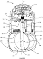
- the figure 1 shows a three-quarter view in partial section of a direct-drive electromagnetic actuator 100 according to the prior art.
- the electromagnetic actuator 100 comprises a fixed stator assembly 107 consisting of several ferromagnetic poles 112 surrounded by a coil 111 and connected to each other by a ferromagnetic base 110, the stator assembly 107 being overmoulded with a plastic material 113.
- the actuator 100 also comprises a rotor assembly 114 movable in rotation composed of a ferromagnetic yoke 102 carrying a multipolar permanent magnet 104.
- the rotor 114 also comprises a transmission shaft 106 force-fitted into the yoke 102 at the level of a specific zone 103 providing a recessed type connection, the lower end 109 of the shaft 106 being adapted according to the member to be controlled.
- a magnetic target 101 in the form of a permanent magnet is also fixed to the rotor 114 at the level of the yoke 102. This magnetic target 101 collaborates with a sensitive element 115 of the cover 117 capable of detecting the actual position of the rotor 114 relative to the stator 107
- the cover 117 is made of plastic material 116 and comprises an electrical interface 118, the cover 117 is fixed by gluing or by welding to the stator 107 via the plastic overmolding 113.
- the rotor 114 collaborates with the stator 107 by means of a thrust ball bearing 105 providing a support-plan type connection and eliminating 3 degrees of freedom between the yoke 102 and the plastic overmolding 113, thus taking up the forces of attraction under the effect of the permanent magnet 104 and the coils 111 and allowing relative rotation with minimum friction.
- the rotor 114 also collaborates with the stator 107 by means of an adjusted plain bearing 108 producing a sliding pivot type connection and eliminating 4 degrees of freedom between the transmission shaft 106 and the plastic overmoulding 113.
- the figure 2 shows a three-quarter view in partial section of a motorized valve 300 driven by a direct drive actuator 100 according to the prior art.
- the actuator 100 consists of a fixed stator assembly 107, a mobile rotor assembly 114 and a cover 117, the stator 107 and the rotor 114 being in hyperstatic pivot connection as described on the figure 1 .
- the plastic overmolding 113 of the stator 107 comprises, in a zone located under the fitted slide bearing 108, a duct 200 of tubular shape and oriented along the straight line (d2).
- the transmission shaft 106 has at its lower end 109 a specific shape capable of receiving and carrying rigidly (by screws not shown in the figure) a shutter valve 202 capable of opening the pipe 200 to a greater or lesser extent according to its relative angular position.
- a shutter valve 202 capable of opening the pipe 200 to a greater or lesser extent according to its relative angular position.
- the valve 202 collaborates and comes into contact with the inner surface 201 of the duct 200 to ensure closure with a given level of tightness, the valve 202 being driven in rotation by means of the transmission shaft 106 secured to the rotor 114 at the level of the connection 103.
- the axial positioning along the line (d1) of the valve 202, and therefore the level of sealing achieved, relative to the inner surface 201 of the duct 200 depends of the entire chain of dimensions involving respectively the distance of the plastic overmolding 113 between the straight line (d2) and the support of the ball bearing 105, the thickness of the ball bearing 105, the fitting length of the shaft 106 between link 103 and its lower end, the length of shaft 106 between its lower end and the specific fixing area 109 of valve 202, the precision of the fixing of valve 202 on part 109 of shaft 106 , the outside diameter of the valve 202.
- Non-functional and penalizing games resulting from the stacking of all the tolerances of the chain of dimensions then appear at the level of the upper 204 or lower part 203 between the valve 202 and the inner diameter 201 of the pipe 200, severely limiting the level of waterproofing.
- the transmission shaft 106 is floating in the duct 200 and cantilever the valve 202: its lower end is not taken up or guided in the duct 200 at the level of the lower zone 203 in order to avoid further increase the degree of hyperstatism of its guidance.
- the forces induced by the pressure of the gases on the valve 202 in a direction parallel to the axis (d2) will then friction stress and over-constrain the guiding of the shaft 106, in particular at the level of the sliding bearing adjusted 108 and thrust ball bearing 105.
- the play present in the zone lower 203 will thus be increased, following the bending by elastic deformation of the transmission shaft 106 and of the fitted plain bearing 108, further reducing the sealing performance.
- the picture 3 shows a three-quarter view in partial section of a preferred embodiment of an electromagnetic actuator 400 with direct drive according to the invention.
- the electromagnetic actuator 400 comprises a fixed stator assembly 407 consisting of several ferromagnetic poles 412 surrounded by a winding 411 and interconnected by a ferromagnetic base 410, the stator assembly 407 being molded with a plastic material 413.
- 400 also comprises a rotor assembly 414 mobile in rotation composed of a ferromagnetic yoke 402 carrying a multipolar permanent magnet 404, the rotor 414 being linked to the stator 407 by means of a thrust ball bearing 405 taken between the yoke 402 and the plastic overmolding 413.
- the actuator 400 also comprises a cover 417 made of plastic material 416 and fixed to the stator 407 via the plastic overmolding 413, the cover 417 being provided with an electrical interface 418 in the form of a connector and a a sensitive element 415 for detecting the angular position.
- a transmission shaft 406 is also provided: it comprises at its lower end a specific shape 409 able to be linked to the application to be driven, it is secured at its upper end to a connecting element 419 via a recessed type connection 403 , made for example by plastic overmolding.
- the connecting element 419 is free relative to the cylinder head via a functional clearance 421 prohibiting any contact in order to avoid problems of hyperstatism.
- the connecting element 419 is provided with several rotational coupling means 422 capable of transmitting the rotational movement of the yoke 402 to the shaft 406 via the connection 403, the coupling means 422 also ensuring the positioning of the transmission shaft 406.
- the connecting element 419 also incorporates a magnetic target 401 capable of collaborating with the sensitive element 415 of the cover 417.
- the actuator 400 is provided with a position return system in the form of a a multipolar permanent magnet 420 fixed to the stator 407 at the level of the ferromagnetic poles 412, the fixed return magnet 420 collaborating with the mobile motor magnet 404 to create a return torque such as, for example, described in the patent EP0886875 .
- the transmission shaft 406 collaborates with the stator 407 at the level of a bearing 408 produced by the plastic overmolding 413 or by an attached bearing (not shown in the figure).
- the bearing 408 can be with a functional clearance prohibiting any contact between the transmission shaft 406 and the stator 407, the guiding of the the shaft 406 being in this case provided by the guide elements of the member to be controlled, the shaft 406 being secured to the member to be controlled; the bearing 408 can also be adjusted to guarantee correct centering with the stator 407, the bearing 408 being in this case one of the guiding elements of the member to be driven if the shaft 406 is integral with the member to be driven, a specific coupling system that may be necessary between the shaft 406 and the member to be driven if the member to be driven has its own guides.
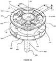
- the figure 4A shows an exploded detail view of a first embodiment of the connecting element 419 between the transmission shaft 406 and the rotor 414 of the direct-drive actuator 400 according to the invention.
- the connecting element 419 is preferably but not limited to plastic material, it is molded and rigidly fixed to the transmission shaft 406 via a central part 423 secured to the end of the shaft 406. This central part 423 also incorporates a surface 421 penetrating the center of the yoke 402 but never coming into contact, and a magnetic target 401 made by bi-injection or overmolding.
- the connecting element 419 also comprises a peripheral zone 424 having a high tangential rigidity relative to the axis (d3).
- This outer annular portion 424 is equipped with coupling means in the form of clutch pins 422 collaborating with complementary housings 426 belonging to the cylinder head 402 in order to carry out a transmission of the engine torque from the rotor 414 to the transmission shaft 406 in eliminating any relative movement between the yoke 402 and the connecting element 419 in a direction tangential to the axis (d3).
- the connecting element 419 also comprises connecting arms 425 making it possible to secure the peripheral zone 424, connected in rotation to the cylinder head 402, to the central zone 423 rigidly connected to the transmission shaft 406. Radially to the axis ( d3), the connecting arms 425 have an effective length D, a section of width L and of thickness E.
- the connecting element 419, via the peripheral zone 424, the connecting arms 425 and the central part 423 creates a play-free connection, based on the elasticity and rigidity of its various constituent parts, at 3 degrees of freedom between the rotor 414 and the transmission shaft 406.
- This center connection ⁇ is of the finger ball joint type with an additional translation: it thus allows 2 degrees of freedom in rotation around the axes (d4) and (d5) and a degree of freedom in translation along the axis (d3).
- the figure 4B shows an exploded detail view in partial section of a second embodiment of the connecting element 419 between the transmission shaft 406 and the rotor 414 of the direct drive actuator 400 according to the invention.
- the connecting element 419 is made of plastic material, it overmolds a metal insert 427 which is rigidly fixed by fitting in force on the upper end of the transmission shaft 406.
- the insert 427 comprises a specific zone 421b having grooves or knurling in order to ensure good cohesion with the connecting element 419, it also incorporates a surface 421a penetrating into the center of the yoke 402 but without ever coming into contact, and a magnetic target 401 attached and glued.
- the connecting element 419 also comprises a peripheral zone 424 having a high tangential rigidity relative to the axis (d3).
- This outer annular portion 424 is equipped with coupling means in the form of clutch pins 422 collaborating with complementary housings 426 belonging to the cylinder head 402 in order to carry out a transmission of the engine torque from the rotor 414 to the transmission shaft 406 in eliminating any relative movement between the yoke 402 and the connecting element 419 in a direction tangential to the axis (d3).
- the connecting element 419 also comprises connecting arms 425 making it possible to secure the peripheral zone 424 connected in rotation to the yoke 402 of the central zone 423 overmolding the insert 427 rigidly fixed to the transmission shaft 406.
- connection 425 perform the same function and are dimensioned as described on the figure 4A .
- the connecting element 419, via the peripheral zone 424, the connecting arms 425, the central part 423 and the insert 427 creates a connection without play, relying on the elasticity and the rigidity of its different constituent parts, with 3 degrees of freedom between the rotor 414 and the transmission shaft 406.
- This center connection ⁇ is of the ball and socket type with an additional translation: it thus allows 2 degrees of freedom in rotation around the axes ( d4) and (d5) and a degree of freedom in translation along the axis (d3).
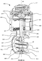
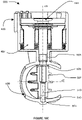
- the figure 5 shows a partial sectional view of a first embodiment of a motorized valve 600 driven by a direct-drive electromagnetic actuator 400 according to the invention.
- the actuator 400 consists of a stator 407, a cover 417 and a rotor 414, it comprises a transmission shaft 406 linked to the rotor 414 via an element connection 419.
- the stator 407 includes a return system in position 420, it is overmolded with a plastic material 413 in contact with the cover 417 and extending over the lower part of the actuator 400 to form a tubular pipe 500 , the inner surface 501 of the pipe 500 collaborating with a shutter valve 502 via a sealing element 505 fixed on the periphery of the valve 502.
- the shutter valve 502 is driven in rotation by the transmission shaft 406 which crosses it entirely: the shaft 406 is provided with a first specific surface 429 extending axially along the line (d6), a flat for example , collaborating with the 2 upper 507 and lower 508 passages of the shaft 406 through the valve 502 to drive and rotate it.
- the shaft 406 is also provided with a second specific surface 430 extending circumferentially along the line (d6), a groove for example, collaborating with the clips 509 of the valve 502 to ensure the axial retention of the transmission shaft 406 along the line (d6), the outer diameter of the valve 502 and of the sealing element 505 being adjusted to the diameter of the inner surface 501 of the pipe 500.
- This type of assembly makes it possible to guarantee an optimum relative positioning between the valve 502 and the surface 501 of the pipe 500, the positioning only depending on the manufacturing and adjustment tolerances of the valve 502 and of the surface 501, the valve 502 no longer being axially and directly positioned along the straight line (d6) by drive shaft 406.
- the transmission shaft 406 comprises a specific intermediate surface 428 in annular linear connection with a bearing 503, attached or directly produced by the overmolding 413, in the upper zone valve 502 belonging to conduit 500, this connection eliminating 2 degrees of freedom in translation in a first plane located above valve 502 and orthogonal to the right (d6).
- the bearing 503 incorporates a dynamic sealing element 506 between the shaft 406 and the duct 500 in order to prevent the fluid circulating in the duct 500 in the direction (d7) from rising in the actuator 400 in the direction (d6) .
- the transmission shaft 406 also comprises at its lower end a specific surface 431 in annular linear connection with a bearing 504, attached or directly produced by the overmolding 413 in the lower zone of the valve 502 belonging to the duct 500, this connection eliminating 2 degrees freedom in translation in a second plane located below the valve 502 and orthogonal to the line (d6).
- the clips 509 of the valve 502, fitted to the surface 501 of the valve 500, collaborating with the groove 430 of the shaft 406 remove 1 degree of freedom in translation along the straight line (d6).
- the resulting connection thus obtained between the control shaft 406 and the plastic molding 413 of the valve 600 is a connection with a single degree of freedom of the pivot type and isostatic in nature.
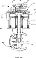
- the Figure 6A shows a partial sectional view of a second embodiment of a motorized valve 600 driven by a direct-drive electromagnetic actuator 400 according to the invention.
- the shutter valve 502 is driven in rotation by the transmission shaft 406: the shaft 406 is provided with a specific surface 429 extending axially along the line (d6), a flat for example, collaborating with the passage upper 507 of shaft 406 through valve 502 to drive and rotate it.
- valve 502 and of the sealing element 505 are adjusted to the diameter of the inner surface 501 of the pipe 500: this type of assembly makes it possible to guarantee optimum relative positioning between the valve 502 and the surface 501 of the pipe 500, the positioning only depending on the manufacturing tolerances and adjustment of the valve 502 and of the surface 501, the valve 502 no longer being axially and directly positioned along the line (d6) by the control shaft 406.
- the transmission shaft 406 comprises a specific intermediate surface 428 in annular linear connection or ball joint with a bearing 503, attached or directly produced by the overmoulding 413, in the upper zone of valve 502 belonging to conduit 500, this connection eliminating 2 degrees of freedom in translation in a first plane located above valve 502 and orthogonal to the line (d6) and possibly eliminating one degree of freedom in translation along the line (d6).
- the bearing 503 incorporates a dynamic sealing element 506 between the shaft 406 and the duct 500 in order to prevent the fluid circulating in the duct 500 in the direction (d7) from rising in the actuator 400 in the direction (d6) .
- the valve 600 also comprises a stud 510 emerging radially inside the pipe 500, the stud 510 being open and embedded from the outside in the pipe 500, the stud 510 being associated with an O-ring 512 to ensure sealing. .
- the hemispherical end 511 of the stud 510 cooperates with the bearing 513 at the level of the passage 508 of the valve 502 to form an annular linear connection or ball joint, this connection eliminating 2 degrees of freedom in translation in a second plane located below the valve 502 and orthogonal to the line (d6) and possibly eliminating a degree of freedom in translation along the line (d6).
- the movement and positioning by the rotor 414 of the valve 502 by means of the control shaft 406 is thus carried out in an isostatic and precise manner, without inducing over-stress on the guide elements 503 and 513 distributed in either side of valve 502.
- the figure 6B shows a partial sectional view of a third embodiment of a motorized valve 600 controlled by an electromagnetic actuator 400 with direct drive according to the invention.
- the valve 600 also comprises a stud 510 emerging radially inside the pipe 500, the stud 510 being non-emerging and embedded from the inside in the pipe 500.
- a niche 513 provided inside and in the center of the valve 502 at the level of its lower part 508 makes it possible to fully house the stud 510 in the valve 502 when inserting the valve 502 into the conduit 500 in one direction (d7).
- an assembly element (not shown in the figure) through the stator 407 of the actuator 400, through the upper bearing 503 of the valve 500 and through the upper part 507 of the valve 502 comes into contact on the upper part of stud 510 to embed it in the blind bore 514 of conduit 500 in one direction (d6).
- the hemispherical end 511 of the stud 510 cooperates with the bearing located in the lower part of the niche 513 at the level of the passage 508 of the valve 502 to form an annular linear connection or ball joint, this connection eliminating 2 degrees of freedom in translation in a second plane. located below the valve 502 and orthogonal to the line (d6) and possibly eliminating a degree of freedom in translation along the line (d6).
- the movement and positioning by the rotor 414 of the valve 502 by means of the control shaft 406 is thus carried out in an isostatic and precise manner, without inducing over-stress on the guide elements 503 and 513 distributed in either side of valve 502.
- the figure 7 shows a detailed view of a preferred embodiment of a shutter valve 502 of a motorized valve 600 controlled by an electromagnetic actuator 400 with direct drive according to the invention.
- the closure valve 502 preferably made of plastic, is associated with a sealing element 505 which can be produced by bi-injection, overmolding of the valve 502 or simply fixed by gluing, the element of sealing 505 preferably being a flexible material of the elastomer type.
- the sealing element 505 consists of two annular branches 515a-515b located at the periphery of the valve 502, each annular branch 515a and 515b being on a different face of the valve 502, the annular branches being provided to cooperate with the inner wall 501 of the duct 500 to seal in the closed position.
- the sealing element 505 also consists of two branches of substantially toroidal shapes 516a-516b arranged on the two transverse end surfaces surrounding the shaft passages 507 and 508, the branches 516a and 516b being provided to be in permanent contact with the inner surface 501 of the duct 500 with the aim of sealing in the closed position, with the aim of sealing the contact between the shafts and the duct, and with the aim of prohibiting particles pollutants from coming to agglomerate on the trees so as not to block the valve 502 in rotation.
- the two annular branches 515a-515b and the substantially toroidal branches 516a-516b are interconnected to form a sealing element 505 in one piece.
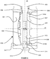
- the figure 8 shows a detail view in section of a preferred embodiment of the lower part of the conduit 500 of a motorized valve 600 controlled by an electromagnetic actuator 400 with direct drive according to the invention.
- the shutter valve 502 is equipped with a sealing element 505 of which only the branches 516a-516b located towards the shaft passages 507 and 508 are visible. These two branches 516a-516b are in permanent contact with the inner surface 501 of the duct 500: they thus effectively protect the shaft 406 and the stud 510 from any polluting particles that may come in and block the rotation of the valve 502.
- These two branches 516a-516b also participate in sealing the duct in the closed position insofar as they eliminate the leak paths which may be found in the upper and lower zone of the valve 502 at the level of the shaft passages 507-508.
- the transmission shaft 406 engages the valve 502 at the level of the passage 507, it causes it to rotate via a flat 429.
- the shaft 406 is guided by the valve 500 with a bearing 503 in contact with a specific surface 428 creating a connection of the linear annular or ball joint type, this connection being sealed by a dynamic seal 506, this seal being redundant, and therefore optional, with the sealing branch 516a of the valve 502.
- the lower part of the valve 502 is guided by a stud 510 fixed with the valve 500.
- the stud 510 is housed in the niche 513 of the valve 502.
- the assembly system (not shown in the figure) embeds the stud 510 in the blind bore 514 of the valve 500 through the bearing 503 and of the valve 502, the transmission shaft 406 not yet being inserted.
- the hemispherical end 511 of the stud 510 then cooperates with the lower part of the recess 513 to form a connection of the linear annular or ball joint type.
- the sealing branch 516b of the valve 502 is in permanent contact with the inner surface 501 of the valve 500
- This surface 501 also includes a zone 517 located around the sealing branch 516b, this zone 517 has a frustoconical or sloping shape capable of naturally evacuating under the effect of gravity the polluting particles likely to accumulate near the stud 510, the line (d6) being generally oriented vertically.
- the figure 9 shows a sectional view of a preferred embodiment of the conduit 500 of the motorized valve 600 in the closed position controlled by an electromagnetic actuator 400 with direct drive according to the invention.
- the inner surface 501 of the conduit 500 comprises two shoulders 518a-518b penetrating substantially radially in the direction of the axis (d7) of the conduit 500. These two shoulders provide a rigid stop to the valve 502 in the closed position and collaborate with the peripheral branches of sealing 515a-515b to sufficiently seal the closed position, the sealing branches 515a-515b respectively coming into contact on the shoulders 518a-518b.
- the figure 10A shows a sectional view of a preferred embodiment of a manufacturing phase of a motorized valve 600 controlled by an electromagnetic actuator 400 with direct drive according to the invention.
- This manufacturing phase corresponds to the overmolding operation of the stator 407 consisting of ferromagnetic poles 412 surrounded by a winding 411 and interconnected by a ferromagnetic base 410.
- the return element in position 420 is already integrated on the poles 412 at the level of the upper part, slightly recessed so as to be completely overmoulded.
- the plastic overmolding 413 can thus completely enclose the stator 407, in particular under the lower surface of the base 410.
- the plastic overmolding 413 will produce the bearing 408 of the actuator 400 and the conduit 500 of the motorized valve 600, the conduit 500 comprising an inner surface 501, a blind bore 514 and the radial shoulders 518b-518a.
- the plastic overmolding 413 thus performs the overmolding of the actuator 400 and the duct 500 in one piece and in a single operation: the plastic overmolding 413 thus allows the mechanical connection and precise relative positioning between these two elements.
- the figure 10B shows a sectional view of a preferred embodiment in a first assembly step of a motorized valve 600 driven by an electromagnetic actuator 400 with direct drive according to the invention.
- this first assembly step consists in integrating into the bearing 408 of the actuator 400 and in the direction (d6) an attached guide bearing 503 and an optional dynamic seal 506.
- This first step also consists in integrating the rotor 414 composed of a thrust ball bearing 405, a ferromagnetic yoke 402 and a permanent magnet 404.
- the motor tests of the actuator 400 are carried out, in particular the measurement of the motor torque when the winding 411 is energized, the measurement of the restoring torque resulting from the interaction between the motor magnet 404 and the return system 420 when the winding 411 is not powered and the measurement of the friction under load of the thrust bearing.
- the figure 10C shows a sectional view of a preferred embodiment in a second assembly step of a motorized valve 600 driven by an electromagnetic actuator 400 with direct drive according to the invention.
- this second assembly step consists of integrating into the duct 500 and in the direction (d7) a shutter valve 502 comprising a sealing element 505 and a stud 510 housed in a niche 513 of the valve 502.
- the assembly system (not shown in the figure) embeds the stud 510 in the blind bore 514 of the valve 500 through the rotor 414, the bearing 503 and the valve 502.
- the figure 10D shows a sectional view of a preferred embodiment in a third assembly step of a motorized valve 600 driven by an electromagnetic actuator 400 with direct drive according to the invention.
- this third assembly step consists of integrating in one direction (d6) a transmission shaft 406 which will be connected in rotation via a connecting element 419 to the rotor 414 and which will be connected in rotation via a flat 429 to the valve d shutter 502.
- the connecting element 419 includes a magnetic target 401.
- the figure 10E shows a sectional view of a preferred embodiment in a fourth assembly step of a motorized valve 600 driven by an electromagnetic actuator 400 with direct drive according to the invention.
- this fourth assembly step consists in integrating a cover 417 provided with an electrical interface 418.
- the cover 417 is fixed on the stator 407, it is also equipped with a sensitive element 415 collaborating with the magnetic target 401 for the detection of the angular position.
- the programming of the sensitive element 415 relative to the magnetic target 401 is carried out.
- the winding 411 of the stator 407 is supplied a first time in order to bring the valve 502 into the fully open position, this position is then programmed in the sensitive element 415; the power is supplied a second time or the power is cut to have the return torque in position, to bring the valve 502 into the fully closed position, this position is then programmed in the sensitive element 415.
Landscapes
- Engineering & Computer Science (AREA)
- General Engineering & Computer Science (AREA)
- Mechanical Engineering (AREA)
- Chemical & Material Sciences (AREA)
- Combustion & Propulsion (AREA)
- Power Engineering (AREA)
- Magnetically Actuated Valves (AREA)
- Electrically Driven Valve-Operating Means (AREA)
Claims (20)
- Drehbares Magnetstellwerk, das eine Drehachse 106 vorweist, umfassend einen feststehenden Stator (107) und einen Rotor (114), der um die Achse herum bewegbar ist, wobei der Rotor (114) durch eine einzige Übertragungswelle ein externes Bauteil antreibt, das mit der Welle verbunden ist, dadurch gekennzeichnet, dass die Verbindung zwischen dem Rotor (114) und der Welle durch ein mechanisches Verbindungsmittel (419) sichergestellt ist, das eine Verbindung einer Fingerkugelgelenkart und einen Freiheitsgrad in axialer Verschiebung kombiniert.
- Magnetstellwerk nach Anspruch 1, dadurch gekennzeichnet, dass das mechanische Verbindungsmittel scheibenförmig ist, dass es aus einem steifen isotropen Mittelteil, der mit der Übertragungswelle fest verbunden ist, einem steifen tangentialen Umfangsteil besteht, der mit dem Rotor (114) verbunden ist, und dadurch, dass der Mittelteil und der Umfangsteil durch n Arme (425) verbunden sind, die sich radial erstrecken, wobei jeder Arm (425) hohe Tangential- und Radialsteifheiten vorweist, jeder Arm (425) geringe Axialsteifheit vorweist, n ≥ 2 ist, das Verhältnis von der hohen Tangentialsteifheit zu der geringen Axialsteifheit ≥ 10 ist, das Verhältnis zwischen der hohen Radialsteifheit zu der geringen Axialsteifheit ≥ 2,5 ist.
- Magnetstellwerk nach Anspruch 1 oder 2, dadurch gekennzeichnet, dass das mechanische Verbindungsmittel aus einem Kunststoffmaterial besteht, das das Ende der Antriebswelle konfektioniert und mit diesem fest verbunden ist, wobei sich die Konfektionierung bis zu dem Rotor (114) erstreckt.
- Magnetstellwerk nach Anspruch 3, dadurch gekennzeichnet, dass das mechanische Verbindungsmittel einen Metalleinsatz zwischen der Konfektionierung und der Übertragungswelle aufweist.
- Magnetstellwerk nach einem der vorstehenden Ansprüche, dadurch gekennzeichnet, dass das mechanische Verbindungsmittel ein bewegbares magnetisches Ziel aufweist, das geeignet ist, um mit einem empfindlichen Empfangselement, das bezogen auf das Ziel feststehend ist, zum Bereitstellen eines Winkelpositionssignals zusammenzuwirken.
- Magnetstellwerk nach Anspruch 5, dadurch gekennzeichnet, dass das magnetische Ziel durch Doppeleinspritzung oder Konfektionierung des mechanischen Verbindungsmittels hergestellt ist.
- Magnetstellwerk nach Anspruch 5, dadurch gekennzeichnet, dass das magnetische Ziel durch Kleben an dem mechanischen Verbindungsmittel angebracht und befestigt ist.
- Magnetstellwerk nach einem der vorstehenden Ansprüche, dadurch gekennzeichnet, dass das Stellwerk ein Mittel eines Rückführens in eine Referenzposition in Form einer Magnetbahn umfasst, die mit dem Stator (107) fest verbunden und geeignet ist, um ohne Kontakt mit dem Rotor (114) zum Zurückbringen der Steuerungswelle in eine zuvor bestimmte Position durch das mechanische Verbindungsmittel zusammenzuwirken, wenn der Stator (107) nicht länger mit Energie versorgt wird.
- Verfahren zum Zusammenbauen eines Magnetstellwerks nach einem der vorstehenden Ansprüche, dadurch gekennzeichnet, dass es mindestens zwei Schritte umfasst, dass ein erster Schritt darin besteht, den Rotor (114) in den Stator (107) einzufügen, und dass ein zweiter Schritt darin besteht, die Welle, die mit dem mechanischen Verbindungsmittel ausgestattet ist, über den Rotor (114) und den Stator (107) einzusetzen.
- Verfahren nach Anspruch 9 zum Zusammenbauen eines Magnetstellwerks nach Anspruch 5, dadurch gekennzeichnet, dass es einen dritten Schritt aufweist, der darin besteht, an dem Stator (107) eine Abdeckung zu befestigen, die das empfindliche Empfangselement aufweist.
- Motorventil, umfassend ein Magnetstellwerk nach einem der Ansprüche 1 bis 8 und das aus einer Leitung und einer Klappe besteht, die geeignet ist, um die Leitung zu verschließen.
- Motorventil nach Anspruch 11, dadurch gekennzeichnet, dass die Übertragungswelle durch nur zwei Lager geführt wird, die auf beiden Seiten der Klappe in dem Leitungsbereich angeordnet sind.
- Motorventil nach Anspruch 12, dadurch gekennzeichnet, dass die Lager mit der Übertragungswelle Verbindungen einer linearen ringförmigen Art ausbilden.
- Motorventil nach Anspruch 13, dadurch gekennzeichnet, dass das untere Lager gegenüber dem Stellwerk aus einem bezogen auf die Innenwand der Leitung aufrechten Zapfen besteht, und mit einer komplementären Aufnahme zusammenwirkt, die in der Klappe vorgesehen ist.
- Motorventil nach Anspruch 14, dadurch gekennzeichnet, dass der Zapfen einen halbkugelförmigen Kopf vorweist, der geeignet ist, mit der komplementären Aufnahme eine Verbindung einer Kugelgelenkart oder der linearen ringförmigen Art auszubilden.
- Motorventil nach Anspruch 15, dadurch gekennzeichnet, dass die Innenoberfläche der Leitung um den Zapfen herum einen lokalisierten Bereich vorweist, der eine kegelstumpfförmige oder abschüssige Form besitzt, die geeignet ist, um unter der Wirkung der Schwerkraft die Schadstoffpartikel natürlich abzuführen, die imstande sind, sich in der Nähe des Zapfens anzusammeln.
- Motorventil nach einem der Ansprüche 12 bis 16, dadurch gekennzeichnet, dass das Lager der oberen Führung der Klappe, das zwischen der Übertragungswelle und dem Stator (107) vorgesehen ist, ein Lager ist, das in den Kunststoffmaterialkörper der Leitung eingebettet ist, wobei das Lager durch eine Dichtung abgedichtet ist, die die Welle umgibt.
- Motorventil nach einem der Ansprüche 12 bis 17, dadurch gekennzeichnet, dass die Klappe durch eine Umfangsdichtung umgeben ist, die sich über die zwei ringförmigen Schenkel erstreckt, die geeignet sind, um gegen zwei Schultern, die an der Innenwand der Leitung vorgesehen sind, und an den zwei queren Vorderoberflächen anzuliegen, die die Wellendurchgänge umgeben.
- Verfahren zum Zusammenbauen eines Motorventils nach einem der Ansprüche 11 bis 18, dadurch gekennzeichnet, dass es mindestens drei Schritte umfasst, dass ein erster Schritt darin besteht, den Rotor (114) in das Ventil einzufügen, und dass ein zweiter Schritt darin besteht, die Klappe in die Leitung einzufügen, und dass ein dritter Schritt darin besteht, die Übertragungswelle, die mit den mechanischen Verbindungsmittel ausgestattet ist, über das Ventil einzusetzen.
- Verfahren zum Zusammenbauen eines Motorventils nach Anspruch 19, dadurch gekennzeichnet, dass das Ventil ein Stellwerk nach Anspruch 5 umfasst, wobei das Verfahren einen vierten Schritt aufweist, der darin besteht, an dem Ventil eine Abdeckung zu befestigen, umfassend das empfindliche Empfangselement.
Applications Claiming Priority (2)
| Application Number | Priority Date | Filing Date | Title |
|---|---|---|---|
| FR1556448A FR3038772B1 (fr) | 2015-07-07 | 2015-07-07 | Actionneur electromagnetique a entrainement direct. |
| PCT/EP2016/066176 WO2017005870A1 (fr) | 2015-07-07 | 2016-07-07 | Actionneur électromagnétique à entrainement direct |
Publications (2)
| Publication Number | Publication Date |
|---|---|
| EP3320599A1 EP3320599A1 (de) | 2018-05-16 |
| EP3320599B1 true EP3320599B1 (de) | 2022-11-23 |
Family
ID=55025130
Family Applications (1)
| Application Number | Title | Priority Date | Filing Date |
|---|---|---|---|
| EP16741561.1A Active EP3320599B1 (de) | 2015-07-07 | 2016-07-07 | Elektromagnetischer aktuator mit direktantrieb |
Country Status (3)
| Country | Link |
|---|---|
| EP (1) | EP3320599B1 (de) |
| FR (1) | FR3038772B1 (de) |
| WO (1) | WO2017005870A1 (de) |
Families Citing this family (1)
| Publication number | Priority date | Publication date | Assignee | Title |
|---|---|---|---|---|
| CN113443176B (zh) * | 2021-07-02 | 2022-09-27 | 哈尔滨工业大学 | 一种纳星部署器用电磁作动器 |
Family Cites Families (9)
| Publication number | Priority date | Publication date | Assignee | Title |
|---|---|---|---|---|
| FR2670629B1 (fr) | 1990-12-17 | 1995-03-10 | Moving Magnet Tech | Actionneur electromagnetique monophase rotatif. |
| FR2744559B1 (fr) | 1996-01-17 | 1998-04-10 | Moving Magnet Tech | Actionneur electromagnetique monophase rotatif a ressort magnetique et vanne electrique mettant en oeuvre un tel actionneur |
| JP2001352701A (ja) * | 2000-06-06 | 2001-12-21 | Keihin Corp | ロータリソレノイド装置におけるロータ取り付け構造 |
| EP1599928B1 (de) * | 2003-02-26 | 2013-08-28 | Robert Bosch Gmbh | Elektrische maschine mit einem permanentmagnet |
| FR2887376B1 (fr) | 2005-06-15 | 2007-12-14 | Sonceboz Sa Sa Suisse | Servo-actionneur electromagnetique monophase rotatif comprenant un actionneur et un capteur de position |
| FR2919703B1 (fr) | 2007-07-31 | 2012-09-07 | Mann & Hummel Gmbh | Vanne d'etranglement. |
| DE102008018460A1 (de) * | 2008-04-11 | 2009-10-29 | Minebea Co., Ltd. | Rotoranordnung für eine elektrische Maschine |
| DE102011119139A1 (de) * | 2011-11-23 | 2013-05-23 | Gustav Wahler Gmbh U. Co. Kg | Ventil, insbesondere Niederdruckventil, zur Steuerung einer Abgasrückführung |
| FR2997745B1 (fr) * | 2012-11-06 | 2014-11-07 | Sonceboz Automotive Sa | Vanne motorisee surmoulee a etancheite amelioree |
-
2015
- 2015-07-07 FR FR1556448A patent/FR3038772B1/fr not_active Expired - Fee Related
-
2016
- 2016-07-07 WO PCT/EP2016/066176 patent/WO2017005870A1/fr not_active Ceased
- 2016-07-07 EP EP16741561.1A patent/EP3320599B1/de active Active
Also Published As
| Publication number | Publication date |
|---|---|
| FR3038772B1 (fr) | 2017-08-11 |
| WO2017005870A1 (fr) | 2017-01-12 |
| FR3038772A1 (fr) | 2017-01-13 |
| EP3320599A1 (de) | 2018-05-16 |
Similar Documents
| Publication | Publication Date | Title |
|---|---|---|
| EP2742269B1 (de) | Vorrichtung für kompakte dosierung | |
| EP3732776A1 (de) | Kompaktgetriebemotor | |
| EP3529516B1 (de) | Kompaktgetriebemotor | |
| EP1212525A1 (de) | Durchflusssteuervorrichtung in einem leitungsabschnitt oder durchgang und einlass mit solch einer vorrichtung | |
| CH696551A5 (fr) | Actionneur linéaire pour la commande d'une vanne. | |
| WO2014072605A1 (fr) | Vanne motorisée surmoulée a etanchéité améliorée | |
| EP3320599B1 (de) | Elektromagnetischer aktuator mit direktantrieb | |
| EP2910826A2 (de) | Drehbarer Kugelhahn und sein Herstellungsverfahren | |
| EP2006585B1 (de) | Durchflusseinstellventil | |
| EP2909515B1 (de) | Hochdruck- dosierventil mit einem multiphasen linearaktuator | |
| EP3172468A1 (de) | Flüssigkeitsumlaufventil, insbesondere für ein kraftfahrzeug mit anlaufscheibe und verfahren zur herstellung solch eines ventils | |
| WO2020099775A1 (fr) | Systeme de controle de debit d'un fluide avec capteur de position lineaire integre | |
| FR2940395A3 (fr) | Vanne pour canalisation d'air de moteur de vehicule automobile a retour ameliore en position par defaut | |
| EP3286464B1 (de) | Luftrohrventil eines motors eines kraftfahrzeugs | |
| EP3033823B1 (de) | Rotor für eine elektrische maschine und verfahren zur herstellung | |
| EP2895728B1 (de) | Flüssigkeitsströmungsventil, insbesondere für rückgeführtes abgas | |
| WO2024047249A1 (fr) | Actionneur, notamment de type électromécanique | |
| FR2748068A1 (fr) | Pompe rotative a palettes | |
| EP3523164B1 (de) | Zahnrad für einen getriebemotor eines scheibenwischers | |
| WO2024200974A1 (fr) | Assemblage d'un distributeur hydraulique sans corps de vanne avec son actionneur | |
| WO2018015687A1 (fr) | Contacteur de demarreur comprenant un dispositif d'etancheite,et demarreur comprenant un tel contacteur | |
| FR3035471A1 (fr) | Vanne pour canalisation d'air de moteur de vehicule automobile | |
| FR3077692A1 (fr) | Dispositif d'actionnement comportant un moteur electrique | |
| EP3258100A1 (de) | Kolben für eine hydraulische maschine mit radialen kolben mit begrenzter reibung | |
| EP3488455A1 (de) | Anlasserschalter mit einer schutzvorrichtung und anlasser mit solch einer schaltung |
Legal Events
| Date | Code | Title | Description |
|---|---|---|---|
| STAA | Information on the status of an ep patent application or granted ep patent |
Free format text: STATUS: THE INTERNATIONAL PUBLICATION HAS BEEN MADE |
|
| PUAI | Public reference made under article 153(3) epc to a published international application that has entered the european phase |
Free format text: ORIGINAL CODE: 0009012 |
|
| STAA | Information on the status of an ep patent application or granted ep patent |
Free format text: STATUS: REQUEST FOR EXAMINATION WAS MADE |
|
| 17P | Request for examination filed |
Effective date: 20180105 |
|
| AK | Designated contracting states |
Kind code of ref document: A1 Designated state(s): AL AT BE BG CH CY CZ DE DK EE ES FI FR GB GR HR HU IE IS IT LI LT LU LV MC MK MT NL NO PL PT RO RS SE SI SK SM TR |
|
| AX | Request for extension of the european patent |
Extension state: BA ME |
|
| DAV | Request for validation of the european patent (deleted) | ||
| DAX | Request for extension of the european patent (deleted) | ||
| STAA | Information on the status of an ep patent application or granted ep patent |
Free format text: STATUS: EXAMINATION IS IN PROGRESS |
|
| 17Q | First examination report despatched |
Effective date: 20190822 |
|
| GRAP | Despatch of communication of intention to grant a patent |
Free format text: ORIGINAL CODE: EPIDOSNIGR1 |
|
| STAA | Information on the status of an ep patent application or granted ep patent |
Free format text: STATUS: GRANT OF PATENT IS INTENDED |
|
| INTG | Intention to grant announced |
Effective date: 20220623 |
|
| GRAS | Grant fee paid |
Free format text: ORIGINAL CODE: EPIDOSNIGR3 |
|
| GRAA | (expected) grant |
Free format text: ORIGINAL CODE: 0009210 |
|
| STAA | Information on the status of an ep patent application or granted ep patent |
Free format text: STATUS: THE PATENT HAS BEEN GRANTED |
|
| AK | Designated contracting states |
Kind code of ref document: B1 Designated state(s): AL AT BE BG CH CY CZ DE DK EE ES FI FR GB GR HR HU IE IS IT LI LT LU LV MC MK MT NL NO PL PT RO RS SE SI SK SM TR |
|
| REG | Reference to a national code |
Ref country code: GB Ref legal event code: FG4D Free format text: NOT ENGLISH |
|
| REG | Reference to a national code |
Ref country code: CH Ref legal event code: EP |
|
| REG | Reference to a national code |
Ref country code: AT Ref legal event code: REF Ref document number: 1533754 Country of ref document: AT Kind code of ref document: T Effective date: 20221215 Ref country code: DE Ref legal event code: R096 Ref document number: 602016076466 Country of ref document: DE |
|
| REG | Reference to a national code |
Ref country code: IE Ref legal event code: FG4D Free format text: LANGUAGE OF EP DOCUMENT: FRENCH |
|
| REG | Reference to a national code |
Ref country code: LT Ref legal event code: MG9D |
|
| REG | Reference to a national code |
Ref country code: NL Ref legal event code: MP Effective date: 20221123 |
|
| REG | Reference to a national code |
Ref country code: AT Ref legal event code: MK05 Ref document number: 1533754 Country of ref document: AT Kind code of ref document: T Effective date: 20221123 |
|
| PG25 | Lapsed in a contracting state [announced via postgrant information from national office to epo] |
Ref country code: SE Free format text: LAPSE BECAUSE OF FAILURE TO SUBMIT A TRANSLATION OF THE DESCRIPTION OR TO PAY THE FEE WITHIN THE PRESCRIBED TIME-LIMIT Effective date: 20221123 Ref country code: PT Free format text: LAPSE BECAUSE OF FAILURE TO SUBMIT A TRANSLATION OF THE DESCRIPTION OR TO PAY THE FEE WITHIN THE PRESCRIBED TIME-LIMIT Effective date: 20230323 Ref country code: NO Free format text: LAPSE BECAUSE OF FAILURE TO SUBMIT A TRANSLATION OF THE DESCRIPTION OR TO PAY THE FEE WITHIN THE PRESCRIBED TIME-LIMIT Effective date: 20230223 Ref country code: LT Free format text: LAPSE BECAUSE OF FAILURE TO SUBMIT A TRANSLATION OF THE DESCRIPTION OR TO PAY THE FEE WITHIN THE PRESCRIBED TIME-LIMIT Effective date: 20221123 Ref country code: FI Free format text: LAPSE BECAUSE OF FAILURE TO SUBMIT A TRANSLATION OF THE DESCRIPTION OR TO PAY THE FEE WITHIN THE PRESCRIBED TIME-LIMIT Effective date: 20221123 Ref country code: ES Free format text: LAPSE BECAUSE OF FAILURE TO SUBMIT A TRANSLATION OF THE DESCRIPTION OR TO PAY THE FEE WITHIN THE PRESCRIBED TIME-LIMIT Effective date: 20221123 Ref country code: AT Free format text: LAPSE BECAUSE OF FAILURE TO SUBMIT A TRANSLATION OF THE DESCRIPTION OR TO PAY THE FEE WITHIN THE PRESCRIBED TIME-LIMIT Effective date: 20221123 |
|
| PG25 | Lapsed in a contracting state [announced via postgrant information from national office to epo] |
Ref country code: RS Free format text: LAPSE BECAUSE OF FAILURE TO SUBMIT A TRANSLATION OF THE DESCRIPTION OR TO PAY THE FEE WITHIN THE PRESCRIBED TIME-LIMIT Effective date: 20221123 Ref country code: PL Free format text: LAPSE BECAUSE OF FAILURE TO SUBMIT A TRANSLATION OF THE DESCRIPTION OR TO PAY THE FEE WITHIN THE PRESCRIBED TIME-LIMIT Effective date: 20221123 Ref country code: LV Free format text: LAPSE BECAUSE OF FAILURE TO SUBMIT A TRANSLATION OF THE DESCRIPTION OR TO PAY THE FEE WITHIN THE PRESCRIBED TIME-LIMIT Effective date: 20221123 Ref country code: IS Free format text: LAPSE BECAUSE OF FAILURE TO SUBMIT A TRANSLATION OF THE DESCRIPTION OR TO PAY THE FEE WITHIN THE PRESCRIBED TIME-LIMIT Effective date: 20230323 Ref country code: HR Free format text: LAPSE BECAUSE OF FAILURE TO SUBMIT A TRANSLATION OF THE DESCRIPTION OR TO PAY THE FEE WITHIN THE PRESCRIBED TIME-LIMIT Effective date: 20221123 Ref country code: GR Free format text: LAPSE BECAUSE OF FAILURE TO SUBMIT A TRANSLATION OF THE DESCRIPTION OR TO PAY THE FEE WITHIN THE PRESCRIBED TIME-LIMIT Effective date: 20230224 |
|
| PG25 | Lapsed in a contracting state [announced via postgrant information from national office to epo] |
Ref country code: NL Free format text: LAPSE BECAUSE OF FAILURE TO SUBMIT A TRANSLATION OF THE DESCRIPTION OR TO PAY THE FEE WITHIN THE PRESCRIBED TIME-LIMIT Effective date: 20221123 |
|
| PG25 | Lapsed in a contracting state [announced via postgrant information from national office to epo] |
Ref country code: SM Free format text: LAPSE BECAUSE OF FAILURE TO SUBMIT A TRANSLATION OF THE DESCRIPTION OR TO PAY THE FEE WITHIN THE PRESCRIBED TIME-LIMIT Effective date: 20221123 Ref country code: RO Free format text: LAPSE BECAUSE OF FAILURE TO SUBMIT A TRANSLATION OF THE DESCRIPTION OR TO PAY THE FEE WITHIN THE PRESCRIBED TIME-LIMIT Effective date: 20221123 Ref country code: EE Free format text: LAPSE BECAUSE OF FAILURE TO SUBMIT A TRANSLATION OF THE DESCRIPTION OR TO PAY THE FEE WITHIN THE PRESCRIBED TIME-LIMIT Effective date: 20221123 Ref country code: DK Free format text: LAPSE BECAUSE OF FAILURE TO SUBMIT A TRANSLATION OF THE DESCRIPTION OR TO PAY THE FEE WITHIN THE PRESCRIBED TIME-LIMIT Effective date: 20221123 Ref country code: CZ Free format text: LAPSE BECAUSE OF FAILURE TO SUBMIT A TRANSLATION OF THE DESCRIPTION OR TO PAY THE FEE WITHIN THE PRESCRIBED TIME-LIMIT Effective date: 20221123 |
|
| REG | Reference to a national code |
Ref country code: DE Ref legal event code: R097 Ref document number: 602016076466 Country of ref document: DE |
|
| PG25 | Lapsed in a contracting state [announced via postgrant information from national office to epo] |
Ref country code: SK Free format text: LAPSE BECAUSE OF FAILURE TO SUBMIT A TRANSLATION OF THE DESCRIPTION OR TO PAY THE FEE WITHIN THE PRESCRIBED TIME-LIMIT Effective date: 20221123 Ref country code: AL Free format text: LAPSE BECAUSE OF FAILURE TO SUBMIT A TRANSLATION OF THE DESCRIPTION OR TO PAY THE FEE WITHIN THE PRESCRIBED TIME-LIMIT Effective date: 20221123 |
|
| PLBE | No opposition filed within time limit |
Free format text: ORIGINAL CODE: 0009261 |
|
| STAA | Information on the status of an ep patent application or granted ep patent |
Free format text: STATUS: NO OPPOSITION FILED WITHIN TIME LIMIT |
|
| 26N | No opposition filed |
Effective date: 20230824 |
|
| PG25 | Lapsed in a contracting state [announced via postgrant information from national office to epo] |
Ref country code: SI Free format text: LAPSE BECAUSE OF FAILURE TO SUBMIT A TRANSLATION OF THE DESCRIPTION OR TO PAY THE FEE WITHIN THE PRESCRIBED TIME-LIMIT Effective date: 20221123 |
|
| PG25 | Lapsed in a contracting state [announced via postgrant information from national office to epo] |
Ref country code: MC Free format text: LAPSE BECAUSE OF FAILURE TO SUBMIT A TRANSLATION OF THE DESCRIPTION OR TO PAY THE FEE WITHIN THE PRESCRIBED TIME-LIMIT Effective date: 20221123 |
|
| PG25 | Lapsed in a contracting state [announced via postgrant information from national office to epo] |
Ref country code: MC Free format text: LAPSE BECAUSE OF FAILURE TO SUBMIT A TRANSLATION OF THE DESCRIPTION OR TO PAY THE FEE WITHIN THE PRESCRIBED TIME-LIMIT Effective date: 20221123 |
|
| REG | Reference to a national code |
Ref country code: CH Ref legal event code: PL |
|
| REG | Reference to a national code |
Ref country code: BE Ref legal event code: MM Effective date: 20230731 |
|
| PG25 | Lapsed in a contracting state [announced via postgrant information from national office to epo] |
Ref country code: LU Free format text: LAPSE BECAUSE OF NON-PAYMENT OF DUE FEES Effective date: 20230707 |
|
| GBPC | Gb: european patent ceased through non-payment of renewal fee |
Effective date: 20230707 |
|
| PG25 | Lapsed in a contracting state [announced via postgrant information from national office to epo] |
Ref country code: LU Free format text: LAPSE BECAUSE OF NON-PAYMENT OF DUE FEES Effective date: 20230707 |
|
| REG | Reference to a national code |
Ref country code: IE Ref legal event code: MM4A |
|
| PG25 | Lapsed in a contracting state [announced via postgrant information from national office to epo] |
Ref country code: CH Free format text: LAPSE BECAUSE OF NON-PAYMENT OF DUE FEES Effective date: 20230731 Ref country code: GB Free format text: LAPSE BECAUSE OF NON-PAYMENT OF DUE FEES Effective date: 20230707 |
|
| PG25 | Lapsed in a contracting state [announced via postgrant information from national office to epo] |
Ref country code: IT Free format text: LAPSE BECAUSE OF FAILURE TO SUBMIT A TRANSLATION OF THE DESCRIPTION OR TO PAY THE FEE WITHIN THE PRESCRIBED TIME-LIMIT Effective date: 20221123 Ref country code: BE Free format text: LAPSE BECAUSE OF NON-PAYMENT OF DUE FEES Effective date: 20230731 |
|
| PG25 | Lapsed in a contracting state [announced via postgrant information from national office to epo] |
Ref country code: IE Free format text: LAPSE BECAUSE OF NON-PAYMENT OF DUE FEES Effective date: 20230707 |
|
| PG25 | Lapsed in a contracting state [announced via postgrant information from national office to epo] |
Ref country code: IE Free format text: LAPSE BECAUSE OF NON-PAYMENT OF DUE FEES Effective date: 20230707 |
|
| PG25 | Lapsed in a contracting state [announced via postgrant information from national office to epo] |
Ref country code: BG Free format text: LAPSE BECAUSE OF FAILURE TO SUBMIT A TRANSLATION OF THE DESCRIPTION OR TO PAY THE FEE WITHIN THE PRESCRIBED TIME-LIMIT Effective date: 20221123 |
|
| PG25 | Lapsed in a contracting state [announced via postgrant information from national office to epo] |
Ref country code: BG Free format text: LAPSE BECAUSE OF FAILURE TO SUBMIT A TRANSLATION OF THE DESCRIPTION OR TO PAY THE FEE WITHIN THE PRESCRIBED TIME-LIMIT Effective date: 20221123 |
|
| PG25 | Lapsed in a contracting state [announced via postgrant information from national office to epo] |
Ref country code: CY Free format text: LAPSE BECAUSE OF FAILURE TO SUBMIT A TRANSLATION OF THE DESCRIPTION OR TO PAY THE FEE WITHIN THE PRESCRIBED TIME-LIMIT; INVALID AB INITIO Effective date: 20160707 |
|
| PG25 | Lapsed in a contracting state [announced via postgrant information from national office to epo] |
Ref country code: HU Free format text: LAPSE BECAUSE OF FAILURE TO SUBMIT A TRANSLATION OF THE DESCRIPTION OR TO PAY THE FEE WITHIN THE PRESCRIBED TIME-LIMIT; INVALID AB INITIO Effective date: 20160707 |
|
| PGFP | Annual fee paid to national office [announced via postgrant information from national office to epo] |
Ref country code: DE Payment date: 20250722 Year of fee payment: 10 |
|
| PGFP | Annual fee paid to national office [announced via postgrant information from national office to epo] |
Ref country code: FR Payment date: 20250725 Year of fee payment: 10 |
|
| PG25 | Lapsed in a contracting state [announced via postgrant information from national office to epo] |
Ref country code: TR Free format text: LAPSE BECAUSE OF FAILURE TO SUBMIT A TRANSLATION OF THE DESCRIPTION OR TO PAY THE FEE WITHIN THE PRESCRIBED TIME-LIMIT Effective date: 20221123 |