EP3320802A1 - Spieltisch, der mit rollen und einziehbaren beinen ausgestattet ist - Google Patents
Spieltisch, der mit rollen und einziehbaren beinen ausgestattet ist Download PDFInfo
- Publication number
- EP3320802A1 EP3320802A1 EP17200928.4A EP17200928A EP3320802A1 EP 3320802 A1 EP3320802 A1 EP 3320802A1 EP 17200928 A EP17200928 A EP 17200928A EP 3320802 A1 EP3320802 A1 EP 3320802A1
- Authority
- EP
- European Patent Office
- Prior art keywords
- feet
- pair
- stabilizing
- ground
- game
- Prior art date
- Legal status (The legal status is an assumption and is not a legal conclusion. Google has not performed a legal analysis and makes no representation as to the accuracy of the status listed.)
- Granted
Links
Images

Classifications
-
- A—HUMAN NECESSITIES
- A47—FURNITURE; DOMESTIC ARTICLES OR APPLIANCES; COFFEE MILLS; SPICE MILLS; SUCTION CLEANERS IN GENERAL
- A47B—TABLES; DESKS; OFFICE FURNITURE; CABINETS; DRAWERS; GENERAL DETAILS OF FURNITURE
- A47B25/00—Card tables; Tables for other games
- A47B25/003—Card tables; Tables for other games for table tennis
- A47B2025/006—Card tables; Tables for other games for table tennis with retractable wheels
-
- A—HUMAN NECESSITIES
- A47—FURNITURE; DOMESTIC ARTICLES OR APPLIANCES; COFFEE MILLS; SPICE MILLS; SUCTION CLEANERS IN GENERAL
- A47B—TABLES; DESKS; OFFICE FURNITURE; CABINETS; DRAWERS; GENERAL DETAILS OF FURNITURE
- A47B3/00—Folding or stowable tables
- A47B3/08—Folding or stowable tables with legs pivoted to top or underframe
- A47B3/083—Folding or stowable tables with legs pivoted to top or underframe with foldable top leaves
- A47B3/087—Folding or stowable tables with legs pivoted to top or underframe with foldable top leaves with struts supporting the legs
Definitions
- the present invention relates to the field of gaming tables.
- the table being arranged to selectively adopt a storage configuration and a game configuration, in the storage configuration the first and second planar surfaces extending in separate planes, each at least one stabilizing foot being away from the ground and a plurality said running feet being supported on the ground to firstly support the table on the ground and secondly allow the rolling of the table on the ground, in the game configuration the first and second flat surfaces extending in the same game plan to form together an upper planar face of the plate, each at least one stabilizing foot being supported on the ground to support the table.
- the table being arranged to selectively adopt a storage configuration and a clearance configuration, in the storage configuration the first and second planar surfaces extending in separate planes (i.e., separate planes, one of the other, not confused), each at least one stabilizing foot being away from the ground and a plurality of said treads bearing on the ground to support the table on the ground and to allow the rolling the table on the ground, in the game configuration the first and second flat surfaces extending in the same game plane to form together an upper planar play surface of the plate, each at least one stabilizing foot being supported on the ground to support the table and together opposing the movement of the table on the ground.
- the storage configuration the first and second planar surfaces extending in separate planes (i.e., separate planes, one of the other, not confused)
- each at least one stabilizing foot being away from the ground and a plurality of said treads bearing on the ground to support the table on the ground and to allow the rolling the table on the ground
- in the game configuration the first and second flat surfaces extending in the same game
- the table according to the invention is essentially characterized in that the table is arranged so that in its game configuration, at least some of the running feet of said plurality of feet are spaced from the ground plane.
- a stabilizing foot can be arranged to oppose alone the movement of the table on the ground or the set of stabilizing feet (when there are several) are arranged to oppose together the movement of the table on the ground.
- a stabilizing foot may have a friction end which opposes the sliding of the foot on the ground when the end is supported on the ground.
- the table has several stabilizing feet each with a wheel to allow rolling on the ground, however, these wheels of these stabilizing feet are respectively oriented so that when they are all in contact on the ground, they then oppose together the rolling of the table because these wheels stabilizing feet have no common running direction.
- the table according to the invention when the table according to the invention is in its game configuration at least some of the running feet of said plurality of feet are spaced from the ground plane while each at least one stabilizing foot is in contact with the ground to oppose the movement of the table on the floor.
- the table according to the invention when placed in its game configuration, thus has improved stability.
- the table is preferably arranged so that when it is in play configuration, each at least one stabilizing foot is supported on the flat floor to support the table while all feet of rolling are distant / not supported from the ground plane.
- the connecting mechanism is arranged to simultaneously move each at least one stabilizing foot relative to the plurality of running feet.
- the control relative variation of the positioning of the feet with respect to each at least one stabilization foot is thus centralized and performed simultaneously which facilitates the actuation of the table by the user.
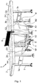
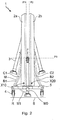
- Table 1 selectively adopts a storage configuration visible to the figure 2 , and a game configuration visible to figures 1 and 4 .
- the first and second flat surfaces 2a1 and 2b1 of the plates 2a, 2b extend in separate planes P1, P2 / non confused with each other.
- these flat surfaces 2a1, 2b1 of the table in storage configuration are substantially parallel to each other and are positioned one face to the other.
- the tray is then folded and its main flat surfaces 2a1, 2b1 face each other
- each at least one stabilizing foot 3 is spaced from the ground S and a plurality of said tread 4, in this case all the tread 4 bears on the ground S.
- These treads 4 support the table 1 on the ground S and allow its rolling on the ground S without opposition from the stabilizing feet 3.
- the first and second planar surfaces 2a1, 2b1 of the tray portions 2a, 2b extend in the same game plane P3 together to form a flat upper surface Sp of the game board.
- This game plane P3 is parallel to the ground plane S.
- each at least one stabilizing foot is supported on the ground S to oppose the movement of the table on the ground while at least some of the treads of said plurality of treads, in the occurrence all running feet, are spread out from the ground plane.
- the table thus goes from a storage configuration where the table is compact and easy to move on the ground to a game configuration where the table is deployed and stabilized on the ground to oppose its movement.
- the connecting mechanism is thus adapted so that, in response to the movement of the table 1 between its play and storage configurations, the movements of the stabilizing feet 3 are synchronized with respect to the movements of the running feet 4.
- the handling of the table is thus facilitated while improving its stability in game configuration.
- the connecting mechanism M is arranged to move each at least one stabilizing foot 3 relative to the plurality of treads 4 in response to an actuation of the connecting mechanism M by a displacement of the first and second portions of plateau 2a, 2b relative to each other.
- the link mechanism M which is linked to the first and second plateau portions 2a, 2b is mechanically actuated by the displacement of said first plateau portion 2a relative to the second plateau portion 2b. Under the effect of this actuation, the linking mechanism M forces the displacement of the plurality of stabilizing feet 3 relative to the plurality of treads 4.
- the user can thus control the passage of the table from its storage configuration to its game configuration and conversely from its game configuration to its storage configuration, forcing a relative movement between the first and second tray portions 2a, 2b .
- the user raises or lowers the first portion of the plate 2a to move it vis-à-vis the second portion 2b.
- the link mechanism M can also be actuated by moving the second plateau portion to induce relative movement between the first and second plateau portions 2a, 2b.
- the mechanism M causes the movement of the different feet of stabilization and rolling relative to each other.
- the first and second tray portions are moved / deployed until they together form an upper flat face Sp of the board game. .
- the binding mechanism M forces the movement of the plurality of stabilizing feet 3 relative to the plurality of treads 4 until all the feet of stabilization are in contact with the ground plane S and all the running feet 4 are all spaced / removed from this ground plane S.
- the table 2 is then in game configuration as on the figures 1 and 4 .
- the stabilizing feet 3 are adjusted so that when the table is in play configuration, the upper flat face Sp is then parallel to the flat ground S which carries the table. Conversely, throughout the passage of the table from its game configuration to its storage configuration, the first and second tray portions are progressively moved / folded towards each other to have their main face 2a1, 2b1 vis-à-vis one another in a substantially vertical position. During this transition from the game configuration to the storage configuration, the link mechanism M forces the plurality of stabilizing feet 3 to move relative to the plurality of treads 4 until all the running feet 4 are in contact with the flat ground S and all the stabilizing feet 3 are all spaced / removed from the ground plane S. The table 1 is then in storage configuration, as on the figure 2 , and it can be simply moved by rolling on the plane S.
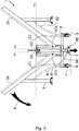
- the arrow F illustrates the lowering force exerted by the user on the first plateau portion 2a to move it to a coplanar position with the second plateau portion 2b.
- the link mechanism M forces the stabilizing feet 3 to move relative to the running feet 4. Once the stabilizing feet 3 are all in contact on the flat ground S, the lowering movement of the first plateau portion 2a becomes impossible and the table is thus maintained in stable play configuration.
- the stabilizing feet comprise pads of flexible material such as rubber to preserve the soil and reduce slippage on the ground. At least some of these pads can be adjustable, for example via a threaded connection, to adjust the length of each stabilization foot concerned.
- the table can thus be stabilized even on a floor with flatness defects.
- each of the wheels R of the four running feet 4 has a pivot orientation of its own and extending in a direction perpendicular to said running plane Pr.
- the link mechanism M comprises a rigid support structure 5 on which are mounted at least four of the tread 4. These four treads together form said plurality of treads.
- This supporting structure 5 here comprises a horizontal base H (when observed in top view).
- Each of the four extremities of the door bears one of the four feet with a wheel.
- the supporting structure 5 also has a rising portion extending perpendicular to a plane in which extends the base H.
- the wheels of these four running feet 4 together define a rolling plane Pr of the wheels of these four feet.
- the first tray portion 2a is pivotally mounted relative to this carrier structure 5 via at least a first hinge axis X10.
- the second plateau portion 2b is also pivotally mounted relative to this supporting structure 5 via at least a second axis of articulation X20 which is parallel to said first axis of articulation X10.
- the actuating piece M0 forms a lever arm mounted to move relative to the carrier structure 5 along an axis X30.
- the two legs of the third pair of stabilizing feet 3c are mechanically linked together to be moved together between their extended and retracted positions.
- the table comprises at least one first spreader bar B1, in this case two bars B1, each articulated on the one hand to the supporting structure 5 and on the other hand to said first pair 3a stabilizing feet 3.
- These bars B1 are placed symmetrically on either side of a longitudinal section plane of the table which is perpendicular to the running surface Pr.
- Each first spacer bar makes it possible to prohibit the displacement of said first pair 3a stabilizing feet relative to the carrier structure 5 as the first tray portion 2a is immobile relative to the carrier structure 5.
- This first bar of gauge B1 also allows to fold down the feet to limit the size in storage configuration.
- the mechanical connection of the actuating member M0 to the first spacer bar B1 comprises a connecting rod M1 which is pivotally connected on one side with the actuating member M0 and on the other hand in pivot connection with the first spacer bar B1.
- These pivot links are along axes of pivots parallel to the axes X10 and X20.
- the position and the displacement of the first actuating part M0 between its first and second positions, and vice versa is a function of the position adopted by the first spacer bar B1 to which is mechanically connected the piece M0.
- each actuating piece M0 is coupled to only one of the legs of the pair 3c and that the displacement of each actuating piece is induced, via the connecting mechanism M, by the displacement only one of the tray portions corresponding to the carrier structure.
- the game table 1 comprises at least a second spacer bar B2, in this case two bars B2, each articulated on the one hand to the supporting structure 5 and on the other hand to said second pair of feet 3b 3.
- These bars B2 are placed symmetrically on either side of the longitudinal section plane which is perpendicular to the running surface of the table.
- Each second spacer bar B2 makes it possible to prohibit the movement of said second pair of stabilizing feet with respect to the supporting structure as long as the second plateau portion is stationary relative to this supporting structure.
- Each second spacer bar B2 also folds the legs of the pair 3b to limit clutter storage configuration.
- each first spreader bar B1 makes it possible to stabilize the position of the first pair 3a stabilizing feet 3 vis-à-vis the carrier structure 5 as the first tray portion 2a remains stationary relative to the structure 5.
- each second spacer bar B2 stabilizes the position of the second pair 3b stabilizing feet 3 vis-à-vis the carrier structure 5 as the second plateau portion 2b remains stationary relative to to the supporting structure 5.
- a second actuating part can be mechanically connected to only one of the feet of the third pair of feet to move it between its extended and retracted positions during the displacement of this second actuating part with respect to the supporting structure 5.
- this second actuating part can be connected to one of the second spacing bars B2 so that the displacement of the second plateau portion with respect to the carrier structure 5 causes the displacement of the second actuating part and the displacement of this foot of the third pair of stabilizing feet 3c.
- the table further comprises a pair of first articulation bars C1 each having a lower end hinged to the supporting structure 5 in a hinge direction common to this pair of first articulation bars C1.
- Each of these bars C1 has an upper end to which is assembled the first tray portion 2a.
- This pair of first articulation bars C1 connects the carrier structure 5 to the first tray portion 2a.
- the lower ends of the articulating bars C1 are each articulated on the bearing structure via pivots X2 axes preferably carried by the horizontal base H of the supporting structure 5.
- the upper ends of the articulation bars C1 are assembled at the first tray portion 2a by axes pivots parallel to said axes X2.
- the actuating part M0 it is also possible for the actuating part M0 to be articulated to one of the bars of these first articulation bars C1, instead of being articulated to the first spreading bar B1. .
- the displacement of the actuating piece M0 between its first and second positions is a function of the position, relative to the bearing structure 5, of the first articulation bar C1 to which this actuating part M0 is articulated.
- the table includes a pair of second hinge bars C2. Each of these bars C2 has a lower end hinged to the supporting structure 5 in a hinge direction X3 common to this pair of second hinge bars C2. Each upper end of bar C2 is assembled the second tray portion 2b.
- This pair of second articulation bars C2 connects the carrier structure to the second tray portion 2b so that the second tray portion is at least partially supported by the carrier structure 5 via this pair of second hinge bars C2.
- connection mechanism M all the joints of the connection mechanism M, are oriented in pivot directions / pivot axes parallel to each other.
- the first axis of articulation X10 allowing the first portion of plate 2a to pivot relative to the supporting structure 5 is assembled to the supporting structure 5 via a first substantially vertical slide G1 visible at the figure 4 .
- This slide G1 allows the first axis of articulation X10 to move along the slide G1 during the passage of the table between its game configurations and storage.
- the second axis of articulation X20 allowing the second portion of plate 2b to pivot relative to the supporting structure 5 is assembled to this supporting structure via a second substantially vertical slide G2 visible at the figure 4 .
- substantially vertical means an orientation of plus or minus 20 ° with respect to a vertical plane.
- This second slide G2 allows the second axis of articulation X20 to move along the slide G2 during the passage of the table between its game configurations and storage.
- first and second hinge axes X10, X20 are parallel to each other.
- each axis X10, X20 is formed along a lateral edge of a plateau portion 2a, 2b which corresponds to it, the presence of these slides G1, G2 makes it possible to lower the height of the pivot axes X10, X20 of the table in storage configuration. This limits its vertical dimensions.
- the table comprises a thread 6 arranged to extend along a plane of thread perpendicular to said upper plane face Sp of play of the table top in play configuration. This net plane passes through a boundary extending between the first and second tray portions 2a, 2b. This table is suitable for playing ping pong.
- Different actuating mechanisms can be used to mechanically connect the actuating member (s) M0 to at least one of the feet of said third pair 3c of stabilizing feet corresponding thereto.
- an actuating mechanism may be a pinion / rack mechanism, the pinion being mounted at the end of the actuating part to cause the movement of the rack itself connected to the third pair of stabilizing feet.
- this actuating mechanism may be a cam and cam follower mechanism, the cam being mounted at the end of the actuating part to cause the displacement of the cam follower himself connected to the third pair of stabilizing feet.
- this actuating mechanism may be a helical link mechanism comprising a screw and a nut, the screw being rotated by the rotation of the end of the control part to cause the displacement of the nut. which is itself connected to the third pair of stabilizing feet to move it in translation.
- connection between the actuating part and the third pair of stabilizing feet are conceivable as long as they make it possible to control the displacement of the third pair of feet relative to the bearing structure as a function of the pivoting of the first plateau portion with respect to this same carrier structure.
- the connecting mechanism M may comprise a mechanical actuation control mechanically actuable by the force of a user of the table to move the at least one stabilization foot 3 relative to the plurality of running feet 4 and thus move said at least some of the feet of said plurality of treads relative to the ground.
- This mechanical actuation command is, for example, a foot pedal actuated by the user or a joystick manually operable by the user.
- each of these controls being connected to at least one of the corresponding stabilizing feet to move it relative to the plurality of treads 4 and thus spreading at least some of the treads of said plurality of treads relative to the ground.
- a mechanical actuation command such as a pedal
- Each mechanical actuation command may also be provided to control the movement of said at least one of the corresponding stabilizing feet relative to the plurality of treads 4 while the first and second tray portions 2a, 2b remain motionless relative to each other.
- the displacement of stabilizing feet can be decorrelated from the displacement of the tray portions relative to each other.
- a mechanical actuation control may have a control offset accessible on either side of the table to allow the user to move the at least one stabilization foot from one or the other. other flanks of the table.
Landscapes
- Motorcycle And Bicycle Frame (AREA)
- Accommodation For Nursing Or Treatment Tables (AREA)
Applications Claiming Priority (1)
| Application Number | Priority Date | Filing Date | Title |
|---|---|---|---|
| FR1660853A FR3058324B1 (fr) | 2016-11-09 | 2016-11-09 | Table de jeu pourvue de roulettes et de pieds retractables |
Publications (2)
| Publication Number | Publication Date |
|---|---|
| EP3320802A1 true EP3320802A1 (de) | 2018-05-16 |
| EP3320802B1 EP3320802B1 (de) | 2020-09-23 |
Family
ID=58009968
Family Applications (1)
| Application Number | Title | Priority Date | Filing Date |
|---|---|---|---|
| EP17200928.4A Active EP3320802B1 (de) | 2016-11-09 | 2017-11-09 | Spieltisch, der mit rollen und einziehbaren beinen ausgestattet ist |
Country Status (2)
| Country | Link |
|---|---|
| EP (1) | EP3320802B1 (de) |
| FR (1) | FR3058324B1 (de) |
Cited By (2)
| Publication number | Priority date | Publication date | Assignee | Title |
|---|---|---|---|---|
| DE102019101726B4 (de) * | 2019-01-24 | 2020-11-12 | Sponeta Gmbh | Verbindungselement für Tischtennistisch |
| EP3903637A1 (de) | 2020-04-29 | 2021-11-03 | Cornilleau SAS | Spieltisch, der mindestens ein stabilisierendes tischbein umfasst |
Citations (4)
| Publication number | Priority date | Publication date | Assignee | Title |
|---|---|---|---|---|
| US3245363A (en) * | 1964-04-06 | 1966-04-12 | Hamilton Mfg Co | Folding table assembly with stabilizing means |
| DE1684914A1 (de) * | 1965-11-22 | 1971-08-19 | Sico Inc | Klappbares Gestell |
| FR2368917A2 (fr) * | 1976-10-27 | 1978-05-26 | Lafa Tables Sieges | Nouvelle table |
| DE2835395A1 (de) * | 1978-08-12 | 1980-02-21 | Eduard Haider | Vorrichtung zum schwenken der plattenhaelften von tischtennis-platten |
-
2016
- 2016-11-09 FR FR1660853A patent/FR3058324B1/fr active Active
-
2017
- 2017-11-09 EP EP17200928.4A patent/EP3320802B1/de active Active
Patent Citations (4)
| Publication number | Priority date | Publication date | Assignee | Title |
|---|---|---|---|---|
| US3245363A (en) * | 1964-04-06 | 1966-04-12 | Hamilton Mfg Co | Folding table assembly with stabilizing means |
| DE1684914A1 (de) * | 1965-11-22 | 1971-08-19 | Sico Inc | Klappbares Gestell |
| FR2368917A2 (fr) * | 1976-10-27 | 1978-05-26 | Lafa Tables Sieges | Nouvelle table |
| DE2835395A1 (de) * | 1978-08-12 | 1980-02-21 | Eduard Haider | Vorrichtung zum schwenken der plattenhaelften von tischtennis-platten |
Cited By (3)
| Publication number | Priority date | Publication date | Assignee | Title |
|---|---|---|---|---|
| DE102019101726B4 (de) * | 2019-01-24 | 2020-11-12 | Sponeta Gmbh | Verbindungselement für Tischtennistisch |
| EP3903637A1 (de) | 2020-04-29 | 2021-11-03 | Cornilleau SAS | Spieltisch, der mindestens ein stabilisierendes tischbein umfasst |
| FR3109713A1 (fr) | 2020-04-29 | 2021-11-05 | Cornilleau Sas | Table de jeu comprenant au moins un pied de stabilisation |
Also Published As
| Publication number | Publication date |
|---|---|
| FR3058324B1 (fr) | 2020-10-16 |
| EP3320802B1 (de) | 2020-09-23 |
| FR3058324A1 (fr) | 2018-05-11 |
Similar Documents
| Publication | Publication Date | Title |
|---|---|---|
| EP0179712B1 (de) | Fahrbare Tragbahre mit einer höhenverstellbaren Liegefläche | |
| FR2483201A1 (fr) | Chaise au dossier inclinable comportant ou non un appui pour jambes mobile | |
| CA3002784C (fr) | Systeme et methode de manutention pour faciliter la maintenance d'une unite de couchage, en particulier un lit medicalise | |
| EP3320802B1 (de) | Spieltisch, der mit rollen und einziehbaren beinen ausgestattet ist | |
| FR2951372A1 (fr) | Lit d'hopital ou d'hebergement a plan de couchage reglable | |
| FR2862002A1 (fr) | Table convertible en billard | |
| WO1999056999A1 (fr) | Ensemble bidirectionnel de guidage le long d'un rail autorisant un deport lateral pour un essieu routier | |
| CA1142210A (fr) | Table a rallonge centrale | |
| CA2903954C (fr) | Atterrisseur d'aeronef muni d'une olive reglable | |
| WO2016075412A1 (fr) | Mobilier comprenant un corps supporte par des pieds | |
| EP3169415A1 (de) | Klappbilliardtisch | |
| JP4059769B2 (ja) | リンク機構 | |
| EP0712287B1 (de) | Verbesserte auslageeinheit und einheitanordnung in einem raum, der mit einer öffnung versehen ist | |
| EP1637655B1 (de) | Bodensäge | |
| CH705989B1 (fr) | Dispositif de guidage et de levage de garde-corps de plateforme de travail en encorbellement. | |
| FR3041312A1 (fr) | Poignee pliante de poussette pour enfant | |
| FR2578207A2 (fr) | Perfectionnements aux sieges de vehicule a dossier reglable en inclinaison | |
| WO2003092438A2 (fr) | Tabourets extensibles | |
| FR3076049A1 (fr) | Simulateur de pilotage a faible encombrement hors utilisation | |
| FR2826845A1 (fr) | Sommier a lattes a fermete variable | |
| WO2023242432A1 (fr) | Table pliable a pieds telescopiques | |
| FR3136640A1 (fr) | Table pliable à pieds télescopiques | |
| FR2872029A1 (fr) | Vehicule automobile pour personne a mobilite reduite | |
| FR2883715A1 (fr) | Canape-lit a pliage transversal integrant un mecanisme de deploiement/repliement comprenant un element coude dont une branche est couplee a une partie pied du sommier | |
| CH274782A (fr) | Table transformable. |
Legal Events
| Date | Code | Title | Description |
|---|---|---|---|
| PUAI | Public reference made under article 153(3) epc to a published international application that has entered the european phase |
Free format text: ORIGINAL CODE: 0009012 |
|
| STAA | Information on the status of an ep patent application or granted ep patent |
Free format text: STATUS: THE APPLICATION HAS BEEN PUBLISHED |
|
| AK | Designated contracting states |
Kind code of ref document: A1 Designated state(s): AL AT BE BG CH CY CZ DE DK EE ES FI FR GB GR HR HU IE IS IT LI LT LU LV MC MK MT NL NO PL PT RO RS SE SI SK SM TR |
|
| AX | Request for extension of the european patent |
Extension state: BA ME |
|
| STAA | Information on the status of an ep patent application or granted ep patent |
Free format text: STATUS: REQUEST FOR EXAMINATION WAS MADE |
|
| 17P | Request for examination filed |
Effective date: 20181102 |
|
| RBV | Designated contracting states (corrected) |
Designated state(s): AL AT BE BG CH CY CZ DE DK EE ES FI FR GB GR HR HU IE IS IT LI LT LU LV MC MK MT NL NO PL PT RO RS SE SI SK SM TR |
|
| STAA | Information on the status of an ep patent application or granted ep patent |
Free format text: STATUS: EXAMINATION IS IN PROGRESS |
|
| 17Q | First examination report despatched |
Effective date: 20190102 |
|
| GRAP | Despatch of communication of intention to grant a patent |
Free format text: ORIGINAL CODE: EPIDOSNIGR1 |
|
| STAA | Information on the status of an ep patent application or granted ep patent |
Free format text: STATUS: GRANT OF PATENT IS INTENDED |
|
| RIC1 | Information provided on ipc code assigned before grant |
Ipc: A47B 3/087 20060101ALN20200318BHEP Ipc: A47B 25/00 20060101AFI20200318BHEP |
|
| INTG | Intention to grant announced |
Effective date: 20200414 |
|
| GRAS | Grant fee paid |
Free format text: ORIGINAL CODE: EPIDOSNIGR3 |
|
| GRAA | (expected) grant |
Free format text: ORIGINAL CODE: 0009210 |
|
| STAA | Information on the status of an ep patent application or granted ep patent |
Free format text: STATUS: THE PATENT HAS BEEN GRANTED |
|
| AK | Designated contracting states |
Kind code of ref document: B1 Designated state(s): AL AT BE BG CH CY CZ DE DK EE ES FI FR GB GR HR HU IE IS IT LI LT LU LV MC MK MT NL NO PL PT RO RS SE SI SK SM TR |
|
| REG | Reference to a national code |
Ref country code: GB Ref legal event code: FG4D Free format text: NOT ENGLISH |
|
| REG | Reference to a national code |
Ref country code: CH Ref legal event code: EP |
|
| REG | Reference to a national code |
Ref country code: IE Ref legal event code: FG4D Free format text: LANGUAGE OF EP DOCUMENT: FRENCH |
|
| REG | Reference to a national code |
Ref country code: DE Ref legal event code: R096 Ref document number: 602017024048 Country of ref document: DE Ref country code: AT Ref legal event code: REF Ref document number: 1315490 Country of ref document: AT Kind code of ref document: T Effective date: 20201015 |
|
| PG25 | Lapsed in a contracting state [announced via postgrant information from national office to epo] |
Ref country code: FI Free format text: LAPSE BECAUSE OF FAILURE TO SUBMIT A TRANSLATION OF THE DESCRIPTION OR TO PAY THE FEE WITHIN THE PRESCRIBED TIME-LIMIT Effective date: 20200923 Ref country code: SE Free format text: LAPSE BECAUSE OF FAILURE TO SUBMIT A TRANSLATION OF THE DESCRIPTION OR TO PAY THE FEE WITHIN THE PRESCRIBED TIME-LIMIT Effective date: 20200923 Ref country code: HR Free format text: LAPSE BECAUSE OF FAILURE TO SUBMIT A TRANSLATION OF THE DESCRIPTION OR TO PAY THE FEE WITHIN THE PRESCRIBED TIME-LIMIT Effective date: 20200923 Ref country code: GR Free format text: LAPSE BECAUSE OF FAILURE TO SUBMIT A TRANSLATION OF THE DESCRIPTION OR TO PAY THE FEE WITHIN THE PRESCRIBED TIME-LIMIT Effective date: 20201224 Ref country code: NO Free format text: LAPSE BECAUSE OF FAILURE TO SUBMIT A TRANSLATION OF THE DESCRIPTION OR TO PAY THE FEE WITHIN THE PRESCRIBED TIME-LIMIT Effective date: 20201223 Ref country code: BG Free format text: LAPSE BECAUSE OF FAILURE TO SUBMIT A TRANSLATION OF THE DESCRIPTION OR TO PAY THE FEE WITHIN THE PRESCRIBED TIME-LIMIT Effective date: 20201223 |
|
| REG | Reference to a national code |
Ref country code: AT Ref legal event code: MK05 Ref document number: 1315490 Country of ref document: AT Kind code of ref document: T Effective date: 20200923 |
|
| PG25 | Lapsed in a contracting state [announced via postgrant information from national office to epo] |
Ref country code: LV Free format text: LAPSE BECAUSE OF FAILURE TO SUBMIT A TRANSLATION OF THE DESCRIPTION OR TO PAY THE FEE WITHIN THE PRESCRIBED TIME-LIMIT Effective date: 20200923 Ref country code: RS Free format text: LAPSE BECAUSE OF FAILURE TO SUBMIT A TRANSLATION OF THE DESCRIPTION OR TO PAY THE FEE WITHIN THE PRESCRIBED TIME-LIMIT Effective date: 20200923 |
|
| REG | Reference to a national code |
Ref country code: NL Ref legal event code: MP Effective date: 20200923 |
|
| REG | Reference to a national code |
Ref country code: LT Ref legal event code: MG4D |
|
| PG25 | Lapsed in a contracting state [announced via postgrant information from national office to epo] |
Ref country code: EE Free format text: LAPSE BECAUSE OF FAILURE TO SUBMIT A TRANSLATION OF THE DESCRIPTION OR TO PAY THE FEE WITHIN THE PRESCRIBED TIME-LIMIT Effective date: 20200923 Ref country code: SM Free format text: LAPSE BECAUSE OF FAILURE TO SUBMIT A TRANSLATION OF THE DESCRIPTION OR TO PAY THE FEE WITHIN THE PRESCRIBED TIME-LIMIT Effective date: 20200923 Ref country code: RO Free format text: LAPSE BECAUSE OF FAILURE TO SUBMIT A TRANSLATION OF THE DESCRIPTION OR TO PAY THE FEE WITHIN THE PRESCRIBED TIME-LIMIT Effective date: 20200923 Ref country code: PT Free format text: LAPSE BECAUSE OF FAILURE TO SUBMIT A TRANSLATION OF THE DESCRIPTION OR TO PAY THE FEE WITHIN THE PRESCRIBED TIME-LIMIT Effective date: 20210125 Ref country code: CZ Free format text: LAPSE BECAUSE OF FAILURE TO SUBMIT A TRANSLATION OF THE DESCRIPTION OR TO PAY THE FEE WITHIN THE PRESCRIBED TIME-LIMIT Effective date: 20200923 Ref country code: LT Free format text: LAPSE BECAUSE OF FAILURE TO SUBMIT A TRANSLATION OF THE DESCRIPTION OR TO PAY THE FEE WITHIN THE PRESCRIBED TIME-LIMIT Effective date: 20200923 |
|
| PG25 | Lapsed in a contracting state [announced via postgrant information from national office to epo] |
Ref country code: IS Free format text: LAPSE BECAUSE OF FAILURE TO SUBMIT A TRANSLATION OF THE DESCRIPTION OR TO PAY THE FEE WITHIN THE PRESCRIBED TIME-LIMIT Effective date: 20210123 Ref country code: PL Free format text: LAPSE BECAUSE OF FAILURE TO SUBMIT A TRANSLATION OF THE DESCRIPTION OR TO PAY THE FEE WITHIN THE PRESCRIBED TIME-LIMIT Effective date: 20200923 Ref country code: AT Free format text: LAPSE BECAUSE OF FAILURE TO SUBMIT A TRANSLATION OF THE DESCRIPTION OR TO PAY THE FEE WITHIN THE PRESCRIBED TIME-LIMIT Effective date: 20200923 Ref country code: AL Free format text: LAPSE BECAUSE OF FAILURE TO SUBMIT A TRANSLATION OF THE DESCRIPTION OR TO PAY THE FEE WITHIN THE PRESCRIBED TIME-LIMIT Effective date: 20200923 Ref country code: ES Free format text: LAPSE BECAUSE OF FAILURE TO SUBMIT A TRANSLATION OF THE DESCRIPTION OR TO PAY THE FEE WITHIN THE PRESCRIBED TIME-LIMIT Effective date: 20200923 |
|
| REG | Reference to a national code |
Ref country code: DE Ref legal event code: R097 Ref document number: 602017024048 Country of ref document: DE |
|
| PG25 | Lapsed in a contracting state [announced via postgrant information from national office to epo] |
Ref country code: MC Free format text: LAPSE BECAUSE OF FAILURE TO SUBMIT A TRANSLATION OF THE DESCRIPTION OR TO PAY THE FEE WITHIN THE PRESCRIBED TIME-LIMIT Effective date: 20200923 Ref country code: SK Free format text: LAPSE BECAUSE OF FAILURE TO SUBMIT A TRANSLATION OF THE DESCRIPTION OR TO PAY THE FEE WITHIN THE PRESCRIBED TIME-LIMIT Effective date: 20200923 |
|
| REG | Reference to a national code |
Ref country code: CH Ref legal event code: PL |
|
| PG25 | Lapsed in a contracting state [announced via postgrant information from national office to epo] |
Ref country code: LU Free format text: LAPSE BECAUSE OF NON-PAYMENT OF DUE FEES Effective date: 20201109 |
|
| PLBE | No opposition filed within time limit |
Free format text: ORIGINAL CODE: 0009261 |
|
| STAA | Information on the status of an ep patent application or granted ep patent |
Free format text: STATUS: NO OPPOSITION FILED WITHIN TIME LIMIT |
|
| REG | Reference to a national code |
Ref country code: BE Ref legal event code: MM Effective date: 20201130 |
|
| PG25 | Lapsed in a contracting state [announced via postgrant information from national office to epo] |
Ref country code: CH Free format text: LAPSE BECAUSE OF NON-PAYMENT OF DUE FEES Effective date: 20201130 Ref country code: SI Free format text: LAPSE BECAUSE OF FAILURE TO SUBMIT A TRANSLATION OF THE DESCRIPTION OR TO PAY THE FEE WITHIN THE PRESCRIBED TIME-LIMIT Effective date: 20200923 Ref country code: LI Free format text: LAPSE BECAUSE OF NON-PAYMENT OF DUE FEES Effective date: 20201130 Ref country code: DK Free format text: LAPSE BECAUSE OF FAILURE TO SUBMIT A TRANSLATION OF THE DESCRIPTION OR TO PAY THE FEE WITHIN THE PRESCRIBED TIME-LIMIT Effective date: 20200923 |
|
| 26N | No opposition filed |
Effective date: 20210624 |
|
| PG25 | Lapsed in a contracting state [announced via postgrant information from national office to epo] |
Ref country code: IT Free format text: LAPSE BECAUSE OF FAILURE TO SUBMIT A TRANSLATION OF THE DESCRIPTION OR TO PAY THE FEE WITHIN THE PRESCRIBED TIME-LIMIT Effective date: 20200923 Ref country code: IE Free format text: LAPSE BECAUSE OF NON-PAYMENT OF DUE FEES Effective date: 20201109 |
|
| PG25 | Lapsed in a contracting state [announced via postgrant information from national office to epo] |
Ref country code: TR Free format text: LAPSE BECAUSE OF FAILURE TO SUBMIT A TRANSLATION OF THE DESCRIPTION OR TO PAY THE FEE WITHIN THE PRESCRIBED TIME-LIMIT Effective date: 20200923 Ref country code: MT Free format text: LAPSE BECAUSE OF FAILURE TO SUBMIT A TRANSLATION OF THE DESCRIPTION OR TO PAY THE FEE WITHIN THE PRESCRIBED TIME-LIMIT Effective date: 20200923 Ref country code: CY Free format text: LAPSE BECAUSE OF FAILURE TO SUBMIT A TRANSLATION OF THE DESCRIPTION OR TO PAY THE FEE WITHIN THE PRESCRIBED TIME-LIMIT Effective date: 20200923 |
|
| PG25 | Lapsed in a contracting state [announced via postgrant information from national office to epo] |
Ref country code: MK Free format text: LAPSE BECAUSE OF FAILURE TO SUBMIT A TRANSLATION OF THE DESCRIPTION OR TO PAY THE FEE WITHIN THE PRESCRIBED TIME-LIMIT Effective date: 20200923 |
|
| PG25 | Lapsed in a contracting state [announced via postgrant information from national office to epo] |
Ref country code: BE Free format text: LAPSE BECAUSE OF NON-PAYMENT OF DUE FEES Effective date: 20201130 |
|
| PG25 | Lapsed in a contracting state [announced via postgrant information from national office to epo] |
Ref country code: NL Free format text: LAPSE BECAUSE OF NON-PAYMENT OF DUE FEES Effective date: 20200923 |
|
| PGFP | Annual fee paid to national office [announced via postgrant information from national office to epo] |
Ref country code: DE Payment date: 20251119 Year of fee payment: 9 |
|
| PGFP | Annual fee paid to national office [announced via postgrant information from national office to epo] |
Ref country code: GB Payment date: 20251121 Year of fee payment: 9 |
|
| PGFP | Annual fee paid to national office [announced via postgrant information from national office to epo] |
Ref country code: FR Payment date: 20251126 Year of fee payment: 9 |