EP3320802B1 - Spieltisch, der mit rollen und einziehbaren beinen ausgestattet ist - Google Patents
Spieltisch, der mit rollen und einziehbaren beinen ausgestattet ist Download PDFInfo
- Publication number
- EP3320802B1 EP3320802B1 EP17200928.4A EP17200928A EP3320802B1 EP 3320802 B1 EP3320802 B1 EP 3320802B1 EP 17200928 A EP17200928 A EP 17200928A EP 3320802 B1 EP3320802 B1 EP 3320802B1
- Authority
- EP
- European Patent Office
- Prior art keywords
- feet
- pair
- supporting structure
- stabilizing
- ground
- Prior art date
- Legal status (The legal status is an assumption and is not a legal conclusion. Google has not performed a legal analysis and makes no representation as to the accuracy of the status listed.)
- Active
Links
Images
Classifications
-
- A—HUMAN NECESSITIES
- A47—FURNITURE; DOMESTIC ARTICLES OR APPLIANCES; COFFEE MILLS; SPICE MILLS; SUCTION CLEANERS IN GENERAL
- A47B—TABLES; DESKS; OFFICE FURNITURE; CABINETS; DRAWERS; GENERAL DETAILS OF FURNITURE
- A47B25/00—Card tables; Tables for other games
- A47B25/003—Card tables; Tables for other games for table tennis
- A47B2025/006—Card tables; Tables for other games for table tennis with retractable wheels
-
- A—HUMAN NECESSITIES
- A47—FURNITURE; DOMESTIC ARTICLES OR APPLIANCES; COFFEE MILLS; SPICE MILLS; SUCTION CLEANERS IN GENERAL
- A47B—TABLES; DESKS; OFFICE FURNITURE; CABINETS; DRAWERS; GENERAL DETAILS OF FURNITURE
- A47B3/00—Folding or stowable tables
- A47B3/08—Folding or stowable tables with legs pivoted to top or underframe
- A47B3/083—Folding or stowable tables with legs pivoted to top or underframe with foldable top leaves
- A47B3/087—Folding or stowable tables with legs pivoted to top or underframe with foldable top leaves with struts supporting the legs
Definitions
- the present invention relates to the field of gaming tables.
- game tables such as ping pong, which are foldable to facilitate storage / movement.
- the table according to the invention is essentially characterized in that the table is arranged so that in its playing configuration, at least some of the running feet of said plurality of running feet are spaced from the flat ground.
- All of the stabilization feet are arranged to oppose together the movement of the table on the ground.
- each stabilization foot may have a friction end which opposes the sliding of the foot on the ground when this end is resting on the ground.
- the table has several stabilizing feet each with a castor to allow rolling on the ground, however, these casters of these stabilizing feet are respectively oriented so that when they are all in position. contact with the ground, they then oppose together the rolling of the table because these rollers of the stabilizing feet do not have a common rolling direction.
- the table according to the invention when the table according to the invention is in its play configuration, at least some of the running feet of said plurality of running feet are spaced from the flat ground while each at least one stabilizing foot is in contact with the ground. to oppose the movement of the table on the floor.
- Removing at least some of the running feet from the ground allows at least part of the weight of the table to be transferred to the stabilization feet, which increases the ability of these stabilizing feet to oppose moving the table on the level floor.
- the table according to the invention when placed in its playing configuration, thus exhibits improved stability.
- the table is arranged so that when it is in the play configuration, each stabilization foot is supported on the flat ground. to support the table while all the feet of bearing are removed / not supported from the level ground.
- the connecting mechanism is designed to simultaneously move each at least one stabilization foot relative to the plurality of running feet.
- the control of variation of the relative positioning of the running feet with respect to each at least one stabilizing foot is thus centralized and carried out simultaneously, which facilitates the actuation of the table by the user.
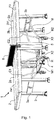
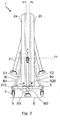
- the table 1 selectively adopts a storage configuration visible from the figure 2 , and a game configuration visible to figures 1 and 4 .
- the first and second flat surfaces 2a1 and 2b1 of the plates 2a, 2b extend in separate planes P1, P2 / not coincident with each other.
- these flat surfaces 2a1, 2b1 of the table in the storage configuration are substantially parallel to each other and are positioned facing each other.
- the plate is then folded and its main flat surfaces 2a1, 2b1 face each other.
- each stabilizing foot 3 is moved away from the ground S and a plurality of said rolling feet 4, in this case all the rolling feet 4, rests on the ground S.
- These rolling feet 4 support the table 1 on the floor S and allow it to roll on the floor S without opposition from the stabilization feet 3.
- the first and second flat surfaces 2a1, 2b1 of the board portions 2a, 2b extend in the same game plane P3 to together form an upper planar game face Sp of the board.
- This game plane P3 is parallel to the ground plane S.
- each stabilization foot rests on the ground S to oppose the movement of the table on the ground while at least some of the rolling feet of said plurality of rolling feet, in this case all the running feet are spaced from the level ground.
- the table thus goes from a storage configuration where the table is compact and easy to move on the floor to a play configuration where the table is deployed and stabilized on the floor to oppose its movement.
- the connecting mechanism is thus adapted so that, in response to the movement of the table 1 between its play and storage configurations, the movements of the stabilizing feet 3 are synchronized with the movements of the running feet 4.
- the handling of the table is thus facilitated while improving its stability in game configuration.
- the link mechanism M is arranged to move each at least one stabilization feet 3 relative to the plurality of running feet 4 in response to an actuation of the link mechanism M by a displacement of the first and second portions of plate 2a, 2b relative to each other.
- the link mechanism M which is linked to the first and second plate portions 2a, 2b is actuated mechanically by the displacement of said first plate portion 2a relative to the second plate portion 2b. Under the effect of this actuation, the link mechanism M forces the plurality of stabilization feet 3 to move relative to the plurality of running feet 4.
- the user can thus control the passage of the table from its storage configuration to its game configuration and vice versa from its game configuration to its storage configuration, by forcing a relative movement between the first and second tray portions 2a, 2b .
- the user raises or lowers the first portion of the plate 2a to move it vis-à-vis the second portion 2b.
- the M link mechanism can also be actuated by displacement of the second plate portion to induce a relative displacement between the first and second plate portions 2a, 2b.
- the mechanism M drives the movement of the various stabilization and rolling feet relative to one another.
- the first and second board portions are moved / deployed until they together form an upper planar game face Sp of the board .
- the linkage mechanism M forces the displacement of the plurality of stabilizing feet 3 relative to the plurality of running feet 4 until all the feet stabilization devices are in contact with the plane ground S and that all the running feet 4 are all moved away from this plane ground S.
- Table 2 is then in the play configuration as on the figures 1 and 4 .
- the stabilization feet 3 are adjusted so that when the table is in the playing configuration, the upper plane face Sp is then parallel to the plane floor S which carries the table. Conversely, throughout the passage of the table from its playing configuration to its storage configuration, the first and second board portions are gradually moved / folded towards each other until they have their main faces 2a1, 2b1. facing each other in a substantially vertical position. During this transition from the play configuration to the storage configuration, the link mechanism M forces the movement of the plurality of stabilizing feet 3 relative to the plurality of rolling feet 4 until all the rolling feet 4 are in contact with the ground plane S and that all the stabilization feet 3 are all spaced / moved away from this plane ground S. Table 1 is then in storage configuration, as on the figure 2 , and it can be simply moved by rolling on the ground plane S.
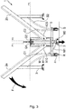
- FIG. 3 Moving the table from its storage configuration to the figure 2 to the game configuration of figures 1 and 4 is illustrated by the figure 3 .
- the arrow F illustrates the lowering force exerted by the user on the first plate portion 2a to move it to a position coplanar with the second plate portion 2b.
- the connecting mechanism M forces the movement of the stabilizing feet 3 relative to the running feet 4. A Once the stabilization feet 3 are all in contact with the plane ground S, the lowering movement of the first plate portion 2a becomes impossible and the table is thus maintained in a stable playing configuration.
- the stabilization feet comprise pads made of flexible material such as rubber to preserve the ground and reduce sliding on the ground. At least some of these pads may be adjustable, for example via a threaded assembly, to adjust the length of each stabilization foot concerned.
- the table can thus be stabilized even on a ground having defects of flatness.
- each of the rollers R of the four rolling feet 4 has an orientation pivot which is specific to it and which extends in a direction perpendicular to said rolling surface Pr.
- the connecting mechanism M comprises a rigid supporting structure 5 on which are mounted at least four of the running feet 4. These four of the running feet together form said plurality of running feet.
- This supporting structure 5 here comprises a horizontal H-shaped base (when observed in top view). Each of the four ends of the H has one of the four roller feet.
- the supporting structure 5 also has a rising portion extending perpendicularly relative to a plane in which the H-shaped base extends.
- the rollers of these four rolling feet 4 together defining a rolling plane Pr of the rollers of these four feet.
- the first plate portion 2a is mounted to pivot relative to this supporting structure 5 via at least one first articulation axis X10.
- the second plate portion 2b is also mounted to pivot relative to this supporting structure 5 via at least one second articulation axis X20 which is parallel to said first articulation axis X10.
- the actuating part M0 forms a lever arm mounted to move relative to the supporting structure 5 along an axis X30.
- the two legs of the third pair of stabilizing legs 3c are mechanically linked together to be moved together between their extended and retracted positions.
- the table has at least a first spreader bar B1, in this case two bars B1, each articulated on the one hand to the supporting structure 5 and on the other hand to said first pair 3a of stabilization feet 3.
- These bars B1 are placed symmetrically on either side of a plane of longitudinal section of the table which is perpendicular to the running surface Pr.
- Each first spacer bar makes it possible to prevent the movement of said first pair 3a of stabilizing feet relative to the supporting structure 5 as long as the first portion of the plate 2a is stationary relative to the supporting structure 5.
- This first bar of spacing B1 also allows the feet to be folded down to limit the bulk in the storage configuration.
- the mechanical connection of the actuating part M0 to the first spacer bar B1 comprises a connecting rod M1 which is on one side in a pivot connection with the actuating part M0 and on the other hand in pivot connection with the first spreader bar B1.
- These pivot connections are along pivot axes parallel to the X10 and X20 axes.
- the position and the displacement of the first actuating part M0 between its first and second positions, and vice versa depend on the position adopted by the first spacer bar B1 to which the device is mechanically connected. MO room.
- each actuating part M0 is coupled to only one of the feet of the pair 3c and that the displacement of each actuating part is induced, via the link mechanism M, by the displacement of only one of the plate portions which corresponds to it relative to the supporting structure.
- the game table 1 comprises at least one second spreader bar B2, in this case two bars B2, each articulated on the one hand to the supporting structure 5 and on the other hand to said second pair 3b of feet. stabilization 3. These bars B2 are placed symmetrically on either side of the plane of longitudinal section which is perpendicular to the running plane of the table.
- Each second spacer bar B2 makes it possible to prevent the movement of said second pair of stabilization feet relative to the supporting structure as long as the second portion of the platform is stationary relative to this supporting structure.
- Each second B2 spacer bar also makes it possible to fold down the feet of the pair 3b to limit the bulk in the storage configuration.
- each first spreader bar B1 makes it possible to stabilize the position of the first pair 3a of stabilization feet 3 with respect to the supporting structure 5 as long as the first portion of the plate 2a remains stationary relative to the structure. carrier 5.
- each second spreader bar B2 makes it possible to stabilize the position of the second pair 3b of stabilization feet 3 with respect to the supporting structure 5 as long as the second portion of plate 2b remains stationary relative to the supporting structure. to the supporting structure 5.
- a second actuating part can be mechanically connected to only one of the legs of the third pair of legs in order to move it between its extended and retracted positions during the movement of this second actuating part relative to the supporting structure 5.
- this second actuating part can be connected to one of the second spacer bars B2 so that the movement of the second portion of the plate vis-à-vis the supporting structure 5 causes the displacement of this second actuating part and the displacement of this foot of the third pair of stabilization feet 3c.
- the table further comprises a pair of first articulation bars C1 each having a lower end articulated to the supporting structure 5 in a direction of articulation common to this pair of first articulation bars C1.
- Each of these C1 bars has an upper end to which the first plate portion 2a is assembled.
- This pair of first articulation bars C1 connects the supporting structure 5 to the first plate portion 2a.
- the lower ends of the articulation bars C1 are each articulated on the supporting structure via pivots of axes X2 preferably carried by the horizontal H-shaped base of the supporting structure 5.
- the upper ends of the articulation bars C1 are assembled at the first portion of plate 2a by pivots with axes parallel to said axes X2.
- the actuating part MO it is also possible for the actuating part MO to be articulated to one of the bars of these first articulation bars C1, instead of being articulated to the first spreader bar B1.
- the movement of the actuating part MO between its first and second positions is a function of the position, with respect to the supporting structure 5, of the first articulation bar C1 to which this actuating part M0 is articulated.
- the table includes a pair of second C2 hinge bars. Each of these bars C2 has a lower end articulated to the supporting structure 5 in an articulation direction X3 common to this pair of second articulation bars C2. Each upper end of bar C2 is assembled with the second plate portion 2b. This pair of second C2 articulation bars connects the supporting structure to the second plate portion 2b so that this second plate portion is at least partially supported by the supporting structure 5 via this pair of second articulation bars C2.
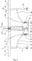
- the first articulation axis X10 allowing the first portion of plate 2a to pivot relative to the supporting structure 5 is assembled to the supporting structure 5 via a first substantially vertical slide G1 visible at the bottom. figure 4 .
- This slide G1 allows the first articulation axis X10 to move along the slide G1 during the passage of the table between its play and storage configurations.
- the second articulation axis X20 allowing the second plate portion 2b to pivot relative to the supporting structure 5 is assembled to this supporting structure via a second substantially vertical slideway G2 visible at the bottom. figure 4 .
- substantially vertical is meant an orientation of plus or minus 20 ° relative to a vertical plane.
- This second slide G2 allows the second articulation axis X20 to move along the slide G2 during the passage of the table between its game and storage configurations.
- first and second articulation axes X10, X20 are mutually parallel.
- X20 is formed along a lateral edge of a plate portion 2a, 2b which corresponds to it, the presence of these slides G1, G2 makes it possible to lower the height of the pivot axes X10, X20 by the table in storage configuration. This limits its vertical size.
- the table comprises a net 6 arranged to extend along a net plane perpendicular to said upper flat playing face Sp of the table top in game configuration. This net plane passes through a limit extending between the first and second tray portions 2a, 2b. This table is suitable for playing ping pong.
- Different actuation mechanisms can be used to mechanically connect the actuating part (s) M0 to at least one of the feet of said third pair 3c of stabilization feet which corresponds to it.
- an actuation mechanism may be a pinion / rack mechanism, the pinion being mounted at the end of the actuating part to cause the displacement of the rack itself connected to the third pair of stabilization feet.
- this actuation mechanism can be a cam and cam follower mechanism, the cam being mounted at the end of the actuating part to cause the movement of the cam follower itself connected to the third pair of stabilizing feet.
- this actuating mechanism can be a helical link mechanism comprising a screw and a nut, the screw being rotated by the rotation of the end of the control part to cause the displacement of the nut. which is itself connected to the third pair of stabilization feet to move it in translation.
- connection between the actuating part and the third pair of stabilizing feet can be envisaged as long as they make it possible to control the displacement of the third pair of feet relative to the supporting structure as a function of the pivoting of the first. tray portion with respect to this same supporting structure.
- the link mechanism M may include a mechanical actuation control that can be actuated mechanically by the force of a user of the table to move said at least one stabilization foot 3 relative to the plurality of rolling feet 4 and thus moving said at least some of the rolling feet of said plurality of running feet away from the ground.
- This mechanical actuation control is, for example, a pedal actuable by the foot by the user or a joystick actuable manually by the user.
- a mechanical actuation control such as a pedal, on each side of the table.
- Each mechanical actuation control can also be provided to control the movement of said at least one of the stabilizing feet which corresponds to it with respect to the plurality of running feet 4 while the first and second plate portions 2a, 2b remain motionless in relation to each other.
- the movement of the stabilization feet can be decorrelated from the movement of the plate portions relative to each other.
- a mechanical actuation control may have a control offset accessible from either side of the table to allow the user to move said at least one stabilization foot from one or the other. other side of the table.
Landscapes
- Motorcycle And Bicycle Frame (AREA)
- Accommodation For Nursing Or Treatment Tables (AREA)
Claims (9)
- Spieltisch (1), aufweisend:- eine Platte (2), die einen ersten Plattenabschnitt (2a) umfasst, der eine erste ebene Oberfläche (2a1) aufweist, sowie einen zweiten Plattenabschnitt (2b), der eine zweite ebene Oberfläche (2b1) aufweist;- ein erstes Paar von Stabilisierungsfüßen, das an dem ersten Abschnitt der Platte angelenkt ist;- ein zweites Paar von Stabilisierungsfüßen, das an dem zweiten Plattenabschnitt angelenkt ist;- Rollfüße (4), die jeweils mit mindestens einer Rolle (R) zum Rollen des Tisches auf einem ebenen Boden (S) ausgestattet sind;- einen Verbindungsmechanismus (M), der die Platte (2a) einerseits mit jedem Stabilisierungsfuß (3) und andererseits mit jedem der Rollfüße (4) verbindet;wobei der Tisch (1) so ausgebildet ist, dass er selektiv eine Aufbewahrungskonfiguration und eine Spielkonfiguration annimmt, wobei sich in der Aufbewahrungskonfiguration die erste und die zweite ebene Oberfläche in verschiedenen Ebenen (P1, P2) erstrecken, wobei jeder Stabilisierungsfuß (3) von dem Boden (S) entfernt ist und eine Vielzahl der genannten Rollfüße (4) in Anlage auf dem Boden (S) ist, um einerseits den Tisch (1) auf dem Boden zu stützen und andererseits das Rollen des Tisches auf dem Boden (S) zu ermöglichen, wobei sich in der Spielkonfiguration die erste und die zweite ebene Oberfläche in einer selben Spielebene (P3) erstrecken, um zusammen eine obere ebene Spielfläche (Sp) der Platte zu bilden, wobei jeder Stabilisierungsfuß in Anlage auf dem Boden ist, um dort den Tisch zu stützen und sich gemeinsam der Verschiebung des Tisches auf dem Boden zu widersetzen, wobei der Tisch so ausgebildet ist, dass in seiner Spielkonfiguration einige der Rollfüße der genannten Vielzahl von Rollfüßen von dem ebenen Boden beabstandet sind;
wobei der Verbindungsmechanismus eine starre tragende Struktur (5) umfasst, an der mindestens vier Rollfüße gelagert sind, die zusammen die genannte Vielzahl von Rollfüßen bilden, wobei die Rollen dieser vier Rollfüße zusammen eine Rollebene der Rollen dieser vier Füße bilden; wobei der erste Plattenabschnitt in Bezug auf diese tragende Struktur über mindestens eine erste Gelenkverbindungsachse (X10) drehbar gelagert ist, wobei der zweite Plattenabschnitt in Bezug auf diese tragende Struktur über mindestens eine zweite Gelenkverbindungsachse (X20) drehbar gelagert ist, die parallel zu der genannten ersten Gelenkverbindungsachse ist;
dadurch gekennzeichnet, dass der Tisch umfasst:- mindestens einen ersten Achshaltersteg (B1), der einerseits an der tragenden Struktur (5) und andererseits an dem genannten ersten Paar (3a) von Stabilisierungsfüßen (3) angelenkt ist, wobei dieser erste Achshaltersteg (B1) einerseits so ausgebildet ist, dass er die terminalen Enden der Stabilisierungsfüße des genannten ersten Paares (3a) von Stabilisierungsfüßen in Bezug auf den ersten Plattenabschnitt (2a) unbeweglich und mit Abstand zu diesem ersten Plattenabschnitt hält, um ihn auf den Boden zu stützen, wenn der Tisch in seiner Spielkonfiguration ist, und andererseits so, dass er diese terminalen Enden der Stabilisierungsfüße dieses ersten Paares (3a) von Stabilisierungsfüßen (3) in Bezug auf den ersten Plattenabschnitt (2a) unbeweglich und an diesen zweiten Plattenabschnitt angenähert hält, wenn der Tisch in seiner Aufbewahrungskonfiguration ist;- ein drittes Paar von Stabilisierungsfüßen, das an der genannten starren tragenden Struktur (5) beweglich zwischen einer ausgefahrenen Position, in der sich die Füße dieses dritten Paares von Stabilisierungsfüßen von der starren tragenden Struktur erstrecken und dabei über die Rollebene der Rollen hinausgehen, und einer eingezogenen Position gelagert ist, in der sich diese Füße dieses dritten Paares von Stabilisierungsfüßen von der tragenden Struktur erstrecken, während sie von der Rollebene der Rollen entfernt bleiben; undwobei der Verbindungsmechanismus (M) mindestens ein Betätigungsteil (M0) umfasst, das an der tragenden Struktur (5) zwischen einer ersten und einer zweiten Position beweglich gelagert ist, wobei dieses mindestens eine Betätigungsteil (M0) mechanisch mit mindestens einem der Füße des genannten dritten Paares (3c) von Stabilisierungsfüßen über eine mechanische Verbindung verbunden ist, die derart ausgebildet ist, dass:- die Bewegung dieses Betätigungsteils (M0) von seiner ersten Position in seine zweite Position den Übergang des genannten mindestens einen der Füße des dritten Paares von Stabilisierungsfüßen (3c) von der eingezogenen Position in die ausgefahrene Position verursacht; und dass- die Bewegung dieses Betätigungsteils (M0) von seiner zweiten Position in seine erste Position den Übergang des genannten mindestens einen der Füße des dritten Paares von Stabilisierungsfüßen (3c) von der ausgefahrenen Position in die eingezogene Position verursacht; undwobei das genannte Betätigungsteil (M0) mechanisch mit dem genannten ersten Achshaltersteg (B1) über eine mechanische Verbindung verbunden ist, die eine Stange (M1) umfasst, die auf einer Seite in Drehverbindung mit dem Betätigungsteil (M0) und auf einer anderen Seite in Drehverbindung mit dem ersten Achshaltersteg (B1) ist, wobei diese Drehverbindungen entlang Achsen von Zapfen sind, die parallel zu der ersten und der zweiten Gelenkverbindungsachse (X10, X20) sind, wobei diese mechanische Verbindung derart ist, dass:- wenn der Tisch (1) in der Spielkonfiguration ist, der erste Achshaltersteg (B1) eine solche Position einnimmt, dass er dieses erste Betätigungsteil (M0) in seiner zweiten Position hält, wobei das erste Betätigungsteil dann den genannten mindestens einen Fuß des dritten Paares (3c) von Stabilisierungsfüßen in der ausgefahrenen Position hält; und dass- wenn der Tisch in der Aufbewahrungskonfiguration ist, der erste Achshaltersteg (B1) eine solche andere Position einnimmt, dass er dieses erste Betätigungsteil (M0) in seiner ersten Position hält, wobei das erste Betätigungsteil (M0) dann den genannten mindestens einen Fuß des dritten Paares (3c) von Stabilisierungsfüßen in der eingezogenen Position hält. - Tisch nach Anspruch 1, bei dem der Tisch so ausgebildet ist, dass, wenn er in der Spielkonfiguration ist, jeder Stabilisierungsfuß (3) in Anlage auf dem ebenen Boden (S) ist, um den Tisch zu stützen, während alle Rollfüße (4) von dem ebenen Boden (S) entfernt sind.
- Spieltisch (1) nach Anspruch 1, bei dem der Verbindungsmechanismus (M) so ausgebildet ist, dass er jeden Stabilisierungsfuß (3) in Bezug auf die Vielzahl von Rollfüßen (4) gleichzeitig bewegt.
- Spieltisch (1) nach einem der Ansprüche 1 bis 3, bei dem der Verbindungsmechanismus (M) so ausgebildet ist, dass er jeden Stabilisierungsfuß (3) in Bezug auf die Vielzahl von Rollfüßen (4) in Antwort auf eine Betätigung des Verbindungsmechanismus durch Bewegen des ersten Plattenabschnittes (2a) und des zweiten Plattenabschnittes (2b) relativ zueinander bewegt.
- Spieltisch nach einem der vorhergehenden Ansprüche 1 bis 4, umfassend mindestens einen zweiten Achshaltersteg (B2), der einerseits an der tragenden Struktur (5) und andererseits an dem genannten zweiten Paar (3b) von Stabilisierungsfüßen (3) angelenkt ist, wobei dieser zweite Achshaltersteg (B2) einerseits so ausgebildet ist, dass er die terminalen Enden der Stabilisierungsfüße (3) des genannten zweiten Paares (3b) von Füßen in Bezug auf den zweiten Plattenabschnitt (2b) unbeweglich und zu diesem zweiten Plattenabschnitt (2b) beabstandet hält, um ihn auf den Boden zu stützen, wenn der Tisch (1) in seiner Spielkonfiguration ist, und andererseits so, dass er die terminalen Enden der Stabilisierungsfüße des genannten zweiten Paares (3b) von Füßen in Bezug auf den zweiten Plattenabschnitt (2b) unbeweglich und angenähert an diesen zweiten Plattenabschnitt (2b) hält, wenn der Tisch in seiner Aufbewahrungskonfiguration ist.
- Tisch nach Anspruch 5, umfassend ein Paar von ersten Gelenkverbindungsstangen (C1), die jeweils ein unteres Ende haben, das an der tragenden Struktur (5) gemäß einer Gelenkverbindungsrichtung angelenkt ist, die diesem Paar von ersten Gelenkverbindungstangen (C1) gemeinsam ist, und jeweils ein oberes Ende haben, an dem der erste Plattenabschnitt (2a) angefügt ist, wobei dieses Paar von ersten Gelenkverbindungsstangen (C1) die tragende Struktur (5) mit dem ersten Plattenabschnitt (2a) verbindet, damit dieser erste Plattenabschnitt zumindest teilweise von der tragenden Struktur (5) über dieses Paar von ersten Gelenkverbindungsstangen (C1) gestützt wird.
- Tisch nach Anspruch 6, umfassend ein Paar von zweiten Gelenkverbindungsstangen (C2), die jeweils ein unteres Ende haben, das an der tragenden Struktur (5) gemäß einer Gelenkverbindungsrichtung (X3) angelenkt ist, die diesem Paar von zweiten Gelenkverbindungsstangen gemeinsam ist, und jeweils ein oberes Ende haben, an dem der zweite Plattenabschnitt (2b) angefügt ist, wobei dieses Paar von zweiten Gelenkverbindungsstangen (C2) die tragende Struktur mit dem zweiten Plattenabschnitt (2b) verbindet, damit dieser zweite Plattenabschnitt mindestens teilweise von der tragenden Struktur (5) über dieses Paar von zweiten Gelenkverbindungsstangen (C2) gestützt wird.
- Tisch nach Anspruch 1, bei dem die erste Gelenkverbindungsachse (X10), die dem ersten Plattenabschnitt (2a) ermöglicht, dass er in Bezug auf die tragende Struktur (5) drehbar gelagert ist, an die tragende Struktur (5) über eine erste im Wesentlichen vertikale Gleitschiene (G1) angefügt ist, die dieser ersten Gelenkverbindungsachse (X10) ermöglicht, sich beim Übergang des Tisches zwischen seiner Spiel- und Aufbewahrungskonfiguration entlang dieser ersten Gleitschiene zu verschieben, die zweite Gelenkverbindungsachse (X20), die dem zweiten Plattenabschnitt (2b) ermöglicht, dass er in Bezug auf die tragende Struktur (5) drehbar gelagert ist, an diese tragende Struktur über eine zweite im Wesentlichen vertikale Gleitschiene (G2) angefügt ist, die dieser zweiten Gelenkverbindungsachse (X20) ermöglicht, sich beim Übergang des Tisches zwischen seiner Spiel- und Aufbewahrungskonfiguration entlang dieser zweiten Gleitschiene zu verschieben, wobei diese erste und zweite Gelenkverbindungsachse (X10, X20) parallel zueinander sind.
- Tisch nach einem der vorhergehenden Ansprüche 1 bis 8, ferner umfassend ein Netz (6), das so angeordnet ist, dass es sich in einer Netzebene erstreckt, die senkrecht zu der genannten oberen ebenen Spielfläche (Sp) der Platte des Tisches in der Spielkonfiguration ist, wobei sich diese Netzebene zwischen dem ersten Plattenabschnitt (2a) und dem zweiten Plattenabschnitt (2b) erstreckt.
Applications Claiming Priority (1)
| Application Number | Priority Date | Filing Date | Title |
|---|---|---|---|
| FR1660853A FR3058324B1 (fr) | 2016-11-09 | 2016-11-09 | Table de jeu pourvue de roulettes et de pieds retractables |
Publications (2)
| Publication Number | Publication Date |
|---|---|
| EP3320802A1 EP3320802A1 (de) | 2018-05-16 |
| EP3320802B1 true EP3320802B1 (de) | 2020-09-23 |
Family
ID=58009968
Family Applications (1)
| Application Number | Title | Priority Date | Filing Date |
|---|---|---|---|
| EP17200928.4A Active EP3320802B1 (de) | 2016-11-09 | 2017-11-09 | Spieltisch, der mit rollen und einziehbaren beinen ausgestattet ist |
Country Status (2)
| Country | Link |
|---|---|
| EP (1) | EP3320802B1 (de) |
| FR (1) | FR3058324B1 (de) |
Families Citing this family (2)
| Publication number | Priority date | Publication date | Assignee | Title |
|---|---|---|---|---|
| DE102019101726B4 (de) * | 2019-01-24 | 2020-11-12 | Sponeta Gmbh | Verbindungselement für Tischtennistisch |
| FR3109713B1 (fr) | 2020-04-29 | 2025-09-26 | Cornilleau Sas | Table de jeu comprenant au moins un pied de stabilisation |
Family Cites Families (4)
| Publication number | Priority date | Publication date | Assignee | Title |
|---|---|---|---|---|
| US3245363A (en) * | 1964-04-06 | 1966-04-12 | Hamilton Mfg Co | Folding table assembly with stabilizing means |
| US3351029A (en) * | 1965-11-22 | 1967-11-07 | Sico Inc | Folding stage construction |
| FR2368917A2 (fr) * | 1976-10-27 | 1978-05-26 | Lafa Tables Sieges | Nouvelle table |
| DE2835395C2 (de) * | 1978-08-12 | 1985-08-29 | Haider, Eduard, 8591 Pullenreuth | Vorrichtung zum Schwenken der Plattenhälften von Tischtennis-Tischen |
-
2016
- 2016-11-09 FR FR1660853A patent/FR3058324B1/fr active Active
-
2017
- 2017-11-09 EP EP17200928.4A patent/EP3320802B1/de active Active
Non-Patent Citations (1)
| Title |
|---|
| None * |
Also Published As
| Publication number | Publication date |
|---|---|
| FR3058324B1 (fr) | 2020-10-16 |
| EP3320802A1 (de) | 2018-05-16 |
| FR3058324A1 (fr) | 2018-05-11 |
Similar Documents
| Publication | Publication Date | Title |
|---|---|---|
| FR2483201A1 (fr) | Chaise au dossier inclinable comportant ou non un appui pour jambes mobile | |
| EP0179712B1 (de) | Fahrbare Tragbahre mit einer höhenverstellbaren Liegefläche | |
| FR2645089A1 (fr) | Plate-forme levante pour camion | |
| CA3002784C (fr) | Systeme et methode de manutention pour faciliter la maintenance d'une unite de couchage, en particulier un lit medicalise | |
| EP3320802B1 (de) | Spieltisch, der mit rollen und einziehbaren beinen ausgestattet ist | |
| FR2951372A1 (fr) | Lit d'hopital ou d'hebergement a plan de couchage reglable | |
| FR2862002A1 (fr) | Table convertible en billard | |
| EP3243492B1 (de) | Rollstuhl zur einnahme einer aufrechten position mit rückwärtig vertikalisierendem und abwärts gerichtetem bewegungsverlauf der fussstütze | |
| CA1142210A (fr) | Table a rallonge centrale | |
| EP3141152B1 (de) | Zusammenklappbare konpakte tisch, besonders für schienenfahrzeug | |
| WO2016075412A1 (fr) | Mobilier comprenant un corps supporte par des pieds | |
| CH705989B1 (fr) | Dispositif de guidage et de levage de garde-corps de plateforme de travail en encorbellement. | |
| FR2745768A1 (fr) | Plate-forme repliable et vehicule terrestre ainsi equipe | |
| FR2961676A1 (fr) | Dispositif de support d'une pluralite de matelas et installation de test en faisant usage | |
| EP3780997B1 (de) | Einziehbarer sitz für hockposition | |
| WO2003092438A2 (fr) | Tabourets extensibles | |
| FR3079119A1 (fr) | Dispositif d’aide au passage de la position assise a la position debout, et inversement, plateforme de mobilite pour siege comprenant un tel dispositif, et siege roulant | |
| FR3076049A1 (fr) | Simulateur de pilotage a faible encombrement hors utilisation | |
| EP1725372B1 (de) | Drehender rüstplatz mit schwenkplatten | |
| WO2023242432A1 (fr) | Table pliable a pieds telescopiques | |
| FR2826845A1 (fr) | Sommier a lattes a fermete variable | |
| FR2872029A1 (fr) | Vehicule automobile pour personne a mobilite reduite | |
| CH274782A (fr) | Table transformable. | |
| FR3036024A1 (fr) | Dispositif d'appui assis-debout et poste de travail manuel equipe de celui-ci | |
| BE421243A (de) |
Legal Events
| Date | Code | Title | Description |
|---|---|---|---|
| PUAI | Public reference made under article 153(3) epc to a published international application that has entered the european phase |
Free format text: ORIGINAL CODE: 0009012 |
|
| STAA | Information on the status of an ep patent application or granted ep patent |
Free format text: STATUS: THE APPLICATION HAS BEEN PUBLISHED |
|
| AK | Designated contracting states |
Kind code of ref document: A1 Designated state(s): AL AT BE BG CH CY CZ DE DK EE ES FI FR GB GR HR HU IE IS IT LI LT LU LV MC MK MT NL NO PL PT RO RS SE SI SK SM TR |
|
| AX | Request for extension of the european patent |
Extension state: BA ME |
|
| STAA | Information on the status of an ep patent application or granted ep patent |
Free format text: STATUS: REQUEST FOR EXAMINATION WAS MADE |
|
| 17P | Request for examination filed |
Effective date: 20181102 |
|
| RBV | Designated contracting states (corrected) |
Designated state(s): AL AT BE BG CH CY CZ DE DK EE ES FI FR GB GR HR HU IE IS IT LI LT LU LV MC MK MT NL NO PL PT RO RS SE SI SK SM TR |
|
| STAA | Information on the status of an ep patent application or granted ep patent |
Free format text: STATUS: EXAMINATION IS IN PROGRESS |
|
| 17Q | First examination report despatched |
Effective date: 20190102 |
|
| GRAP | Despatch of communication of intention to grant a patent |
Free format text: ORIGINAL CODE: EPIDOSNIGR1 |
|
| STAA | Information on the status of an ep patent application or granted ep patent |
Free format text: STATUS: GRANT OF PATENT IS INTENDED |
|
| RIC1 | Information provided on ipc code assigned before grant |
Ipc: A47B 3/087 20060101ALN20200318BHEP Ipc: A47B 25/00 20060101AFI20200318BHEP |
|
| INTG | Intention to grant announced |
Effective date: 20200414 |
|
| GRAS | Grant fee paid |
Free format text: ORIGINAL CODE: EPIDOSNIGR3 |
|
| GRAA | (expected) grant |
Free format text: ORIGINAL CODE: 0009210 |
|
| STAA | Information on the status of an ep patent application or granted ep patent |
Free format text: STATUS: THE PATENT HAS BEEN GRANTED |
|
| AK | Designated contracting states |
Kind code of ref document: B1 Designated state(s): AL AT BE BG CH CY CZ DE DK EE ES FI FR GB GR HR HU IE IS IT LI LT LU LV MC MK MT NL NO PL PT RO RS SE SI SK SM TR |
|
| REG | Reference to a national code |
Ref country code: GB Ref legal event code: FG4D Free format text: NOT ENGLISH |
|
| REG | Reference to a national code |
Ref country code: CH Ref legal event code: EP |
|
| REG | Reference to a national code |
Ref country code: IE Ref legal event code: FG4D Free format text: LANGUAGE OF EP DOCUMENT: FRENCH |
|
| REG | Reference to a national code |
Ref country code: DE Ref legal event code: R096 Ref document number: 602017024048 Country of ref document: DE Ref country code: AT Ref legal event code: REF Ref document number: 1315490 Country of ref document: AT Kind code of ref document: T Effective date: 20201015 |
|
| PG25 | Lapsed in a contracting state [announced via postgrant information from national office to epo] |
Ref country code: FI Free format text: LAPSE BECAUSE OF FAILURE TO SUBMIT A TRANSLATION OF THE DESCRIPTION OR TO PAY THE FEE WITHIN THE PRESCRIBED TIME-LIMIT Effective date: 20200923 Ref country code: SE Free format text: LAPSE BECAUSE OF FAILURE TO SUBMIT A TRANSLATION OF THE DESCRIPTION OR TO PAY THE FEE WITHIN THE PRESCRIBED TIME-LIMIT Effective date: 20200923 Ref country code: HR Free format text: LAPSE BECAUSE OF FAILURE TO SUBMIT A TRANSLATION OF THE DESCRIPTION OR TO PAY THE FEE WITHIN THE PRESCRIBED TIME-LIMIT Effective date: 20200923 Ref country code: GR Free format text: LAPSE BECAUSE OF FAILURE TO SUBMIT A TRANSLATION OF THE DESCRIPTION OR TO PAY THE FEE WITHIN THE PRESCRIBED TIME-LIMIT Effective date: 20201224 Ref country code: NO Free format text: LAPSE BECAUSE OF FAILURE TO SUBMIT A TRANSLATION OF THE DESCRIPTION OR TO PAY THE FEE WITHIN THE PRESCRIBED TIME-LIMIT Effective date: 20201223 Ref country code: BG Free format text: LAPSE BECAUSE OF FAILURE TO SUBMIT A TRANSLATION OF THE DESCRIPTION OR TO PAY THE FEE WITHIN THE PRESCRIBED TIME-LIMIT Effective date: 20201223 |
|
| REG | Reference to a national code |
Ref country code: AT Ref legal event code: MK05 Ref document number: 1315490 Country of ref document: AT Kind code of ref document: T Effective date: 20200923 |
|
| PG25 | Lapsed in a contracting state [announced via postgrant information from national office to epo] |
Ref country code: LV Free format text: LAPSE BECAUSE OF FAILURE TO SUBMIT A TRANSLATION OF THE DESCRIPTION OR TO PAY THE FEE WITHIN THE PRESCRIBED TIME-LIMIT Effective date: 20200923 Ref country code: RS Free format text: LAPSE BECAUSE OF FAILURE TO SUBMIT A TRANSLATION OF THE DESCRIPTION OR TO PAY THE FEE WITHIN THE PRESCRIBED TIME-LIMIT Effective date: 20200923 |
|
| REG | Reference to a national code |
Ref country code: NL Ref legal event code: MP Effective date: 20200923 |
|
| REG | Reference to a national code |
Ref country code: LT Ref legal event code: MG4D |
|
| PG25 | Lapsed in a contracting state [announced via postgrant information from national office to epo] |
Ref country code: EE Free format text: LAPSE BECAUSE OF FAILURE TO SUBMIT A TRANSLATION OF THE DESCRIPTION OR TO PAY THE FEE WITHIN THE PRESCRIBED TIME-LIMIT Effective date: 20200923 Ref country code: SM Free format text: LAPSE BECAUSE OF FAILURE TO SUBMIT A TRANSLATION OF THE DESCRIPTION OR TO PAY THE FEE WITHIN THE PRESCRIBED TIME-LIMIT Effective date: 20200923 Ref country code: RO Free format text: LAPSE BECAUSE OF FAILURE TO SUBMIT A TRANSLATION OF THE DESCRIPTION OR TO PAY THE FEE WITHIN THE PRESCRIBED TIME-LIMIT Effective date: 20200923 Ref country code: PT Free format text: LAPSE BECAUSE OF FAILURE TO SUBMIT A TRANSLATION OF THE DESCRIPTION OR TO PAY THE FEE WITHIN THE PRESCRIBED TIME-LIMIT Effective date: 20210125 Ref country code: CZ Free format text: LAPSE BECAUSE OF FAILURE TO SUBMIT A TRANSLATION OF THE DESCRIPTION OR TO PAY THE FEE WITHIN THE PRESCRIBED TIME-LIMIT Effective date: 20200923 Ref country code: LT Free format text: LAPSE BECAUSE OF FAILURE TO SUBMIT A TRANSLATION OF THE DESCRIPTION OR TO PAY THE FEE WITHIN THE PRESCRIBED TIME-LIMIT Effective date: 20200923 |
|
| PG25 | Lapsed in a contracting state [announced via postgrant information from national office to epo] |
Ref country code: IS Free format text: LAPSE BECAUSE OF FAILURE TO SUBMIT A TRANSLATION OF THE DESCRIPTION OR TO PAY THE FEE WITHIN THE PRESCRIBED TIME-LIMIT Effective date: 20210123 Ref country code: PL Free format text: LAPSE BECAUSE OF FAILURE TO SUBMIT A TRANSLATION OF THE DESCRIPTION OR TO PAY THE FEE WITHIN THE PRESCRIBED TIME-LIMIT Effective date: 20200923 Ref country code: AT Free format text: LAPSE BECAUSE OF FAILURE TO SUBMIT A TRANSLATION OF THE DESCRIPTION OR TO PAY THE FEE WITHIN THE PRESCRIBED TIME-LIMIT Effective date: 20200923 Ref country code: AL Free format text: LAPSE BECAUSE OF FAILURE TO SUBMIT A TRANSLATION OF THE DESCRIPTION OR TO PAY THE FEE WITHIN THE PRESCRIBED TIME-LIMIT Effective date: 20200923 Ref country code: ES Free format text: LAPSE BECAUSE OF FAILURE TO SUBMIT A TRANSLATION OF THE DESCRIPTION OR TO PAY THE FEE WITHIN THE PRESCRIBED TIME-LIMIT Effective date: 20200923 |
|
| REG | Reference to a national code |
Ref country code: DE Ref legal event code: R097 Ref document number: 602017024048 Country of ref document: DE |
|
| PG25 | Lapsed in a contracting state [announced via postgrant information from national office to epo] |
Ref country code: MC Free format text: LAPSE BECAUSE OF FAILURE TO SUBMIT A TRANSLATION OF THE DESCRIPTION OR TO PAY THE FEE WITHIN THE PRESCRIBED TIME-LIMIT Effective date: 20200923 Ref country code: SK Free format text: LAPSE BECAUSE OF FAILURE TO SUBMIT A TRANSLATION OF THE DESCRIPTION OR TO PAY THE FEE WITHIN THE PRESCRIBED TIME-LIMIT Effective date: 20200923 |
|
| REG | Reference to a national code |
Ref country code: CH Ref legal event code: PL |
|
| PG25 | Lapsed in a contracting state [announced via postgrant information from national office to epo] |
Ref country code: LU Free format text: LAPSE BECAUSE OF NON-PAYMENT OF DUE FEES Effective date: 20201109 |
|
| PLBE | No opposition filed within time limit |
Free format text: ORIGINAL CODE: 0009261 |
|
| STAA | Information on the status of an ep patent application or granted ep patent |
Free format text: STATUS: NO OPPOSITION FILED WITHIN TIME LIMIT |
|
| REG | Reference to a national code |
Ref country code: BE Ref legal event code: MM Effective date: 20201130 |
|
| PG25 | Lapsed in a contracting state [announced via postgrant information from national office to epo] |
Ref country code: CH Free format text: LAPSE BECAUSE OF NON-PAYMENT OF DUE FEES Effective date: 20201130 Ref country code: SI Free format text: LAPSE BECAUSE OF FAILURE TO SUBMIT A TRANSLATION OF THE DESCRIPTION OR TO PAY THE FEE WITHIN THE PRESCRIBED TIME-LIMIT Effective date: 20200923 Ref country code: LI Free format text: LAPSE BECAUSE OF NON-PAYMENT OF DUE FEES Effective date: 20201130 Ref country code: DK Free format text: LAPSE BECAUSE OF FAILURE TO SUBMIT A TRANSLATION OF THE DESCRIPTION OR TO PAY THE FEE WITHIN THE PRESCRIBED TIME-LIMIT Effective date: 20200923 |
|
| 26N | No opposition filed |
Effective date: 20210624 |
|
| PG25 | Lapsed in a contracting state [announced via postgrant information from national office to epo] |
Ref country code: IT Free format text: LAPSE BECAUSE OF FAILURE TO SUBMIT A TRANSLATION OF THE DESCRIPTION OR TO PAY THE FEE WITHIN THE PRESCRIBED TIME-LIMIT Effective date: 20200923 Ref country code: IE Free format text: LAPSE BECAUSE OF NON-PAYMENT OF DUE FEES Effective date: 20201109 |
|
| PG25 | Lapsed in a contracting state [announced via postgrant information from national office to epo] |
Ref country code: TR Free format text: LAPSE BECAUSE OF FAILURE TO SUBMIT A TRANSLATION OF THE DESCRIPTION OR TO PAY THE FEE WITHIN THE PRESCRIBED TIME-LIMIT Effective date: 20200923 Ref country code: MT Free format text: LAPSE BECAUSE OF FAILURE TO SUBMIT A TRANSLATION OF THE DESCRIPTION OR TO PAY THE FEE WITHIN THE PRESCRIBED TIME-LIMIT Effective date: 20200923 Ref country code: CY Free format text: LAPSE BECAUSE OF FAILURE TO SUBMIT A TRANSLATION OF THE DESCRIPTION OR TO PAY THE FEE WITHIN THE PRESCRIBED TIME-LIMIT Effective date: 20200923 |
|
| PG25 | Lapsed in a contracting state [announced via postgrant information from national office to epo] |
Ref country code: MK Free format text: LAPSE BECAUSE OF FAILURE TO SUBMIT A TRANSLATION OF THE DESCRIPTION OR TO PAY THE FEE WITHIN THE PRESCRIBED TIME-LIMIT Effective date: 20200923 |
|
| PG25 | Lapsed in a contracting state [announced via postgrant information from national office to epo] |
Ref country code: BE Free format text: LAPSE BECAUSE OF NON-PAYMENT OF DUE FEES Effective date: 20201130 |
|
| PG25 | Lapsed in a contracting state [announced via postgrant information from national office to epo] |
Ref country code: NL Free format text: LAPSE BECAUSE OF NON-PAYMENT OF DUE FEES Effective date: 20200923 |
|
| PGFP | Annual fee paid to national office [announced via postgrant information from national office to epo] |
Ref country code: DE Payment date: 20251119 Year of fee payment: 9 |
|
| PGFP | Annual fee paid to national office [announced via postgrant information from national office to epo] |
Ref country code: GB Payment date: 20251121 Year of fee payment: 9 |
|
| PGFP | Annual fee paid to national office [announced via postgrant information from national office to epo] |
Ref country code: FR Payment date: 20251126 Year of fee payment: 9 |