EP3321070B1 - Auspackeinrichtung zum auspacken eines additiv hergestellten dreidimensionalen objekts aus dem dieses umgebenden baumaterial - Google Patents
Auspackeinrichtung zum auspacken eines additiv hergestellten dreidimensionalen objekts aus dem dieses umgebenden baumaterial Download PDFInfo
- Publication number
- EP3321070B1 EP3321070B1 EP17186476.2A EP17186476A EP3321070B1 EP 3321070 B1 EP3321070 B1 EP 3321070B1 EP 17186476 A EP17186476 A EP 17186476A EP 3321070 B1 EP3321070 B1 EP 3321070B1
- Authority
- EP
- European Patent Office
- Prior art keywords
- suction
- tool body
- unpacking
- blower tool
- robot
- Prior art date
- Legal status (The legal status is an assumption and is not a legal conclusion. Google has not performed a legal analysis and makes no representation as to the accuracy of the status listed.)
- Active
Links
Images


Classifications
-
- B—PERFORMING OPERATIONS; TRANSPORTING
- B29—WORKING OF PLASTICS; WORKING OF SUBSTANCES IN A PLASTIC STATE IN GENERAL
- B29C—SHAPING OR JOINING OF PLASTICS; SHAPING OF MATERIAL IN A PLASTIC STATE, NOT OTHERWISE PROVIDED FOR; AFTER-TREATMENT OF THE SHAPED PRODUCTS, e.g. REPAIRING
- B29C64/00—Additive manufacturing, i.e. manufacturing of three-dimensional [3D] objects by additive deposition, additive agglomeration or additive layering, e.g. by 3D printing, stereolithography or selective laser sintering
- B29C64/30—Auxiliary operations or equipment
- B29C64/379—Handling of additively manufactured objects, e.g. using robots
-
- B—PERFORMING OPERATIONS; TRANSPORTING
- B22—CASTING; POWDER METALLURGY
- B22F—WORKING METALLIC POWDER; MANUFACTURE OF ARTICLES FROM METALLIC POWDER; MAKING METALLIC POWDER; APPARATUS OR DEVICES SPECIALLY ADAPTED FOR METALLIC POWDER
- B22F10/00—Additive manufacturing of workpieces or articles from metallic powder
-
- B—PERFORMING OPERATIONS; TRANSPORTING
- B22—CASTING; POWDER METALLURGY
- B22F—WORKING METALLIC POWDER; MANUFACTURE OF ARTICLES FROM METALLIC POWDER; MAKING METALLIC POWDER; APPARATUS OR DEVICES SPECIALLY ADAPTED FOR METALLIC POWDER
- B22F10/00—Additive manufacturing of workpieces or articles from metallic powder
- B22F10/60—Treatment of workpieces or articles after build-up
- B22F10/68—Cleaning or washing
-
- B—PERFORMING OPERATIONS; TRANSPORTING
- B22—CASTING; POWDER METALLURGY
- B22F—WORKING METALLIC POWDER; MANUFACTURE OF ARTICLES FROM METALLIC POWDER; MAKING METALLIC POWDER; APPARATUS OR DEVICES SPECIALLY ADAPTED FOR METALLIC POWDER
- B22F12/00—Apparatus or devices specially adapted for additive manufacturing; Auxiliary means for additive manufacturing; Combinations of additive manufacturing apparatus or devices with other processing apparatus or devices
- B22F12/80—Plants, production lines or modules
- B22F12/88—Handling of additively manufactured products, e.g. by robots
-
- B—PERFORMING OPERATIONS; TRANSPORTING
- B22—CASTING; POWDER METALLURGY
- B22F—WORKING METALLIC POWDER; MANUFACTURE OF ARTICLES FROM METALLIC POWDER; MAKING METALLIC POWDER; APPARATUS OR DEVICES SPECIALLY ADAPTED FOR METALLIC POWDER
- B22F3/00—Manufacture of workpieces or articles from metallic powder characterised by the manner of compacting or sintering; Apparatus specially adapted therefor ; Presses and furnaces
- B22F3/24—After-treatment of workpieces or articles
-
- B—PERFORMING OPERATIONS; TRANSPORTING
- B29—WORKING OF PLASTICS; WORKING OF SUBSTANCES IN A PLASTIC STATE IN GENERAL
- B29C—SHAPING OR JOINING OF PLASTICS; SHAPING OF MATERIAL IN A PLASTIC STATE, NOT OTHERWISE PROVIDED FOR; AFTER-TREATMENT OF THE SHAPED PRODUCTS, e.g. REPAIRING
- B29C64/00—Additive manufacturing, i.e. manufacturing of three-dimensional [3D] objects by additive deposition, additive agglomeration or additive layering, e.g. by 3D printing, stereolithography or selective laser sintering
- B29C64/30—Auxiliary operations or equipment
- B29C64/35—Cleaning
-
- B—PERFORMING OPERATIONS; TRANSPORTING
- B29—WORKING OF PLASTICS; WORKING OF SUBSTANCES IN A PLASTIC STATE IN GENERAL
- B29C—SHAPING OR JOINING OF PLASTICS; SHAPING OF MATERIAL IN A PLASTIC STATE, NOT OTHERWISE PROVIDED FOR; AFTER-TREATMENT OF THE SHAPED PRODUCTS, e.g. REPAIRING
- B29C64/00—Additive manufacturing, i.e. manufacturing of three-dimensional [3D] objects by additive deposition, additive agglomeration or additive layering, e.g. by 3D printing, stereolithography or selective laser sintering
- B29C64/30—Auxiliary operations or equipment
- B29C64/386—Data acquisition or data processing for additive manufacturing
- B29C64/393—Data acquisition or data processing for additive manufacturing for controlling or regulating additive manufacturing processes
-
- B—PERFORMING OPERATIONS; TRANSPORTING
- B33—ADDITIVE MANUFACTURING TECHNOLOGY
- B33Y—ADDITIVE MANUFACTURING, i.e. MANUFACTURING OF THREE-DIMENSIONAL [3D] OBJECTS BY ADDITIVE DEPOSITION, ADDITIVE AGGLOMERATION OR ADDITIVE LAYERING, e.g. BY 3D PRINTING, STEREOLITHOGRAPHY OR SELECTIVE LASER SINTERING
- B33Y40/00—Auxiliary operations or equipment, e.g. for material handling
-
- B—PERFORMING OPERATIONS; TRANSPORTING
- B33—ADDITIVE MANUFACTURING TECHNOLOGY
- B33Y—ADDITIVE MANUFACTURING, i.e. MANUFACTURING OF THREE-DIMENSIONAL [3D] OBJECTS BY ADDITIVE DEPOSITION, ADDITIVE AGGLOMERATION OR ADDITIVE LAYERING, e.g. BY 3D PRINTING, STEREOLITHOGRAPHY OR SELECTIVE LASER SINTERING
- B33Y40/00—Auxiliary operations or equipment, e.g. for material handling
- B33Y40/20—Post-treatment, e.g. curing, coating or polishing
-
- C—CHEMISTRY; METALLURGY
- C04—CEMENTS; CONCRETE; ARTIFICIAL STONE; CERAMICS; REFRACTORIES
- C04B—LIME, MAGNESIA; SLAG; CEMENTS; COMPOSITIONS THEREOF, e.g. MORTARS, CONCRETE OR LIKE BUILDING MATERIALS; ARTIFICIAL STONE; CERAMICS; REFRACTORIES; TREATMENT OF NATURAL STONE
- C04B35/00—Shaped ceramic products characterised by their composition; Ceramics compositions; Processing powders of inorganic compounds preparatory to the manufacturing of ceramic products
- C04B35/622—Forming processes; Processing powders of inorganic compounds preparatory to the manufacturing of ceramic products
-
- B—PERFORMING OPERATIONS; TRANSPORTING
- B22—CASTING; POWDER METALLURGY
- B22F—WORKING METALLIC POWDER; MANUFACTURE OF ARTICLES FROM METALLIC POWDER; MAKING METALLIC POWDER; APPARATUS OR DEVICES SPECIALLY ADAPTED FOR METALLIC POWDER
- B22F10/00—Additive manufacturing of workpieces or articles from metallic powder
- B22F10/20—Direct sintering or melting
- B22F10/28—Powder bed fusion, e.g. selective laser melting [SLM] or electron beam melting [EBM]
-
- B—PERFORMING OPERATIONS; TRANSPORTING
- B29—WORKING OF PLASTICS; WORKING OF SUBSTANCES IN A PLASTIC STATE IN GENERAL
- B29C—SHAPING OR JOINING OF PLASTICS; SHAPING OF MATERIAL IN A PLASTIC STATE, NOT OTHERWISE PROVIDED FOR; AFTER-TREATMENT OF THE SHAPED PRODUCTS, e.g. REPAIRING
- B29C64/00—Additive manufacturing, i.e. manufacturing of three-dimensional [3D] objects by additive deposition, additive agglomeration or additive layering, e.g. by 3D printing, stereolithography or selective laser sintering
- B29C64/10—Processes of additive manufacturing
- B29C64/141—Processes of additive manufacturing using only solid materials
-
- B—PERFORMING OPERATIONS; TRANSPORTING
- B29—WORKING OF PLASTICS; WORKING OF SUBSTANCES IN A PLASTIC STATE IN GENERAL
- B29C—SHAPING OR JOINING OF PLASTICS; SHAPING OF MATERIAL IN A PLASTIC STATE, NOT OTHERWISE PROVIDED FOR; AFTER-TREATMENT OF THE SHAPED PRODUCTS, e.g. REPAIRING
- B29C64/00—Additive manufacturing, i.e. manufacturing of three-dimensional [3D] objects by additive deposition, additive agglomeration or additive layering, e.g. by 3D printing, stereolithography or selective laser sintering
- B29C64/10—Processes of additive manufacturing
- B29C64/141—Processes of additive manufacturing using only solid materials
- B29C64/153—Processes of additive manufacturing using only solid materials using layers of powder being selectively joined, e.g. by selective laser sintering or melting
-
- B—PERFORMING OPERATIONS; TRANSPORTING
- B29—WORKING OF PLASTICS; WORKING OF SUBSTANCES IN A PLASTIC STATE IN GENERAL
- B29C—SHAPING OR JOINING OF PLASTICS; SHAPING OF MATERIAL IN A PLASTIC STATE, NOT OTHERWISE PROVIDED FOR; AFTER-TREATMENT OF THE SHAPED PRODUCTS, e.g. REPAIRING
- B29C64/00—Additive manufacturing, i.e. manufacturing of three-dimensional [3D] objects by additive deposition, additive agglomeration or additive layering, e.g. by 3D printing, stereolithography or selective laser sintering
- B29C64/10—Processes of additive manufacturing
- B29C64/165—Processes of additive manufacturing using a combination of solid and fluid materials, e.g. a powder selectively bound by a liquid binder, catalyst, inhibitor or energy absorber
-
- B—PERFORMING OPERATIONS; TRANSPORTING
- B29—WORKING OF PLASTICS; WORKING OF SUBSTANCES IN A PLASTIC STATE IN GENERAL
- B29C—SHAPING OR JOINING OF PLASTICS; SHAPING OF MATERIAL IN A PLASTIC STATE, NOT OTHERWISE PROVIDED FOR; AFTER-TREATMENT OF THE SHAPED PRODUCTS, e.g. REPAIRING
- B29C64/00—Additive manufacturing, i.e. manufacturing of three-dimensional [3D] objects by additive deposition, additive agglomeration or additive layering, e.g. by 3D printing, stereolithography or selective laser sintering
- B29C64/30—Auxiliary operations or equipment
- B29C64/357—Recycling
-
- B—PERFORMING OPERATIONS; TRANSPORTING
- B33—ADDITIVE MANUFACTURING TECHNOLOGY
- B33Y—ADDITIVE MANUFACTURING, i.e. MANUFACTURING OF THREE-DIMENSIONAL [3D] OBJECTS BY ADDITIVE DEPOSITION, ADDITIVE AGGLOMERATION OR ADDITIVE LAYERING, e.g. BY 3D PRINTING, STEREOLITHOGRAPHY OR SELECTIVE LASER SINTERING
- B33Y50/00—Data acquisition or data processing for additive manufacturing
- B33Y50/02—Data acquisition or data processing for additive manufacturing for controlling or regulating additive manufacturing processes
-
- Y—GENERAL TAGGING OF NEW TECHNOLOGICAL DEVELOPMENTS; GENERAL TAGGING OF CROSS-SECTIONAL TECHNOLOGIES SPANNING OVER SEVERAL SECTIONS OF THE IPC; TECHNICAL SUBJECTS COVERED BY FORMER USPC CROSS-REFERENCE ART COLLECTIONS [XRACs] AND DIGESTS
- Y02—TECHNOLOGIES OR APPLICATIONS FOR MITIGATION OR ADAPTATION AGAINST CLIMATE CHANGE
- Y02P—CLIMATE CHANGE MITIGATION TECHNOLOGIES IN THE PRODUCTION OR PROCESSING OF GOODS
- Y02P10/00—Technologies related to metal processing
- Y02P10/25—Process efficiency
Definitions
- the invention relates to an unpacking device for unpacking an additively produced three-dimensional object from the non-consolidated building material surrounding it after the completion of an additive construction process, comprising a suction and / or blower device which has at least one suction and / or blower tool with a suction and / or blower tool body includes.
- additively produced three-dimensional objects are known to be surrounded by non-solidified powdery or powdered building material.
- unpacking devices are known which comprise a suction and / or blower device with a suction and / or blower tool body comprising a suction and / or blower tool body.
- the geometrical-constructive shape of corresponding suction and / or blower tool bodies is typically predetermined, which, with regard to the unpacking of additively produced three-dimensional objects of different geometrical-constructive shape, is in need of improvement, since certain geometries of the objects to be unpacked can sometimes be difficult to achieve.
- the fixed predetermined geometrical-constructive shape of the suction and / or blower tool body can also be complex during unpacking processes, ie in particular filigree, designed objects, as objects of complex geometrical-constructive shape can possibly be damaged by the suction and / or blower tool body.
- the WO2010 / 083997 A2 and the US2002 / 0090410 A1 describe both unpacking devices for unpacking an additively produced three-dimensional object.
- the invention is therefore based on the object of specifying an improved unpacking device for unpacking an additively produced three-dimensional object from the unconsolidated construction material surrounding it after the completion of an additive construction process.
- the object is achieved by an unpacking device according to claim 1.
- the dependent claims relate to possible embodiments of the Unpacking device.
- the unpacking device described here serves to unpack an additively produced three-dimensional object ("object") from the successive layer-by-layer selective exposure and subsequent successive layer-by-layer selective consolidation of building material layers surrounding this after completion of an additive construction process (as part of the additive production of the object), solidifiable building material) non-solidified powdery or -shaped building material.
- object an additively produced three-dimensional object
- the building material is, for example, a metal powder; nevertheless, ceramic or plastic powders are also conceivable as building materials.
- Unpacking is generally understood to mean removal of the building material surrounding the respective object; the respective object is "freed" from the building material surrounding it.
- the unpacking device comprises a suction and / or blower device.
- the suction and / or blower device is set up to generate a suction and / or blower flow for unpacking a respective object.
- the suction and / or blower device is thus set up to unpack a respective object by suction (suction flow) and / or blowing (blower flow) of building material.
- suction flow suction flow
- blowing blowing
- the suction and / or blower device comprises at least one suction and / or blower tool.
- the suction and / or blower tool comprises a suction and / or blower tool body.
- at least one, in particular nozzle-like or -shaped, suction and / or blower opening for a suction and / or blower flow is formed in the suction and / or blower tool body.
- Respective suction and / or blower openings of the suction and / or blower tool body are expediently arranged or aligned in such a way that they face the object to be unpacked.
- the suction and / or blower tool is connected via a line element through which a suction or blower flow can flow to a part of the suction and / or blower device that generates a suction or blower flow.
- the suction and / or blower tool body can (additionally) have a brush set which comprises a plurality of bristles arranged or formed, in particular textile, brush elements.
- the geometric-constructive shape i.e. H. in particular the dimensions and / or the shape or basic shape of the suction and / or blower tool body can be individually adapted to at least a portion of the geometric-constructive shape of at least one object to be unpacked, possibly the entire geometric-constructive shape of at least one object to be unpacked customized.
- the spatial-physical outer shape of the suction and / or blower tool body thus corresponds in a targeted manner to at least a partial area of the spatial-physical outer shape of the object to be unpacked, possibly the overall spatial-physical outer shape of the object to be unpacked.
- the geometric-constructive shape of the suction and / or blower tool body can be selected on the basis of data describing the geometric-constructive shape of at least one object to be unpacked, in particular on the basis of construction data describing the geometric-constructive shape of an object to be unpacked.
- a suction and / or blower tool body geometry that can be specifically adapted or adapted to the geometry of an object to be unpacked, at least in some areas.
- an object to be unpacked - such as a cylinder or hollow cylinder - has, for example, a round or round geometric-constructive shape
- the geometric-constructive shape of the suction and / or blower tool body is also round or rounded.
- a suction and / or blower tool body with a geometrical-constructive shape adapted to the round or rounded geometry of the object to be unpacked i.e. a suction and / or blower tool body with one of the round or rounded geometrical-constructive shape of the object to be unpacked corresponding round or rounded geometric-constructive shape used.
- an object to be unpacked such as a polyhedron
- the geometric-constructive shape of the suction and / or blower tool body is also flat.
- a suction and / or blower tool body is used with a planar geometrical-constructive shape corresponding to the geometrical-constructive shape of the object to be unpacked that has several flat surfaces.
- the suction and / or blower tool body can or individual, several or all suction and / or blower tool body sections can, for. B. at least in sections have a two- or three-dimensional rectilinear shape or basic shape and / or at least in sections have a two- or three-dimensional curved shape or basic shape.
- B. at least in sections have a two- or three-dimensional rectilinear shape or basic shape and / or at least in sections have a two- or three-dimensional curved shape or basic shape.
- a, possibly at least sectionally curved, cannula-like or -shaped geometric-constructive shape of the suction and / or blower tool body or a suction and / or blower tool body section so that the suction and / or blower tool body or a respective one Suction and / or blower tool body section z.
- the suction and / or blower tool body can be guided through an opening in an object to be unpacked into an interior of the object; the cross-sectional geometry of the suction and / or blower tool body (section) is matched to the cross-sectional geometry of the opening.
- the suction and / or blower tool body depending on the geometrical-constructive shape of the object or objects to be unpacked, has an individually adapted geometrically defined or geometrically undefined (free) geometrical-constructive shape.
- the unpacking device enables the suction and / or blower tool body to be brought closer to an object to be unpacked and / or - in the case of several objects to be unpacked - closer between objects to be unpacked.
- the suction and / or blower tool body can be guided to the object or, if appropriate through openings provided in the object, into any interior spaces of the object that may be present.
- the difficulty described at the outset, according to which certain geometries of an object to be unpacked, in particular complexly designed is difficult to achieve due to a fixed, predetermined geometrical-structural shape of the suction and / or blower tool body with the suction and / or blower tool body.
- the potential for damage during unpacking is complex; H. in particular, filigree, designed objects reduced, since the geometrical-constructive shape of the suction and / or blower tool body follows the geometrical-constructive shape of the object. Overall, there is an improved unpacking device.
- the suction and / or blower tool body can have several suction and / or Blower tool body segments include which are releasably attachable to each other or attached to form the suction and / or blower tool body.
- the suction and / or blower tool body can thus be assembled according to the modular principle by individual suction and / or blower tool body segments.
- a configuration of the suction and / or blower tool body that is arbitrary, that is to say individually adaptable or adapted, is possible from a geometric-constructive point of view.
- Corresponding suction and / or blower tool body segments can therefore have the same or a different geometrical-structural shape.
- z. B. realize an L or U shape of the suction and / or blower tool body.
- curved suction and / or blower tool body segments z. B. realize a ring or wave shape of the suction and / or blower tool body.
- Respective suction and / or blower tool body segments are typically equipped with suitable fastening interfaces, which ensure stable, but typically detachable fastening of these to one another.
- Corresponding mounting interfaces can, for. B. enable a positive and / or non-positive attachment of respective suction and / or blower tool body segments to each other.
- Respective suction and / or blower tool body segments are typically equipped with at least one flow channel section.
- the flow channel sections form a flow channel which at least in sections penetrates the suction and / or blower tool body.
- the flow channel communicates on the one hand with corresponding suction and / or blower openings of the suction and / or blower tool body and on the other hand with a line element through which a suction or blower flow can flow, via which the suction and / or blower tool with a suction or blower flow generating part of the suction and / or blower device is connected.
- the suction and / or blower tool body or a corresponding suction and / or blower tool body segment can be an additively manufactured component or an additively manufactured component group, at least in sections, possibly as a whole.
- an additive manufacturing of the suction and / or blower tool body (segment) s this or this can be manufactured in almost any geometrical-constructive designs.
- the unpacking device comprises a storage device.
- a plurality of suction and / or blower tool bodies of a given geometric-constructive shape and / or a plurality of suction and / or blower tool body segments of a given geometric-constructive shape can be arranged or arranged.
- the storage device serves in the sense of a warehouse or a magazine to hold suction and / or blower tool bodies (segments) of a given geometrical-structural shape, so that if necessary, appropriate suction and / or blower tool bodies (segments) can be accessed easily and quickly, to provide a suction and / or blower tool body geometry adapted to the geometry of an object to be unpacked as described.
- the suction and / or blower tool bodies can be arranged or arranged in an orderly manner in the storage device according to geometric-constructive criteria, in particular according to the geometric dimension and / or basic geometric shape.
- the storage device can comprise a plurality of storage compartments, which are provided for the storage or storage of suction and / or blower tool bodies (segments) of a certain geometrical-structural shape, i. H. are adjusted accordingly in their dimensions, so that the storage device as a whole is as compact as possible.
- the unpacking device comprises a robot having at least three robot axes, in particular industrial robots, the suction and / or blower tool body being arranged or formed on a robot axis.
- a corresponding robot typically has at least one robot arm which comprises a plurality of robot members which are articulated to one another via articulated elements and are typically arranged in series.
- the robot axes are typically assigned to respective robot links.
- the Robot can e.g. B. as an articulated or articulated robot with several serially arranged in series, articulated via respective articulation elements interconnected robot links.
- One, several or all joint elements of the robot can be designed as swivel joints.
- the robot can be any type of robot or industrial robot having at least three robot axes.
- the suction and / or blower tool body is arranged or formed on a robot axis.
- the robot axis on which the at least one unpacking tool is arranged or formed is typically a robot axis which is assigned to a robot member forming a free end of the robot arm. Due to the fact that the unpacking device comprises at least one corresponding robot, a fully automated or fully automated unpacking of the respective objects is possible. It is not necessary for the suction and / or blower tool body to be handled manually. Unpacking processes are improved in terms of automation, efficiency and security.
- the robot can have more than three robot axes, in particular five, six or more robot axes.
- the robot can be designed as an articulated or articulated arm robot.
- An expedient embodiment provides for the robot to be designed as a five- or six-axis articulated or articulated arm robot. Regardless of their number and thus also of the specific design of the robot, the respective robot axes can typically be controlled independently of one another. Accordingly, the robot axes can also be moved independently of one another. Each robot axis is typically movable in at least one degree of freedom of movement.
- the suction and / or blower tool body is detachably arranged on the robot axis, so that it can be exchangeably arranged on the robot axis if necessary.
- suitable, in particular mechanical, fastening interfaces can be arranged or designed by the robot and / or by the suction and / or blower tool body, which provide a detachable fastening of the suction and / or blower tool body enable the robot axis.
- a detachable attachment of the suction and / or blower tool body to the robot axis can, however, also be realized in that the robot axis comprises a gripping element which is set up for gripping the suction and / or blower tool body.
- the detachable arrangement or attachment of the suction and / or blower tool body to the robot axis makes it possible for the suction and / or blower tool body to be arranged or fastened to the robot axis in an exchangeable manner as required.
- a replacement process of the suction and / or blower tool body can also be carried out automatically.
- the robot can e.g. B. in a tool change mode or program provided for this purpose, be set up to carry out a change of a suction and / or blower tool body.
- the robot can e.g. B. be movable into an exchange position, in which the robot independently changes a suction and / or blower tool body. In the exchange position, the robot, i.e. H.
- the robot axis, on which the suction and / or blower tool body is detachably fastened or fastened place the suction and / or blower tool body in a previously mentioned storage device assigned to the unpacking device or remove it from a storage device assigned to the unpacking device.
- the unpacking device comprises a control device implemented in terms of hardware and / or software, which is set up to control the operation of a corresponding robot.
- the control device is set up to generate control information that controls the movements of the robot axes during operation of the robot.
- the control device is set up, in particular taking into account the geometrical-constructive shape of an object to be unpacked, to control the robot so that the robot has a suction and / or blower tool body with a geometrically-constructive shape and adapted to at least a portion of the geometrical-constructive shape of the object to be unpacked / or select a plurality of suction and / or blower tool body segments for forming a suction and / or blower tool body with a geometric-constructive shape adapted to at least a portion of the geometric-constructive shape of the object to be unpacked and use it for unpacking the object to be unpacked.
- a correspondingly configured control device has a positive effect on the automatability of the unpacking operations that can be carried out or carried out with the unpacking device.
- the control device can also be set up to provide corresponding control information on the basis of data describing the geometric-constructive shape of an object to be unpacked, in particular on Generate the basis of the construction data describing the geometric-constructive shape of an object to be unpacked.
- the movements of the robot axes can thus be matched to the geometrical-constructive shape or the geometrical-constructive features, ie in particular the outer and / or inner contour, any undercuts, etc., of the object to be unpacked.
- Unpacking processes can be controlled individually, taking into account the geometric-constructive shape of an object to be unpacked. In this way, the efficiency of the unpacking operations that can be carried out or carried out with the unpacking device can be increased (considerably).
- the invention also relates to a unpacking station for a system for the additive production of three-dimensional objects.
- the unpacking station is characterized in that it comprises at least one unpacking device as described. All of the statements in connection with the unpacking device therefore apply analogously to the unpacking station.
- the unpacking station can comprise a, in particular cuboid, unpacking chamber which can form part of a housing construction belonging to the unpacking station.
- the unpacking station can typically be rendered inert or rendered inert.
- the robot (s) belonging to the unpacking device if present, can be arranged or formed on or in a bottom, side or ceiling wall of the unpacking chamber that delimits the unpacking chamber. In principle, both standing and (laterally) hanging arrangements of robots are conceivable.
- the unpacking device or the robot (s) associated with the unpacking device can be arranged or designed to be stationary or movable in the unpacking chamber in at least one degree of freedom of movement. If the robot or robots do not have their own movement drives, suitable movement devices can be provided on the unpacking chamber side, which enable movement of the unpacking device or a robot, in particular along a certain movement path. Corresponding movement devices can, for. B. enable a guided movement of the unpacking device or a robot along an object to be unpacked within a building module containing an object to be unpacked and moved into the unpacking station.
- the robot can (pre) defined unpacking positions can be moved. The unpacking positions can in turn be selected on the basis of the geometric-constructive shape of the object to be unpacked.
- the invention also relates to a system for the additive production of three-dimensional objects.
- the system is characterized in that it comprises at least one unpacking station as described. Therefore, all statements in connection with the unpacking device and in connection with the unpacking station apply analogously to the system.
- the system typically includes at least one device for the additive production of three-dimensional objects, i. H.
- a device for the additive production of three-dimensional objects i. H.
- technical components or technical component groups through successive layer-by-layer selective exposure and the associated solidification of building material layers from a building material that can be solidified by means of a laser beam.
- the selective consolidation of the respective building material layers to be selectively consolidated takes place on the basis of object-related construction data.
- Corresponding construction data describe the geometrical-constructive shape of the object to be produced additively and can contain, for example, "sliced" CAD data of a respective object to be produced additively.
- the device can be used as an SLM device, i.e. H. as a device for performing selective laser melting processes (SLM process), or as an SLS device, d. H. be designed as a device for carrying out selective laser sintering processes (SLS process).
- Fig. 1 shows a schematic diagram of an unpacking station 1 according to an embodiment.
- the unpacking station 1 is a device (not shown) for the additive production of three-dimensional objects 2, i. H. in particular assigned to technical components or technical component groups.
- the device is for the additive production of three-dimensional objects 2 by successive layer-by-layer selective exposure and the associated solidification of building material layers from a solidifiable building material 3, i. H. e.g. B. a metal powder, set up by means of a laser beam.
- the selective consolidation of the respective building material layers to be selectively consolidated takes place on the basis of object-related construction data.
- Corresponding construction data describe the geometrical-constructive shape of an object 2 to be produced additively.
- the device as well as the unpacking station 1 assigned to it form components of a superordinate system (not shown) for the additive production of three-dimensional objects 2.
- the unpacking station 1 comprises an unpacking device 4.
- the unpacking device 4 is in a with an inert gas, such as. B. argon, nitrogen, etc., inertizable or inertized unpacking chamber 8 of the unpacking station 1.
- the unpacking chamber 8 can form part of a housing construction (not designated in more detail) belonging to the unpacking station 1.
- the unpacking device 4 is set up for unpacking an additively produced three-dimensional object 2 from the non-solidified powdery or shaped building material 3 surrounding it after the completion of an additive construction process.
- the object 2 is arranged together with the building material 3 surrounding it in a building space 5 or in a building chamber of a building module 6 moved into the unpacking station 1.
- the unpacking device 4 comprises a suction and / or blower device 12.
- the suction and / or blower device 12 is designed to generate a suction and / or blower flow for unpacking a respective object 2.
- the unpacking device 4 is set up accordingly, the object 2 by suction (suction flow) and / or blowing (blower flow) of building material unpack.
- the suction and / or blower flow used can be inert; in the suction and / or blower flow, it can e.g. B. is an argon or nitrogen flow.
- the suction and / or blower device 12 comprises a suction and / or blower tool 10.
- the suction and / or blower tool 10 comprises a suction and / or blower tool body 13.
- In the suction and / or blower tool body 13 there is at least one, in particular nozzle-like or -shaped, suction and / or blower opening 14 designed for a suction and / or blower flow.
- the suction and / or blower tool 10 is connected via a line element 15 through which a suction or blower flow can flow to a part of the suction and / or blower device 12 that generates a suction or blower flow.
- the suction and / or blower tool body 13 can (in addition) have a brush set (not shown) which is arranged or embodied in a plurality of bristles, particularly textile, brush elements.
- the geometric-constructive shape ie in particular the dimensions and / or the shape or basic shape, of the suction and / or blower tool body 13 on at least a portion of the geometric-constructive shape of the object 2 to be unpacked or adaptable or adapted to the overall geometric-constructive shape of the object 2 to be unpacked.
- the spatial-physical outer shape of the suction and / or blower tool body 13 thus corresponds, at least in some areas, to the overall spatial-physical outer shape of the object 2 to be unpacked.
- the geometric-constructive shape of the suction and / or blower tool body can be based on the geometrically constructive shape of the data 2 to be unpacked, in particular based on construction data describing the geometric-constructive shape of the object 2 to be unpacked.
- an object 2 to be unpacked - such as a cylinder or hollow cylinder - has, for example, a round or rounded geometrical-constructive shape
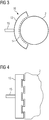
- the geometrical-constructive shape of the suction and / or blower tool body 13 is also round or rounded (cf. Fig. 3 , 5 ).
- a suction and / or blower tool body 13 with a round or rounded geometry of the object to be unpacked 2 adapted geometric-constructive shape.
- an object 2 to be unpacked has, for example, a polyhedron, a geometric-constructive shape having several flat surfaces
- the geometric-constructive shape of the suction and / or blower tool body 13 is also flat.
- a suction and / or blower tool body 13 can be used with a planar geometrical-constructive shape corresponding to the geometrical-constructive shape of the object 2 to be unpacked that has several flat surfaces.
- the suction and / or blower tool body 13 is designed to be curved or curved in accordance with the curvature of the outer contour of the object 2.
- the suction and / or blower tool body 13 surrounds (in the circumferential direction) at least part of the outer contour of the object 2.
- the suction and / or blower tool body 13 is designed in a stepped manner in accordance with the stepped outer contour of the object 2, in particular jagged or crenellated or shaped.
- the suction and / or blower tool body 13 surrounds (in the circumferential direction) at least part of the outer contour of the object 2.
- the suction and / or blower tool body 13 is designed in a ring shape in accordance with the rounding of the outer contour of the (hollow) cylindrical object 2.
- the suction and / or blower tool body 13 completely surrounds the outer contour of the object 2 (in the circumferential direction).
- the suction and / or blower tool body 13 is designed to run in a square shape in accordance with the square outer contour of the object 2.
- the suction and / or blower tool body 13 completely surrounds the outer contour of the object 2 to be unpacked (in the circumferential direction).
- the suction and / or blower tool body 13 is formed here by a plurality of suction and / or blower tool body segments 13a which are fastened to one another and each have, for example, an L shape.
- the Blower tool body 13 can also include only one (single) blower tool body segment 13a, optional blower tool body segments 13a are shown in broken lines.
- the suction and / or blower tool body 13 is designed to run in a wave-like manner in accordance with the wavy-curved outer contour of the object 2.
- the suction and / or blower tool body 13 surrounds a part of the outer contour of the object 2 to be unpacked (in the longitudinal direction).
- the suction and / or blower tool body 13 is formed here by a plurality of suction and / or blower tool body segments 13a which are fastened to one another and each have, for example, a curved course.
- the suction and / or blower tool body 13 can comprise a plurality of suction and / or blower tool body segments 13a, which are detachably attachable to one another, forming the suction and / or blower tool body 13.
- a configuration of the suction and / or blower tool body 13 that is individually adaptable or adapted in a geometrically constructive respect is possible.
- Corresponding suction and / or blower tool body segments 13a can have the same or a different geometric-constructive shape.
- Respective suction and / or blower tool body segments 13a are equipped with suitable fastening interfaces (not shown), which ensure a stable, yet detachable fastening of these to one another.
- Corresponding mounting interfaces can, for. B. enable a positive and / or non-positive attachment of respective suction and / or blower tool body segments 13a to each other.
- the suction and / or blower tool body segments 13a are equipped with at least one flow channel section (not shown).
- the flow channel sections form respective suction and / or in the attached state Blower tool body segments 13a have a flow channel (not shown) penetrating the suction and / or blower tool body 13 at least in sections.
- the flow channel communicates, on the one hand, with corresponding suction and / or blower openings 14 of the suction and / or blower tool body 13 and, on the other hand, with a respective line element 15 via which the suction and / or blower tool 13 communicates with the part of the suction and / or blower flow Suction and / or blower device 12 is connected.
- the object 2 has a dome-shaped geometric-constructive shape which has a plurality of openings.
- Object 2 can e.g. B. present as a foam body having a foam structure.
- the object 2 z. B. an artificial acetabulum or part of such.
- the suction and / or blower tool body 13 has a cannula-like or -shaped geometric-constructive elongated shape with a curved free end.
- the suction and / or blower tool body 13 can be guided through the openings in the object 2 into an interior of the object 2; the cross-sectional geometry of the suction and / or blower tool body (section) is matched to the cross-sectional geometry of the opening.
- the double arrow P1 indicates that the suction and / or blower tool body 13 can be rotatable about an axis of rotation.
- the unpacking device 4 enables the suction and / or blower tool body 13 to be brought closer to an object 2 to be unpacked and / or - in the case of several objects 2 to be unpacked - closer between objects 2 to be unpacked.
- the suction and / or Blower tool body 13 can be guided to the object 2 or, if necessary through openings provided in the object 2, into optionally existing interior spaces of the object 2.
- the unpacking device 4 comprises a storage device (not shown).
- a plurality of suction and / or blower tool bodies 13 of a given geometric-constructive shape and / or a plurality of suction and / or blower tool body segments 13a of a given geometric-constructive shape can be arranged or arranged in the storage device.
- the suction and / or blower tool bodies (segments) 13, 13a can be arranged or arranged in an orderly manner in the storage device according to geometric-constructive criteria, in particular according to the geometric dimension and / or basic geometric shape.
- the storage device can comprise a plurality of storage compartments, which are provided for the storage or storage of suction and / or blower tool bodies (segments) n 13, 13a of a certain geometrical-constructive shape, ie correspondingly adapted in their dimensions, so that the storage device as a whole is as possible has a compact structure.
- the unpacking device 4 comprises a robot 7 having at least three (different) robot axes A1-A6.
- the robot 7 is e.g. B. arranged on a bottom wall 8a of the unpacking chamber 8 bounding the unpacking chamber 8.
- the robot 7 it is also conceivable for the robot 7 to be arranged or formed on a side or ceiling wall of the unpacking chamber 8 that delimits the unpacking chamber 8.
- both standing and (laterally) hanging arrangements of robots 7 are conceivable.
- the robot 7 can be arranged in the unpacking chamber 8 so as to be stationary or movable in at least one degree of freedom of movement. If the robot 7 does not have its own movement drives, suitable movement devices (not shown) can be present on the unpacking chamber side, which enable a movement of the robot 7, in particular along a certain movement path. Corresponding movement devices can, for. B. enable a guided movement of the robot 7 along the object 2 to be unpacked or within the building module 6 containing the object 2 to be unpacked and moved into the unpacking station 1.
- the robot 7 can be defined in (pre) Unpacking positions are moved, which can be selected on the basis of the geometric-constructive shape of the object 2 to be unpacked.
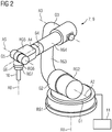
- Fig. 2 shows a schematic diagram of a robot 7 according to an embodiment, which robot 7 in the in Fig. 1 Unpacking station 1 shown can be used.
- the robot 7 is designed as an articulated or articulated arm robot and comprises a robot arm 9.
- the robot arm 9 comprises a plurality of robot members RG 1-RG7 which are connected in series and connected to one another in an articulated manner via joint elements G1-G6.
- the joint elements G1 - G6 are swivel joints.
- the articulated elements G1-G6 produce a rotatable connection of robot members RG 1-RG7 arranged (directly) adjacent to each other.
- the robot axes A1-A1 are assigned to the joint elements G1-G6 or to the robot members RG1-RG7 which are connected to one another via the joint elements G1-G6.
- the respective robot axes A1 - A6 or the joint elements G1 - G6 or the robot links RG1 - RG7 can be controlled independently of one another and accordingly can be moved independently of one another.
- the operation of the robot 7 is controlled by a control device 11 implemented in hardware and / or software.
- the robot links RG1 - RG7 are in the Fig. 2 Embodiment shown around a base (robot member RG1), a downstream carousel (robot member RG2) rotatably mounted about the robot axis A1, a swivel arm connected downstream and rotatable about the robot axis A2 (robot member RG3), one downstream of the latter about the robot axis A3 rotatably mounted cantilever (robot member RG4), a multi-axis robot hand (robot member RG5) connected downstream, rotatable about the robot axis A4, a downstream attachment device (robot member RG6) rotatably mounted about the robot axis A5 and one connected downstream, rotatable about the robot axis A6 mounted tool holder (robot link RG7).
- a robot tool could also be arranged instead of the tool holding device.
- the suction and / or blower tool 10 or the suction and / or blower tool body 13 is arranged on the (last) joint G6 or the (last) robot member RG7 forming the free end of the robot arm 9.
- the suction and / or blower tool 10 or the suction and / or blower tool body 13 can be detachably arranged or fastened on the robot axis A6 or the robot member RG7.
- suitable, in particular mechanical, fastening interfaces can be arranged or designed by the robot 7 and / or by the suction and / or blower tool 10 or the suction and / or blower tool body 13, which have a releasable Allow attachment of the suction and / or blower tool 10 or the suction and / or blower tool body 13 to the robot axis A6 or the robot member RG7.
- Detachable attachment of the suction and / or blower tool 10 or of the suction and / or blower tool body 13 to the robot axis A6 or the robot member RG7 can also be achieved in that the robot axis A6 or the robot member RG7 comprises a gripping element which for gripping the suction and / or blower tool 10 or the suction and / or blower tool body 13.
- suction and / or blower tool 10 or the suction and / or blower tool body 13 Due to the detachable arrangement or attachment of the suction and / or blower tool 10 or the suction and / or blower tool body 13 on the robot axis A6 or the robot member RG7, it is possible for a suction and / or blower tool 10 or a Suction and / or blower tool body 13 is interchangeably arranged or attached to the robot axis A6 or the robot member RG7, if necessary.
- the robot 7 can e.g. B. in a tool change mode or program provided for this purpose, be set up to carry out an automated change of a suction and / or blower tool 10 or a suction and / or blower tool body 13.
- the robot 7, ie at least the robot axis A6 or the robot member RG7, to which the suction and / or blower tool 10 or the suction and / or blower tool body 13 is detachably fastened can be suction and / or blower tools 10 or suction and / or blower tool body 13 in one of the unpacking device 4 Give assigned storage device or remove from a storage device assigned to unpacking device 4.
- the unpacking device 4 comprises a control device 1 implemented in terms of hardware and / or software.
- the control device is set up in particular to generate control information that controls the movements of the robot axes A1-A6 during operation of the robot 7.
- the control device 11 is set up, in particular taking into account the geometric-constructive shape of an object 2 to be unpacked, to control the robot 7, so that the robot 7 adopts a suction and / or blower tool body 13 with a shape adapted to at least a partial area of the geometrical-constructive shape of the object 2 to be unpacked Geometric-constructive shape and / or a plurality of suction and / or blower tool body segments 13a for the formation of a suction and / or blower tool body 13 with a geometric-constructive shape adapted to at least a portion of the geometric-constructive shape of the object 2 to be unpacked and selected for unpacking unpacked object 2 used.
- the control device 11 can also be set up to generate corresponding control information on the basis of data describing the geometric-constructive shape of the object 2 to be unpacked, in particular on the basis of construction data describing the geometric-constructive shape of the object 2 to be unpacked.
- the movements of the robot axes A1 - A6 can thus be matched to the geometrical-constructive shape or the geometrical-constructive features, ie in particular the outer and / or inner contour, any undercuts, etc., of the object 2 to be unpacked.
- Unpacking processes can be controlled individually, taking into account the geometric-constructive shape of the object 2 to be unpacked. It applies to all exemplary embodiments that the suction and / or blower tool body 13 or a corresponding suction and / or blower tool body segment 13a can be an additively manufactured object.
Landscapes
- Engineering & Computer Science (AREA)
- Chemical & Material Sciences (AREA)
- Materials Engineering (AREA)
- Manufacturing & Machinery (AREA)
- Mechanical Engineering (AREA)
- Physics & Mathematics (AREA)
- Optics & Photonics (AREA)
- Robotics (AREA)
- Ceramic Engineering (AREA)
- Inorganic Chemistry (AREA)
- Structural Engineering (AREA)
- Organic Chemistry (AREA)
- Manipulator (AREA)
- Powder Metallurgy (AREA)
- Producing Shaped Articles From Materials (AREA)
- Structures Of Non-Positive Displacement Pumps (AREA)
Description
- Die Erfindung betrifft eine Auspackeinrichtung zum Auspacken eines additiv hergestellten dreidimensionalen Objekts aus dem dieses nach Beendigung eines additiven Bauvorgangs umgebenden nicht verfestigten Baumaterial, umfassend eine Saug- und/oder Gebläseeinrichtung, welche wenigstens ein Saug- und/oder Gebläsewerkzeug mit Saug- und/oder Gebläsewerkzeugkörper umfasst.
- Additiv hergestellte dreidimensionale Objekte sind nach Beendigung des additiven Bauvorgangs bekanntermaßen von nicht verfestigtem pulverartigen bzw. -förmigen Baumaterial umgeben. Zum Auspacken der additiv hergestellten dreidimensionalen Objekte aus dem diese umgebenden Baumaterial sind Auspackeinrichtungen bekannt, welche eine Saug- und/oder Gebläseeinrichtung mit einem einen Saug- und/oder Gebläsewerkzeugkörper umfassenden Saug- und/oder Gebläsewerkzeug umfasst.
- Die geometrisch-konstruktive Gestalt entsprechender Saug- und/oder Gebläsewerkzeugkörper ist typischerweise fest vorgegeben, was im Hinblick auf das Auspacken additiv hergestellter dreidimensionaler Objekte unterschiedlicher geometrischer-konstruktiver Gestalt verbesserungswürdig ist, als bestimmte Geometrien der auszupackenden Objekte bisweilen schwer zu erreichen sein können. Die fest vorgegebene geometrisch-konstruktive Gestalt der Saug- und/oder Gebläsewerkzeugkörper kann bei Auspackvorgängen komplex, d. h. insbesondere filigran, gestalteter Objekte zudem eine Gefahr darstellen, als Objekte komplexer geometrisch-konstruktiver Gestalt durch den Saug- und/oder Gebläsewerkzeugkörper gegebenenfalls beschädigt werden können. Die
WO2010/083997 A2 und dieUS2002/0090410 A1 beschreiben beide Auspackeinrichtungen zum Auspacken eins additiv hergestellten dreidimensionalen Objekts. - Der Erfindung liegt damit die Aufgabe zugrunde, eine demgegenüber verbesserte Auspackeinrichtung zum Auspacken eines additiv hergestellten dreidimensionalen Objekts aus dem dieses nach Beendigung eines additiven Bauvorgangs umgebenden nicht verfestigten Baumaterial anzugeben.
- Die Aufgabe wird durch eine Auspackeinrichtung gemäß Anspruch 1 gelöst. Die hierzu abhängigen Ansprüche betreffen mögliche Ausführungsformen der Auspackeinrichtung.
- Die hierin beschriebene Auspackeinrichtung dient zum Auspacken eines additiv hergestellten dreidimensionalen Objekts ("Objekt") aus dem dieses nach Beendigung eines additiven Bauvorgangs umgebenden (, im Rahmen der additiven Herstellung des Objekts erfolgenden sukzessiven schichtweisen selektiven Belichtung und damit einhergehenden sukzessiven schichtweisen selektiven Verfestigung von Baumaterialschichten, verfestigbaren Baumaterial) nicht verfestigten pulverartigen bzw. -förmigen Baumaterial. Bei dem Baumaterial handelt es sich beispielsweise um ein Metallpulver; gleichwohl sind als Baumaterial auch Keramik- oder Kunststoffpulver denkbar. Unter Auspacken ist im Allgemeinen ein Entfernen von dem das jeweilige Objekt umgebenden Baumaterial zu verstehen; das jeweilige Objekt wird von dem dieses umgebenden Baumaterial "befreit".
- Die Auspackeinrichtung umfasst eine Saug- und/oder Gebläseeinrichtung. Die Saug- und/oder Gebläseeinrichtung ist zur Erzeugung einer Saug- und/oder Gebläseströmung zum Auspacken eines jeweiligen Objekts eingerichtet. Die Saug- und/oder Gebläseeinrichtung ist sonach eingerichtet, ein jeweiliges Objekts über ein Absaugen (Saugströmung) und/oder Abblasen (Gebläseströmung) von Baumaterial auszupacken. In allen Fällen lässt sich ein inertes Auspacken jeweiliger Objekte realisieren; mithin kann die verwendete Saug- und/oder Gebläseströmung inert sein.
- Die Saug- und/oder Gebläseeinrichtung umfasst wenigstens ein Saug- und/oder Gebläsewerkzeug. Das Saug- und/oder Gebläsewerkzeug umfasst einen Saug- und/oder Gebläsewerkzeugkörper. In dem Saug- und/oder Gebläsewerkzeugkörper ist typischerweise wenigstens eine, insbesondere düsenartige bzw. -förmige, Saug- und/oder Gebläseöffnung für eine Saug- und/oder Gebläseströmung gebildet. Jeweilige Saug- und/oder Gebläseöffnungen des Saug- und/oder Gebläsewerkzeugkörpers sind zweckmäßig so angeordnet bzw. ausgerichtet, dass diese dem auszupackenden Objekt zugewandt sind. Das Saug- und/oder Gebläsewerkzeug ist über ein von einer Saug- bzw. Gebläseströmung durchströmbares Leitungselement mit einem eine Saug- bzw. Gebläseströmung erzeugenden Teil der Saug- und/oder Gebläseeinrichtung verbunden. Der Saug- und/oder Gebläsewerkzeugkörper kann (zusätzlich) einen mehrere borstenartig angeordnete oder ausgebildete, insbesondere textile, Bürstenelemente umfassenden Bürstenbesatz aufweisen.
- Die geometrisch-konstruktive Gestalt, d. h. insbesondere die Abmessungen und/oder die Form bzw. Grundform, des Saug- und/oder Gebläsewerkzeugkörpers ist individuell an wenigstens einen Teilbereich der geometrisch-konstruktiven Gestalt wenigstens eines auszupackenden Objekts, gegebenenfalls die gesamte geometrisch-konstruktive Gestalt wenigstens eines auszupackenden Objekts, anpassbar bzw. angepasst. Die räumlich-körperliche äußere Gestalt des Saug- und/oder Gebläsewerkzeugkörpers entspricht sonach gezielt wenigstens einem Teilbereich der räumlich-körperlichen äußeren Gestalt des auszupackenden Objekts, gegebenenfalls der gesamten räumlich-körperlichen äußeren Gestalt des auszupackenden Objekts. Die geometrisch-konstruktive Gestalt des Saug- und/oder Gebläsewerkzeugkörpers kann auf Grundlage von die geometrisch-konstruktive Gestalt wenigstens eines auszupackenden Objekts beschreibenden Daten, insbesondere auf Grundlage von die geometrisch-konstruktive Gestalt eines auszupackenden Objekts beschreibenden Baudaten, gewählt. Es liegt eine zumindest bereichsweise an die Geometrie eines auszupackenden Objekts gezielt anpassbare bzw. angepasste Saug- und/oder Gebläsewerkzeugkörpergeometrie vor.
- Weist ein auszupackendes Objekt - wie etwa bei einem Zylinder bzw. Hohlzylinder - beispielsweise eine runde bzw. rundliche geometrisch-konstruktive Gestalt auf, ist auch die geometrisch-konstruktive Gestalt des Saug- und/oder Gebläsewerkzeugkörpers rund bzw. rundlich. In diesem Fall wird also ein Saug- und/oder Gebläsewerkzeugkörper mit einer an die runde bzw. rundliche Geometrie des auszupackenden Objekts angepassten geometrisch-konstruktiven Gestalt, d. h. ein Saug- und/oder Gebläsewerkzeugkörper mit einer der runden bzw. rundlichen geometrisch-konstruktiven Gestalt des auszupackenden Objekts entsprechenden runden bzw. rundlichen geometrisch-konstruktiven Gestalt, verwendet. Weist ein auszupackendes Objekt - wie etwa bei einem Polyeder - eine mehrere ebene Flächen aufweisende geometrisch-konstruktive Gestalt auf, ist auch die geometrisch-konstruktive Gestalt des Saug- und/oder Gebläsewerkzeugkörpers flächig. In diesem Fall wird also ein Saug- und/oder Gebläsewerkzeugkörper mit einer der mehrere ebene Flächen aufweisenden geometrisch-konstruktiven Gestalt des auszupackenden Objekts entsprechenden flächigen geometrisch-konstruktiven Gestalt verwendet. Diese Prinzipien gelten für jedwede andere geometrisch definierte bzw. nicht geometrisch definierte geometrisch-konstruktive Gestalt eines auszupackenden Objekts und der dieser zumindest bereichsweise nachempfundenen geometrisch-konstruktiven Gestalt des Saug- und/oder Gebläsewerkzeugkörpers analog.
- Der Saug- und/oder Gebläsewerkzeugkörper kann bzw. einzelne, mehrere oder sämtliche Saug- und/oder Gebläsewerkzeugkörperabschnitte können daher z. B. zumindest abschnittsweise eine zwei- oder dreidimensional geradlinig verlaufende Form bzw. Grundform und/oder zumindest abschnittsweise eine zwei- oder dreidimensional gebogen verlaufende Form bzw. Grundform aufweisen. Beispielsweise wird auf eine, gegebenenfalls zumindest abschnittsweise gebogen verlaufende, kanülenartige bzw. -förmige geometrisch-konstruktive Gestalt des Saug- und/oder Gebläsewerkzeugkörpers bzw. eines Saug- und/oder Gebläsewerkzeugkörperabschnitts verwiesen, sodass das Saug- und/oder Gebläsewerkzeugkörper bzw. ein jeweiliger Saug- und/oder Gebläsewerkzeugkörperabschnitt z. B. durch eine in einem auszupackenden Objekt vorhandene Öffnung in einen Innenraum des Objekts geführt werden kann; die Querschnittsgeometrie des Saug- und/oder Gebläsewerkzeugkörper(abschnitt)s ist an die Querschnittsgeometrie der Öffnung angepasst. Es sei an dieser Stelle nochmals zu erwähnen, dass der Saug- und/oder Gebläsewerkzeugkörper, je nach geometrisch-konstruktiver Gestalt des oder der auszupackenden Objekte, eine individuell angepasste geometrisch definierte oder geometrisch nicht definierte (freie) geometrisch-konstruktive Gestalt aufweist.
- Die Auspackeinrichtung ermöglicht es, dass der Saug- und/oder Gebläsewerkzeugkörper näher an ein auszupackendes Objekt und/oder - im Falle mehrerer auszupackender Objekte - näher zwischen benachbart angeordnete auszupackende Objekte heranzuführen. Der Saug- und/oder Gebläsewerkzeugkörper kann an das Objekt oder, gegebenenfalls durch in dem Objekt vorhandene Öffnungen, in gegebenenfalls vorhandene Innenräume des Objekts geführt werden. Der eingangs beschriebenen Schwierigkeit, wonach bestimmte Geometrien eines auszupackenden, insbesondere komplex gestalteten, Objekts aufgrund einer fest vorgegebenen geometrisch-konstruktiven Gestalt des Saug- und/oder Gebläsewerkzeugkörpers mit dem Saug- und/oder Gebläsewerkzeugkörper nur schwer zu erreichen sind, ist damit Rechnung getragen. Zudem ist das Potential einer Beschädigung bei Auspackvorgängen komplex, d. h. insbesondere filigran, gestalteter Objekte reduziert, da die geometrisch-konstruktive Gestalt des Saug- und/oder Gebläsewerkzeugkörpers der geometrisch-konstruktiven Gestalt des Objekts folgt. Insgesamt liegt eine demgegenüber verbesserte Auspackeinrichtung vor.
- Der Saug- und/oder Gebläsewerkzeugkörper kann mehrere Saug- und/oder Gebläsewerkzeugkörpersegmente umfassen, welche unter Ausbildung des Saug- und/oder Gebläsewerkzeugkörpers lösbar aneinander befestigbar oder befestigt sind. Der Saug- und/oder Gebläsewerkzeugkörper kann sonach nach dem Baukastenprinzip durch einzelne Saug- und/oder Gebläsewerkzeugkörpersegmente zusammengesetzt sein. Je nach geometrisch-konstruktiver Gestalt der den Saug- und/oder Gebläsewerkzeugkörper bildenden Saug- und/oder Gebläsewerkzeugkörpersegmente ist eine in geometrisch-konstruktiver Hinsicht beliebige, d. h. individuell anpassbare bzw. angepasste, Konfiguration des Saug- und/oder Gebläsewerkzeugkörpers möglich. Entsprechende Saug- und/oder Gebläsewerkzeugkörpersegmente können sonach eine gleiche oder eine unterschiedliche geometrisch-konstruktive Gestalt aufweisen. Durch eine beispielhafte Kombination geradlinig und gebogen verlaufender Saug- und/oder Gebläsewerkzeugkörpersegmente lässt sich z. B. eine L- oder U-Form des Saug- und/oder Gebläsewerkzeugkörpers realisieren. Durch eine weitere beispielhafte Kombination, gegebenenfalls unterschiedlich, gebogen verlaufender Saug- und/oder Gebläsewerkzeugkörpersegmente lässt sich z. B. eine Ring- oder Wellenform des Saug- und/oder Gebläsewerkzeugkörpers realisieren.
- Jeweilige Saug- und/oder Gebläsewerkzeugkörpersegmente sind typischerweise mit geeigneten Befestigungsschnittstellen ausgestattet, welche eine stabile, gleichwohl typischerweise lösbare Befestigung dieser aneinander gewährleisten. Entsprechende Befestigungsschnittstellen können z. B. eine form- und/oder kraftschlüssige Befestigung jeweiliger Saug- und/oder Gebläsewerkzeugkörpersegmente aneinander ermöglichen. Beispielhaft wird auf Klips-, Klemm-, Rast- und Schraubbefestigungen verwiesen.
- Jeweilige Saug- und/oder Gebläsewerkzeugkörpersegmente sind typischerweise mit wenigstens einem Strömungskanalabschnitt ausgestattet. Die Strömungskanalabschnitte bilden im aneinander befestigten Zustand jeweiliger Saug- und/oder Gebläsewerkzeugkörpersegmente einen den Saug- und/oder Gebläsewerkzeugkörper zumindest abschnittsweise durchsetzenden Strömungskanal. Der Strömungskanal kommuniziert einerseits mit entsprechenden Saug- und/oder Gebläseöffnungen des Saug- und/oder Gebläsewerkzeugkörpers und andererseits mit einem von einer Saug- bzw. Gebläseströmung durchströmbaren Leitungselement, über welches das Saug- und/oder Gebläsewerkzeug mit einem eine Saug- bzw. Gebläseströmung erzeugenden Teil der Saug- und/oder Gebläseeinrichtung verbunden ist.
- Bei dem Saug- und/oder Gebläsewerkzeugkörper bzw. einem entsprechenden Saug- und/oder Gebläsewerkzeugkörpersegment kann es sich zumindest abschnittsweise, gegebenenfalls insgesamt, um ein additiv hergestelltes Bauteil bzw. eine additiv hergestellte Bauteilgruppe handeln. Durch eine additive Herstellung des Saug- und/oder Gebläsewerkzeugkörper(segment)s lässt sich dieser bzw. dieses in nahezu beliebigen geometrisch-konstruktiven Gestaltungen herstellen.
- Die Auspackeinrichtung umfasst eine Speichereinrichtung. In der Speichereinrichtung sind mehrere Saug- und/oder Gebläsewerkzeugkörper gegebener geometrisch-konstruktiver Gestalt und/oder mehrere Saug- und/oder Gebläsewerkzeugkörpersegmente gegebener geometrisch-konstruktiver Gestalt anordenbar oder angeordnet. Die Speichereinrichtung dient im Sinne eines Lagers bzw. eines Magazins der Vorhaltung von Saug- und/oder Gebläsewerkzeugkörper(segmenten) gegebener geometrisch-konstruktiver Gestalt, sodass im Bedarfsfall einfach und schnell auf entsprechende Saug- und/oder Gebläsewerkzeugkörper(segmente) zugegriffen werden kann, um eine wie beschriebene an die Geometrie eines auszupackenden Objekts angepasste Saug- und/oder Gebläsewerkzeugkörpergeometrie bereitzustellen. Die Saug- und/oder Gebläsewerkzeugkörper(segmente) können in der Speichereinrichtung nach geometrisch-konstruktiven Kriterien, insbesondere nach geometrischer Dimension und/oder geometrischer Grundform, geordnet anordenbar oder angeordnet sein. In allen Fällen kann die Speichereinrichtung mehrere Speicherabteile umfassen, welche für die Speicherung bzw. Lagerung von Saug- und/oder Gebläsewerkzeugkörper(segmente)n bestimmter geometrisch-konstruktiver Gestalt vorgesehen, d. h. in ihren Abmessungen entsprechend angepasst, sind, sodass die Speichereinrichtung insgesamt einen möglichst kompakten Aufbau aufweist.
- Die Auspackeinrichtung umfasst einen wenigstens drei Roboterachsen aufweisenden Roboter, insbesondere Industrieroboter, wobei der Saug- und/oder Gebläsewerkzeugkörper an einer Roboterachse angeordnet oder ausgebildet ist. Ein entsprechender Roboter weist typischerweise wenigstens einen Roboterarm auf, welcher mehrere über Gelenkelemente gelenkig miteinander verbundene, typischerweise seriell nacheinander geschaltet angeordnete Roboterglieder umfasst. Die Roboterachsen sind typischerweise jeweiligen Robotergliedern zugeordnet. Der Roboter kann z. B. als ein Gelenk- oder Knickarmroboter mit mehreren seriell nacheinander geschaltet angeordneten, über jeweilige Gelenkelemente gelenkig miteinander verbundenen Robotergliedern ausgeführt sein. Eines, mehrere oder alle Gelenkelemente des Roboters können als Drehgelenke ausgebildet sein. Grundsätzlich kann der Roboter jedwede Art von wenigstens drei Roboterachsen aufweisender Roboter bzw. Industrieroboter sein. Das Saug- und/oder Gebläsewerkzeugkörper ist, wie erwähnt, an einer Roboterachse angeordnet oder ausgebildet. Bei der Roboterachse, an welcher das wenigstens eine Auspackwerkzeug angeordnet oder ausgebildet ist, handelt es sich typischerweise um eine Roboterachse, welche einem ein freies Ende des Roboterarms bildenden Roboterglied zugeordnet ist. Durch den Umstand, dass die Auspackeinrichtung wenigstens einen entsprechenden Roboter umfasst, ist ein voll automatisierbares bzw. voll automatisiertes Auspacken jeweiliger Objekte möglich. Es ist nicht notwendig, dass der Saug- und/oder Gebläsewerkzeugkörper manuell gehandhabt wird. Auspackvorgänge sind sowohl im Hinblick auf Automatisierbarkeit, Effizienz und Sicherheit verbessert. Der Roboter kann mehr als drei Roboterachsen, insbesondere fünf, sechs oder mehr, Roboterachsen aufweisen. Je mehr Roboterachsen der Roboter aufweist, desto größer ist seine Bewegungsfreiheit im Rahmen des Auspackens jeweiliger Objekte. Es wurde erwähnt, dass der Roboter als Gelenk- bzw. Knickarmroboter ausgeführt sein kann. Eine zweckmäßige Ausführungsform sieht eine Ausbildung des Roboters als fünf- oder sechsachsiger Gelenk- bzw. Knickarmroboter vor. Unabhängig von deren Anzahl und somit auch von der konkreten Ausführung des Roboters sind jeweilige Roboterachsen typischerweise unabhängig voneinander ansteuerbar. Die Roboterachsen sind entsprechend auch unabhängig voneinander bewegbar. Typischerweise ist jede Roboterachse in wenigstens einem Bewegungsfreiheitsgrad bewegbar.
- Der Saug- und/oder Gebläsewerkzeugkörper ist lösbar an der Roboterachse angeordnet, sodass er bedarfsweise auswechselbar an der Roboterachse angeordnet ist. Zur Realisierung einer lösbaren Befestigung des Saug- und/oder Gebläsewerkzeugkörpers können seitens des Roboters und/oder seitens des Saug- und/oder Gebläsewerkzeugkörpers geeignete, insbesondere mechanische, Befestigungsschnittstellen angeordnet oder ausgebildet sein, welche eine lösbare Befestigung des Saug- und/oder Gebläsewerkzeugkörpers an der Roboterachse ermöglichen. Eine lösbare Befestigung des Saug- und/oder Gebläsewerkzeugkörpers an der Roboterachse kann jedoch auch dadurch realisiert sein, dass die Roboterachse ein Greifelement umfasst, welches zum Greifen des Saug- und/oder Gebläsewerkzeugkörpers eingerichtet ist.
- Durch die lösbare Anordnung bzw. Befestigung des Saug- und/oder Gebläsewerkzeugkörpers an der Roboterachse ist es möglich, dass der Saug- und/oder Gebläsewerkzeugkörper bedarfsweise auswechselbar an der Roboterachse angeordnet bzw. befestigt ist. Ein Auswechselvorgang des Saug- und/oder Gebläsewerkzeugkörpers kann ebenso automatisiert erfolgen. Der Roboter kann, z. B. in einem hierfür eigens vorgesehenen Werkzeugwechselmodus bzw. -programm, eingerichtet sein, einen Wechsel eines Saug- und/oder Gebläsewerkzeugkörpers vorzunehmen. Hierbei kann der Roboter z. B. in eine Auswechselposition bewegbar sein, in welcher der Roboter selbstständig einen Wechsel eines Saug- und/oder Gebläsewerkzeugkörpers vornimmt. In der Auswechselposition kann der Roboter, d. h. wenigstens die Roboterachse, an welcher der Saug- und/oder Gebläsewerkzeugkörper lösbar zu befestigen bzw. befestigt ist, Saug- und/oder Gebläsewerkzeugkörper in eine bereits erwähnte, der Auspackeinrichtung zugeordnete Speichereinrichtung geben bzw. aus einer der Auspackeinrichtung zugeordneten Speichereinrichtung entnehmen.
- Die Auspackeinrichtung umfasst eine hard- und/oder softwaremäßig implementierte Steuereinrichtung, die zur Steuerung des Betriebs eines entsprechenden Roboters eingerichtet ist. Die Steuereinrichtung ist zur Erzeugung von die Bewegungen der Roboterachsen im Betrieb des Roboters steuernden Steuerungsinformationen eingerichtet. Die Steuereinrichtung ist eingerichtet, insbesondere unter Berücksichtigung der geometrisch-konstruktiven Gestalt eines auszupackenden Objekts, den Roboter anzusteuern, sodass dieser einen Saug- und/oder Gebläsewerkzeugkörper mit einer an wenigstens einen Teilbereich der geometrisch-konstruktiven Gestalt des auszupackenden Objekts angepassten geometrisch-konstruktiven Gestalt und/oder mehrere Saug- und/oder Gebläsewerkzeugkörpersegmente zur Ausbildung eines Saug- und/oder Gebläsewerkzeugkörpers mit einer an wenigstens einen Teilbereich der geometrisch-konstruktiven Gestalt des auszupackenden Objekts angepassten geometrisch-konstruktiven Gestalt auswählt und zum Auspacken des auszupackenden Objekts verwendet. Eine entsprechend eingerichtete Steuereinrichtung wirkt sich positiv auf die Automatisierbarkeit der mit der Auspackeinrichtung durchführbaren bzw. durchgeführten Auspackvorgänge aus.
Die Steuereinrichtung kann ferner eingerichtet sein, entsprechende Steuerungsinformationen auf Grundlage von die geometrisch-konstruktive Gestalt eines jeweils auszupackenden Objekts beschreibenden Daten, insbesondere auf Grundlage von die geometrisch-konstruktive Gestalt eines jeweils auszupackenden Objekts beschreibenden Baudaten, zu erzeugen. Die Bewegungen der Roboterachsen können sonach auf die geometrisch-konstruktive Gestalt bzw. die geometrisch-konstruktiven Merkmale, d. h. insbesondere die Außen- und/oder Innenkontur, etwaige Hinterschneidungen, etc., des auszupackenden Objekts abgestimmt sein. Auspackvorgänge können individuell unter Berücksichtigung der geometrisch-konstruktiven Gestalt eines jeweils auszupackenden Objekts gesteuert werden. Derart kann die Effizienz der mit der Auspackeinrichtung durchführbaren bzw. durchgeführten Auspackvorgänge (erheblich) gesteigert werden. - Die Erfindung betrifft neben der Auspackeinrichtung auch eine Auspackstation für eine Anlage zur additiven Herstellung dreidimensionaler Objekte. Die Auspackstation zeichnet sich dadurch aus, dass sie wenigstens eine wie beschriebene Auspackeinrichtung umfasst. Mithin gelten sämtliche Ausführungen im Zusammenhang mit der Auspackeinrichtung analog für die Auspackstation.
- Die Auspackstation kann eine, insbesondere quaderförmige, Auspackkammer umfassen, welche einen Teil einer der Auspackstation zugehörigen Gehäusekonstruktion bilden kann. Die Auspackstation ist typischerweise inertisierbar bzw. inertisiert. Der oder die der Auspackeinrichtung zugehörige(n) Roboter, sofern vorhanden, kann bzw. können an oder in einer die Auspackkammer (mit)begrenzenden Boden-, Seiten- oder Deckenwandung der Auspackkammer angeordnet oder ausgebildet sein. Grundsätzlich sind sowohl stehende als auch (seitlich) hängende Anordnungen von Robotern denkbar.
- Die Auspackeinrichtung bzw. der oder die der Auspackeinrichtung zugehörige(n) Roboter, sofern vorhanden, kann bzw. können ortsfest oder in wenigstens einem Bewegungsfreiheitsgrad bewegbar gelagert in der Auspackkammer angeordnet oder ausgebildet sein. Sofern der oder die Roboter nicht über eigene Bewegungsantriebe verfügen, können auspackkammerseitig geeignete Bewegungseinrichtungen vorhanden sein, welche eine, insbesondere entlang einer bestimmten Bewegungsbahn, geführte Bewegung der Auspackeinrichtung bzw. eines Roboters ermöglichen. Entsprechende Bewegungseinrichtungen können z. B. eine geführte Bewegung der Auspackeinrichtung bzw. eines Roboters entlang eines auszupackenden Objekts innerhalb eines ein auszupackendes Objekt enthaltenden, in die Auspackstation bewegten Baumoduls ermöglichen. Der Roboter kann dabei in (vor)definierte Auspackpositionen bewegt werden. Die Auspackpositionen können wiederum auf Grundlage der geometrisch-konstruktiven Gestalt des auszupackenden Objekts gewählt sein.
- Neben der Auspackeinrichtung und der Auspackstation betrifft die Erfindung auch eine Anlage zur additiven Herstellung dreidimensionaler Objekte. Die Anlage zeichnet sich dadurch aus dass sie wenigstens eine wie beschriebene Auspackstation umfasst. Mithin gelten sämtliche Ausführungen im Zusammenhang mit der Auspackeinrichtung sowie im Zusammenhang mit der Auspackstation analog für die Anlage.
- Neben der Auspackstation umfasst die Anlage typischerweise wenigstens eine Vorrichtung zur additiven Herstellung dreidimensionaler Objekte, d. h. beispielsweise technischer Bauteile bzw. technischer Bauteilgruppen, durch sukzessives schichtweises selektives Belichten und damit einhergehendes Verfestigen von Baumaterialschichten aus einem vermittels eines Laserstrahls verfestigbaren Baumaterial. Die selektive Verfestigung jeweiliger selektiv zu verfestigender Baumaterialschichten erfolgt auf Grundlage objektbezogener Baudaten. Entsprechende Baudaten beschreiben die geometrisch-konstruktive Gestalt des jeweils additiv herzustellenden Objekts und können beispielsweise "geslicte" CAD-Daten eines jeweiligen additiv herzustellenden Objekts beinhalten. Die Vorrichtung kann als SLM-Vorrichtung, d. h. als Vorrichtung zur Durchführung selektiver Laserschmelzverfahren (SLM-Verfahren), oder als SLS-Vorrichtung, d. h. als Vorrichtung zur Durchführung selektiver Lasersinterverfahren (SLS-Verfahren), ausgebildet sein.
- Die Erfindung ist anhand von Ausführungsbeispielen in den Zeichnungsfiguren näher erläutert. Dabei zeigen:
- Fig. 1
- eine Prinzipdarstellung einer Auspackstation gemäß einem Ausführungsbeispiel;
- Fig. 2
- eine Prinzipdarstellung eines Roboters gemäß einem Ausführungsbeispiel; und
- Fig. 3 - 8
- jeweils eine Prinzipdarstellung eines Saug- und/oder Gebläsewerkzeugs gemäß einem Ausführungsbeispiel.
-
Fig. 1 zeigt eine Prinzipdarstellung einer Auspackstation 1 gemäß einem Ausführungsbeispiel. - Die Auspackstation 1 ist einer Vorrichtung (nicht gezeigt) zur additiven Herstellung dreidimensionaler Objekte 2, d. h. insbesondere technischer Bauteile bzw. technischer Bauteilgruppen, zugeordnet. Die Vorrichtung ist zur additiven Herstellung dreidimensionaler Objekte 2 durch sukzessives schichtweises selektives Belichten und damit einhergehendes Verfestigen von Baumaterialschichten aus einem verfestigbaren Baumaterial 3, d. h. z. B. eines Metallpulvers, vermittels eines Laserstrahls eingerichtet. Die selektive Verfestigung jeweiliger selektiv zu verfestigender Baumaterialschichten erfolgt auf Grundlage von objektbezogenen Baudaten. Entsprechende Baudaten beschreiben die geometrisch-konstruktive Gestalt eines jeweils additiv herzustellenden Objekts 2.
- Die Vorrichtung wie auch die dieser zugeordnete Auspackstation 1 bilden Bestandteile einer übergeordneten Anlage (nicht gezeigt) zur additiven Herstellung dreidimensionaler Objekte 2.
- Die Auspackstation 1 umfasst eine Auspackeinrichtung 4. Die Auspackeinrichtung 4 ist in einer mit einem Inertgas, wie z. B. Argon, Stickstoff, etc., inertisierbaren bzw. inertisierten Auspackkammer 8 der Auspackstation 1 angeordnet. Die Auspackkammer 8 kann einen Teil einer der Auspackstation 1 zugehörigen Gehäusekonstruktion (nicht näher bezeichnet) bilden.
- Die Auspackeinrichtung 4 ist zum Auspacken eines additiv hergestellten dreidimensionalen Objekts 2 aus dem dieses nach Beendigung eines additiven Bauvorgangs umgebenden nicht verfestigten pulverartigen bzw. -förmigen Baumaterial 3 eingerichtet. In dem in
Fig. 1 gezeigten Ausführungsbeispiel ist das Objekt 2 nebst dem dieses umgebenden Baumaterial 3 in einem Bauraum 5 bzw. in einer Baukammer eines in die Auspackstation 1 bewegten Baumoduls 6 angeordnet. - Die Auspackeinrichtung 4 umfasst eine Saug- und/oder Gebläseeinrichtung 12. Die Saug- und/oder Gebläseeinrichtung 12 ist zur Erzeugung einer Saug- und/oder Gebläseströmung zum Auspacken eines jeweiligen Objekts 2 eingerichtet. Die Auspackeinrichtung 4 ist sonach eingerichtet, das Objekt 2 über ein Absaugen (Saugströmung) und/oder ein Abblasen (Gebläseströmung) von Baumaterial auszupacken. Die verwendete Saug- und/oder Gebläseströmung kann inert sein; bei der Saug- und/oder Gebläseströmung kann es sich z. B. um eine Argon- oder Stickstoffströmung handeln.
- Die Saug- und/oder Gebläseeinrichtung 12 umfasst ein Saug- und/oder Gebläsewerkzeug 10. Das Saug- und/oder Gebläsewerkzeug 10 umfasst einen Saug- und/oder Gebläsewerkzeugkörper 13. In dem Saug- und/oder Gebläsewerkzeugkörper 13 ist wenigstens eine, insbesondere düsenartige bzw. -förmige, Saug- und/oder Gebläseöffnung 14 für eine Saug- und/oder Gebläseströmung ausgebildet. Das Saug- und/oder Gebläsewerkzeug 10 ist über ein von einer Saug- bzw. Gebläseströmung durchströmbares Leitungselement 15 mit einem eine Saug- bzw. Gebläseströmung erzeugenden Teil der Saug- und/oder Gebläseeinrichtung 12 verbunden. Der Saug- und/oder Gebläsewerkzeugkörper 13 kann (zusätzlich) einen mehrere borstenartig angeordnete oder ausgebildete, insbesondere textile, Bürstenelemente umfassenden Bürstenbesatz (nicht gezeigt) aufweisen.
- Wie insbesondere anhand der in den
Fig. 3 - 8 gezeigten Ausführungsbeispiele jeweiliger Saug- und/oder Gebläsewerkzeugkörper 13 ersichtlich ist, ist die geometrisch-konstruktive Gestalt, d. h. insbesondere die Abmessungen und/oder die Form bzw. Grundform, des Saug- und/oder Gebläsewerkzeugkörpers 13 an wenigstens einen Teilbereich der geometrisch-konstruktiven Gestalt des jeweils auszupackenden Objekts 2 bzw. an die gesamte geometrisch-konstruktive Gestalt des jeweils auszupackenden Objekts 2 anpassbar bzw. angepasst. Die räumlich-körperliche äußere Gestalt des Saug- und/oder Gebläsewerkzeugkörpers 13 entspricht sonach zumindest bereichsweise der gesamten räumlich-körperlichen äußeren Gestalt des jeweils auszupackenden Objekts 2. Die geometrisch-konstruktive Gestalt des Saug- und/oder Gebläsewerkzeugkörpers kann auf Grundlage von die geometrisch-konstruktive Gestalt des jeweils auszupackenden Objekts 2 beschreibenden Daten, insbesondere auf Grundlage von die geometrisch-konstruktive Gestalt des jeweils auszupackenden Objekts 2 beschreibenden Baudaten, gewählt sein. - Weist ein auszupackendes Objekt 2 - wie etwa bei einem Zylinder bzw. Hohlzylinder - beispielsweise eine runde bzw. rundliche geometrisch-konstruktive Gestalt auf, ist auch die geometrisch-konstruktive Gestalt des Saug- und/oder Gebläsewerkzeugkörpers 13 rund bzw. rundlich (vgl.
Fig. 3 ,5 ). In diesem Fall kann bzw. wird ein Saug- und/oder Gebläsewerkzeugkörper 13 mit einer an die runde bzw. rundliche Geometrie des auszupackenden Objekts 2 angepassten geometrisch-konstruktiven Gestalt verwendet. Weist ein auszupackendes Objekt 2 - wie etwa bei einem Polyeder - eine mehrere ebene Flächen aufweisende geometrisch-konstruktive Gestalt auf, ist auch die geometrisch-konstruktive Gestalt des Saug- und/oder Gebläsewerkzeugkörpers 13 flächig. In diesem Fall kann bzw. wird ein Saug- und/oder Gebläsewerkzeugkörper 13 mit einer der mehrere ebene Flächen aufweisenden geometrisch-konstruktiven Gestalt des auszupackenden Objekts 2 entsprechenden flächigen geometrisch-konstruktiven Gestalt verwendet. - In dem in
Fig. 3 in einer Aufsicht gezeigten Ausführungsbeispiel eines Saug- und/oder Gebläsewerkzeugkörpers 13 ist der Saug- und/oder Gebläsewerkzeugkörper 13 entsprechend der Wölbung der äußeren Kontur des Objekts 2 gebogen bzw. gewölbt verlaufend ausgebildet. Der Saug- und/oder Gebläsewerkzeugkörper 13 umgibt (in Umfangsrichtung) wenigstens einen Teil der äußeren Kontur des Objekts 2. - In dem in
Fig. 4 in einer Aufsicht gezeigten Ausführungsbeispiel eines Saug- und/oder Gebläsewerkzeugkörpers 13 ist der Saug- und/oder Gebläsewerkzeugkörper 13 entsprechend der, insbesondere zacken- oder zinnenartig bzw. -förmig, gestuften äußeren Kontur des Objekts 2 gestuft verlaufend ausgebildet. Der Saug- und/oder Gebläsewerkzeugkörper 13 umgibt (in Umfangsrichtung) wenigstens einen Teil der äußeren Kontur des Objekts 2. - In dem in
Fig. 5 in einer Perspektive gezeigten Ausführungsbeispiel eines Saug- und/oder Gebläsewerkzeugkörpers 13 ist der Saug- und/oder Gebläsewerkzeugkörper 13 entsprechend der Rundung der äußeren Kontur des (hohl)zylindrischen Objekts 2 ringförmig verlaufend ausgebildet. Der Saug- und/oder Gebläsewerkzeugkörper 13 umgibt die äußere Kontur des Objekts 2 (in Umfangsrichtung) vollständig. - In dem in
Fig. 6 in einer Aufsicht gezeigten Ausführungsbeispiel eines Saug- und/oder Gebläsewerkzeugkörpers 13 ist der Saug- und/oder Gebläsewerkzeugkörper 13 entsprechend der viereckigen äußeren Kontur des Objekts 2 viereckförmig verlaufend ausgebildet. Der Saug- und/oder Gebläsewerkzeugkörper 13 umgibt die äußere Kontur des auszupackenden Objekts 2 (in Umfangsrichtung) vollständig. Der Saug- und/oder Gebläsewerkzeugkörper 13 ist hier durch mehrere aneinander befestigte, jeweils beispielhaft eine L-Form aufweisende Saug- und/oder Gebläsewerkzeugkörpersegmente 13a gebildet. Zur Erläuterung, dass der Gebläsewerkzeugkörper 13 auch nur ein (einziges) Gebläsewerkzeugkörpersegment 13a umfassen kann, sind optionale Gebläsewerkzeugkörpersegmente 13a strichliert dargestellt. - In dem in
Fig. 7 in einer Aufsicht gezeigten Ausführungsbeispiel eines Saug- und/oder Gebläsewerkzeugkörpers 13 ist der Saug- und/oder Gebläsewerkzeugkörper 13 entsprechend der wellenförmig gebogenen äußeren Kontur des Objekts 2 wellenförmig gebogen verlaufend ausgebildet. Der Saug- und/oder Gebläsewerkzeugkörper 13 umgibt einen Teil der äußeren Kontur des auszupackenden Objekts 2 (in Längsrichtung). Der Saug- und/oder Gebläsewerkzeugkörper 13 ist hier durch mehrere aneinander befestigte, jeweils beispielhaft einen gebogenen Verlauf aufweisende Saug- und/oder Gebläsewerkzeugkörpersegmente 13a gebildet. - Anhand der in den
Fig. 6, 7 gezeigten Ausführungsbeispiele lässt sich erkennen, dass der Saug- und/oder Gebläsewerkzeugkörper 13 mehrere Saug- und/oder Gebläsewerkzeugkörpersegmente 13a umfassen kann, welche unter Ausbildung des Saug- und/oder Gebläsewerkzeugkörpers 13 lösbar aneinander befestigbar bzw. befestigt sind. Je nach geometrisch-konstruktiver Gestalt der den Saug- und/oder Gebläsewerkzeugkörper 13 bildenden Saug- und/oder Gebläsewerkzeugkörpersegmente 13a ist eine in geometrisch-konstruktiver Hinsicht individuell anpassbare bzw. angepasste Konfiguration des Saug- und/oder Gebläsewerkzeugkörpers 13 möglich. Entsprechende Saug- und/oder Gebläsewerkzeugkörpersegmente 13a können eine gleiche oder eine unterschiedliche geometrisch-konstruktive Gestalt aufweisen. - Jeweilige Saug- und/oder Gebläsewerkzeugkörpersegmente 13a sind mit geeigneten Befestigungsschnittstellen (nicht gezeigt) ausgestattet, welche eine stabile, gleichwohl lösbare Befestigung dieser aneinander gewährleisten. Entsprechende Befestigungsschnittstellen können z. B. eine form- und/oder kraftschlüssige Befestigung jeweiliger Saug- und/oder Gebläsewerkzeugkörpersegmente 13a aneinander ermöglichen. Beispielhaft wird auf Klips-, Klemm-, Rast- und Schraubbefestigungen verwiesen.
- Die Saug- und/oder Gebläsewerkzeugkörpersegmente 13a sind mit wenigstens einem Strömungskanalabschnitt (nicht gezeigt) ausgestattet. Die Strömungskanalabschnitte bilden im aneinander befestigten Zustand jeweiliger Saug- und/oder Gebläsewerkzeugkörpersegmente 13a einen den Saug- und/oder Gebläsewerkzeugkörper 13 zumindest abschnittsweise durchsetzenden Strömungskanal (nicht gezeigt). Der Strömungskanal kommuniziert einerseits mit entsprechenden Saug- und/oder Gebläseöffnungen 14 des Saug- und/oder Gebläsewerkzeugkörpers 13 und andererseits mit einem jeweiligen Leitungselement 15, über welches das Saug- und/oder Gebläsewerkzeug 13 mit dem eine Saug- bzw. Gebläseströmung erzeugenden Teil der Saug- und/oder Gebläseeinrichtung 12 verbunden ist.
- Anhand der in den
Fig. 3 - 7 gezeigten Ausführungsbeispiele ist ersichtlich, dass ein konstanter Abstand zwischen dem Saug- und/oder Gebläsewerkzeugkörper 13, d. h. insbesondere dem dem Objekt 2 zugewandten Saug- und/oder Gebläsewerkzeugkörperabschnitt, welcher typischerweise jeweilige Saug- und/oder Gebläseöffnungen 14 aufweist, und dem Objekt 2 möglich sein kann. Wenngleich explizit nur inFig. 3 gezeigt, sind entsprechende Saug- und/oder Gebläseöffnungen 14 selbstverständlich bei allen Ausführungsbeispielen vorhanden. - In dem in
Fig. 8 in einer Schnittansicht gezeigten Ausführungsbeispiel weist das Objekt 2 eine mehrere Öffnungen aufweisende kalottenförmige geometrisch-konstruktive Gestalt auf. Das Objekt 2 kann z. B. als ein eine Schaumstruktur aufweisender Schaumkörper vorliegen. Konkret kann es sich bei dem Objekt 2 z. B. um eine künstliche Hüftpfanne bzw. um einen Teil einer solchen handeln. Der Saug- und/oder Gebläsewerkzeugkörper 13 weist eine kanülenartige bzw. -förmige geometrisch-konstruktive längliche Gestalt mit einem gebogenen freien Ende auf. Das Saug- und/oder Gebläsewerkzeugkörper 13 kann durch die in dem Objekt 2 vorhandenen Öffnungen in einen Innenraum des Objekts 2 geführt werden; die Querschnittsgeometrie des Saug- und/oder Gebläsewerkzeugkörper(abschnitt)s ist an die Querschnittsgeometrie der Öffnung angepasst. Durch den Doppelpfeil P1 ist angedeutet, dass der Saug- und/oder Gebläsewerkzeugkörper 13 um eine Rotationsachse rotierbar sein kann. - Aus den Ausführungen im Zusammenhang mit den in den
Fig. 3 - 8 gezeigten Ausführungsbeispielen ergibt sich, dass es die Auspackeinrichtung 4 ermöglicht, den Saug- und/oder Gebläsewerkzeugkörper 13 näher an ein auszupackendes Objekt 2 und/oder - im Falle mehrerer auszupackender Objekte 2 - näher zwischen benachbart angeordnete auszupackende Objekte 2 heranzuführen. Der Saug- und/oder Gebläsewerkzeugkörper 13 kann an das Objekt 2 oder, gegebenenfalls durch in dem Objekt 2 vorhandene Öffnungen, in gegebenenfalls vorhandene Innenräume des Objekts 2 geführt werden. - Die Auspackeinrichtung 4 umfasst eine Speichereinrichtung (nicht gezeigt). In der Speichereinrichtung sind mehrere Saug- und/oder Gebläsewerkzeugkörper 13 gegebener geometrisch-konstruktiver Gestalt und/oder mehrere Saug- und/oder Gebläsewerkzeugkörpersegmente 13a gegebener geometrisch-konstruktiver Gestalt anordenbar bzw. angeordnet. Die Saug- und/oder Gebläsewerkzeugkörper(segmente) 13, 13a können in der Speichereinrichtung nach geometrisch-konstruktiven Kriterien, insbesondere nach geometrischer Dimension und/oder geometrischer Grundform, geordnet anordenbar bzw. angeordnet sein. Die Speichereinrichtung kann mehrere Speicherabteile umfassen, welche für die Speicherung bzw. Lagerung von Saug- und/oder Gebläsewerkzeugkörper(segmente)n 13, 13a bestimmter geometrisch-konstruktiver Gestalt vorgesehen, d. h. in ihren Abmessungen entsprechend angepasst, sind, sodass die Speichereinrichtung insgesamt einen möglichst kompakten Aufbau aufweist.
Anhand vonFig. 1 ist ersichtlich, dass die Auspackeinrichtung 4 einen wenigstens drei (unterschiedliche) Roboterachsen A1 - A6 aufweisenden Roboter 7 umfasst. Der Roboter 7 ist z. B. auf einer die Auspackkammer 8 bodenseitig begrenzenden Bodenwandung 8a der Auspackkammer 8 angeordnet. Denkbar ist es jedoch auch, dass der Roboter 7 an einer die Auspackkammer 8 (mit)begrenzenden Seiten- oder Deckenwandung der Auspackkammer 8 angeordnet oder ausgebildet ist. Grundsätzlich sind sowohl stehende als auch (seitlich) hängende Anordnungen von Robotern 7 denkbar. - Der Roboter 7 kann ortsfest oder in wenigstens einem Bewegungsfreiheitsgrad bewegbar gelagert in der Auspackkammer 8 angeordnet sein. Sofern der Roboter 7 nicht über eigene Bewegungsantriebe verfügt, können auspackkammerseitig geeignete Bewegungseinrichtungen (nicht gezeigt) vorhanden sein, welche eine, insbesondere entlang einer bestimmten Bewegungsbahn, geführte Bewegung des Roboters 7 ermöglichen. Entsprechende Bewegungseinrichtungen können z. B. eine geführte Bewegung des Roboters 7 entlang des auszupackenden Objekts 2 bzw. innerhalb des das auszupackende Objekt 2 enthaltenden, in die Auspackstation 1 bewegten Baumoduls 6 ermöglichen. Der Roboter 7 kann dabei in (vor)definierte Auspackpositionen bewegt werden, welche auf Grundlage der geometrisch-konstruktiven Gestalt des auszupackenden Objekts 2 gewählt sein können.
-
Fig. 2 zeigt eine Prinzipdarstellung eines Roboters 7 gemäß einem Ausführungsbeispiel, welcher Roboter 7 in der inFig. 1 gezeigten Auspackstation 1 verwendet werden kann. - Der Roboter 7 ist als Gelenk- oder Knickarmroboter ausgeführt und umfasst einen Roboterarm 9. Der Roboterarm 9 umfasst mehrere seriell nacheinander geschaltet angeordnete, über Gelenkelemente G1 - G6 gelenkig miteinander verbundene Roboterglieder RG 1 - RG7. Bei den Gelenkelementen G1 - G6 handelt es sich um Drehgelenke. Die Gelenkelemente G1 - G6 stellen eine drehbare Verbindung jeweils (unmittelbar) benachbart angeordneter Roboterglieder RG 1 - RG7 her. Ersichtlich sind die Roboterachsen A1 - A1 den Gelenkelementen G1 - G6 bzw. den über die Gelenkelemente G1 - G6 miteinander verbundenen Robotergliedern RG1 - RG7 zugeordnet.
- Die jeweiligen Roboterachsen A1 - A6 bzw. die Gelenkelemente G1 - G6 bzw. die Roboterglieder RG1 - RG7 sind unabhängig voneinander ansteuerbar und entsprechend unabhängig voneinander bewegbar. Die Steuerung der Bewegungen der Roboterglieder RG1 - RG7, d. h. die Steuerung des Betriebs des Roboters 7, erfolgt über eine hard- und/oder softwaremäßig implementierte Steuereinrichtung 11.
- Bei den Robotergliedern RG1 - RG7 handelt es sich in dem in
Fig. 2 gezeigten Ausführungsbeispiel um eine Basis (Roboterglied RG1), ein dieser nachgeschaltetes, um die Roboterachse A1 drehbar gelagertes Karussell (Roboterglied RG2), eine diesem nachgeschaltete, um die Roboterachse A2 drehbar gelagerte Schwinge (Roboterglied RG3), einen dieser nachgeschaltete, um die Roboterachse A3 drehbar gelagerten Ausleger (Roboterglied RG4), eine diesem nachgeschaltete, um die Roboterachse A4 drehbar gelagerte mehrachsige Roboterhand (Roboterglied RG5), eine dieser nachgeschaltete, um die Roboterachse A5 drehbar gelagerte Befestigungseinrichtung (Roboterglied RG6) sowie eine dieser nachgeschaltete, um die Roboterachse A6 drehbar gelagerte Werkzeugaufnahmeeinrichtung (Roboterglied RG7). Anstelle der Werkzeugaufnahmeeinrichtung könnte auch ein Roboterwerkzeug angeordnet sein. - An dem (letzten) Gelenk G6 bzw. dem das freie Ende des Roboterarms 9 bildenden (letzten) Roboterglied RG7 ist das Saug- und/oder Gebläsewerkzeug 10 bzw. der Saug- und/oder Gebläsewerkzeugkörper 13 angeordnet.
- Das Saug- und/oder Gebläsewerkzeug 10 bzw. der Saug- und/oder Gebläsewerkzeugkörper 13 kann lösbar an der Roboterachse A6 bzw. dem Roboterglied RG7 angeordnet bzw. befestigt sein. Zur Realisierung einer lösbaren Befestigung können seitens der Roboters 7 und/oder seitens des Saug- und/oder Gebläsewerkzeugs 10 bzw. des Saug- und/oder Gebläsewerkzeugkörpers 13 geeignete, insbesondere mechanische, Befestigungsschnittstellen (nicht gezeigt) angeordnet oder ausgebildet sein, welche eine lösbare Befestigung des Saug- und/oder Gebläsewerkzeugs 10 bzw. des Saug- und/oder Gebläsewerkzeugkörpers 13 an der Roboterachse A6 bzw. dem Roboterglied RG7 ermöglichen. Eine lösbare Befestigung des Saug- und/oder Gebläsewerkzeugs 10 bzw. des Saug- und/oder Gebläsewerkzeugkörpers 13 an der Roboterachse A6 bzw. dem Roboterglied RG7 kann auch dadurch realisiert sein, dass die Roboterachse A6 bzw. das Roboterglied RG7 ein Greifelement umfasst, welches zum Greifen des Saug- und/oder Gebläsewerkzeugs 10 bzw. des Saug- und/oder Gebläsewerkzeugkörpers 13 eingerichtet ist.
- Durch die lösbare Anordnung bzw. Befestigung des Saug- und/oder Gebläsewerkzeugs 10 bzw. des Saug- und/oder Gebläsewerkzeugkörpers 13 an der Roboterachse A6 bzw. dem Roboterglied RG7 ist es möglich, dass ein Saug- und/oder Gebläsewerkzeug 10 bzw. ein Saug- und/oder Gebläsewerkzeugkörper 13 bedarfsweise auswechselbar an der Roboterachse A6 bzw. dem Roboterglied RG7 angeordnet bzw. befestigt ist. Der Roboter 7 kann, z. B. in einem hierfür eigens vorgesehenen Werkzeugwechselmodus bzw. -programm, eingerichtet sein, einen automatisierten Wechsel eines Saug- und/oder Gebläsewerkzeugs 10 bzw. eines Saug- und/oder Gebläsewerkzeugkörpers 13 vorzunehmen. Hierbei kann der Roboter 7, d. h. insbesondere die Roboterachse A6 bzw. das Roboterglied RG7, z. B. in eine Auswechselposition bewegbar sein, in welcher der Roboter 7 selbstständig einen Werkzeugwechsel vornimmt. In der Auswechselposition kann der Roboter 7, d. h. wenigstens die Roboterachse A6 bzw. das Roboterglied RG7, an welcher das Saug- und/oder Gebläsewerkzeug 10 bzw. der Saug- und/oder Gebläsewerkzeugkörper 13 lösbar zu befestigen bzw. befestigt ist, Saug- und/oder Gebläsewerkzeuge 10 bzw. Saug- und/oder Gebläsewerkzeugkörper 13 in eine der Auspackeinrichtung 4 zugeordnete Speichereinrichtung geben bzw. aus einer der Auspackeinrichtung 4 zugeordneten Speichereinrichtung entnehmen.
Wie erwähnt, umfasst die Auspackeinrichtung 4 eine hard- und/oder softwaremäßig implementierte Steuereinrichtung 1. Die Steuereinrichtung ist insbesondere zur Erzeugung von die Bewegungen der Roboterachsen A1 - A6 im Betrieb des Roboters 7 steuernden Steuerungsinformationen eingerichtet. Die Steuereinrichtung 11 ist eingerichtet, insbesondere unter Berücksichtigung der geometrisch-konstruktiven Gestalt eines auszupackenden Objekts 2, den Roboter 7 anzusteuern, sodass dieser einen Saug- und/oder Gebläsewerkzeugkörper 13 mit einer an wenigstens einen Teilbereich der geometrisch-konstruktiven Gestalt des auszupackenden Objekts 2 angepassten geometrisch-konstruktiven Gestalt und/oder mehrere Saug- und/oder Gebläsewerkzeugkörpersegmente 13a zur Ausbildung eines Saug- und/oder Gebläsewerkzeugkörpers 13 mit einer an wenigstens einen Teilbereich der geometrisch-konstruktiven Gestalt des auszupackenden Objekts 2 angepassten geometrisch-konstruktiven Gestalt auswählt und zum Auspacken des auszupackenden Objekts 2 verwendet.
Die Steuereinrichtung 11 kann ferner eingerichtet sein, entsprechende Steuerungsinformationen auf Grundlage von die geometrisch-konstruktive Gestalt des jeweils auszupackenden Objekts 2 beschreibenden Daten, insbesondere auf Grundlage von die geometrisch-konstruktive Gestalt des jeweils auszupackenden Objekts 2 beschreibenden Baudaten, zu erzeugen. Die Bewegungen der Roboterachsen A1 - A6 können sonach auf die geometrisch-konstruktive Gestalt bzw. die geometrisch-konstruktiven Merkmale, d. h. insbesondere die Außen- und/oder Innenkontur, etwaige Hinterschneidungen, etc., des auszupackenden Objekts 2 abgestimmt sein. Auspackvorgänge können individuell unter Berücksichtigung der geometrisch-konstruktiven Gestalt des jeweils auszupackenden Objekts 2 gesteuert werden.
Für alle Ausführungsbeispiele gilt, dass es sich bei dem Saug- und/oder Gebläsewerkzeugkörper 13 bzw. einem entsprechenden Saug- und/oder Gebläsewerkzeugkörpersegment 13a um ein additiv hergestelltes Objekt handeln kann.
Claims (12)
- Auspackeinrichtung (4) zum Auspacken eines additiv hergestellten dreidimensionalen Objekts (2) aus dem dieses nach Beendigung eines additiven Bauvorgangs umgebenden nicht verfestigten Baumaterial (3), umfassend eine Saug- und/oder Gebläseeinrichtung (12), welche wenigstens ein Saug- und/oder Gebläsewerkzeug (10) mit einem Saug- und/oder Gebläsewerkzeugkörper (12) umfasst, wobei die geometrisch-konstruktive Gestalt des Saug- und/oder Gebläsewerkzeugkörpers (13) an wenigstens einen Teilbereich der geometrisch-konstruktiven Gestalt wenigstens eines auszupackenden additiv hergestellten dreidimensionalen Objekts (2) anpassbar oder angepasst ist,
umfassend eine Speichereinrichtung, wobei in der Speichereinrichtung mehrere Saug- und/oder Gebläsewerkzeugkörper (13) gegebener geometrisch-konstruktiver Gestalt und/oder mehrere Saug- und/oder Gebläsewerkzeugkörpersegmente (13a) gegebener geometrisch-konstruktiver Gestalt anordenbar oder angeordnet sind, wobei
die Auspackeinrichtung (4) einen wenigstens drei Roboterachsen (A1 - A6) aufweisenden Roboter (7), insbesondere Industrieroboter, umfasst, wobei der Saug- und/oder Gebläsewerkzeugkörper (13) an einer Roboterachse (A6) angeordnet oder ausgebildet ist, wobei
der Saug- und/oder Gebläsewerkzeugkörper (13) lösbar an der Roboterachse (A6), angeordnet ist, sodass er bedarfsweise auswechselbar an der Roboterachse (A6) angeordnet ist, wobei
eine Steuereinrichtung (11) vorhanden ist, welche zur Erzeugung von die Bewegungen der Roboterachsen (A1 - A6) im Betrieb des Roboters (7) steuernden Steuerungsinformationen eingerichtet ist, wobei die Steuereinrichtung (11) eingerichtet ist, insbesondere unter Berücksichtigung der geometrisch-konstruktiven Gestalt eines auszupackenden additiv hergestellten dreidimensionalen Objekts (2), den Roboter (7) anzusteuern, sodass dieser einen Saug- und/oder Gebläsewerkzeugkörper (13) mit einer an wenigstens einen Teilbereich der geometrisch-konstruktiven Gestalt des auszupackenden additiv hergestellten dreidimensionalen Objekts (2) angepassten geometrisch-konstruktiven Gestalt und/oder mehrere Saug- und/oder Gebläsewerkzeugkörpersegmente (13a) zur Ausbildung eines Saug- und/oder Gebläsewerkzeugkörpers (13) mit einer an wenigstens einen Teilbereich der geometrisch-konstruktiven Gestalt des auszupackenden additiv hergestellten dreidimensionalen Objekts (2) angepassten geometrisch-konstruktiven Gestalt auswählt und zum Auspacken des auszupackenden additiv hergestellten dreidimensionalen Objekts (2) verwendet. - Auspackeinrichtung nach Anspruch 1, dadurch gekennzeichnet, dass der Saug- und/oder Gebläsewerkzeugkörper (13) zumindest abschnittsweise eine zwei- oder dreidimensional geradlinig verlaufende Grundform und/oder zumindest abschnittsweise eine zwei- oder dreidimensional gebogen verlaufende Grundform und/oder aufweist.
- Auspackeinrichtung nach Anspruch 1 oder 2, dadurch gekennzeichnet, dass die geometrisch-konstruktive Gestalt des Saug- und/oder Gebläsewerkzeugkörpers (13) auf Grundlage von die geometrisch-konstruktive Gestalt wenigstens eines auszupackenden additiv hergestellten dreidimensionalen Objekts (2) beschreibenden Daten, insbesondere auf Grundlage von die geometrisch-konstruktive Gestalt eines auszupackenden additiv hergestellten dreidimensionalen Objekts (2) beschreibenden Baudaten, gewählt ist.
- Auspackeinrichtung nach einem der vorhergehenden Ansprüche, dadurch gekennzeichnet, dass der Saug- und/oder Gebläsewerkzeugkörper (13) mehrere Saug- und/oder Gebläsewerkzeugkörpersegmente (13a) umfasst, welche unter Ausbildung des Saug- und/oder Gebläsewerkzeugkörpers (13) lösbar aneinander befestigbar oder befestigt sind.
- Auspackeinrichtung nach Anspruch 4, dadurch gekennzeichnet, dass wenigstens zwei Saug- und/oder Gebläsewerkzeugkörpersegmente (13a) eine gleiche oder eine unterschiedliche geometrisch-konstruktive Gestalt aufweisen.
- Auspackeinrichtung nach einem der vorhergehenden Ansprüche, dadurch gekennzeichnet, dass die Saug- und/oder Gebläsewerkzeugkörper (13) und/oder die Saug- und/oder Gebläsewerkzeugkörpersegmente (13a) in der Speichereinrichtung nach geometrisch-konstruktiven Kriterien, insbesondere nach geometrischer Dimension und/oder geometrischer Grundform, geordnet anordenbar oder angeordnet sind.
- Auspackeinrichtung nach einem der vorhergehenden Ansprüche, gekennzeichnet durch eine Steuereinrichtung (11), welche zur Erzeugung von die Bewegungen der Roboterachsen (A1 - A6) im Betrieb des Roboters (7) steuernden Steuerungsinformationen eingerichtet ist, wobei die Steuereinrichtung (11) eingerichtet ist, die Steuerungsinformationen auf Grundlage von die geometrisch-konstruktive Gestalt wenigstens eines auszupackenden additiv hergestellten dreidimensionalen Objekts (2) beschreibenden Daten, insbesondere auf Grundlage von die geometrisch-konstruktive Gestalt wenigstens eines auszupackenden additiv hergestellten dreidimensionalen Objekts (2) beschreibenden Baudaten, zu erzeugen.
- Auspackeinrichtung nach einem der vorhergehenden Ansprüche, dadurch gekennzeichnet, dass der Saug- und/oder Gebläsewerkzeugkörper (13) zumindest abschnittsweise ein additiv hergestelltes Bauteil bzw. eine additiv hergestellte Bauteilgruppe ist.
- Auspackstation (1) für eine Anlage zur additiven Herstellung dreidimensionaler Objekte (2), dadurch gekennzeichnet, dass sie wenigstens eine Auspackeinrichtung (4) nach einem der vorhergehenden Ansprüche umfasst.
- Auspackstation nach Anspruch 9, gekennzeichnet durch eine, insbesondere quaderförmige, Auspackkammer (8), wobei die Auspackeinrichtung (4) an oder in einer die Auspackkammer (8) begrenzenden Boden-, Seiten- oder Deckenwandung angeordnet oder ausgebildet ist.
- Auspackstation nach Anspruch 9 oder 10, dadurch gekennzeichnet, dass die Auspackeinrichtung (4) ortsfest oder in wenigstens einem Bewegungsfreiheitsgrad bewegbar gelagert in der Auspackkammer (8) angeordnet oder ausgebildet ist
- Anlage zur additiven Herstellung dreidimensionaler Objekte (2), dadurch gekennzeichnet, dass sie wenigstens eine Auspackstation (1) nach einem der Ansprüche 9 bis 11 umfasst.
Applications Claiming Priority (1)
| Application Number | Priority Date | Filing Date | Title |
|---|---|---|---|
| DE102016121775.1A DE102016121775A1 (de) | 2016-11-14 | 2016-11-14 | Auspackeinrichtung zum Auspacken eines additiv hergestellten dreidimensionalen Objekts aus dem dieses umgebende Baumaterial |
Publications (2)
| Publication Number | Publication Date |
|---|---|
| EP3321070A1 EP3321070A1 (de) | 2018-05-16 |
| EP3321070B1 true EP3321070B1 (de) | 2020-06-24 |
Family
ID=59677063
Family Applications (1)
| Application Number | Title | Priority Date | Filing Date |
|---|---|---|---|
| EP17186476.2A Active EP3321070B1 (de) | 2016-11-14 | 2017-08-16 | Auspackeinrichtung zum auspacken eines additiv hergestellten dreidimensionalen objekts aus dem dieses umgebenden baumaterial |
Country Status (5)
| Country | Link |
|---|---|
| US (1) | US10828835B2 (de) |
| EP (1) | EP3321070B1 (de) |
| JP (2) | JP2018080392A (de) |
| CN (1) | CN108068341A (de) |
| DE (1) | DE102016121775A1 (de) |
Families Citing this family (22)
| Publication number | Priority date | Publication date | Assignee | Title |
|---|---|---|---|---|
| US10406751B2 (en) * | 2017-04-14 | 2019-09-10 | Desktop Metal, Inc. | Automated de-powdering with level based nesting |
| WO2019094367A1 (en) * | 2017-11-10 | 2019-05-16 | General Electric Company | Powder reclamation and cleaning system for an additive manufacturing machine |
| WO2019157127A1 (en) | 2018-02-07 | 2019-08-15 | Desktop Metal, Inc. | Apparatus and method for additive manufacturing |
| JP7120122B2 (ja) | 2019-03-29 | 2022-08-17 | 新東工業株式会社 | 付加製造システム及び除去方法 |
| US11331860B2 (en) * | 2019-06-27 | 2022-05-17 | Hamilton Sundstrand Corporation | Powder removal |
| US11738447B2 (en) | 2019-07-29 | 2023-08-29 | Nimble Robotics, Inc. | Storage systems and methods for robotic picking |
| US11724880B2 (en) | 2019-07-29 | 2023-08-15 | Nimble Robotics, Inc. | Storage systems and methods for robotic picking |
| US11951515B2 (en) | 2019-08-05 | 2024-04-09 | Desktop Metal, Inc. | Techniques for depowdering additively fabricated parts via gas flow and related systems and methods |
| US11833585B2 (en) | 2019-08-12 | 2023-12-05 | Desktop Metal, Inc. | Techniques for depowdering additively fabricated parts through vibratory motion and related systems and methods |
| US11865615B2 (en) | 2019-12-11 | 2024-01-09 | Desktop Metal, Inc. | Techniques for depowdering additively fabricated parts and related systems and methods |
| CN110962342A (zh) * | 2019-12-23 | 2020-04-07 | 安徽省春谷3D打印智能装备产业技术研究院有限公司 | 一种自动出料的3d打印用打印仓 |
| CN111391324A (zh) * | 2020-03-26 | 2020-07-10 | 范云娟 | 一种3d打印后处理装置 |
| DE102020117458A1 (de) | 2020-07-02 | 2022-01-05 | Bayerische Motoren Werke Aktiengesellschaft | Vorrichtung und Verfahren zum Entpulvern von additiv gefertigten Bauteilen |
| US11932129B2 (en) | 2020-12-21 | 2024-03-19 | Nimble Robotics, Inc. | Mobile robot having pneumatic charging system |
| DE102021200791A1 (de) | 2021-01-28 | 2022-07-28 | Volkswagen Aktiengesellschaft | Prozessanordnung zur Durchführung eines pulverbasierten 3D-Druckverfahrens sowie Verfahren zur Herstellung eines Bauteils in einer solchen Prozessanordnung |
| DE102021002747A1 (de) | 2021-05-27 | 2022-12-01 | Laempe Mössner Sinto Gmbh | Gelenkarmroboter und Verfahren zur Überwachung und Instandsetzung von Bauteilen oder Baugruppen in einem 3D-Drucker |
| US20230191706A1 (en) * | 2021-09-09 | 2023-06-22 | Ford Global Technologies, Llc | Automated additive manufacturing production systems and methods |
| US12061475B2 (en) * | 2021-09-09 | 2024-08-13 | Ford Global Technologies, Llc | Automated additive manufacturing production systems and methods |
| US20230139847A1 (en) * | 2021-10-29 | 2023-05-04 | Hewlett-Packard Development Company , L.P. | Removing excess build materials |
| DE102021213649A1 (de) * | 2021-12-01 | 2023-06-01 | Volkswagen Aktiengesellschaft | Entnahmewerkzeug und Entnahmesystem zur Entnahme von mittels 3D-Druckverfahren gefertigter Bauteile aus einem Pulverbett |
| JP7414912B1 (ja) | 2022-08-23 | 2024-01-16 | 株式会社ソディック | 積層造形装置、及び三次元造形物の製造方法 |
| DE102022004176A1 (de) * | 2022-11-09 | 2024-05-16 | Solukon Ingenieure GbR (vertretungsberechtigte Gesellschafter: Andreas Hartmann, 86391 Stadtbergen; Dominik Schmid, 86165 Augsburg) | Verfahren und Reinigungsvorrichtung zur Reinigung von dreidimensionalen Objekten |
Family Cites Families (22)
| Publication number | Priority date | Publication date | Assignee | Title |
|---|---|---|---|---|
| US20020090410A1 (en) * | 2001-01-11 | 2002-07-11 | Shigeaki Tochimoto | Powder material removing apparatus and three dimensional modeling system |
| JP2002205338A (ja) * | 2001-01-11 | 2002-07-23 | Minolta Co Ltd | 粉末材料除去装置、および三次元造形システム |
| DE102007018601B4 (de) * | 2007-04-18 | 2013-05-23 | Cl Schutzrechtsverwaltungs Gmbh | Vorrichtung zum Herstellen von dreidimensionalen Objekten |
| DE102008024465A1 (de) * | 2008-05-21 | 2009-11-26 | Eos Gmbh Electro Optical Systems | Verfahren und Vorrichtung zum schichtweisen Herstellen eines dreidimensionalen Objekts aus einem pulverförmigen Material |
| EP2382081A2 (de) * | 2009-01-23 | 2011-11-02 | EOS GmbH Electro Optical Systems | Verfahren und system zur wiederverwendung von restpulver aus einer anlage zur generativen fertigung von dreidimensionalen objekten |
| US10252333B2 (en) | 2013-06-11 | 2019-04-09 | Renishaw Plc | Additive manufacturing apparatus and method |
| US10543549B2 (en) * | 2013-07-16 | 2020-01-28 | Illinois Tool Works Inc. | Additive manufacturing system for joining and surface overlay |
| DE102013223411A1 (de) * | 2013-11-15 | 2015-05-21 | Eos Gmbh Electro Optical Systems | Vorrichtung zum schichtweisen Herstellen eines dreidimensionalen Objekts |
| KR101480769B1 (ko) * | 2013-11-28 | 2015-01-22 | 한국생산기술연구원 | 입체 형상물 제조장치 및 입체 형상물 제조방법 |
| JP6448003B2 (ja) * | 2014-03-19 | 2019-01-09 | シーメット株式会社 | 三次元造形装置の造形タンク |
| JP5937249B1 (ja) * | 2015-03-20 | 2016-06-22 | Dmg森精機株式会社 | 加工機械 |
| EP3423196A4 (de) * | 2016-03-03 | 2019-10-30 | Desktop Metal, Inc. | Pneumatisches spritzen von metall zur generativen fertigung |
| DE102016216839A1 (de) * | 2016-09-06 | 2018-03-08 | Siemens Aktiengesellschaft | Verfahren zum Austragen von Füllmaterial aus einem in einem Bauteil vorhandenen Hohlraum und Mittel zur Durchführung dieses Verfahrens |
| JP6868406B2 (ja) * | 2017-01-31 | 2021-05-12 | 株式会社ミマキエンジニアリング | 立体物造形装置 |
| CN212708031U (zh) * | 2017-03-15 | 2021-03-16 | 卡本有限公司 | 集成增材制造系统 |
| US11014265B2 (en) * | 2017-03-20 | 2021-05-25 | Battelle Energy Alliance, Llc | Methods and apparatus for additively manufacturing structures using in situ formed additive manufacturing materials |
| US10406751B2 (en) * | 2017-04-14 | 2019-09-10 | Desktop Metal, Inc. | Automated de-powdering with level based nesting |
| DE102018204143B4 (de) * | 2018-03-19 | 2025-03-27 | Ford Global Technologies, Llc | Additives Fertigungsverfahren |
| US10682821B2 (en) * | 2018-05-01 | 2020-06-16 | Divergent Technologies, Inc. | Flexible tooling system and method for manufacturing of composite structures |
| US11389816B2 (en) * | 2018-05-09 | 2022-07-19 | Divergent Technologies, Inc. | Multi-circuit single port design in additively manufactured node |
| JP7115088B2 (ja) * | 2018-07-12 | 2022-08-09 | セイコーエプソン株式会社 | 三次元造形装置および三次元造形物の製造方法 |
| US11260589B2 (en) * | 2018-10-18 | 2022-03-01 | Sidus Space, Inc. | Print head for regolith-polymer mixture and associated feedstock |
-
2016
- 2016-11-14 DE DE102016121775.1A patent/DE102016121775A1/de active Pending
-
2017
- 2017-08-16 EP EP17186476.2A patent/EP3321070B1/de active Active
- 2017-09-12 CN CN201710818688.8A patent/CN108068341A/zh active Pending
- 2017-11-10 JP JP2017217190A patent/JP2018080392A/ja active Pending
- 2017-11-13 US US15/811,485 patent/US10828835B2/en active Active
-
2020
- 2020-03-05 JP JP2020037858A patent/JP2020100899A/ja not_active Ceased
Non-Patent Citations (1)
| Title |
|---|
| None * |
Also Published As
| Publication number | Publication date |
|---|---|
| US10828835B2 (en) | 2020-11-10 |
| CN108068341A (zh) | 2018-05-25 |
| JP2018080392A (ja) | 2018-05-24 |
| DE102016121775A1 (de) | 2018-05-17 |
| EP3321070A1 (de) | 2018-05-16 |
| JP2020100899A (ja) | 2020-07-02 |
| US20180133968A1 (en) | 2018-05-17 |
Similar Documents
| Publication | Publication Date | Title |
|---|---|---|
| EP3321070A1 (de) | Auspackeinrichtung zum auspacken eines additiv hergestellten dreidimensionalen objekts aus dem dieses umgebenden baumaterial | |
| EP3321010B1 (de) | Auspackeinrichtung zum auspacken eines additiv hergestellten dreidimensionalen objekts aus dem dieses umgebenden baumaterial | |
| DE102007048385B3 (de) | Verfahren zur Herstellung eines Bauteils, das im Wege eines generativen Ferti- gungsprozesses hergestellt wird | |
| AT517912B1 (de) | Fertigungsanlage zum Fertigen von Bewehrungselementen | |
| EP3341164B1 (de) | Robotergreifer | |
| EP2359988B1 (de) | Verfahren zum Kalibrieren eines Parallelroboters | |
| DE102005046160B3 (de) | Roboter-Greifer und Verfahren zu dessen Herstellung | |
| EP3321007B1 (de) | Vorrichtung zur additiven herstellung dreidimensionaler objekte | |
| EP3509802B1 (de) | Optimierungsverfahren für einen beschichtungsroboter und entsprechende beschichtungsanlage | |
| DE2530261A1 (de) | Komplex von elementen zum eingeben von arbeitsablaeufen in eine elektronische vorrichtung, welche eine arbeitsmaschine die gleichen arbeitsablaeufe wiederholt ausfuehren laesst | |
| EP2411190A1 (de) | Fluidtechnisches gerät, insbesondere greifervorrichtung | |
| DE102017203741A1 (de) | Roboterarm mit einer mechanischen Anschlagsvorrichtung | |
| DE102006022855B4 (de) | Greifervorrichtung | |
| WO2017157648A1 (de) | Vorrichtung zur additiven herstellung eines dreidimensionalen objekts | |
| DE102012010831B4 (de) | Bestückungsroboter für die Bestückung von Spritzgießmaschinen oder zur Bestückung von Leiterplatten | |
| WO2017207127A1 (de) | Verfahren und anlage zur additiven herstellung eines objekts | |
| DE8817048U1 (de) | Vorrichtung zum Handhaben, insbesondere Transportieren von Werkstücken zwischen zwei benachbarten Bearbeitungsstationen | |
| DE102013225261A1 (de) | Verfahren und Vorrichtung zum Pulver-Auftragschweißen | |
| DE102012110211A1 (de) | Vorrichtung zum Durchführen eines Bewegungsablaufs | |
| EP3190094A1 (de) | Vorrichtung zum herstellen von hohlglasartikeln | |
| EP0059199B1 (de) | Verfahren und vorrichtung für das formen der oberfläche eines werkstücks | |
| DE102011011942B4 (de) | Roboter-Greifer | |
| DE3716688A1 (de) | Vorrichtung zur ausfuehrung raeumlicher bewegungen | |
| DE102019118047A1 (de) | Vorrichtung mit veränderlicher handverbindungsposition, und roboter | |
| DE102015101616B3 (de) | Hybridkinematik zur Positionierung eines Inspektionssystems |
Legal Events
| Date | Code | Title | Description |
|---|---|---|---|
| PUAI | Public reference made under article 153(3) epc to a published international application that has entered the european phase |
Free format text: ORIGINAL CODE: 0009012 |
|
| STAA | Information on the status of an ep patent application or granted ep patent |
Free format text: STATUS: THE APPLICATION HAS BEEN PUBLISHED |
|
| AK | Designated contracting states |
Kind code of ref document: A1 Designated state(s): AL AT BE BG CH CY CZ DE DK EE ES FI FR GB GR HR HU IE IS IT LI LT LU LV MC MK MT NL NO PL PT RO RS SE SI SK SM TR |
|
| AX | Request for extension of the european patent |
Extension state: BA ME |
|
| STAA | Information on the status of an ep patent application or granted ep patent |
Free format text: STATUS: REQUEST FOR EXAMINATION WAS MADE |
|
| 17P | Request for examination filed |
Effective date: 20181112 |
|
| RBV | Designated contracting states (corrected) |
Designated state(s): AL AT BE BG CH CY CZ DE DK EE ES FI FR GB GR HR HU IE IS IT LI LT LU LV MC MK MT NL NO PL PT RO RS SE SI SK SM TR |
|
| REG | Reference to a national code |
Ref country code: DE Ref legal event code: R079 Ref document number: 502017005829 Country of ref document: DE Free format text: PREVIOUS MAIN CLASS: B29C0064350000 Ipc: B29C0064393000 |
|
| GRAP | Despatch of communication of intention to grant a patent |
Free format text: ORIGINAL CODE: EPIDOSNIGR1 |
|
| STAA | Information on the status of an ep patent application or granted ep patent |
Free format text: STATUS: GRANT OF PATENT IS INTENDED |
|
| INTG | Intention to grant announced |
Effective date: 20200109 |
|
| RIC1 | Information provided on ipc code assigned before grant |
Ipc: B29C 64/393 20170101AFI20191213BHEP Ipc: B29C 64/379 20170101ALI20191213BHEP |
|
| GRAS | Grant fee paid |
Free format text: ORIGINAL CODE: EPIDOSNIGR3 |
|
| GRAA | (expected) grant |
Free format text: ORIGINAL CODE: 0009210 |
|
| STAA | Information on the status of an ep patent application or granted ep patent |
Free format text: STATUS: THE PATENT HAS BEEN GRANTED |
|
| AK | Designated contracting states |
Kind code of ref document: B1 Designated state(s): AL AT BE BG CH CY CZ DE DK EE ES FI FR GB GR HR HU IE IS IT LI LT LU LV MC MK MT NL NO PL PT RO RS SE SI SK SM TR |
|
| REG | Reference to a national code |
Ref country code: GB Ref legal event code: FG4D Free format text: NOT ENGLISH |
|
| REG | Reference to a national code |
Ref country code: CH Ref legal event code: EP |
|
| REG | Reference to a national code |
Ref country code: AT Ref legal event code: REF Ref document number: 1283452 Country of ref document: AT Kind code of ref document: T Effective date: 20200715 |
|
| REG | Reference to a national code |
Ref country code: DE Ref legal event code: R096 Ref document number: 502017005829 Country of ref document: DE |
|
| REG | Reference to a national code |
Ref country code: IE Ref legal event code: FG4D Free format text: LANGUAGE OF EP DOCUMENT: GERMAN |
|
| PG25 | Lapsed in a contracting state [announced via postgrant information from national office to epo] |
Ref country code: SE Free format text: LAPSE BECAUSE OF FAILURE TO SUBMIT A TRANSLATION OF THE DESCRIPTION OR TO PAY THE FEE WITHIN THE PRESCRIBED TIME-LIMIT Effective date: 20200624 Ref country code: LT Free format text: LAPSE BECAUSE OF FAILURE TO SUBMIT A TRANSLATION OF THE DESCRIPTION OR TO PAY THE FEE WITHIN THE PRESCRIBED TIME-LIMIT Effective date: 20200624 Ref country code: FI Free format text: LAPSE BECAUSE OF FAILURE TO SUBMIT A TRANSLATION OF THE DESCRIPTION OR TO PAY THE FEE WITHIN THE PRESCRIBED TIME-LIMIT Effective date: 20200624 Ref country code: GR Free format text: LAPSE BECAUSE OF FAILURE TO SUBMIT A TRANSLATION OF THE DESCRIPTION OR TO PAY THE FEE WITHIN THE PRESCRIBED TIME-LIMIT Effective date: 20200925 Ref country code: NO Free format text: LAPSE BECAUSE OF FAILURE TO SUBMIT A TRANSLATION OF THE DESCRIPTION OR TO PAY THE FEE WITHIN THE PRESCRIBED TIME-LIMIT Effective date: 20200924 |
|
| REG | Reference to a national code |
Ref country code: LT Ref legal event code: MG4D |
|
| PG25 | Lapsed in a contracting state [announced via postgrant information from national office to epo] |
Ref country code: HR Free format text: LAPSE BECAUSE OF FAILURE TO SUBMIT A TRANSLATION OF THE DESCRIPTION OR TO PAY THE FEE WITHIN THE PRESCRIBED TIME-LIMIT Effective date: 20200624 Ref country code: RS Free format text: LAPSE BECAUSE OF FAILURE TO SUBMIT A TRANSLATION OF THE DESCRIPTION OR TO PAY THE FEE WITHIN THE PRESCRIBED TIME-LIMIT Effective date: 20200624 Ref country code: LV Free format text: LAPSE BECAUSE OF FAILURE TO SUBMIT A TRANSLATION OF THE DESCRIPTION OR TO PAY THE FEE WITHIN THE PRESCRIBED TIME-LIMIT Effective date: 20200624 Ref country code: BG Free format text: LAPSE BECAUSE OF FAILURE TO SUBMIT A TRANSLATION OF THE DESCRIPTION OR TO PAY THE FEE WITHIN THE PRESCRIBED TIME-LIMIT Effective date: 20200924 |
|
| REG | Reference to a national code |
Ref country code: NL Ref legal event code: MP Effective date: 20200624 |
|
| PG25 | Lapsed in a contracting state [announced via postgrant information from national office to epo] |
Ref country code: AL Free format text: LAPSE BECAUSE OF FAILURE TO SUBMIT A TRANSLATION OF THE DESCRIPTION OR TO PAY THE FEE WITHIN THE PRESCRIBED TIME-LIMIT Effective date: 20200624 Ref country code: NL Free format text: LAPSE BECAUSE OF FAILURE TO SUBMIT A TRANSLATION OF THE DESCRIPTION OR TO PAY THE FEE WITHIN THE PRESCRIBED TIME-LIMIT Effective date: 20200624 |
|
| PG25 | Lapsed in a contracting state [announced via postgrant information from national office to epo] |
Ref country code: PT Free format text: LAPSE BECAUSE OF FAILURE TO SUBMIT A TRANSLATION OF THE DESCRIPTION OR TO PAY THE FEE WITHIN THE PRESCRIBED TIME-LIMIT Effective date: 20201026 Ref country code: ES Free format text: LAPSE BECAUSE OF FAILURE TO SUBMIT A TRANSLATION OF THE DESCRIPTION OR TO PAY THE FEE WITHIN THE PRESCRIBED TIME-LIMIT Effective date: 20200624 Ref country code: CZ Free format text: LAPSE BECAUSE OF FAILURE TO SUBMIT A TRANSLATION OF THE DESCRIPTION OR TO PAY THE FEE WITHIN THE PRESCRIBED TIME-LIMIT Effective date: 20200624 Ref country code: RO Free format text: LAPSE BECAUSE OF FAILURE TO SUBMIT A TRANSLATION OF THE DESCRIPTION OR TO PAY THE FEE WITHIN THE PRESCRIBED TIME-LIMIT Effective date: 20200624 Ref country code: IT Free format text: LAPSE BECAUSE OF FAILURE TO SUBMIT A TRANSLATION OF THE DESCRIPTION OR TO PAY THE FEE WITHIN THE PRESCRIBED TIME-LIMIT Effective date: 20200624 Ref country code: SM Free format text: LAPSE BECAUSE OF FAILURE TO SUBMIT A TRANSLATION OF THE DESCRIPTION OR TO PAY THE FEE WITHIN THE PRESCRIBED TIME-LIMIT Effective date: 20200624 Ref country code: EE Free format text: LAPSE BECAUSE OF FAILURE TO SUBMIT A TRANSLATION OF THE DESCRIPTION OR TO PAY THE FEE WITHIN THE PRESCRIBED TIME-LIMIT Effective date: 20200624 |
|
| PG25 | Lapsed in a contracting state [announced via postgrant information from national office to epo] |
Ref country code: PL Free format text: LAPSE BECAUSE OF FAILURE TO SUBMIT A TRANSLATION OF THE DESCRIPTION OR TO PAY THE FEE WITHIN THE PRESCRIBED TIME-LIMIT Effective date: 20200624 Ref country code: SK Free format text: LAPSE BECAUSE OF FAILURE TO SUBMIT A TRANSLATION OF THE DESCRIPTION OR TO PAY THE FEE WITHIN THE PRESCRIBED TIME-LIMIT Effective date: 20200624 Ref country code: IS Free format text: LAPSE BECAUSE OF FAILURE TO SUBMIT A TRANSLATION OF THE DESCRIPTION OR TO PAY THE FEE WITHIN THE PRESCRIBED TIME-LIMIT Effective date: 20201024 |
|
| REG | Reference to a national code |
Ref country code: DE Ref legal event code: R097 Ref document number: 502017005829 Country of ref document: DE |
|
| PG25 | Lapsed in a contracting state [announced via postgrant information from national office to epo] |
Ref country code: MC Free format text: LAPSE BECAUSE OF FAILURE TO SUBMIT A TRANSLATION OF THE DESCRIPTION OR TO PAY THE FEE WITHIN THE PRESCRIBED TIME-LIMIT Effective date: 20200624 |
|
| REG | Reference to a national code |
Ref country code: CH Ref legal event code: PL |
|
| PG25 | Lapsed in a contracting state [announced via postgrant information from national office to epo] |
Ref country code: CH Free format text: LAPSE BECAUSE OF NON-PAYMENT OF DUE FEES Effective date: 20200831 Ref country code: DK Free format text: LAPSE BECAUSE OF FAILURE TO SUBMIT A TRANSLATION OF THE DESCRIPTION OR TO PAY THE FEE WITHIN THE PRESCRIBED TIME-LIMIT Effective date: 20200624 Ref country code: LU Free format text: LAPSE BECAUSE OF NON-PAYMENT OF DUE FEES Effective date: 20200816 Ref country code: LI Free format text: LAPSE BECAUSE OF NON-PAYMENT OF DUE FEES Effective date: 20200831 |
|
| PLBE | No opposition filed within time limit |
Free format text: ORIGINAL CODE: 0009261 |
|
| STAA | Information on the status of an ep patent application or granted ep patent |
Free format text: STATUS: NO OPPOSITION FILED WITHIN TIME LIMIT |
|
| REG | Reference to a national code |
Ref country code: BE Ref legal event code: MM Effective date: 20200831 |
|
| 26N | No opposition filed |
Effective date: 20210325 |
|
| PG25 | Lapsed in a contracting state [announced via postgrant information from national office to epo] |
Ref country code: BE Free format text: LAPSE BECAUSE OF NON-PAYMENT OF DUE FEES Effective date: 20200831 Ref country code: SI Free format text: LAPSE BECAUSE OF FAILURE TO SUBMIT A TRANSLATION OF THE DESCRIPTION OR TO PAY THE FEE WITHIN THE PRESCRIBED TIME-LIMIT Effective date: 20200624 Ref country code: IE Free format text: LAPSE BECAUSE OF NON-PAYMENT OF DUE FEES Effective date: 20200816 |
|
| PG25 | Lapsed in a contracting state [announced via postgrant information from national office to epo] |
Ref country code: TR Free format text: LAPSE BECAUSE OF FAILURE TO SUBMIT A TRANSLATION OF THE DESCRIPTION OR TO PAY THE FEE WITHIN THE PRESCRIBED TIME-LIMIT Effective date: 20200624 Ref country code: MT Free format text: LAPSE BECAUSE OF FAILURE TO SUBMIT A TRANSLATION OF THE DESCRIPTION OR TO PAY THE FEE WITHIN THE PRESCRIBED TIME-LIMIT Effective date: 20200624 Ref country code: CY Free format text: LAPSE BECAUSE OF FAILURE TO SUBMIT A TRANSLATION OF THE DESCRIPTION OR TO PAY THE FEE WITHIN THE PRESCRIBED TIME-LIMIT Effective date: 20200624 |
|
| PG25 | Lapsed in a contracting state [announced via postgrant information from national office to epo] |
Ref country code: MK Free format text: LAPSE BECAUSE OF FAILURE TO SUBMIT A TRANSLATION OF THE DESCRIPTION OR TO PAY THE FEE WITHIN THE PRESCRIBED TIME-LIMIT Effective date: 20200624 |
|
| REG | Reference to a national code |
Ref country code: DE Ref legal event code: R081 Ref document number: 502017005829 Country of ref document: DE Owner name: CONCEPT LASER GMBH, DE Free format text: FORMER OWNER: CL SCHUTZRECHTSVERWALTUNGS GMBH, 96215 LICHTENFELS, DE |
|
| REG | Reference to a national code |
Ref country code: GB Ref legal event code: 732E Free format text: REGISTERED BETWEEN 20230406 AND 20230412 |
|
| P01 | Opt-out of the competence of the unified patent court (upc) registered |
Effective date: 20230517 |
|
| P02 | Opt-out of the competence of the unified patent court (upc) changed |
Effective date: 20230606 |
|
| REG | Reference to a national code |
Ref country code: AT Ref legal event code: MM01 Ref document number: 1283452 Country of ref document: AT Kind code of ref document: T Effective date: 20220816 |
|
| PG25 | Lapsed in a contracting state [announced via postgrant information from national office to epo] |
Ref country code: AT Free format text: LAPSE BECAUSE OF NON-PAYMENT OF DUE FEES Effective date: 20220816 |
|
| PGFP | Annual fee paid to national office [announced via postgrant information from national office to epo] |
Ref country code: DE Payment date: 20250724 Year of fee payment: 9 |
|
| PGFP | Annual fee paid to national office [announced via postgrant information from national office to epo] |
Ref country code: GB Payment date: 20250724 Year of fee payment: 9 |
|
| PGFP | Annual fee paid to national office [announced via postgrant information from national office to epo] |
Ref country code: FR Payment date: 20250725 Year of fee payment: 9 |