EP3321130A1 - Procédé de mise à jour d'une section d'image - Google Patents
Procédé de mise à jour d'une section d'image Download PDFInfo
- Publication number
- EP3321130A1 EP3321130A1 EP17188983.5A EP17188983A EP3321130A1 EP 3321130 A1 EP3321130 A1 EP 3321130A1 EP 17188983 A EP17188983 A EP 17188983A EP 3321130 A1 EP3321130 A1 EP 3321130A1
- Authority
- EP
- European Patent Office
- Prior art keywords
- determined
- edge
- trailer
- motion vector
- image
- Prior art date
- Legal status (The legal status is an assumption and is not a legal conclusion. Google has not performed a legal analysis and makes no representation as to the accuracy of the status listed.)
- Granted
Links
Images


Classifications
-
- B—PERFORMING OPERATIONS; TRANSPORTING
- B60—VEHICLES IN GENERAL
- B60R—VEHICLES, VEHICLE FITTINGS, OR VEHICLE PARTS, NOT OTHERWISE PROVIDED FOR
- B60R1/00—Optical viewing arrangements; Real-time viewing arrangements for drivers or passengers using optical image capturing systems, e.g. cameras or video systems specially adapted for use in or on vehicles
- B60R1/20—Real-time viewing arrangements for drivers or passengers using optical image capturing systems, e.g. cameras or video systems specially adapted for use in or on vehicles
- B60R1/22—Real-time viewing arrangements for drivers or passengers using optical image capturing systems, e.g. cameras or video systems specially adapted for use in or on vehicles for viewing an area outside the vehicle, e.g. the exterior of the vehicle
- B60R1/23—Real-time viewing arrangements for drivers or passengers using optical image capturing systems, e.g. cameras or video systems specially adapted for use in or on vehicles for viewing an area outside the vehicle, e.g. the exterior of the vehicle with a predetermined field of view
- B60R1/26—Real-time viewing arrangements for drivers or passengers using optical image capturing systems, e.g. cameras or video systems specially adapted for use in or on vehicles for viewing an area outside the vehicle, e.g. the exterior of the vehicle with a predetermined field of view to the rear of the vehicle
-
- G—PHYSICS
- G06—COMPUTING OR CALCULATING; COUNTING
- G06V—IMAGE OR VIDEO RECOGNITION OR UNDERSTANDING
- G06V10/00—Arrangements for image or video recognition or understanding
- G06V10/10—Image acquisition
- G06V10/12—Details of acquisition arrangements; Constructional details thereof
- G06V10/14—Optical characteristics of the device performing the acquisition or on the illumination arrangements
- G06V10/147—Details of sensors, e.g. sensor lenses
-
- G—PHYSICS
- G06—COMPUTING OR CALCULATING; COUNTING
- G06V—IMAGE OR VIDEO RECOGNITION OR UNDERSTANDING
- G06V20/00—Scenes; Scene-specific elements
- G06V20/50—Context or environment of the image
- G06V20/56—Context or environment of the image exterior to a vehicle by using sensors mounted on the vehicle
- G06V20/58—Recognition of moving objects or obstacles, e.g. vehicles or pedestrians; Recognition of traffic objects, e.g. traffic signs, traffic lights or roads
-
- B—PERFORMING OPERATIONS; TRANSPORTING
- B60—VEHICLES IN GENERAL
- B60R—VEHICLES, VEHICLE FITTINGS, OR VEHICLE PARTS, NOT OTHERWISE PROVIDED FOR
- B60R2300/00—Details of viewing arrangements using cameras and displays, specially adapted for use in a vehicle
- B60R2300/60—Details of viewing arrangements using cameras and displays, specially adapted for use in a vehicle characterised by monitoring and displaying vehicle exterior scenes from a transformed perspective
- B60R2300/602—Details of viewing arrangements using cameras and displays, specially adapted for use in a vehicle characterised by monitoring and displaying vehicle exterior scenes from a transformed perspective with an adjustable viewpoint
- B60R2300/605—Details of viewing arrangements using cameras and displays, specially adapted for use in a vehicle characterised by monitoring and displaying vehicle exterior scenes from a transformed perspective with an adjustable viewpoint the adjustment being automatic
-
- B—PERFORMING OPERATIONS; TRANSPORTING
- B60—VEHICLES IN GENERAL
- B60R—VEHICLES, VEHICLE FITTINGS, OR VEHICLE PARTS, NOT OTHERWISE PROVIDED FOR
- B60R2300/00—Details of viewing arrangements using cameras and displays, specially adapted for use in a vehicle
- B60R2300/80—Details of viewing arrangements using cameras and displays, specially adapted for use in a vehicle characterised by the intended use of the viewing arrangement
- B60R2300/8046—Details of viewing arrangements using cameras and displays, specially adapted for use in a vehicle characterised by the intended use of the viewing arrangement for replacing a rear-view mirror system
-
- B—PERFORMING OPERATIONS; TRANSPORTING
- B60—VEHICLES IN GENERAL
- B60R—VEHICLES, VEHICLE FITTINGS, OR VEHICLE PARTS, NOT OTHERWISE PROVIDED FOR
- B60R2300/00—Details of viewing arrangements using cameras and displays, specially adapted for use in a vehicle
- B60R2300/80—Details of viewing arrangements using cameras and displays, specially adapted for use in a vehicle characterised by the intended use of the viewing arrangement
- B60R2300/8066—Details of viewing arrangements using cameras and displays, specially adapted for use in a vehicle characterised by the intended use of the viewing arrangement for monitoring rearward traffic
-
- G—PHYSICS
- G06—COMPUTING OR CALCULATING; COUNTING
- G06V—IMAGE OR VIDEO RECOGNITION OR UNDERSTANDING
- G06V10/00—Arrangements for image or video recognition or understanding
- G06V10/40—Extraction of image or video features
- G06V10/44—Local feature extraction by analysis of parts of the pattern, e.g. by detecting edges, contours, loops, corners, strokes or intersections; Connectivity analysis, e.g. of connected components
- G06V10/443—Local feature extraction by analysis of parts of the pattern, e.g. by detecting edges, contours, loops, corners, strokes or intersections; Connectivity analysis, e.g. of connected components by matching or filtering
Definitions
- the present invention relates to a method for tracking an image detail of a camera image which is displayed on a monitor for replacement of an exterior mirror of a vehicle, in particular when cornering a vehicle consisting of a trailer and a trailer.
- a method for tracking an image section of a camera image of a vehicle and trailer trailer when cornering that is displayed on a monitor for replacing an exterior mirror of a vehicle is known.
- a monitor system is shown as a substitute for a rearview mirror in which the displayed image section of the movement of the head position of the driver is adjusted.
- the driver moves his head when the trailer turns "outwards" when cornering on a conventional rear-view mirror to keep an eye on the end of the trailer.
- the movement of the head position of the driver is detected.
- a reliable motion detection is required, which is generally expensive to implement. Head movements of the driver, which occur for reasons other than to change the visible for the driver in the conventional rearview image section, lead to unwanted adjustments of the image on the monitor.
- the position of a vertical edge of the trailer is determined from at least two consecutive camera images, and then the image section is tracked in accordance with the position of the vertical edge.
- Every second, third or generally n-th image is used for the evaluation, it also being possible alternately to skip a different number of images in order to achieve an effective n which lies between two natural numbers.
- the clock of the evaluation is adapted to the frame rate of the camera.
- differences in movement occur more conspicuously when using every second, third, etc. image. This can be particularly advantageous when driving slowly, with too large an evaluation can become too slow.
- the image section displayed on the monitor is tracked so that the rear edge of the trailer and the parts of the environment behind it are visible to the driver. This is done, for example, by compressing the lying between the vehicle and the rear edge of the trailer portion of the camera image, by linearly moving the image detail so that the edge is imaged approximately in the vehicle facing third of the monitor, by fading in an enlarged image detail, or in any other appropriate manner ,
- the vehicle is the towing vehicle of a team, it can be both a truck, a car, a tractor, bus, semitrailer or the like.
- a trailer the semi-trailer of a semitrailer is provided or a single or multi-axle trailer. If necessary, the team also has more than one trailer.
- the vertical edge is a significant edge for the rear end of the trailer. Edges can be reliably determined by known methods. For trailers with a high body, the trailer tail usually has a vertical edge. For trailers used to transport containers, the trailing edge of the container can be used as a significant edge. If such a trailer without resting container on the way, the lower edge located behind the trailer is used.
- At least one point is determined as an edge point.
- a motion vector and for this a reliability measure is determined.
- the measure of reliability serves to weight the vector higher or lower.
- the image section is not tracked directly using the motion vectors. Instead, the vectors are used to locate the trailer edge and then track the cutout according to the localized position.
- each tag has a vertical trailing edge that separates pixels of the tag from pixels of the environment.
- the line to be evaluated is chosen such that it intersects this edge.
- the line is in the first approach a straight line, but also a curved line is useful here, for example, in adaptation to the Vehicle-trailer configuration, camera characteristics, distortion or mounting bracket of the camera or the like.
- a preferred line is below the height of the loading area, such as in the area provided for the rear display elements such as brake light, reversing light, direction indicator, tail light, dangerous goods identification panel, underrun protection or the like. At this height there are definitely components of the trailer, even if there is no charge with a vertical edge.
- a line is selected that traverses most of the camera image or the entire camera image. This ensures that there is a crossing point between line and edge, regardless of the current position of the edge in the image.
- a shorter line is expediently selected, which is arranged approximately symmetrically to the previously determined edge point. This reduces the computational effort without reducing the probability of finding an edge point.
- edge point has a motion vector that is different from zero, this is an indication that the trailing edge is moving laterally, which necessitates tracking the image section.
- methods for determining the reliability of a motion vector are known. Here go the reliability of one-dimensional edge detection, motion detection, which is characterized by characteristics of the camera image such as contrast in terms of color or Brightness affected reliability of evaluation and / or other.
- the invention it is provided according to a variant to determine local extrema in derivatives of an image function along the line, and to calculate motion vectors at these points.
- the local extremes are an easy way to do that. Points belonging to the trailer on the line usually move very little relative to the camera. In the case of shadow movements, the movement generally occurs at a different speed or directional component than the background.
- As derivatives finite differences in the intensity function, the color spacing of adjacent pixels or other suitable evaluations of image functions are used. Local extrema in leads also occur due to noise.
- the image function is the gray scale of an image.
- any known point detection method is adapted to the one-dimensional case on the line. This has the advantage of providing more reliable results without requiring much extra computational effort.
- each motion vector is determined at several points of the line intersecting the vertical edge of the trailer. Then, for example, a discontinuity in the sequence of motion vectors determined along these points for the points may be determined as the location of the edge point.
- a similar effect is exploited as described above, but here is dispensed with the formation of the derivative, but only performed a comparison and detection of discontinuities. This reduces the required computational effort. But also other uses of the motion vectors determined here is meaningfully possible.
- the line intersecting the vertical edge is determined from the line used for the evaluation of the preceding camera image by shifting it by the motion vector determined for the preceding camera image.
- This has the advantage that the line is very likely to be where it intersects the edge since it is shifted according to the edge. This shift occurs in both the horizontal and vertical directions when the motion vector has the corresponding components.
- the use of short lines that do not cover the entire width of the camera image is thus made possible without the risk that the edge moves out of the region of the line.
- the line is not moved because the geometry of the trailer relative to the camera remains the same except for the trailer kink angle. That it does not go from the very left to the far right in the picture and therefore can be moved horizontally is one possibility.
- the line can also go from the very left to the far right.
- a given to a previous camera image or given by an environmental model motion vector is taken as a starting point, and determined therefrom, for example using an optical flow method via a 2x2 system of equations to the current camera image matching updated motion vector.
- a 2x2 system of equations opens up solve known manner without much effort.
- regularization takes place only in the vertical direction.
- Conventional regularization always regularizes in both directions.
- a determination of the vertical movement would also be useful, but this is often not reliable because the trailer trailing edge often looks the same at all vertical positions. Therefore, the search effort is saved according to the invention and given by the regularization a preferred vertical position, resulting for example from previous movements or from an environmental model.
- the motion vector is directly updated, but the matrix and from this the motion vector is determined by the solution of a 2x2 system of equations.
- a final matrix is further determined if the line to be evaluated, intersecting the rear edge of the tag, is a curved line.
- An easy way to get the measure of reliability is to use the condition number of the final matrix for it.
- the use of an updated motion vector determined on the basis of a motion vector associated with a previous camera image has the advantage that such an updated motion vector has a better Approximation is considered the unchanged previous motion vector.
- the motion vector search method is preferably initialized by previous motion vectors (BVi (t-1)) and / or by prior knowledge. It is also additionally or alternatively limited by previous motion vectors (BVi (t-1)) and / or by prior knowledge.
- the method according to the invention can advantageously also be used to determine the trailer edge for purposes other than tracking a picture detail. This is indicated in the independent method claim, are proposed to the corresponding embodiments described in the subclaims mentioned in the main claim.
- a control unit includes an edge point determination unit that performs image edge determination or feature determination, a motion vector determination unit, a reliability measure determination unit, a reliability measure evaluation unit, and an image detail tracking unit.
- the image detail tracking unit also has the function of a trailer edge determination unit. Function and advantages correspond to those described for the procedure.
- the invention relates to a camera monitor system for replacing the outside mirror in trucks, for example to save fuel costs.
- a tracking of the displayed on the screen to the outside is necessary with attached trailer in cornering to allow the driver to see the rear edge of his trailer instead of only on its side tarp.
- this need also results from the elimination possibility of changing the field of view by moving the head, as is the case with conventional mirrors.
- Frame-based edge detection techniques such as the so-called “Canny Edge Detection” are largely unsuitable for the given task, as many other edges are often included in the image. These edges include structure and printing of the truck trailer tarpaulin, lane markings on the road, visible foreign vehicles, other objects of the environment such. B. signage and structures. Edges of these objects can not be distinguished from the trailer trailing edge in every situation and with reasonable computational effort.
- Environmental reconstruction and object recognition methods such as the so-called "structure-from-motion” method therefore use the slightly shifted position of prominent object points in a plurality of images taken from different positions, for example from different cameras or when the camera is moving at successive times were recorded.
- the different shift of foreground and background objects is used. These occur due to different distances to the camera or due to independent object movement.
- a movement of the camera together with the truck, as well as a movement of the trailer regardless of its environment is given in typical driving situations.
- a robust detection, localization and differentiation of the trailer edge from other object edges in the image is still critical.
- the currently most important methods for determining the displacement can be roughly differentiated into: differential methods of optical flow (such as Lucas-Kanade, Horn-Schunck), motion estimation by pixel comparison (such as block matching, correlation), as well as methods for feature recognition, description and Match (SIFT, SURF, Shi & Tomasi, Harris, BRISK, FAST, LETTER, ORB).
- differential methods of optical flow such as Lucas-Kanade, Horn-Schunck
- motion estimation by pixel comparison such as block matching, correlation
- SIFT SIFT, SURF, Shi & Tomasi, Harris, BRISK, FAST, LETTER, ORB.
- the feature points of interest are detected.
- the detection of the horizontal displacement of the trailer trailing edge is essential.
- it is sufficient to detect any point of interest on that edge which is required for conventional applications vertical displacement would not be sufficient and therefore not recognized by typical methods.
- environmental models, or the like therefore, one or more horizontal or curved lines are determined that intersect the trailer trailing edge. In the simplest case, a horizontal line through the middle of the picture is sufficient here.
- distinctive points are identified by detection algorithms adapted to the one-dimensional problem.
- a motion vector is now determined using an adapted method, which indicates from which position in the previous image a point has moved to the current point of interest or to which position in the next image the current point of interest emotional.
- all methods can be adapted in a similar manner, whereby the adaptation principle remains the same:
- the search methods are not initialized with their standard vectors, but with vector estimates already known from previous images, environmental models, or the like. The search is usefully limited to their environment.
- the search in the vertical direction is even more limited or completely skipped, since a vertical edge, as is the case at the trailing edge, is very similar to any other of their positions and therefore an exact determination of the vertical displacement is often not possible anyway. Nevertheless, if a vertical search is performed, it is usefully regularized to allow a unique solution. This corresponds to a preference of vectors near the horizontal lines shifted by the vector estimates. For an algorithm following edge detection, a confidence measure is then determined for each vector indicating how unlikely it is that instead of the found vector, a different vector describes the true motion. This can z. B. on the accuracy of fit or on the gain in the accuracy of fit against similar candidate vectors are determined.
- the invention is adapted to detect the trailing edge of trailers in commercial vehicles or cars.
- the camera can be both a rear-facing camera for generating a rearview mirror replacement image and another suitable camera, such as a reversing camera.
- Fig. 1 shows a trailer 106 consisting of vehicle 103 and trailer 105.
- the environment 109 of the trailer 106 is shown here schematically as plane E1.
- the vehicle 103 is equipped with a control unit 110 for processing a camera image of a camera 111.
- the control unit 110 calculates a picture detail, which is displayed on a monitor 101 mounted in the interior of the vehicle 103, in accordance with the method according to the invention.
- This image section corresponds to what the driver of the vehicle 103 usually sees in his normal sitting position on the exterior mirrors 102 or what he can see there by turning or moving the head there.
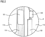
- the circled area A shows the transition area between windshield 112 and right side window 113 (not visible here). Area A is shown in the following figure from the perspective of the driver.
- Fig. 2 shows the monitor 101 and the outside mirror 102 from area A of Fig. 1 from the perspective of the driver in the right part of the interior of the vehicle 103.
- the monitor 101 is mounted on the A-pillar 114 of the driver's cab. Therefore, it does not cover any area of the windshield 112 or the side window 113. Through the side window 113 can be seen the two-part exterior mirror 102 on the right side of the vehicle 103.
- the outside mirror 102 covers part of the field of vision of the driver and is therefore covered by the driver Monitor 101 replaced. It is shown here only for clarity and comparison with the conventional solution.
- Fig. 3 shows the rear part of the trailer 105 with selected lines L1, L2, L3 for determining edge points KP1, KP2, KP3. These can also be further to the left, ie on the trailer, or further to the right, ie in the background.
- motions of individual pixels and an associated image function G (x) as well as their derivative G '(x) are shown.
- the line L1 is arranged in the lower area of the trailer 105, measured approximately at the height of a taillight unit 201 at about 1 m height from the roadway. In any case, the line L1 intersects the edge K5 irrespective of whether the trailer 105 is provided with a structure, container or other load forming the upper part of the rear edge K5 or not.
- edge point K1 The intersection of the line L1 with the edge K5 is the edge point K1.
- a further straight line L3 is located in the upper part of the load or the body and can therefore be evaluated well.
- Their intersection with the edge K5 is the edge point KP3.
- a curved line L2 is shown, with the edge point KP2.
- Their curvature is adapted to properties of the camera 111 and / or the geometry / nature of the trailer 105, but here only indicated schematically.
- the image function is the velocity G (x).
- G (x) In the right part, it is positive, corresponding to the movement of the pixels moving in the camera image 104, KB to the right pixels.
- G (x) In the right-hand area, G (x) is negative, corresponding to the surrounding pixels 109 moving to the left in the camera image KB, 104.
- a derivative is calculated only from an image function based on pixel gray values in the image, but not by a function based on motion vectors , Once the motion vectors are determined, the inventive method is completed.
- Fig. 4 shows on the left, in the middle and on the right each a monitor 101 with different image sections 104a, 104b of the camera image 104.
- the following description refers initially to the left part of Fig. 4 ,
- the image section 104a shown here shows all information relevant to the driver in this situation: the trailer 105 with its rear edge K5 and as object 108 of the environment 109 a following car.
- the edge K5 moves from that in the left part of Fig. 4 starting position corresponding to the motion vector BV from the image section 104a shown on the monitor 101 out into the image section 104b. This is in the middle part of the Fig. 4 shown in which the image section 104a is visible on the monitor 101, and the image section 104b is located to the right of the monitor, so is not visible to the driver.
- the image detail displayed on the monitor 101 is tracked according to the invention according to the value of the movement vector BV.
- the image section 104b is then displayed on the monitor 101, in which the rear edge K5 of the trailer 105 is again visible to the driver. With the edge K5 then the underlying parts of the environment 109 are then visible to the driver.
- the image section 104a which in this situation does not contain information relevant to the driver, is indicated here to the left of the monitor 101, that is to say not visible on the latter.
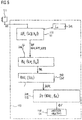
- Fig. 5 shows a control unit 110 according to the invention and a flow chart of the method according to the invention.
- the control unit 110 has an edge point determination unit 215, a motion vector determination unit 216, a reliability measure determination unit 217, a reliability measure evaluation unit 218, and a frame tracking unit 118.
- An output of the camera 111 is is connected to an input of the edge point determination unit 215.
- a first step S1 is executed. Its output is connected to an input of the motion vector determination unit 216.
- the edge point determination unit 215 is also connected to a memory 202.
- one or more lines Li are retrieved from the memory 202, which are used to determine the edge point KPi. It is also possible to store an optionally modified, updated, or new line Li in the memory 202. This is done, for example, from step S1, by loading from outside into the control unit 110, or in another suitable manner.
- the same is also done with the motion vector determination unit 216.
- the motion vectors of the previous image are stored in a memory and used for the initialization of the motion vector determination in the next image.
- the environmental or vehicle model information is then used for initialization in this memory.
- a second step S2 is executed, and its output is connected to the reliability measure determination unit 217.
- this step S31 is executed, its output is connected to the reliability measure unit 218.
- this step S32 is executed, its output is connected to the image detail tracking unit 118.
- a fourth step S4 is executed.
- the position KP, KP1, KP2, KP3, generally referred to as position KPi, of a vertical edge in the image is determined from at least one camera image KB (tj). Also in the feature matching method, the steps as in FIG Fig. 5 shown, all go through. The only difference is that feature points from two consecutive images are used in step S2 to determine the vectors. In the other embodiments, the feature points are determined only from a camera image.
- step S1 At least one line L1, L2, L3, Li intersecting this edge K5 is selected to determine the position of the edge K5 in step S101.
- the edge point KP1, KP2, KP3 is detected in step S102.
- a motion vector BV1, BV2, BV3 is determined from a plurality of temporally consecutive values KPi (Tj)) in the second step S2.
- the line L1, L2, L3, Li is preferably one in an in Fig. 5
- Prescribed fixed line Li stored in memory 202 of the vehicle 103.
- several lines Li are stored in the memory 202 and are adapted to different environmental conditions or vehicle configurations.
- different predetermined lines are provided for different trailer lengths, for different vehicle lengths, for trailers with multiple trailers, for trailers with high or low body, and the like.
- a line Li adapted, for example, to a new configuration of vehicle and trailer is stored in the memory 202 in order to be available in the future. This can be for the short-term next steps, but also for all future implementations of the procedure.
- a reliability measure BVV1, BVV2, BVV3 is determined for the motion vector BV1, BV2, BV3. If the reliability measure BVV1, BVV2, BVV3 is within a predetermined range, in particular if it is greater than a minimum value, a value BV is forwarded to step S4.
- the image section KBA is tracked according to the value of the motion vector BV in the fourth step S4.
- step S1 the line Li is selected in step S121, and in step S122, a plurality of points KPi-k on that line Li.
- step S123 Trailer 105 intersecting line Li each determines a motion vector BVi-k.
- the sequence of motion vectors BVi-k determined for these points KPi-k is then examined for discontinuities along the line Li. For this purpose, the difference ⁇ i-k of two successive motion vectors BVi-k, BVi- (k-1) is formed in step S124, and the maximum of the differences ⁇ i-k is formed in step S125.
- the point PKi at which the maximum lies, that is, the discontinuity occurs, is determined as an edge point PKi.
- the motion vector BVi belonging to this edge point PKi is used according to a variant instead of the motion vector BVi determined in step S2.
- Other known possibilities for determining the edge K5 can also be usefully used here.
- step S1 an image function G (x) along the line Li is evaluated to determine the position of the edge K5, see Fig. 3 , This will be in step S111 a line Li is selected, and in step S112 a derivative G '(x) is determined, ie the gray values along the line Li, and a derivative G' (x) is determined in step S113.
- the selection of the line Li is performed according to a first variant corresponding to the steps S101 or S121.
- step S114 local extrema G (KP1), G (KP1-1) are determined from G '(Li (x)). These correspond to the edge points KPi.
- the derivatives of the image function are taken along the horizontal lines L1, L2, L3. If necessary, these are first low-pass filtered for noise suppression. Derivatives are formed, for example, by finite differences in the intensity function or by color spacings of adjacent pixels in suitable color spaces. Likewise, it is possible to adapt a common method for feature recognition accordingly.
- step S2 A 2x2 equation system is used in step S2, that is to say for the determination of the motion vectors.
- the image intensity derivative vector b is then redetermined and the calculation is iteratively repeated a number of times.
- the details are known by the term "Lucas-Kanade method".
- this adaptation is preferably done as follows: A so-called “scale space” pyramid is calculated only along the horizontal line, that is, in one dimension rather than in two. This creates a two-dimensional scale space in which extremes can be searched by comparing the current value with only eight, rather than else, neighbor values. A subsequent elimination of edge points is not necessary. In this way if there is adequate environmental conditions, it is almost certain that a point will be found on the trailer's edge.
- the motion vector calculation in the second step S2 or in the step 123 takes place as follows:
- a differential optical flow method for example after BD Lucas and T. Kanade (1981) "An iterative image registration technique with an application to stereo vision", Proceedings of Imaging Understanding Workshop, p.121-130 , used.
- Fig. 9 shows a detail for determining the edge point KPi.
- the solution of the equation system does not differ from that known by the term "Lucas-Kanade method".
- the invention differs in this embodiment, as follows: First, the initialization is done with a vector estimate instead of a zero vector in the first interation, which is given by previous motion vectors or by a vehicle model. In some cases, the first resolution hierarchy levels can also be omitted. Second, the regularization perpendicular to the horizontal line. Thirdly, the 2x2 matrices MM or MF are updated instead of a recalculation. This update works as follows: M is an nx2 matrix, where n is the number of pixels used within an environment around the current edge point.
- MM M ⁇ T * M for the calculation of MF is also to be calculated at an adjacent edge position with intersecting environment, then instead of Two matrices MM_1, MM_r and MM_s are calculated, namely the matrix MM_1 from the environmental positions that can only be found in the vicinity of the first edge position KP1, the matrix MM_r from the environmental positions which are to be found exclusively in the vicinity of the second edge position KP2 and the matrix MM_s from the environmental positions which are to be found both in the vicinity of the first edge position KP1 and in the vicinity of the second edge position KP2, that is to say in the intersection.
- MM1 MM_1 + MM_s
- MM_r MM_s
- the method can be extended to more than two surrounding areas.
- MF Red * Reg + MM
- MM M ⁇ T * M
- MF Red * Reg + M ⁇ T * M
- BV MF ⁇ -1 + M ⁇ T * b.
- a 2x2 equation system is solved to update the calculated motion vector.
- L1, L3 it is possible with the aid of a Tikhonov regularizer restricted to the vertical direction to prefer vectors whose vertical component corresponds to that of the vector estimate.
- Curved line L2 is regularized in a correspondingly orthogonal direction by multiplying a rotation matrix.
- the condition number K of the final matrix is preferably used. Double computations at adjacent edge points KPi are avoided by merely updating the matrices instead of recalculating each other in overlapping neighborhoods for matrix determination. Renewed additions in the overlapping area are thus eliminated.
- the motion vector calculation in the second step S2 is carried out as follows: A pixel matching method, so-called block matching, is used. used. Block matching is commonly used in video compression. There are several search patterns for fast search, which typically start at the same place in the previous image KB ( tj-1 ) with the search. In the present case, the search is instead started for acceleration at the estimated position.
- the distance criterion used for example SAD, SSD, is slightly modified by addition of a punishment value. The punishment value corresponds to the distance to the vertical coordinate of the motion vector estimation. As fitting accuracy is typically just this distance criterion used.
- double calculations are preferably also avoided here by reuse of already made additions in the overlapping area.
- the motion vector calculation in the second step S2 is carried out as follows: A method for feature matching is used.
- Fig. 10 shows the display in the monitor 101 with the line L1 actually not shown there, which is here 1m above the ground, the level D1.
- the horizontal line L1 is typically curved in this view, and therefore also shown.
- Full search does not benefit from proper initialization. According to the invention, however, the comparison of feature points between two consecutive camera images KB ( tji ), KB ( tj ) is restricted locally. The search in this case is still limited to the environment of vector estimation. See Fig. 11 with the line L1 (t) at time t and hatches its environment used for vector estimation U (t). The line L1 (t + 1) and its surroundings U (t + 1) at a later time t + 1 is shifted in contrast.
- the detection of edge points KP1, KP2, KP3 in the second image is restricted to the vector line-shifted horizontal line L1 (t + 1) and optionally its environment.
- L1 (t + 1) is a temporarily shifted in the vertical direction Line L1 (t + 1), which, however, is not reused as a line in a later image, on the one hand, and is determined not from the determined motion vectors BVi, but from the vectors of, for example, an environment model.
- the motion vectors BVi represent the movement of the edge points KPi between time t and time t + 1. Accordingly, the method described above can be used here.
- a punishment value is added in the regularization because it is very far away from the shifted horizontal line L1 (t + 1).
- the addition of a punishment value to the feature distance criterion or descriptor value regularizes it.
- the distance between the best matching descriptors in the descriptor space is used in this case as fit.
- a fourth step S4 the camera image section KBA, corresponding to the position KP, KP1, KP2, KP3, tracks the vertical edge K5.
Landscapes
- Engineering & Computer Science (AREA)
- Multimedia (AREA)
- Physics & Mathematics (AREA)
- General Physics & Mathematics (AREA)
- Theoretical Computer Science (AREA)
- Health & Medical Sciences (AREA)
- General Health & Medical Sciences (AREA)
- Vascular Medicine (AREA)
- Mechanical Engineering (AREA)
- Image Analysis (AREA)
- Image Processing (AREA)
Applications Claiming Priority (1)
| Application Number | Priority Date | Filing Date | Title |
|---|---|---|---|
| DE102016216956.4A DE102016216956A1 (de) | 2016-09-07 | 2016-09-07 | Verfahren zur Nachführung eines Bildausschnitts |
Publications (2)
| Publication Number | Publication Date |
|---|---|
| EP3321130A1 true EP3321130A1 (fr) | 2018-05-16 |
| EP3321130B1 EP3321130B1 (fr) | 2019-07-10 |
Family
ID=59761820
Family Applications (1)
| Application Number | Title | Priority Date | Filing Date |
|---|---|---|---|
| EP17188983.5A Active EP3321130B1 (fr) | 2016-09-07 | 2017-09-01 | Procédé de mise à jour d'une section d'image |
Country Status (3)
| Country | Link |
|---|---|
| EP (1) | EP3321130B1 (fr) |
| DE (1) | DE102016216956A1 (fr) |
| ES (1) | ES2746194T3 (fr) |
Cited By (3)
| Publication number | Priority date | Publication date | Assignee | Title |
|---|---|---|---|---|
| WO2023214566A1 (fr) * | 2022-05-06 | 2023-11-09 | 京セラ株式会社 | Dispositif de traitement d'informations |
| EP4553770A1 (fr) * | 2023-11-10 | 2025-05-14 | MEKRA Lang GmbH & Co. KG | Système basé sur une caméra et procédé de détermination de la position d'une remorque |
| US12525022B2 (en) | 2022-09-09 | 2026-01-13 | Stoneridge, Inc. | Camera monitoring system including trailer presence detection using optical flow |
Citations (5)
| Publication number | Priority date | Publication date | Assignee | Title |
|---|---|---|---|---|
| JP2002181518A (ja) * | 2000-10-02 | 2002-06-26 | Isuzu Motors Ltd | トレーラ連結角検出装置 |
| EP1529689A1 (fr) * | 2003-11-05 | 2005-05-11 | DaimlerChrysler AG | Procédé d'affichage du trajectoire d'un essieux tracté de véhicule |
| DE102010032411A1 (de) * | 2010-07-27 | 2012-02-02 | Hans Dominik | Vorrichtung zur Überwachung der seitlichen und rückwärtigen Umgebung eines Fahrzeugs |
| WO2016024405A2 (fr) | 2014-08-12 | 2016-02-18 | Sony Corporation | Dispositif d'affichage de véhicule, procédé de commande d'affichage et système de contrôle à rétroviseur |
| EP3028898A1 (fr) * | 2014-12-05 | 2016-06-08 | MEKRA LANG GmbH & Co. KG | Systeme de vision |
-
2016
- 2016-09-07 DE DE102016216956.4A patent/DE102016216956A1/de not_active Withdrawn
-
2017
- 2017-09-01 ES ES17188983T patent/ES2746194T3/es active Active
- 2017-09-01 EP EP17188983.5A patent/EP3321130B1/fr active Active
Patent Citations (5)
| Publication number | Priority date | Publication date | Assignee | Title |
|---|---|---|---|---|
| JP2002181518A (ja) * | 2000-10-02 | 2002-06-26 | Isuzu Motors Ltd | トレーラ連結角検出装置 |
| EP1529689A1 (fr) * | 2003-11-05 | 2005-05-11 | DaimlerChrysler AG | Procédé d'affichage du trajectoire d'un essieux tracté de véhicule |
| DE102010032411A1 (de) * | 2010-07-27 | 2012-02-02 | Hans Dominik | Vorrichtung zur Überwachung der seitlichen und rückwärtigen Umgebung eines Fahrzeugs |
| WO2016024405A2 (fr) | 2014-08-12 | 2016-02-18 | Sony Corporation | Dispositif d'affichage de véhicule, procédé de commande d'affichage et système de contrôle à rétroviseur |
| EP3028898A1 (fr) * | 2014-12-05 | 2016-06-08 | MEKRA LANG GmbH & Co. KG | Systeme de vision |
Non-Patent Citations (1)
| Title |
|---|
| B.D. LUCAS; T. KANADE: "An iterative image registration technique with an application to stereo vision", PROCEEDINGS OF IMAGING UNDERSTANDING WORKSHOP, 1981, pages 121 - 130 |
Cited By (4)
| Publication number | Priority date | Publication date | Assignee | Title |
|---|---|---|---|---|
| WO2023214566A1 (fr) * | 2022-05-06 | 2023-11-09 | 京セラ株式会社 | Dispositif de traitement d'informations |
| US12525022B2 (en) | 2022-09-09 | 2026-01-13 | Stoneridge, Inc. | Camera monitoring system including trailer presence detection using optical flow |
| EP4553770A1 (fr) * | 2023-11-10 | 2025-05-14 | MEKRA Lang GmbH & Co. KG | Système basé sur une caméra et procédé de détermination de la position d'une remorque |
| JP2025079792A (ja) * | 2023-11-10 | 2025-05-22 | メクラ・ラング・ゲーエムベーハー・ウント・コー・カーゲー | トレーラの位置を決定するためのカメラベースシステムおよび方法 |
Also Published As
| Publication number | Publication date |
|---|---|
| EP3321130B1 (fr) | 2019-07-10 |
| DE102016216956A1 (de) | 2018-03-08 |
| ES2746194T3 (es) | 2020-03-05 |
Similar Documents
| Publication | Publication Date | Title |
|---|---|---|
| EP3413086B1 (fr) | Procédé de caractérisation d'une remorque attachée à un véhicule tracteur, système d'aide à la conduite ainsi qu'ensemble attelé | |
| DE102009005505B4 (de) | Verfahren und Vorrichtung zur Erzeugung eines Abbildes der Umgebung eines Kraftfahrzeugs | |
| DE102017111530A1 (de) | Systeme und Verfahren für ein Zugfahrzeug und einen Anhänger mit Rundumsichtbildgeräten | |
| DE102016003233A1 (de) | Sichtsystem für ein Fahrzeug, insbesondere Nutzfahrzeug | |
| DE102015105248A1 (de) | Erzeugen eines bildes von der umgebung eines gelenkfahrzeugs | |
| DE102016210254A9 (de) | Fahrzeugortung an kreuzungen anhand von visuellen anhaltspunkte, stationären objekten und durch gps | |
| DE102016104730A1 (de) | Verfahren zum Detektieren eines Objekts entlang einer Straße eines Kraftfahrzeugs, Rechenvorrichtung, Fahrerassistenzsystem sowie Kraftfahrzeug | |
| DE112017005447T5 (de) | Objekterfassungsvorrichtung | |
| DE102017112785A1 (de) | Verfahren zum Unterstützen eines Fahrers eines Gespanns beim Manövrieren mit dem Gespann, Totwinkelsystem sowie Gespann | |
| DE102015223176A1 (de) | Verfahren und Vorrichtung zur Ermittlung von Verdeckungsbereichen in der Fahrzeugumgebung eines Fahrzeuges | |
| WO2014094941A1 (fr) | Véhicule automobile pourvu d'un système de surveillance à caméra | |
| DE102017108254B4 (de) | Rundumsichtkamerasystem zur Objekterkennung und -verfolgung und Verfahren zum Ausstatten eines Fahrzeugs mit einem Rundumsichtkamerasystem | |
| DE102015209764A1 (de) | Extrinsische Kalibrierung einer Bilderfassungseinrichtung eines Fahrzeugs | |
| EP3321130B1 (fr) | Procédé de mise à jour d'une section d'image | |
| DE102013012930A1 (de) | Verfahren zum Bestimmen eines aktuellen Abstands und/oder einer aktuellen Geschwindigkeit eines Zielobjekts anhand eines Referenzpunkts in einem Kamerabild, Kamerasystem und Kraftfahrzeug | |
| EP3293971B1 (fr) | Procédé de mise à jour d'une section d'image | |
| DE102010013093A1 (de) | Verfahren und System zur Erstellung eines Modells eines Umfelds eines Fahrzeugs | |
| DE102017219119A1 (de) | Verfahren zur Formerkennung eines Objekts in einem Außenbereich eines Kraftfahrzeugs sowie Kraftfahrzeug | |
| DE102017106152A1 (de) | Ermitteln einer Winkelstellung eines Anhängers mit optimierter Vorlage | |
| DE102017219123A1 (de) | Verfahren zum Ermitteln von Objektgrenzen eines Objekts in einem Außenbereich eines Kraftfahrzeugs sowie Steuervorrichtung und Kraftfahrzeug | |
| DE102014202259B4 (de) | Abschätzung von Parametern eines Nutzfahrzeugs | |
| DE102006037600B4 (de) | Verfahren zur auflösungsabhängigen Darstellung der Umgebung eines Kraftfahrzeugs | |
| DE102019218479A1 (de) | Verfahren und Vorrichtung zur Klassifikation von Objekten auf einer Fahrbahn in einem Umfeld eines Fahrzeugs | |
| DE102023131347A1 (de) | Kamerabasiertes System und Verfahren zum Bestimmen der Position eines Anhängers | |
| DE102020006720A1 (de) | Verfahren zur Lokalisierung einer Silhouette eines Fahrzeuggespanns in von einer Fahrzeugaußenkamera erzeugten Kamerabildern und Fahrzeug |
Legal Events
| Date | Code | Title | Description |
|---|---|---|---|
| PUAI | Public reference made under article 153(3) epc to a published international application that has entered the european phase |
Free format text: ORIGINAL CODE: 0009012 |
|
| STAA | Information on the status of an ep patent application or granted ep patent |
Free format text: STATUS: THE APPLICATION HAS BEEN PUBLISHED |
|
| AK | Designated contracting states |
Kind code of ref document: A1 Designated state(s): AL AT BE BG CH CY CZ DE DK EE ES FI FR GB GR HR HU IE IS IT LI LT LU LV MC MK MT NL NO PL PT RO RS SE SI SK SM TR |
|
| AX | Request for extension of the european patent |
Extension state: BA ME |
|
| STAA | Information on the status of an ep patent application or granted ep patent |
Free format text: STATUS: REQUEST FOR EXAMINATION WAS MADE |
|
| 17P | Request for examination filed |
Effective date: 20181116 |
|
| RBV | Designated contracting states (corrected) |
Designated state(s): AL AT BE BG CH CY CZ DE DK EE ES FI FR GB GR HR HU IE IS IT LI LT LU LV MC MK MT NL NO PL PT RO RS SE SI SK SM TR |
|
| GRAP | Despatch of communication of intention to grant a patent |
Free format text: ORIGINAL CODE: EPIDOSNIGR1 |
|
| STAA | Information on the status of an ep patent application or granted ep patent |
Free format text: STATUS: GRANT OF PATENT IS INTENDED |
|
| INTG | Intention to grant announced |
Effective date: 20190213 |
|
| GRAA | (expected) grant |
Free format text: ORIGINAL CODE: 0009210 |
|
| STAA | Information on the status of an ep patent application or granted ep patent |
Free format text: STATUS: THE PATENT HAS BEEN GRANTED |
|
| AK | Designated contracting states |
Kind code of ref document: B1 Designated state(s): AL AT BE BG CH CY CZ DE DK EE ES FI FR GB GR HR HU IE IS IT LI LT LU LV MC MK MT NL NO PL PT RO RS SE SI SK SM TR |
|
| REG | Reference to a national code |
Ref country code: GB Ref legal event code: FG4D Free format text: NOT ENGLISH |
|
| REG | Reference to a national code |
Ref country code: CH Ref legal event code: EP Ref country code: AT Ref legal event code: REF Ref document number: 1153219 Country of ref document: AT Kind code of ref document: T Effective date: 20190715 |
|
| REG | Reference to a national code |
Ref country code: DE Ref legal event code: R096 Ref document number: 502017001730 Country of ref document: DE |
|
| REG | Reference to a national code |
Ref country code: IE Ref legal event code: FG4D Free format text: LANGUAGE OF EP DOCUMENT: GERMAN |
|
| REG | Reference to a national code |
Ref country code: SE Ref legal event code: TRGR |
|
| REG | Reference to a national code |
Ref country code: NL Ref legal event code: MP Effective date: 20190710 |
|
| REG | Reference to a national code |
Ref country code: LT Ref legal event code: MG4D |
|
| PG25 | Lapsed in a contracting state [announced via postgrant information from national office to epo] |
Ref country code: PT Free format text: LAPSE BECAUSE OF FAILURE TO SUBMIT A TRANSLATION OF THE DESCRIPTION OR TO PAY THE FEE WITHIN THE PRESCRIBED TIME-LIMIT Effective date: 20191111 Ref country code: NL Free format text: LAPSE BECAUSE OF FAILURE TO SUBMIT A TRANSLATION OF THE DESCRIPTION OR TO PAY THE FEE WITHIN THE PRESCRIBED TIME-LIMIT Effective date: 20190710 Ref country code: BG Free format text: LAPSE BECAUSE OF FAILURE TO SUBMIT A TRANSLATION OF THE DESCRIPTION OR TO PAY THE FEE WITHIN THE PRESCRIBED TIME-LIMIT Effective date: 20191010 Ref country code: NO Free format text: LAPSE BECAUSE OF FAILURE TO SUBMIT A TRANSLATION OF THE DESCRIPTION OR TO PAY THE FEE WITHIN THE PRESCRIBED TIME-LIMIT Effective date: 20191010 Ref country code: FI Free format text: LAPSE BECAUSE OF FAILURE TO SUBMIT A TRANSLATION OF THE DESCRIPTION OR TO PAY THE FEE WITHIN THE PRESCRIBED TIME-LIMIT Effective date: 20190710 Ref country code: LT Free format text: LAPSE BECAUSE OF FAILURE TO SUBMIT A TRANSLATION OF THE DESCRIPTION OR TO PAY THE FEE WITHIN THE PRESCRIBED TIME-LIMIT Effective date: 20190710 Ref country code: HR Free format text: LAPSE BECAUSE OF FAILURE TO SUBMIT A TRANSLATION OF THE DESCRIPTION OR TO PAY THE FEE WITHIN THE PRESCRIBED TIME-LIMIT Effective date: 20190710 |
|
| PG25 | Lapsed in a contracting state [announced via postgrant information from national office to epo] |
Ref country code: GR Free format text: LAPSE BECAUSE OF FAILURE TO SUBMIT A TRANSLATION OF THE DESCRIPTION OR TO PAY THE FEE WITHIN THE PRESCRIBED TIME-LIMIT Effective date: 20191011 Ref country code: LV Free format text: LAPSE BECAUSE OF FAILURE TO SUBMIT A TRANSLATION OF THE DESCRIPTION OR TO PAY THE FEE WITHIN THE PRESCRIBED TIME-LIMIT Effective date: 20190710 Ref country code: IS Free format text: LAPSE BECAUSE OF FAILURE TO SUBMIT A TRANSLATION OF THE DESCRIPTION OR TO PAY THE FEE WITHIN THE PRESCRIBED TIME-LIMIT Effective date: 20191110 Ref country code: AL Free format text: LAPSE BECAUSE OF FAILURE TO SUBMIT A TRANSLATION OF THE DESCRIPTION OR TO PAY THE FEE WITHIN THE PRESCRIBED TIME-LIMIT Effective date: 20190710 Ref country code: RS Free format text: LAPSE BECAUSE OF FAILURE TO SUBMIT A TRANSLATION OF THE DESCRIPTION OR TO PAY THE FEE WITHIN THE PRESCRIBED TIME-LIMIT Effective date: 20190710 |
|
| REG | Reference to a national code |
Ref country code: ES Ref legal event code: FG2A Ref document number: 2746194 Country of ref document: ES Kind code of ref document: T3 Effective date: 20200305 |
|
| PG25 | Lapsed in a contracting state [announced via postgrant information from national office to epo] |
Ref country code: TR Free format text: LAPSE BECAUSE OF FAILURE TO SUBMIT A TRANSLATION OF THE DESCRIPTION OR TO PAY THE FEE WITHIN THE PRESCRIBED TIME-LIMIT Effective date: 20190710 |
|
| PG25 | Lapsed in a contracting state [announced via postgrant information from national office to epo] |
Ref country code: DK Free format text: LAPSE BECAUSE OF FAILURE TO SUBMIT A TRANSLATION OF THE DESCRIPTION OR TO PAY THE FEE WITHIN THE PRESCRIBED TIME-LIMIT Effective date: 20190710 Ref country code: PL Free format text: LAPSE BECAUSE OF FAILURE TO SUBMIT A TRANSLATION OF THE DESCRIPTION OR TO PAY THE FEE WITHIN THE PRESCRIBED TIME-LIMIT Effective date: 20190710 Ref country code: EE Free format text: LAPSE BECAUSE OF FAILURE TO SUBMIT A TRANSLATION OF THE DESCRIPTION OR TO PAY THE FEE WITHIN THE PRESCRIBED TIME-LIMIT Effective date: 20190710 Ref country code: RO Free format text: LAPSE BECAUSE OF FAILURE TO SUBMIT A TRANSLATION OF THE DESCRIPTION OR TO PAY THE FEE WITHIN THE PRESCRIBED TIME-LIMIT Effective date: 20190710 |
|
| PG25 | Lapsed in a contracting state [announced via postgrant information from national office to epo] |
Ref country code: CZ Free format text: LAPSE BECAUSE OF FAILURE TO SUBMIT A TRANSLATION OF THE DESCRIPTION OR TO PAY THE FEE WITHIN THE PRESCRIBED TIME-LIMIT Effective date: 20190710 Ref country code: SK Free format text: LAPSE BECAUSE OF FAILURE TO SUBMIT A TRANSLATION OF THE DESCRIPTION OR TO PAY THE FEE WITHIN THE PRESCRIBED TIME-LIMIT Effective date: 20190710 Ref country code: SM Free format text: LAPSE BECAUSE OF FAILURE TO SUBMIT A TRANSLATION OF THE DESCRIPTION OR TO PAY THE FEE WITHIN THE PRESCRIBED TIME-LIMIT Effective date: 20190710 Ref country code: MC Free format text: LAPSE BECAUSE OF FAILURE TO SUBMIT A TRANSLATION OF THE DESCRIPTION OR TO PAY THE FEE WITHIN THE PRESCRIBED TIME-LIMIT Effective date: 20190710 Ref country code: IS Free format text: LAPSE BECAUSE OF FAILURE TO SUBMIT A TRANSLATION OF THE DESCRIPTION OR TO PAY THE FEE WITHIN THE PRESCRIBED TIME-LIMIT Effective date: 20200224 |
|
| REG | Reference to a national code |
Ref country code: DE Ref legal event code: R097 Ref document number: 502017001730 Country of ref document: DE |
|
| PLBE | No opposition filed within time limit |
Free format text: ORIGINAL CODE: 0009261 |
|
| STAA | Information on the status of an ep patent application or granted ep patent |
Free format text: STATUS: NO OPPOSITION FILED WITHIN TIME LIMIT |
|
| PG2D | Information on lapse in contracting state deleted |
Ref country code: IS |
|
| PG25 | Lapsed in a contracting state [announced via postgrant information from national office to epo] |
Ref country code: LU Free format text: LAPSE BECAUSE OF NON-PAYMENT OF DUE FEES Effective date: 20190901 Ref country code: IE Free format text: LAPSE BECAUSE OF NON-PAYMENT OF DUE FEES Effective date: 20190901 |
|
| 26N | No opposition filed |
Effective date: 20200603 |
|
| REG | Reference to a national code |
Ref country code: BE Ref legal event code: MM Effective date: 20190930 |
|
| PG25 | Lapsed in a contracting state [announced via postgrant information from national office to epo] |
Ref country code: SI Free format text: LAPSE BECAUSE OF FAILURE TO SUBMIT A TRANSLATION OF THE DESCRIPTION OR TO PAY THE FEE WITHIN THE PRESCRIBED TIME-LIMIT Effective date: 20190710 Ref country code: BE Free format text: LAPSE BECAUSE OF NON-PAYMENT OF DUE FEES Effective date: 20190930 |
|
| REG | Reference to a national code |
Ref country code: CH Ref legal event code: PL |
|
| PG25 | Lapsed in a contracting state [announced via postgrant information from national office to epo] |
Ref country code: CY Free format text: LAPSE BECAUSE OF FAILURE TO SUBMIT A TRANSLATION OF THE DESCRIPTION OR TO PAY THE FEE WITHIN THE PRESCRIBED TIME-LIMIT Effective date: 20190710 |
|
| PG25 | Lapsed in a contracting state [announced via postgrant information from national office to epo] |
Ref country code: HU Free format text: LAPSE BECAUSE OF FAILURE TO SUBMIT A TRANSLATION OF THE DESCRIPTION OR TO PAY THE FEE WITHIN THE PRESCRIBED TIME-LIMIT; INVALID AB INITIO Effective date: 20170901 Ref country code: MT Free format text: LAPSE BECAUSE OF FAILURE TO SUBMIT A TRANSLATION OF THE DESCRIPTION OR TO PAY THE FEE WITHIN THE PRESCRIBED TIME-LIMIT Effective date: 20190710 |
|
| PG25 | Lapsed in a contracting state [announced via postgrant information from national office to epo] |
Ref country code: LI Free format text: LAPSE BECAUSE OF NON-PAYMENT OF DUE FEES Effective date: 20200930 Ref country code: CH Free format text: LAPSE BECAUSE OF NON-PAYMENT OF DUE FEES Effective date: 20200930 |
|
| GBPC | Gb: european patent ceased through non-payment of renewal fee |
Effective date: 20210901 |
|
| PG25 | Lapsed in a contracting state [announced via postgrant information from national office to epo] |
Ref country code: MK Free format text: LAPSE BECAUSE OF FAILURE TO SUBMIT A TRANSLATION OF THE DESCRIPTION OR TO PAY THE FEE WITHIN THE PRESCRIBED TIME-LIMIT Effective date: 20190710 |
|
| REG | Reference to a national code |
Ref country code: DE Ref legal event code: R081 Ref document number: 502017001730 Country of ref document: DE Owner name: CONTINENTAL AUTOMOTIVE TECHNOLOGIES GMBH, DE Free format text: FORMER OWNER: CONTINENTAL AUTOMOTIVE GMBH, 30165 HANNOVER, DE Ref country code: DE Ref legal event code: R081 Ref document number: 502017001730 Country of ref document: DE Owner name: AUMOVIO GERMANY GMBH, DE Free format text: FORMER OWNER: CONTINENTAL AUTOMOTIVE GMBH, 30165 HANNOVER, DE |
|
| PG25 | Lapsed in a contracting state [announced via postgrant information from national office to epo] |
Ref country code: GB Free format text: LAPSE BECAUSE OF NON-PAYMENT OF DUE FEES Effective date: 20210901 |
|
| P01 | Opt-out of the competence of the unified patent court (upc) registered |
Effective date: 20230522 |
|
| REG | Reference to a national code |
Ref country code: AT Ref legal event code: MM01 Ref document number: 1153219 Country of ref document: AT Kind code of ref document: T Effective date: 20220901 |
|
| PG25 | Lapsed in a contracting state [announced via postgrant information from national office to epo] |
Ref country code: AT Free format text: LAPSE BECAUSE OF NON-PAYMENT OF DUE FEES Effective date: 20220901 |
|
| REG | Reference to a national code |
Ref country code: DE Ref legal event code: R081 Ref document number: 502017001730 Country of ref document: DE Owner name: CONTINENTAL AUTOMOTIVE TECHNOLOGIES GMBH, DE Free format text: FORMER OWNER: CONTINENTAL AUTOMOTIVE TECHNOLOGIES GMBH, 30165 HANNOVER, DE Ref country code: DE Ref legal event code: R081 Ref document number: 502017001730 Country of ref document: DE Owner name: AUMOVIO GERMANY GMBH, DE Free format text: FORMER OWNER: CONTINENTAL AUTOMOTIVE TECHNOLOGIES GMBH, 30165 HANNOVER, DE |
|
| REG | Reference to a national code |
Ref country code: ES Ref legal event code: PC2A Owner name: CONTINENTAL AUTOMOTIVE TECHNOLOGIES GMBH Effective date: 20240410 |
|
| PGFP | Annual fee paid to national office [announced via postgrant information from national office to epo] |
Ref country code: DE Payment date: 20250930 Year of fee payment: 9 |
|
| PGFP | Annual fee paid to national office [announced via postgrant information from national office to epo] |
Ref country code: IT Payment date: 20250923 Year of fee payment: 9 |
|
| PGFP | Annual fee paid to national office [announced via postgrant information from national office to epo] |
Ref country code: FR Payment date: 20250922 Year of fee payment: 9 |
|
| PGFP | Annual fee paid to national office [announced via postgrant information from national office to epo] |
Ref country code: SE Payment date: 20250918 Year of fee payment: 9 |
|
| REG | Reference to a national code |
Ref country code: DE Ref legal event code: R081 Ref document number: 502017001730 Country of ref document: DE Owner name: AUMOVIO GERMANY GMBH, DE Free format text: FORMER OWNER: CONTINENTAL AUTOMOTIVE TECHNOLOGIES GMBH, 30175 HANNOVER, DE |
|
| PGFP | Annual fee paid to national office [announced via postgrant information from national office to epo] |
Ref country code: ES Payment date: 20251028 Year of fee payment: 9 |