EP4553770A1 - Système basé sur une caméra et procédé de détermination de la position d'une remorque - Google Patents
Système basé sur une caméra et procédé de détermination de la position d'une remorque Download PDFInfo
- Publication number
- EP4553770A1 EP4553770A1 EP24208574.4A EP24208574A EP4553770A1 EP 4553770 A1 EP4553770 A1 EP 4553770A1 EP 24208574 A EP24208574 A EP 24208574A EP 4553770 A1 EP4553770 A1 EP 4553770A1
- Authority
- EP
- European Patent Office
- Prior art keywords
- trailer
- feature points
- path
- camera
- image
- Prior art date
- Legal status (The legal status is an assumption and is not a legal conclusion. Google has not performed a legal analysis and makes no representation as to the accuracy of the status listed.)
- Pending
Links
Images






Classifications
-
- B—PERFORMING OPERATIONS; TRANSPORTING
- B60—VEHICLES IN GENERAL
- B60W—CONJOINT CONTROL OF VEHICLE SUB-UNITS OF DIFFERENT TYPE OR DIFFERENT FUNCTION; CONTROL SYSTEMS SPECIALLY ADAPTED FOR HYBRID VEHICLES; ROAD VEHICLE DRIVE CONTROL SYSTEMS FOR PURPOSES NOT RELATED TO THE CONTROL OF A PARTICULAR SUB-UNIT
- B60W40/00—Estimation or calculation of non-directly measurable driving parameters for road vehicle drive control systems not related to the control of a particular sub unit, e.g. by using mathematical models
- B60W40/12—Estimation or calculation of non-directly measurable driving parameters for road vehicle drive control systems not related to the control of a particular sub unit, e.g. by using mathematical models related to parameters of the vehicle itself, e.g. tyre models
-
- G—PHYSICS
- G06—COMPUTING OR CALCULATING; COUNTING
- G06T—IMAGE DATA PROCESSING OR GENERATION, IN GENERAL
- G06T7/00—Image analysis
- G06T7/70—Determining position or orientation of objects or cameras
- G06T7/73—Determining position or orientation of objects or cameras using feature-based methods
-
- G—PHYSICS
- G06—COMPUTING OR CALCULATING; COUNTING
- G06T—IMAGE DATA PROCESSING OR GENERATION, IN GENERAL
- G06T7/00—Image analysis
- G06T7/10—Segmentation; Edge detection
- G06T7/12—Edge-based segmentation
-
- B—PERFORMING OPERATIONS; TRANSPORTING
- B60—VEHICLES IN GENERAL
- B60R—VEHICLES, VEHICLE FITTINGS, OR VEHICLE PARTS, NOT OTHERWISE PROVIDED FOR
- B60R1/00—Optical viewing arrangements; Real-time viewing arrangements for drivers or passengers using optical image capturing systems, e.g. cameras or video systems specially adapted for use in or on vehicles
- B60R1/20—Real-time viewing arrangements for drivers or passengers using optical image capturing systems, e.g. cameras or video systems specially adapted for use in or on vehicles
- B60R1/22—Real-time viewing arrangements for drivers or passengers using optical image capturing systems, e.g. cameras or video systems specially adapted for use in or on vehicles for viewing an area outside the vehicle, e.g. the exterior of the vehicle
- B60R1/23—Real-time viewing arrangements for drivers or passengers using optical image capturing systems, e.g. cameras or video systems specially adapted for use in or on vehicles for viewing an area outside the vehicle, e.g. the exterior of the vehicle with a predetermined field of view
- B60R1/25—Real-time viewing arrangements for drivers or passengers using optical image capturing systems, e.g. cameras or video systems specially adapted for use in or on vehicles for viewing an area outside the vehicle, e.g. the exterior of the vehicle with a predetermined field of view to the sides of the vehicle
-
- B—PERFORMING OPERATIONS; TRANSPORTING
- B60—VEHICLES IN GENERAL
- B60R—VEHICLES, VEHICLE FITTINGS, OR VEHICLE PARTS, NOT OTHERWISE PROVIDED FOR
- B60R1/00—Optical viewing arrangements; Real-time viewing arrangements for drivers or passengers using optical image capturing systems, e.g. cameras or video systems specially adapted for use in or on vehicles
- B60R1/20—Real-time viewing arrangements for drivers or passengers using optical image capturing systems, e.g. cameras or video systems specially adapted for use in or on vehicles
- B60R1/22—Real-time viewing arrangements for drivers or passengers using optical image capturing systems, e.g. cameras or video systems specially adapted for use in or on vehicles for viewing an area outside the vehicle, e.g. the exterior of the vehicle
- B60R1/23—Real-time viewing arrangements for drivers or passengers using optical image capturing systems, e.g. cameras or video systems specially adapted for use in or on vehicles for viewing an area outside the vehicle, e.g. the exterior of the vehicle with a predetermined field of view
- B60R1/26—Real-time viewing arrangements for drivers or passengers using optical image capturing systems, e.g. cameras or video systems specially adapted for use in or on vehicles for viewing an area outside the vehicle, e.g. the exterior of the vehicle with a predetermined field of view to the rear of the vehicle
-
- G—PHYSICS
- G06—COMPUTING OR CALCULATING; COUNTING
- G06T—IMAGE DATA PROCESSING OR GENERATION, IN GENERAL
- G06T7/00—Image analysis
- G06T7/20—Analysis of motion
- G06T7/215—Motion-based segmentation
-
- G—PHYSICS
- G06—COMPUTING OR CALCULATING; COUNTING
- G06T—IMAGE DATA PROCESSING OR GENERATION, IN GENERAL
- G06T7/00—Image analysis
- G06T7/70—Determining position or orientation of objects or cameras
-
- G—PHYSICS
- G06—COMPUTING OR CALCULATING; COUNTING
- G06V—IMAGE OR VIDEO RECOGNITION OR UNDERSTANDING
- G06V10/00—Arrangements for image or video recognition or understanding
- G06V10/40—Extraction of image or video features
- G06V10/44—Local feature extraction by analysis of parts of the pattern, e.g. by detecting edges, contours, loops, corners, strokes or intersections; Connectivity analysis, e.g. of connected components
-
- G—PHYSICS
- G06—COMPUTING OR CALCULATING; COUNTING
- G06V—IMAGE OR VIDEO RECOGNITION OR UNDERSTANDING
- G06V20/00—Scenes; Scene-specific elements
- G06V20/50—Context or environment of the image
- G06V20/56—Context or environment of the image exterior to a vehicle by using sensors mounted on the vehicle
-
- B—PERFORMING OPERATIONS; TRANSPORTING
- B60—VEHICLES IN GENERAL
- B60R—VEHICLES, VEHICLE FITTINGS, OR VEHICLE PARTS, NOT OTHERWISE PROVIDED FOR
- B60R2300/00—Details of viewing arrangements using cameras and displays, specially adapted for use in a vehicle
- B60R2300/30—Details of viewing arrangements using cameras and displays, specially adapted for use in a vehicle characterised by the type of image processing
-
- B—PERFORMING OPERATIONS; TRANSPORTING
- B60—VEHICLES IN GENERAL
- B60R—VEHICLES, VEHICLE FITTINGS, OR VEHICLE PARTS, NOT OTHERWISE PROVIDED FOR
- B60R2300/00—Details of viewing arrangements using cameras and displays, specially adapted for use in a vehicle
- B60R2300/80—Details of viewing arrangements using cameras and displays, specially adapted for use in a vehicle characterised by the intended use of the viewing arrangement
- B60R2300/8046—Details of viewing arrangements using cameras and displays, specially adapted for use in a vehicle characterised by the intended use of the viewing arrangement for replacing a rear-view mirror system
-
- B—PERFORMING OPERATIONS; TRANSPORTING
- B60—VEHICLES IN GENERAL
- B60R—VEHICLES, VEHICLE FITTINGS, OR VEHICLE PARTS, NOT OTHERWISE PROVIDED FOR
- B60R2300/00—Details of viewing arrangements using cameras and displays, specially adapted for use in a vehicle
- B60R2300/80—Details of viewing arrangements using cameras and displays, specially adapted for use in a vehicle characterised by the intended use of the viewing arrangement
- B60R2300/8086—Details of viewing arrangements using cameras and displays, specially adapted for use in a vehicle characterised by the intended use of the viewing arrangement for vehicle path indication
-
- B—PERFORMING OPERATIONS; TRANSPORTING
- B60—VEHICLES IN GENERAL
- B60W—CONJOINT CONTROL OF VEHICLE SUB-UNITS OF DIFFERENT TYPE OR DIFFERENT FUNCTION; CONTROL SYSTEMS SPECIALLY ADAPTED FOR HYBRID VEHICLES; ROAD VEHICLE DRIVE CONTROL SYSTEMS FOR PURPOSES NOT RELATED TO THE CONTROL OF A PARTICULAR SUB-UNIT
- B60W2300/00—Indexing codes relating to the type of vehicle
- B60W2300/14—Tractor-trailers, i.e. combinations of a towing vehicle and one or more towed vehicles, e.g. caravans; Road trains
-
- B—PERFORMING OPERATIONS; TRANSPORTING
- B60—VEHICLES IN GENERAL
- B60W—CONJOINT CONTROL OF VEHICLE SUB-UNITS OF DIFFERENT TYPE OR DIFFERENT FUNCTION; CONTROL SYSTEMS SPECIALLY ADAPTED FOR HYBRID VEHICLES; ROAD VEHICLE DRIVE CONTROL SYSTEMS FOR PURPOSES NOT RELATED TO THE CONTROL OF A PARTICULAR SUB-UNIT
- B60W2420/00—Indexing codes relating to the type of sensors based on the principle of their operation
- B60W2420/40—Photo, light or radio wave sensitive means, e.g. infrared sensors
- B60W2420/403—Image sensing, e.g. optical camera
-
- B—PERFORMING OPERATIONS; TRANSPORTING
- B60—VEHICLES IN GENERAL
- B60W—CONJOINT CONTROL OF VEHICLE SUB-UNITS OF DIFFERENT TYPE OR DIFFERENT FUNCTION; CONTROL SYSTEMS SPECIALLY ADAPTED FOR HYBRID VEHICLES; ROAD VEHICLE DRIVE CONTROL SYSTEMS FOR PURPOSES NOT RELATED TO THE CONTROL OF A PARTICULAR SUB-UNIT
- B60W2520/00—Input parameters relating to overall vehicle dynamics
- B60W2520/22—Articulation angle, e.g. between tractor and trailer
-
- B—PERFORMING OPERATIONS; TRANSPORTING
- B60—VEHICLES IN GENERAL
- B60Y—INDEXING SCHEME RELATING TO ASPECTS CROSS-CUTTING VEHICLE TECHNOLOGY
- B60Y2200/00—Type of vehicle
- B60Y2200/10—Road Vehicles
- B60Y2200/14—Trucks; Load vehicles, Busses
- B60Y2200/147—Trailers, e.g. full trailers or caravans
-
- G—PHYSICS
- G06—COMPUTING OR CALCULATING; COUNTING
- G06T—IMAGE DATA PROCESSING OR GENERATION, IN GENERAL
- G06T2207/00—Indexing scheme for image analysis or image enhancement
- G06T2207/30—Subject of image; Context of image processing
- G06T2207/30248—Vehicle exterior or interior
- G06T2207/30252—Vehicle exterior; Vicinity of vehicle
Definitions
- the invention relates to a camera-based system (vision system or mirror replacement system) and a method for determining the position of one end of a pivotable trailer extending rearward from a vehicle, in particular suitable for a commercial vehicle with a semitrailer, trailer, trailer or other rearwardly extending section pivotable towards the driver's cab or the tractor.
- the driver of a vehicle with a tractor or tractor unit with a rearward-extending pivoting trailer typically monitors the traffic behind them using a side mirror mounted on the side of the tractor unit.
- side mirrors are increasingly being replaced or at least supplemented by camera systems, such as camera monitor systems or mirror replacement systems, which are installed on the side or rear of the vehicle.
- camera systems such as camera monitor systems or mirror replacement systems, which are installed on the side or rear of the vehicle.
- These systems replace or supplement conventional mirror systems required for motor vehicles, such as exterior mirrors (main mirrors), interior mirrors on cars, or wide-angle mirrors and front mirrors on commercial vehicles.
- the driver of the vehicle is shown the corresponding field of vision, which is conventionally made visible through a mirror, sometimes permanently and in real time on a monitor or other display unit, for example in the interior of the vehicle, so that the driver of the vehicle can view the corresponding field of vision at any time, even though he has neither a direct view into the corresponding field of vision nor is a mirror provided.
- a trailer within the meaning of the present teaching includes trailers that are coupled to a vehicle (tractor or tractor unit) by means of a trailer coupling, for example semi-trailers (so-called trailers) that are placed on the rear, lowered area of a tractor and are connected thereto so that they can pivot about at least one vertical axis.
- trailers can also be trailers attached to passenger cars, in which case the passenger car corresponds to the tractor.
- a trailer is a rearwardly extending section that is connected to the rear of the driver's cab of a vehicle.
- Articulated-steer vehicles or articulated trucks are also trailers within the meaning of the invention.
- the object of the invention is to solve the above problem and to detect the position of the trailer end sufficiently accurately for tracking in a monitor image, even for shunting operations when reversing and at low speeds, regardless of the trailer type and information that is recorded, for example, by installed sensors.
- the above object is achieved by a method having the features of claim 1 and by a system having the features of claim 13.
- Advantageous further developments of the invention are specified in the subclaims.
- the method according to the invention for determining the position of a trailer end or a trailer end edge of a pivoting trailer extending rearward from a tractor unit of a vehicle processes chronologically successive camera images acquired by an image sensor of a camera-based system.
- the camera images used for processing do not have to have been acquired directly consecutively; for example, only every second or third camera image can be used for further processing, thereby reducing the volume of image data to be processed.
- the acquired camera images can, for example, be suitably edited, for example with regard to their resolution, contrast and/or color information.
- Raw data of the acquired camera images can be used, or partially edited camera images can be used by the method according to the invention.
- the method according to the invention determines so-called feature points in each of the camera images based on one or more image parameters, at least one calculation variable of one or more image parameters, and/or their gradients, wherein a feature point corresponds to at least one pixel in the camera image.
- a pixel in the camera image can be determined as a feature point if, for example, a value of an image parameter of this pixel differs by a specified amount from a value of a corresponding image parameter of one or more neighboring pixels.
- pixels or pixel clusters can be compared with an adjacent or neighboring pixel cluster with respect to at least one image parameter to determine a feature point.
- the pixels or pixel clusters do not have to be directly adjacent to each other; spatial proximity to one another may be sufficient.
- the method according to the invention selects a plurality of path elements from the determined feature points based on a position shift between the plurality of feature points in a camera image and a corresponding plurality of feature points in a temporally subsequent camera image.
- the path elements are determined, for example, along a predetermined direction that extends along the trailer towards the trailer end and can preferably be determined by the density and/or position of the feature points.
- the predetermined direction can be fixed or, preferably, dynamically adapted during the method. Dynamic adaptation can be based on already defined path elements.
- the method according to the invention then generates at least one so-called path path that describes the trailer course and determines a position on this at least one path path as the position of the trailer end edge.
- the determined path elements or feature points have relevant x, y, dx, dy coordinates, whereby the dx and dy coordinates indicate a position shift in the x and y directions, respectively.
- the above-mentioned selection of the path elements, the weighting of the feature points and/or the weighting of the path elements can be based on a bend angle or information about a relative positional relationship between the tractor unit and the trailer and/or on a vehicle speed.
- a bend angle or a relative positional relationship can be determined independently of the captured camera images, e.g., by means of a bend angle sensor attached to the vehicle, or it can be determined by the data from a Steering angle sensor can be used to estimate the steering angle. Alternatively, it can be estimated using image analysis.
- Other signals about the driving condition recorded by sensors installed in the vehicle can also be considered additionally or alternatively.
- the image parameter is, for example, at least one of a brightness value, color value, gray tone, or gradient of these values.
- this camera image remains unprocessed or is suitably processed to, for example, make a contrast difference, brightness difference, etc. even more clearly visible.
- Other image parameters not explicitly listed here are also conceivable.
- the last-found path element can be used as an initialization point, and further feature points can be selected along the path that lie within a predetermined distance from the path.
- a projection of the last-found feature point onto the path can then indicate the position of the trailer end edge. This allows the actual position of the trailer end to be further approximated.
- Information about the actually determined position of the trailer end can be output, for example, via a CAN and/or Ethernet system or exchanged between software modules.
- the position of the trailer end edge thus determined can be tracked in sequential camera images such that the trailer end appears essentially centrally in each of the sequential camera images.
- additional vehicle characteristics can be taken into account and used to correct the determined position of the trailer's end edge.
- vehicle characteristics can, for example, include geometric features such as length, width, height, etc. and can be stored in advance for a specific type of trailer.
- Other vehicle characteristics such as the position of a rear position light, can be used for the correction.
- This information can be obtained from another method, for example via a CAN or Ethernet system, or provided by additional software modules.
- the determined position of the trailer end edge is verified by generating a block grid with a plurality of rows and columns that define cells on at least part of the camera image.
- the block grid is preferably generated on the image where the position of the trailer end edge has been determined.
- the determined feature points are distributed across the majority of cells of the block grid. Each cell therefore has a number of feature points.
- the distribution of the feature points in the generated block grid is compared according to the invention with distributions of feature points of a plurality of corresponding stored block grids.
- the stored block grids define different distributions of the feature points in connection with an actual trailer end.
- the block grid that best correlates with the generated block grid is selected from the stored block grids.
- a plausibility check can be performed by comparing the determined position of the trailer end with the actual position of the trailer end defined in the selected block grid. If the determined position of the trailer end deviates too significantly from the actual position, the plausibility check can be used to correct the determined position of the trailer end based on this plausibility check, or the trailer end position can be recalculated.
- distributions of the feature points together with the corresponding position of the trailer end can be stored in advance in a block grid, or can be generated and stored in real time at fixed or dynamically adjustable time intervals. Distribution is then compared with such pre-determined distributions and thus the position of the trailer end is verified.
- the different distributions of the feature points with the corresponding trailer ends in the stored block grid depend on the articulation angle between the trailer and the tractor unit.
- Information about the articulation angle can, for example, be stored in conjunction with each block grid.
- the stored block grid for this articulation angle can be directly found and the position of the specific trailer end can be verified.
- Other information indicating the position of the trailer relative to the tractor unit can be used.
- the camera-based system according to the invention includes at least one camera provided on the tractor unit with an image sensor for recording chronologically successive camera images of a lateral area of the trailer, a monitor for displaying a camera image recorded by the camera, and at least one processor configured to carry out the method according to the invention described above.
- the camera-based system according to the invention is a mirror replacement system approved according to UN ECE R46, preferably for commercial vehicles.
- Figure 1 shows a camera-based system according to a preferred embodiment of the invention with display devices 1a, 1b, image recording devices 2a, 2b and processing devices 3a, 3b.
- the image recording devices 2a, 2b are preferably arranged on opposite sides of a vehicle and are connected to the display devices 1a, 1b via the processing devices 3a, 3b.
- the image recording devices 2a, 2b are arranged on the opposite side of the vehicle, as in Figure 2 shown.
- the processing devices 3a, 3b comprise a bend angle determination device (not shown in detail) and an image data processing device and are particularly capable of carrying out the method according to the invention described below for determining the position of a trailer end, tracking the trailer end on the display devices 1a, 1b, and correcting it.
- the display device 1a the image recording devices 2a, and the processing device 3a are described below.
- the explanations apply analogously to the display device 1b, the image recording devices 2b, and the processing device 3b on the opposite side of the vehicle.
- only one processing device can be provided, which assumes the function of the processing devices 3a and 3b.
- the vehicle comprises, for example, a towing vehicle 4 and a trailer 5 pivotably attached to it.
- the image pickup device 2a covers, with its recording area, for example, a field of vision corresponding to a "Primary Mirror (Large) Group II" according to ECE-R46. Other suitable defined fields of vision can be covered by the image pickup device 2a in accordance with national regulations.
- Figure 2a shows the vehicle driving straight ahead without an articulation angle between the towing vehicle 4 and the trailer 5.
- Figure 2b shows a bending angle between the towing vehicle 4 and the trailer 5 and a rear end of the trailer 5 shifts into the field of view of the image recording device 2a with increasing bending angle.
- Figure 3 shows a camera image 6 recorded by the image recording device 2a on a monitor (monitor image), in which the end of the trailer 5 obscures the rear traffic as the articulation angle increases.
- the image recording device 2 is capable of recording a series of sequential images.
- Figure 3 shows a camera-based system from Figure 1 recorded camera image 6 as an image of the trailer 5 with rear traffic 7 displayed on a monitor.
- Figure 4 serves to illustrate the determination of feature points (8) in this camera image 6.
- a plurality of feature points 8 are determined in the two-dimensional camera image 6 with the coordinate axes x and y, as in Figure 4 shown.
- the feature points 8 each correspond to a single pixel or several pixels to a pixel cluster.
- Figure 4 6 illustrates a pixel field 9 in an enlarged view of a partial section of the camera image 6.
- a pixel having neighboring pixels 1 to 5 is determined as a feature point if a predetermined contrast difference exists with at least some of the neighboring pixels.
- Other image parameters for determining whether or not a pixel is a feature point can be used alternatively or cumulatively.
- the Figure 4 certain feature points 8 are weighted in order to emphasize or better determine a contrast difference between neighboring or spatially close pixels.
- a weighting parameter can, for example, be the speed with which feature points change relative to the tractor, i.e., in their position on the image sensor: no or only small changes can be given a higher weighting, since it can be assumed that they are points that move with the vehicle and are therefore, for example, located on the trailer.
- only feature points with or above a certain weighting are then used, so that not all feature points have to be used, which saves computing capacity.
- the Figure 4 shown feature points 8 path elements 10 are selected as with reference to the Figures 5 and 6 described below.
- a starting point 0 is first determined in the camera image 6, as shown in Figure 4 shown.
- the starting point 0 can, but does not have to, be feature point 8.
- the starting point 0 can, for example, be determined based on the articulation angle and the resulting position of the trailer relative to the image acquisition unit.
- Figure 5 As shown, starting from the starting point 0, an image section is defined, which for better illustration is shown in the Figures 5 and 6 represented as a three-dimensional block with a fixed or dynamically adjustable block size (bs). Within this 3D block are a corresponding majority of the feature points 8 of Figure 4 , which are distributed in a three-dimensional space around the starting point 0 as the center of the block of size (bs).
- Each of these feature points is characterized by an x-coordinate (bs x ), a y-coordinate (bs y ), a dx-coordinate (not in Figure 5 shown) and a dy coordinate (bs dy ).
- the dx coordinate and the dy coordinate represent a position shift of a feature point between consecutively recorded camera images.
- path element 10.1 is determined from the "feature point cloud” shown. According to the preferred embodiment of the method according to the invention, this path element corresponds to a center of gravity of the "feature point cloud.” Thus, path element 10.1 can be one of the feature points of the "feature point cloud” or simply be located where most of the feature points are spatially located in the block. Therefore, it does not have to be a feature point (8) itself.
- a new image section or 3D block is defined as a new starting point starting from path element 10.1, which can have the same or a different block size as the initial block, for example, depending on the feature points present in this area.
- the path element 10.2 is determined in a similar manner to path element 10.1.
- the path elements 10 are determined from the feature points along a preferred direction R.
- the preferred direction R is determined by the density and position of the feature points and can either be fixed or adapt dynamically during the process.
- Figure 7 shows, for illustration, the path elements 10 determined according to the preferred embodiment of the method according to the invention superimposed on a camera image 6 together with the feature points 8.
- the path elements 10 extend along the preferred direction R at the lower edge of the trailer 5.
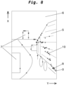
- the path elements 10 can, for example, be as shown in Figure 8 shown, i.e. not along the lower edge of the trailer 5.
- a position of the trailer end or the trailer end edge can be determined, as will be explained further below.
- Figure 9 shows a symbolic representation of the movement of the determined path elements 10 1 to 10 11 or the feature points 8 in the camera image 6 to better illustrate the determination of the path or the trailer end.
- the path elements 10.1 to 10.11 and the feature points 8 of Figure 9 to a coordinate system of Figure 10 projected.
- Figure 10 shows the coordinate axes y, x (out of the plane) and dy.
- a path 11 is generated based on the path elements, which in this preferred embodiment is a straight line.
- the path 11 can also be generated as an n-th degree polynomial; likewise, several different path paths with different degrees of the polynomials can be generated.
- the path elements 10 can be at least partially weighted based on a position or order.
- a metric with weightings of the path elements can be used, wherein the coordinates of the path elements and/or properties of the set of feature points they represent can be used for the weighting, for example, how many feature points, dispersion their coordinate values, dispersion of the "score values", i.e. the properties that make feature points into feature points.
- the path elements 10.1 to 10.9 are all within a predetermined distance from the path 11.
- the determined path elements 10.10 and 10.11, which do not belong to the trailer 5, but to a curb, as in Figure 9 shown are outside the predetermined distance and therefore not on the path 11.
- these path elements 10.10 and 10.11 move faster than the path elements 10.1 to 10.9 when cornering and can therefore be identified as not belonging to the path 11.
- the last path element 10.9 which was taken into account in determining the path 11 and thus identified as sufficiently reliably belonging to the trailer, is used as the initialization point, starting from which further feature points 8 are analyzed with regard to their spatial proximity to the path 11.
- the inventive method is further refined, wherein the coordinate of the last found feature point that lies within the predetermined distance to the path 11 describes the trailer end.
- the end of the trailer can also be calculated from several last found feature points.
- the trailer end is defined as the location on the path at which, viewed in the direction away from the tractor, the image parameter used to select the feature points changes permanently in this direction for the first time (i.e., it does not just reappear after a brief pause along the path).
- the initialization point IP can lie on the path and/or be at least one path element and/or at least one feature point at a given distance from the path. Calculation variables from multiple path elements and/or feature points can be used, for example, mean values, centroids, least square deviations, etc.
- Figure 11 shows, for illustration purposes, a projection of a vertical line 12 at the coordinate a of the last found feature point in the camera image 6 in order to indicate the trailer end determined by the method according to the invention.
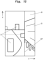
- the position of the trailer end determined in the above manner is further used to track the trailer end when the vehicle is cornering in a monitor image displayed to the driver of the vehicle in such a way that it appears in a preferred position in the monitor image, for example in the middle or plus or minus 0% to 25% shifted from the middle to the left or right in Figure 12 shown in order to reliably keep an eye on the traffic behind you, among other things.
- a block grid 13 is generated on a part of the camera image 6, as shown in Figure 13
- the block grid 13 has, according to the preferred embodiment of the method according to the invention, a fixed shape and a fixed number of rows and columns, which form a plurality of cells 14.
- the number of columns is not equal to the number of rows.
- a grid layout with cells other than rectangular could also be used.
- a distribution of the plurality of feature points 8, which are determined in the above manner, is determined over the plurality of cells 14.
- the Figure 14 The cell 14 shown, for example, has two feature points 8.
- the distribution of the feature points across the cells of the generated block grid 13 determined in this way is then compared with distributions of feature points of a plurality of corresponding stored block grids (not shown).
- the stored block grids each define different distributions of the feature points in connection with a position of the actual trailer end and a kink angle.
- a corresponding saved block grid is selected in which the actual trailer end is defined. By comparing this actual trailer end with the (entered) previously determined trailer end, this can be verified and, if necessary, rejected or corrected.
- the distribution of the feature points and the corresponding trailer ends in the stored block grid can be stored in advance or can be generated and stored in real time when carrying out the method at fixed or dynamically selected time intervals.
- the trailer end can be determined in the above manner by comparing a generated block grid with the stored block grids and used for central tracking in a camera image, as mentioned above, even without the presence of a trailer end to be verified.
- Figure 15 shows a tracked position of the trailer end in a camera image 6 at a preferred position in a displayed monitor image.
- the preferred position is, for example, centered in the monitor image or shifted by, for example, 0% to 25% to the left or right of the center.
- the preferred position can also be offset by, for example, 0% to 25% from the left or right edge of the monitor image.
Landscapes
- Engineering & Computer Science (AREA)
- Multimedia (AREA)
- Physics & Mathematics (AREA)
- General Physics & Mathematics (AREA)
- Theoretical Computer Science (AREA)
- Computer Vision & Pattern Recognition (AREA)
- Mechanical Engineering (AREA)
- Automation & Control Theory (AREA)
- Mathematical Physics (AREA)
- Transportation (AREA)
- Image Analysis (AREA)
- Image Processing (AREA)
Applications Claiming Priority (1)
| Application Number | Priority Date | Filing Date | Title |
|---|---|---|---|
| DE102023131347.9A DE102023131347A1 (de) | 2023-11-10 | 2023-11-10 | Kamerabasiertes System und Verfahren zum Bestimmen der Position eines Anhängers |
Publications (1)
| Publication Number | Publication Date |
|---|---|
| EP4553770A1 true EP4553770A1 (fr) | 2025-05-14 |
Family
ID=93283577
Family Applications (1)
| Application Number | Title | Priority Date | Filing Date |
|---|---|---|---|
| EP24208574.4A Pending EP4553770A1 (fr) | 2023-11-10 | 2024-10-24 | Système basé sur une caméra et procédé de détermination de la position d'une remorque |
Country Status (6)
| Country | Link |
|---|---|
| US (1) | US20250157075A1 (fr) |
| EP (1) | EP4553770A1 (fr) |
| JP (1) | JP7813852B2 (fr) |
| KR (1) | KR20250069425A (fr) |
| CN (1) | CN119991786A (fr) |
| DE (1) | DE102023131347A1 (fr) |
Families Citing this family (1)
| Publication number | Priority date | Publication date | Assignee | Title |
|---|---|---|---|---|
| US20250164636A1 (en) * | 2023-11-17 | 2025-05-22 | Panasonic Automotive Systems Company Of America, Division Of Panasonic Corporation Of North America | Automotive trailer path prediction |
Citations (4)
| Publication number | Priority date | Publication date | Assignee | Title |
|---|---|---|---|---|
| EP3321130A1 (fr) * | 2016-09-07 | 2018-05-16 | Continental Automotive GmbH | Procédé de mise à jour d'une section d'image |
| EP3029929B1 (fr) * | 2014-12-05 | 2019-01-02 | MEKRA LANG GmbH & Co. KG | Systeme de vision |
| DE102018123250A1 (de) * | 2018-09-21 | 2020-03-26 | Connaught Electronics Ltd. | Verfahren und Vorrichtung zum Verfolgen eines Anhängers |
| CN116912797A (zh) * | 2023-07-21 | 2023-10-20 | 雷达新能源汽车(浙江)有限公司 | 拖车角度识别方法、装置、电子设备及可读存储介质 |
Family Cites Families (8)
| Publication number | Priority date | Publication date | Assignee | Title |
|---|---|---|---|---|
| DE10351655A1 (de) * | 2003-11-05 | 2005-06-02 | Daimlerchrysler Ag | Verfahren zur Anzeige des Fahrwegs nachgeschleppter Achsen |
| DE102013214368A1 (de) | 2013-07-23 | 2015-01-29 | Application Solutions (Electronics and Vision) Ltd. | Verfahren und Vorrichtung zur Wiedergabe eines seitlichen und/oder rückwärtigen Umgebungsbereichs eines Fahrzeugs |
| JP6049591B2 (ja) * | 2013-07-31 | 2016-12-21 | 株式会社オハラ | 光学ガラス、プリフォーム材及び光学素子 |
| DE102015014799A1 (de) * | 2015-11-13 | 2017-05-18 | Mekra Lang Gmbh & Co. Kg | System und Verfahren zur Erfassung eines Heckbereiches eines Fahrzeugs |
| DE102016003233A1 (de) * | 2016-03-16 | 2017-09-21 | Mekra Lang Gmbh & Co. Kg | Sichtsystem für ein Fahrzeug, insbesondere Nutzfahrzeug |
| JP7339821B2 (ja) | 2019-09-12 | 2023-09-06 | サカエ理研工業株式会社 | 車両用表示装置 |
| DE102021201525A1 (de) * | 2021-02-17 | 2022-08-18 | Robert Bosch Gesellschaft mit beschränkter Haftung | Verfahren zur Ermittlung einer räumlichen Ausrichtung eines Anhängers |
| EP4435378A4 (fr) | 2021-11-17 | 2026-01-21 | Ihi Corp | Appareil de détection d'angles de liaison pour véhicule combiné, véhicule combiné et procédé de détection d'angle de liaison de véhicule combiné |
-
2023
- 2023-11-10 DE DE102023131347.9A patent/DE102023131347A1/de active Pending
-
2024
- 2024-10-16 JP JP2024181282A patent/JP7813852B2/ja active Active
- 2024-10-23 US US18/924,348 patent/US20250157075A1/en active Pending
- 2024-10-24 EP EP24208574.4A patent/EP4553770A1/fr active Pending
- 2024-10-29 KR KR1020240149133A patent/KR20250069425A/ko active Pending
- 2024-10-31 CN CN202411542968.7A patent/CN119991786A/zh active Pending
Patent Citations (4)
| Publication number | Priority date | Publication date | Assignee | Title |
|---|---|---|---|---|
| EP3029929B1 (fr) * | 2014-12-05 | 2019-01-02 | MEKRA LANG GmbH & Co. KG | Systeme de vision |
| EP3321130A1 (fr) * | 2016-09-07 | 2018-05-16 | Continental Automotive GmbH | Procédé de mise à jour d'une section d'image |
| DE102018123250A1 (de) * | 2018-09-21 | 2020-03-26 | Connaught Electronics Ltd. | Verfahren und Vorrichtung zum Verfolgen eines Anhängers |
| CN116912797A (zh) * | 2023-07-21 | 2023-10-20 | 雷达新能源汽车(浙江)有限公司 | 拖车角度识别方法、装置、电子设备及可读存储介质 |
Also Published As
| Publication number | Publication date |
|---|---|
| JP2025079792A (ja) | 2025-05-22 |
| DE102023131347A1 (de) | 2025-05-15 |
| CN119991786A (zh) | 2025-05-13 |
| US20250157075A1 (en) | 2025-05-15 |
| KR20250069425A (ko) | 2025-05-19 |
| JP7813852B2 (ja) | 2026-02-13 |
Similar Documents
| Publication | Publication Date | Title |
|---|---|---|
| DE102017130566B4 (de) | Sichtsystem zur Erfassung einer Fahrzeugumgebung und Spiegelersatzsystem für ein Fahrzeug mit einem Sichtsystem | |
| EP3219533B1 (fr) | Système de vision pour un véhicule, notamment pour un véhicule utilitaire | |
| EP3024700B1 (fr) | Procédé et dispositif permettant de reproduire une zone latérale et/ou arrière environnant un véhicule | |
| EP3028898B1 (fr) | Systeme de vision | |
| EP3012154B1 (fr) | Procédé et dispositif d'assistance d'un conducteur d'un attelage, notamment d'un attelage de véhicule utilitaire | |
| WO2004109326A1 (fr) | Dispositif et procede pour determiner une orientation dans l'espace d'une semi-remorque ou d'une remorque | |
| DE102009005184A1 (de) | Fahrzeugabtastsystem | |
| DE102021207558B4 (de) | Kamerasystem sowie Verfahren zum Erzeugen einer 3D-Ansicht mit einem Kamerasystem | |
| WO2014094941A1 (fr) | Véhicule automobile pourvu d'un système de surveillance à caméra | |
| DE102017109445A1 (de) | Kalibration einer Fahrzeug-Kameraeinrichtung in Fahrzeuglängsrichtung oder Fahrzeugquerrichtung | |
| DE102016115132A1 (de) | Unterstützung eines Fahrers eines Kraftfahrzeugs mit einem angehängten Anhänger beim Einparken durch virtuelle Sensoren | |
| DE102013103952B4 (de) | Spurerkennung bei voller Fahrt mit einem Rundumsichtsystem | |
| EP3677019B1 (fr) | Procédé et dispositif de commande prévisible d'exposition d'au moins une première caméra de véhicule | |
| DE102022120787A1 (de) | Verfahren zur erkennung und behebung von beeinträchtigungen der bildqualität | |
| DE102011010859B4 (de) | Verfahren zum Betreiben eines Kamerasystems in einem Kraftfahrzeug, Kamerasystem und Kraftfahrzeug | |
| EP2715666A1 (fr) | Procédé de détermination d'un mouvement de tangage d'une caméra montée dans un véhicule et procédé de commande d'une émission lumineuse d'au moins un phare avant d'un véhicule | |
| EP3476696B1 (fr) | Procédé de détermination des limites d'un objet dans une zone externe d'un véhicule automobile ainsi que dispositif de commande et véhicule automobile | |
| EP2131598A2 (fr) | Système de caméra stéréo et procédé de détermination d'au moins une erreur de calibrage d'un système de caméra stéréo | |
| EP4553770A1 (fr) | Système basé sur une caméra et procédé de détermination de la position d'une remorque | |
| DE102013103953B4 (de) | Spurerkennung bei voller Fahrt unter Verwendung mehrerer Kameras | |
| EP2996327B1 (fr) | Systeme de vue environnante pour vehicules dote d'appareils de montage | |
| DE102021116289B4 (de) | Landwirtschaftliches Gerät und Verfahren zur Lenkung des landwirtschaftlichen Geräts | |
| DE102019213746A1 (de) | Verfahren zur Steuerung des Betriebs eines Anbaugerätes | |
| WO2012019931A1 (fr) | Procédé d'affichage d'images sur un dispositif d'affichage embarqué dans un véhicule à moteur, système d'aide à la conduite, et véhicule à moteur | |
| EP4553771A1 (fr) | Système basé sur une caméra et procédé de détermination et de vérification de la position d'une remorque |
Legal Events
| Date | Code | Title | Description |
|---|---|---|---|
| PUAI | Public reference made under article 153(3) epc to a published international application that has entered the european phase |
Free format text: ORIGINAL CODE: 0009012 |
|
| STAA | Information on the status of an ep patent application or granted ep patent |
Free format text: STATUS: REQUEST FOR EXAMINATION WAS MADE |
|
| 17P | Request for examination filed |
Effective date: 20241024 |
|
| AK | Designated contracting states |
Kind code of ref document: A1 Designated state(s): AL AT BE BG CH CY CZ DE DK EE ES FI FR GB GR HR HU IE IS IT LI LT LU LV MC ME MK MT NL NO PL PT RO RS SE SI SK SM TR |
|
| P01 | Opt-out of the competence of the unified patent court (upc) registered |
Free format text: CASE NUMBER: UPC_APP_0330_4553770/2025 Effective date: 20250715 |