EP3321132A1 - Aussenrückspiegelvorrichtung mit beweglicher kopfanordnung - Google Patents
Aussenrückspiegelvorrichtung mit beweglicher kopfanordnung Download PDFInfo
- Publication number
- EP3321132A1 EP3321132A1 EP16198759.9A EP16198759A EP3321132A1 EP 3321132 A1 EP3321132 A1 EP 3321132A1 EP 16198759 A EP16198759 A EP 16198759A EP 3321132 A1 EP3321132 A1 EP 3321132A1
- Authority
- EP
- European Patent Office
- Prior art keywords
- articulation
- assembly
- attachment
- spherical seat
- external rear
- Prior art date
- Legal status (The legal status is an assumption and is not a legal conclusion. Google has not performed a legal analysis and makes no representation as to the accuracy of the status listed.)
- Granted
Links
Images



Classifications
-
- B—PERFORMING OPERATIONS; TRANSPORTING
- B60—VEHICLES IN GENERAL
- B60R—VEHICLES, VEHICLE FITTINGS, OR VEHICLE PARTS, NOT OTHERWISE PROVIDED FOR
- B60R1/00—Optical viewing arrangements; Real-time viewing arrangements for drivers or passengers using optical image capturing systems, e.g. cameras or video systems specially adapted for use in or on vehicles
- B60R1/02—Rear-view mirror arrangements
- B60R1/06—Rear-view mirror arrangements mounted on vehicle exterior
-
- B—PERFORMING OPERATIONS; TRANSPORTING
- B60—VEHICLES IN GENERAL
- B60R—VEHICLES, VEHICLE FITTINGS, OR VEHICLE PARTS, NOT OTHERWISE PROVIDED FOR
- B60R1/00—Optical viewing arrangements; Real-time viewing arrangements for drivers or passengers using optical image capturing systems, e.g. cameras or video systems specially adapted for use in or on vehicles
- B60R1/02—Rear-view mirror arrangements
- B60R1/06—Rear-view mirror arrangements mounted on vehicle exterior
- B60R1/062—Rear-view mirror arrangements mounted on vehicle exterior with remote control for adjusting position
- B60R1/064—Rear-view mirror arrangements mounted on vehicle exterior with remote control for adjusting position by manually powered actuators
- B60R1/066—Rear-view mirror arrangements mounted on vehicle exterior with remote control for adjusting position by manually powered actuators for adjusting the mirror relative to its housing
-
- B—PERFORMING OPERATIONS; TRANSPORTING
- B60—VEHICLES IN GENERAL
- B60R—VEHICLES, VEHICLE FITTINGS, OR VEHICLE PARTS, NOT OTHERWISE PROVIDED FOR
- B60R1/00—Optical viewing arrangements; Real-time viewing arrangements for drivers or passengers using optical image capturing systems, e.g. cameras or video systems specially adapted for use in or on vehicles
- B60R1/02—Rear-view mirror arrangements
- B60R1/06—Rear-view mirror arrangements mounted on vehicle exterior
- B60R1/062—Rear-view mirror arrangements mounted on vehicle exterior with remote control for adjusting position
- B60R1/07—Rear-view mirror arrangements mounted on vehicle exterior with remote control for adjusting position by electrically powered actuators
- B60R1/072—Rear-view mirror arrangements mounted on vehicle exterior with remote control for adjusting position by electrically powered actuators for adjusting the mirror relative to its housing
-
- B—PERFORMING OPERATIONS; TRANSPORTING
- B60—VEHICLES IN GENERAL
- B60R—VEHICLES, VEHICLE FITTINGS, OR VEHICLE PARTS, NOT OTHERWISE PROVIDED FOR
- B60R1/00—Optical viewing arrangements; Real-time viewing arrangements for drivers or passengers using optical image capturing systems, e.g. cameras or video systems specially adapted for use in or on vehicles
- B60R1/20—Real-time viewing arrangements for drivers or passengers using optical image capturing systems, e.g. cameras or video systems specially adapted for use in or on vehicles
- B60R1/22—Real-time viewing arrangements for drivers or passengers using optical image capturing systems, e.g. cameras or video systems specially adapted for use in or on vehicles for viewing an area outside the vehicle, e.g. the exterior of the vehicle
- B60R1/23—Real-time viewing arrangements for drivers or passengers using optical image capturing systems, e.g. cameras or video systems specially adapted for use in or on vehicles for viewing an area outside the vehicle, e.g. the exterior of the vehicle with a predetermined field of view
- B60R1/26—Real-time viewing arrangements for drivers or passengers using optical image capturing systems, e.g. cameras or video systems specially adapted for use in or on vehicles for viewing an area outside the vehicle, e.g. the exterior of the vehicle with a predetermined field of view to the rear of the vehicle
-
- B—PERFORMING OPERATIONS; TRANSPORTING
- B60—VEHICLES IN GENERAL
- B60R—VEHICLES, VEHICLE FITTINGS, OR VEHICLE PARTS, NOT OTHERWISE PROVIDED FOR
- B60R1/00—Optical viewing arrangements; Real-time viewing arrangements for drivers or passengers using optical image capturing systems, e.g. cameras or video systems specially adapted for use in or on vehicles
- B60R1/20—Real-time viewing arrangements for drivers or passengers using optical image capturing systems, e.g. cameras or video systems specially adapted for use in or on vehicles
- B60R1/22—Real-time viewing arrangements for drivers or passengers using optical image capturing systems, e.g. cameras or video systems specially adapted for use in or on vehicles for viewing an area outside the vehicle, e.g. the exterior of the vehicle
- B60R1/28—Real-time viewing arrangements for drivers or passengers using optical image capturing systems, e.g. cameras or video systems specially adapted for use in or on vehicles for viewing an area outside the vehicle, e.g. the exterior of the vehicle with an adjustable field of view
-
- H—ELECTRICITY
- H04—ELECTRIC COMMUNICATION TECHNIQUE
- H04N—PICTORIAL COMMUNICATION, e.g. TELEVISION
- H04N23/00—Cameras or camera modules comprising electronic image sensors; Control thereof
- H04N23/50—Constructional details
- H04N23/51—Housings
-
- H—ELECTRICITY
- H04—ELECTRIC COMMUNICATION TECHNIQUE
- H04N—PICTORIAL COMMUNICATION, e.g. TELEVISION
- H04N7/00—Television systems
- H04N7/18—Closed-circuit television [CCTV] systems, i.e. systems in which the video signal is not broadcast
- H04N7/183—Closed-circuit television [CCTV] systems, i.e. systems in which the video signal is not broadcast for receiving images from a single remote source
-
- B—PERFORMING OPERATIONS; TRANSPORTING
- B60—VEHICLES IN GENERAL
- B60R—VEHICLES, VEHICLE FITTINGS, OR VEHICLE PARTS, NOT OTHERWISE PROVIDED FOR
- B60R1/00—Optical viewing arrangements; Real-time viewing arrangements for drivers or passengers using optical image capturing systems, e.g. cameras or video systems specially adapted for use in or on vehicles
- B60R1/12—Mirror assemblies combined with other articles, e.g. clocks
- B60R2001/1253—Mirror assemblies combined with other articles, e.g. clocks with cameras, video cameras or video screens
Definitions
- the present invention refers to an external rear vision device for a motor vehicle having a fixed base assembly provided for arrangement on the motor vehicle and a moveable head assembly attached to the base assembly via an articulation assembly, said articulation assembly having a fixed part rigidly attached to the fixed base assembly and a moveable part rigidly attached to the moveable head assembly, and said articulation assembly comprising two articulation axes, the direction vectors of said articulation axes being independent of each other.
- EP 2 492 145 B1 refers to an external rear view mirror with a mirror head and a mirror base, which are covered with at least one body element in the form of a body frame, a body cap and a mirror base cover, and a mirror glass that is installed rigidly relative to the mirror head.
- the mirror head rests on the mirror base;
- the body cover of the mirror head is composed of multiple pieces of the body frame and the body cap;
- the mirror base is equipped with a mirror base cover, wherein the body cap has an opening designed for the passage of the mirror base and the mirror base cover.
- the mirror base is rigidly connected to a mirror carrier that carries an electrical glass adjustment drive, wherein the glass adjustment drive is connected to at least one body element.
- Another external rear view mirror assembly for a motor vehicle having a mirror base or foot provided for arrangement on the motor vehicle and a mirror head arranged on the mirror foot as well as a mirror glass accommodated in the mirror head and arranged rigidly and fixed non adjustably with respect thereto, is known from EP 2 492 145 B1 .
- At least one articulation is provided between the mirror head and the arrangement of the mirror foot on the motor vehicle, said articulation comprising a total of two articulation axes, the direction vectors of said articulation axes being independent of each other, and wherein the two articulation axes are associated, jointly and/or independently of each other, to swiveling at least the mirror head from an operating position to a swung-in position and vice versa, to swinging-in at least the mirror head in and against the direction of motion, as well as adjusting an individual adjusting position of at least the mirror glass by adjusting the mirror head depending on, e.g., the seating position and the height of a driver of the motor vehicle, as well as having a first adjusting drive driven by an electric motor and associated to a first articulation axis of the two articulation axes and having a second adjusting drive driven by an electric motor and associated to a second articulation axis of the two articulation axes.
- a foot of the base assembly providing a spherical seat for a casing, in particular a lower casing element, of the head assembly, and frame means providing at least one spherical seat for the casing, with the frame means being rigidly attached to the fixed part or comprised by the fixed part.
- the base assembly can comprise an attachment part for the attachment to the motor vehicle, with the attachment part carrying a control system for or of the articulation assembly, and/or the attachment part guiding cables from the interior of the motor vehicles to the interior of the foot, and/or the attachment part closing the foot at its end opposite its spherical seat.
- the base assembly comprises a carrier part for the attachment of the fixed part of the articulation assembly and/or of a fixation part of the frame means, with the carrier part extending from the spherical seat of the base assembly, and/or the carrier part guiding the cables from inside the foot through a cable exit into the head assembly.
- the carrier part is at least partly arranged within the fixation part, and/or the carrier part is attached to the fixation part by a screw or clip connection and/or by a bayonet attachment.
- the frame means can comprises a support part supporting the fixed part of the articulation assembly, preferably by at least partly encompassing the fixed part, with the support part in particular having a ring shape, and/or by a clips or snap connection.
- the frame means comprises a first spherical seat for the lower casing element and a second spherical seat for an upper casing element of the casing, with preferably the first and second spherical seats of the frame means being provided by extensions arranged at opposite ends of the fixation part and/or on the side of support part facing away from the fixed part of the articulation means.
- the first spherical seat is provided by a first extension facing away from the fixed part of the articulation means and a second extension facing towards the moveable part of the articulation means, with preferably the support part and the first and second extensions form a part of a ring with a cut-out providing a rim facing towards the moveable part of the articulation means.
- the fixation means is provided with a cable exit, with the cable exit of the fixation means being aligned with the cable exit of the carrier part, and/or the cable exit of the fixation means being arranged on the side of the fixation means facing away from the fixed part of the articulation means, and/or cables exiting the cable exit of the fixation means being connected to at least one camera and/or at least one light unit at least partly arranged within the head assembly.
- the lower casing element has a first spherical seat cooperating with the spherical seat of the foot and/or a second spherical seat cooperating with the first spherical seat of the frame means, with preferably the first and second spherical seats of the lower casing element being provided by a base part of the lower casing element.
- the lower casing element preferably has an attachment part fixed to the moveable part of the articulation assembly, with preferably the attachment part extending substantially perpendicularly to the base part of the lower casing element, and/or preferably the attachment part and the frame means being arranged on opposite sides of the unit provided by the fixed and the moveable parts of the articulation means (30), and/or preferably the attachment part encompassing the moveable part at least partly, and/or preferably the attachment part and the moveable part being connected via a clips, plug and/or snap connection.
- the attachment part is provided with a part ring for partly encompassing the moveable part of the articulation assembly, with preferably the part ring is provided by a cut-out determined by the part ring provided by the support part and the first and second extensions.
- the unit can be an actuator for a reflective element, in particular in form of mirror element, being attached to the attachment part.
- the lower casing element carries the upper casing element and/or the camera, and/or a bezel is attached to the lower and upper casing elements, with the bezel preferably surrounding the reflective element.
- a head assembly of an external rear vision device in particular in the form of a mirror head of an external rear view mirror
- an articulation means in particular glass actuator
- spherical seats being provided between parts moving relative to each other such that they can rotate around two articulation axes perpendicular to each other having a common joint point.
- This ensures the maintenance of current end user functionality while offering significant smaller mirror size, with a reduction of size up to 30%.
- the unique layout of the internal mechanism with its spherical seats enhances packaging and performances.
- the articulation assembly is also supported and protected for impact using the spherical seats, in particular due to the arrangement of frame means between the articulation assembly and a casing of the head assembly.
- the casing being assembled from several casing elements, one of which is secured to the moveable part of the articulation assembly, improves the weight distribution and reduces total housing frontal area on the vehicle which in turn improves aero performance and, thus, provides a higher fuel efficiency.
- the pivot system used for the rear vision device of the invention with the single pivot point for two articulation axes permits a mirror adjustment movement while providing dynamic mirror performance and mirror impact support.
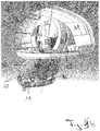
- An external rear vision device of the invention in particular in form of an external rearview mirror, comprises a base assembly 10, a frame means 20, an articulation assembly 30 and a casing 40. These parts will be described in the following with reference to the figures.
- the base assembly 10 comprises a foot 12 provided with a spherical seat 13 from which a shaft type carrier part 14 extends, with the carrier part 14 being provided with a cable exit 15.
- the foot 12 can be closed at its end opposite the spherical seat 13 by an attachment part 11 discussed with respect to figures 5a and 5b below.
- the base assembly 10 is fixedly secured to a motor vehicle (not shown) via the attachment part 11 when in use.
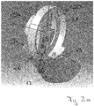
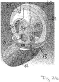
- Figures 2a and 2b depict the frame means 20 fixedly secured to the base assembly 10.
- the frame means 20 is provided by a support part 21 more or less with a ring shape, two spherical seats 22 and 25 provided by extensions 22a, 22b and 25a and a fixation part 23 into which the carrier part 14 of the base assembly 10 is inserted such that the lower spherical seat 22 in figures 2a and 2b is facing the spherical seat 13 of the foot 12.
- the extensions 22a, 22b and 25a extend from opposite sides of the fixation part 23, with two lower extensions 22a, 22b providing a lower spherical seat 22 and the upper spherical seat 25 being provided by an upper extension 25a.
- the fixation part 23 is provided with a cable exit 24 in alignment with the cable exit 15 of the carrier part 14.
- a screw (not shown) can be entered into a screw hole 27 provided by the fixation part 23 and the carrier part 14.
- the articulation means 30 can be attached to the frame means 20 by partly inserting a fixed part 32 of the articulation assembly 30 into the support part 21.
- the respective arrangement can be fixed with a clip connection or the like.
- the fixed part 32 is moveably connected to a moveable part 34 of the articulation assembly 30, with the moveable part 34 facing away from the frame means 20.
- the lower extensions 22a and 22b provide a part ring together with the lower part of support part 21 to provide the spherical seat 22, with a rim 28 being provided by a cut-out at the end facing the moveable part 34 of the articulation assembly 30.
- the moveable part 34 is provided with attachment means 35 in form of recesses for the attachment of a casing 40.
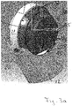
- Figure 3b shows the subassembly of figure 3a with a lower casing element 42 of the casing 40 attached thereto.
- the lower casing element 42 is provided with an attachment part 44 attached to the moveable part 34 of the articulation assembly 30 in a fixed manner in order to move together with the moveable part 34.
- the attachment part 44 is formed with attachment bosses 45 shown in figure 4a , with the attachment bosses 45 being insertable into the attachment recesses 35, and with a part ring 44a for partly encompassing the moveable part 34 to add strength to the connection of the lower casing element 42 and the moveable part 34 due to an enhanced power transmission. Further ribs and the like can be added to further increase the strength.
- the part ring 21, 22a, 22b and the part ring 44a are complementary to each other to lead to a compromise of the spherical seat 22 enabling a smooth movement of the lower casing element 42 together with the moveable part 34 on the one hand and a strong connection of the lower casing element 42 to the moveable part 34 on the other hand.
- the lower casing element 42 is provided with a base part 46 arranged between the foot 12 and the frame means 20, in particular the lower extension of the frame means.
- the base part 46 is provided with a lower spherical seat 47 cooperating with the spherical seat 13 of the foot 12 and an upper spherical seat 48 cooperating with the lowest spherical seat 22 of the frame means 20.
- the overall structure is that of three parts spheres with the inner part sphere provided by the frame means 20 and the outer part sphere provided by the foot 12 of the base assembly 10 being fixed, whereas the part sphere provided by the lower casing element 42, and being arranged in the middle can be moved around two articulation axes in order to provide an inbound/outboard and up/down movement.
- Attached to the attachment part 44 is a not shown mirror glass which can thus be moved via the articulation assembly 30 to fulfil the legal field of view requirements of the rear view mirror.
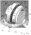
- Figure 4a provides further details of the relative arrangement of the lower casing element 42 with respect to the base assembly 10.
- Figure 4b shows the subassembly of figure 4a together with the fixed part 32 and movable part 34 attached between the carrier part 14 of the base assembly 10 and the attachment part 44 of the lower casing 42.
- the articulation assembly 30 also comprises not shown drive means, in particular comprising two motors for the movement of the moveable part 34 around the two articulation axes, and a control system 36, for the drive means which is partly shown in figures 5a and 5b .
- FIG. 5a not only shows the subassembly provided by the base assembly 10, the articulation assembly 30 and the lower casing element 42, but also an upper casing element 41 of the casing 40 and a camera 50 both being attached to the lower casing element 42.
- Figure 5b shows the subassembly of figure 5a from an opposite side, still without the casing 40 closed via a non-shown additional casing element to complete a head assembly 60.
- figure 5b shows in addition to the upper casing element 41 and the lower casing element 42 a bezel 49 attached to the upper and lower casing elements 41, 42. Said bezel 49 surrounds the not shown mirror glass of the completely assembled external rear view mirror of the present invention.
- control system 36 of the articulation assembly 30 is carried by the attachment part 11.
- the control system 36 is completely arranged within the foot 12.
- cables which exit the base assembly 10 at the cable exit 15 and reach the interior of the head assembly 60 by passing also through to the cable exit 24 of the frame means 20 in order to be connected to the camera 50 and other non-shown units like lighting units and the like, which are arranged within the head assembly 60.
- the head assembly 60 or rather the mirror head as a whole can be articulated using the articulation assembly 30 in particular via the movable part 34.
- the movable part 34 is connected to the drive system which can be a part of the control system 36.
- the control system 36 can also comprise memory means for memorizing a position of the movable 34 and, thus, the mirror glass attached thereto via the attachment part 44.
- the support part 21 is provided in form of an actuator ring which is clipsed onto the fixed part 32 to provide improved support in an impact situation. Due to its upper spherical seat 25 the frame assembly 20 is ensuring a smooth movement of the upper casing element 41 which is also provided with an internal spherical seat, not shown.
- the arrangement of the support part 21 with its extensions 22a, 22b, and 25a providing the spherical seats 22, 25 relative to the movable upper and lower casing elements 41, 42 provide a support and stiffness in all three directions during dynamic and impact situations.
- the result is a smaller mirror system offering the customer a unique external rear view mirror weight as well as aero and vehicle fuel efficiency benefit.
Landscapes
- Engineering & Computer Science (AREA)
- Multimedia (AREA)
- Mechanical Engineering (AREA)
- Signal Processing (AREA)
- Rear-View Mirror Devices That Are Mounted On The Exterior Of The Vehicle (AREA)
Priority Applications (27)
| Application Number | Priority Date | Filing Date | Title |
|---|---|---|---|
| EP16198759.9A EP3321132B1 (de) | 2016-11-14 | 2016-11-14 | Aussenrückspiegelvorrichtung mit beweglicher kopfanordnung |
| US15/603,751 US10759345B2 (en) | 2016-11-14 | 2017-05-24 | External rear view device with moveable head assembly |
| US15/607,894 US10744947B2 (en) | 2012-01-24 | 2017-05-30 | Head section for a rear view device |
| US15/800,413 US20180126910A1 (en) | 2012-01-24 | 2017-11-01 | Rearview device with moveable head assembly |
| JP2017218036A JP6704382B2 (ja) | 2016-11-14 | 2017-11-13 | 移動可能ヘッド組立体を伴う後方視界装置 |
| KR1020170151879A KR102071772B1 (ko) | 2016-11-14 | 2017-11-14 | 가동 헤드 어셈블리를 갖는 리어뷰 디바이스 |
| CN201711120498.5A CN108068700B (zh) | 2016-11-14 | 2017-11-14 | 带有运动头部组件的后视设备 |
| US15/922,366 US10661714B2 (en) | 2012-01-24 | 2018-03-15 | Rearview device with moveable head assembly and method |
| US16/757,834 US11273764B2 (en) | 2012-01-24 | 2018-10-31 | External rearview device, external rearview device kit and vehicle |
| US16/180,857 US11325534B2 (en) | 2013-09-10 | 2018-11-05 | Assembly, method for assembling and disassembling such an assembly, and external rear view device and vehicle with such an assembly |
| US16/569,270 US10766423B2 (en) | 2012-01-24 | 2019-09-12 | Light emitting mirror bezel |
| US16/993,635 US11273766B2 (en) | 2012-01-24 | 2020-08-14 | Light emitting mirror bezel |
| US17/212,121 US12060006B2 (en) | 2012-01-24 | 2021-03-25 | Camera cradle assembly for rear view device |
| US17/401,976 US20210370835A1 (en) | 2012-01-24 | 2021-08-13 | Rearview device with moveable head assembly |
| US17/524,289 US11738687B2 (en) | 2012-09-11 | 2021-11-11 | Assembly, method for assembling and disassembling such an assembly, and external rear view device and vehicle with such an assembly |
| US17/543,866 US11794649B2 (en) | 2012-01-24 | 2021-12-07 | Rearview device with moveable head assembly and method of assembling same |
| US17/587,931 US12134350B2 (en) | 2012-01-24 | 2022-01-28 | Rear view device with actuator and gasket sealing head mover |
| US17/672,436 US11603044B2 (en) | 2012-01-24 | 2022-02-15 | Light emitting mirror bezel |
| US17/680,658 US12122299B2 (en) | 2012-01-24 | 2022-02-25 | External rearview device, external rearview device kit and vehicle |
| US17/939,264 US11890989B2 (en) | 2012-01-24 | 2022-09-07 | External rearview device, external rearview device kit and vehicle |
| US18/832,201 US20250108758A1 (en) | 2012-01-24 | 2023-01-27 | Rear View Device with Actuator and Gasket Sealing Head Mover |
| US18/166,749 US11878629B2 (en) | 2012-01-24 | 2023-02-09 | Light emitting mirror bezel |
| US18/470,495 US12122297B2 (en) | 2016-11-14 | 2023-09-20 | Rearview device with moveable head assembly and method of assembling same |
| US18/485,365 US12090927B2 (en) | 2012-01-24 | 2023-10-12 | Light emitting mirror bezel |
| US18/809,637 US12403832B2 (en) | 2012-01-24 | 2024-08-20 | Light emitting mirror bezel |
| US18/911,553 US20250033562A1 (en) | 2016-11-14 | 2024-10-10 | Rearview device with moveable head assembly and method of assembling same |
| US19/050,451 US20250214508A1 (en) | 2016-11-14 | 2025-02-11 | Rearview device with moveable head assembly and method of assembling same |
Applications Claiming Priority (1)
| Application Number | Priority Date | Filing Date | Title |
|---|---|---|---|
| EP16198759.9A EP3321132B1 (de) | 2016-11-14 | 2016-11-14 | Aussenrückspiegelvorrichtung mit beweglicher kopfanordnung |
Publications (2)
| Publication Number | Publication Date |
|---|---|
| EP3321132A1 true EP3321132A1 (de) | 2018-05-16 |
| EP3321132B1 EP3321132B1 (de) | 2019-01-02 |
Family
ID=57321192
Family Applications (1)
| Application Number | Title | Priority Date | Filing Date |
|---|---|---|---|
| EP16198759.9A Active EP3321132B1 (de) | 2012-01-24 | 2016-11-14 | Aussenrückspiegelvorrichtung mit beweglicher kopfanordnung |
Country Status (2)
| Country | Link |
|---|---|
| US (1) | US10759345B2 (de) |
| EP (1) | EP3321132B1 (de) |
Cited By (11)
| Publication number | Priority date | Publication date | Assignee | Title |
|---|---|---|---|---|
| EP3406488A1 (de) * | 2017-05-24 | 2018-11-28 | SMR Patents S.à.r.l. | Aussenrücksichtvorrichtung mit beweglicher kopfanordnung |
| WO2018215599A1 (en) | 2017-05-24 | 2018-11-29 | Smr Patents Sarl | Pivot joint system and rear view device therewith |
| US10261648B2 (en) | 2009-10-07 | 2019-04-16 | Magna Mirrors Of America, Inc. | Exterior rearview mirror assembly |
| CN110816480A (zh) * | 2018-08-10 | 2020-02-21 | 现代自动车株式会社 | 外部相机镜头清洗系统和清洗方法 |
| US10913395B2 (en) | 2010-02-10 | 2021-02-09 | Magna Mirrors Of America, Inc. | Exterior rearview mirror assembly |
| US11148596B2 (en) | 2017-08-23 | 2021-10-19 | Magna Mirrors Of America, Inc. | Exterior rearview mirror assembly |
| US11325535B2 (en) | 2010-02-10 | 2022-05-10 | Magna Mirrors Of America, Inc. | Exterior rearview mirror assembly |
| US11351919B2 (en) | 2018-05-24 | 2022-06-07 | Magna Mirrors Of America, Inc. | Exterior rearview mirror assembly |
| WO2022200470A1 (en) * | 2021-03-25 | 2022-09-29 | Motherson Innovations Company Ltd. | 3 piece base cover, rear view device, vehicle and assembling and dis-assembling method |
| US11498486B2 (en) | 2009-10-07 | 2022-11-15 | Magna Mirrors Of America, Inc. | Vehicular exterior rearview mirror assembly |
| US12115913B2 (en) | 2010-02-10 | 2024-10-15 | Magna Mirrors Of America, Inc. | Vehicular exterior rearview mirror system |
Families Citing this family (7)
| Publication number | Priority date | Publication date | Assignee | Title |
|---|---|---|---|---|
| US20180126910A1 (en) * | 2012-01-24 | 2018-05-10 | SMR Patents S.à.r.l. | Rearview device with moveable head assembly |
| US11865973B2 (en) * | 2016-09-16 | 2024-01-09 | SMR Patents S.à.r.l. | Housing for a rear view element of a rear view device for a vehicle |
| US11884212B2 (en) * | 2017-06-30 | 2024-01-30 | SMR Patents S.à.r.l. | Rearview device with moveable head assembly and vehicle therewith |
| TWI693826B (zh) * | 2018-11-14 | 2020-05-11 | 明泰科技股份有限公司 | 具有調整環之盲區影像裝置 |
| JP2023524260A (ja) * | 2020-05-07 | 2023-06-09 | マザーソン・イノベーションズ・カンパニー・リミテッド | アクチュエータを備えた後方視界装置、およびそれを備えた車両 |
| DE102021107585B4 (de) * | 2021-03-25 | 2022-11-17 | Motherson Innovations Company Limited | Basisbaugruppe, rückblickvorrichtung und fahrzeug |
| WO2024054810A1 (en) * | 2022-09-09 | 2024-03-14 | Gentex Corporation | Rearview assembly |
Citations (4)
| Publication number | Priority date | Publication date | Assignee | Title |
|---|---|---|---|---|
| FR2605567A1 (fr) * | 1986-10-24 | 1988-04-29 | Mittelhaeuser Bernhard | Retroviseur a rotule pour des vehicules automobiles |
| DE102008026039A1 (de) * | 2008-05-30 | 2009-12-10 | Metallwarenfabrik Wilke Gmbh & Co. Kg | Rückspiegel und Verfahren zum Montieren eines Rückspiegels an einem Kraftwagen |
| EP2492145B1 (de) | 2011-02-23 | 2014-04-02 | SMR Patents S.à.r.l. | Verstellbarer Aussenrückblickspiegel |
| US20150224930A1 (en) * | 2014-02-12 | 2015-08-13 | Magna Mirrors Of America, Inc. | Exterior rearview mirror assembly |
Family Cites Families (8)
| Publication number | Priority date | Publication date | Assignee | Title |
|---|---|---|---|---|
| US2839965A (en) * | 1955-08-30 | 1958-06-24 | Power Brake Parts Mfg Co | Collapsible rear view mirror structure for use with a tractor-trailer combination |
| US4558930A (en) * | 1984-04-04 | 1985-12-17 | Deedrick Harold | Truck mirror adjustable in the horizontal direction |
| US4911545A (en) * | 1988-06-16 | 1990-03-27 | Miller George A | Extendible and pivotable mirrors for vehicles |
| EP2165886B1 (de) * | 2008-09-18 | 2011-01-05 | SMR Patents S.à.r.l. | Rückspiegel |
| DE102009019091B3 (de) * | 2009-04-20 | 2010-10-07 | SMR Patents S.à.r.l. | Spiegelfuß |
| EP2433838B1 (de) * | 2010-09-28 | 2014-04-23 | SMR Patents S.à.r.l. | Außenspiegel |
| DE102012108480B3 (de) * | 2012-09-11 | 2014-02-20 | SMR Patents S.à.r.l. | Kopfteil |
| US10744947B2 (en) * | 2012-01-24 | 2020-08-18 | SMR Patents S.à.r.l. | Head section for a rear view device |
-
2016
- 2016-11-14 EP EP16198759.9A patent/EP3321132B1/de active Active
-
2017
- 2017-05-24 US US15/603,751 patent/US10759345B2/en active Active
Patent Citations (4)
| Publication number | Priority date | Publication date | Assignee | Title |
|---|---|---|---|---|
| FR2605567A1 (fr) * | 1986-10-24 | 1988-04-29 | Mittelhaeuser Bernhard | Retroviseur a rotule pour des vehicules automobiles |
| DE102008026039A1 (de) * | 2008-05-30 | 2009-12-10 | Metallwarenfabrik Wilke Gmbh & Co. Kg | Rückspiegel und Verfahren zum Montieren eines Rückspiegels an einem Kraftwagen |
| EP2492145B1 (de) | 2011-02-23 | 2014-04-02 | SMR Patents S.à.r.l. | Verstellbarer Aussenrückblickspiegel |
| US20150224930A1 (en) * | 2014-02-12 | 2015-08-13 | Magna Mirrors Of America, Inc. | Exterior rearview mirror assembly |
Cited By (23)
| Publication number | Priority date | Publication date | Assignee | Title |
|---|---|---|---|---|
| US11498486B2 (en) | 2009-10-07 | 2022-11-15 | Magna Mirrors Of America, Inc. | Vehicular exterior rearview mirror assembly |
| US12246649B2 (en) | 2009-10-07 | 2025-03-11 | Magna Mirrors Of America, Inc. | Vehicular exterior rearview mirror assembly |
| US10261648B2 (en) | 2009-10-07 | 2019-04-16 | Magna Mirrors Of America, Inc. | Exterior rearview mirror assembly |
| US11970111B2 (en) | 2009-10-07 | 2024-04-30 | Magna Mirrors Of America, Inc. | Vehicular exterior rearview mirror assembly |
| US10906467B2 (en) | 2009-10-07 | 2021-02-02 | Magna Mirrors Of America, Inc. | Exterior rearview mirror assembly |
| US11697373B2 (en) | 2009-10-07 | 2023-07-11 | Magna Mirrors Of America, Inc. | Vehicular exterior rearview mirror assembly |
| US10913395B2 (en) | 2010-02-10 | 2021-02-09 | Magna Mirrors Of America, Inc. | Exterior rearview mirror assembly |
| US11794648B2 (en) | 2010-02-10 | 2023-10-24 | Magna Mirrors Of America, Inc. | Exterior rearview mirror assembly |
| US12115913B2 (en) | 2010-02-10 | 2024-10-15 | Magna Mirrors Of America, Inc. | Vehicular exterior rearview mirror system |
| US11325535B2 (en) | 2010-02-10 | 2022-05-10 | Magna Mirrors Of America, Inc. | Exterior rearview mirror assembly |
| WO2018215599A1 (en) | 2017-05-24 | 2018-11-29 | Smr Patents Sarl | Pivot joint system and rear view device therewith |
| EP3406488A1 (de) * | 2017-05-24 | 2018-11-28 | SMR Patents S.à.r.l. | Aussenrücksichtvorrichtung mit beweglicher kopfanordnung |
| US11148596B2 (en) | 2017-08-23 | 2021-10-19 | Magna Mirrors Of America, Inc. | Exterior rearview mirror assembly |
| US11691567B2 (en) | 2017-08-23 | 2023-07-04 | Magna Mirrors Of America, Inc. | Exterior rearview mirror assembly |
| US12049171B2 (en) | 2017-08-23 | 2024-07-30 | Magna Mirrors Of America, Inc. | Exterior rearview mirror assembly |
| US11623568B2 (en) | 2018-05-24 | 2023-04-11 | Magna Mirrors Of America, Inc. | Exterior rearview mirror assembly |
| US12071074B2 (en) | 2018-05-24 | 2024-08-27 | Magna Mirrors Of America, Inc. | Exterior rearview mirror assembly |
| US11351919B2 (en) | 2018-05-24 | 2022-06-07 | Magna Mirrors Of America, Inc. | Exterior rearview mirror assembly |
| CN110816480A (zh) * | 2018-08-10 | 2020-02-21 | 现代自动车株式会社 | 外部相机镜头清洗系统和清洗方法 |
| CN110816480B (zh) * | 2018-08-10 | 2023-09-19 | 现代自动车株式会社 | 外部相机镜头清洗系统和清洗方法 |
| US12071108B2 (en) | 2018-08-10 | 2024-08-27 | Hyundai Motor Company | Exterior camera lens cleaning system and cleaning method thereof |
| WO2022200470A1 (en) * | 2021-03-25 | 2022-09-29 | Motherson Innovations Company Ltd. | 3 piece base cover, rear view device, vehicle and assembling and dis-assembling method |
| EP4617120A3 (de) * | 2021-03-25 | 2025-12-03 | Motherson Innovations Company Ltd. | 3-teilige basisabdeckung, rückblickvorrichtung, fahrzeug und verfahren zur montage und demontage |
Also Published As
| Publication number | Publication date |
|---|---|
| US10759345B2 (en) | 2020-09-01 |
| EP3321132B1 (de) | 2019-01-02 |
| US20180134218A1 (en) | 2018-05-17 |
Similar Documents
| Publication | Publication Date | Title |
|---|---|---|
| EP3321132A1 (de) | Aussenrückspiegelvorrichtung mit beweglicher kopfanordnung | |
| US5052754A (en) | Headrest arrangement | |
| US6908152B2 (en) | Push lumbar support with flexible pressure surface | |
| EP1923265B1 (de) | Kombinierter Sichtspiegel und Fahrtrichtungsanzeiger für Kraftfahrzeuge | |
| CN106494283B (zh) | 具有娱乐系统的交通工具座椅组件 | |
| US20050161930A1 (en) | Steering column for a motor vehicle | |
| CN104379400A (zh) | 头枕系统和调节头枕的方法 | |
| KR20200058186A (ko) | 자동차용 시트레일 구조 | |
| CN112009333A (zh) | 腰部支撑体总成 | |
| JPH10512211A (ja) | 単一ピボットによる動力折畳式の外部ミラー | |
| CN110316086B (zh) | 车辆、车载显示终端系统及其控制方法 | |
| CN104337100A (zh) | 用于自行车头盔的具有舒适配合件的尺寸调节器 | |
| US6533235B1 (en) | Twisted end interference fit flex shaft | |
| US20040066657A1 (en) | Automotive lamp unit incorporating a pivot element supported on the housing | |
| EP3480062B1 (de) | Rückblickvorrichtung mit beweglicher kopfanordnung | |
| US6962422B1 (en) | Single shell, double view mirror for vehicles | |
| KR20190038691A (ko) | 기어조립체 일체형 엑츄에이터장치 | |
| CN116133900B (zh) | 带有防转动保护的后视镜组件 | |
| CN113183887B (zh) | 一种中控显示屏总成 | |
| JP2008056161A (ja) | 無蓋車両の後方視認装置 | |
| EP3406488B1 (de) | Aussenrücksichtvorrichtung mit beweglicher kopfanordnung | |
| CN118991574A (zh) | 一种电动扶手及座椅 | |
| EP3969328B1 (de) | Rückspiegel für ein fahrzeug | |
| US7287869B2 (en) | Vehicle mirror apparatus | |
| US20020057507A1 (en) | Multi-part drive housing for an actuator for motor vehicle mirrors |
Legal Events
| Date | Code | Title | Description |
|---|---|---|---|
| PUAI | Public reference made under article 153(3) epc to a published international application that has entered the european phase |
Free format text: ORIGINAL CODE: 0009012 |
|
| STAA | Information on the status of an ep patent application or granted ep patent |
Free format text: STATUS: REQUEST FOR EXAMINATION WAS MADE |
|
| 17P | Request for examination filed |
Effective date: 20170831 |
|
| AK | Designated contracting states |
Kind code of ref document: A1 Designated state(s): AL AT BE BG CH CY CZ DE DK EE ES FI FR GB GR HR HU IE IS IT LI LT LU LV MC MK MT NL NO PL PT RO RS SE SI SK SM TR |
|
| AX | Request for extension of the european patent |
Extension state: BA ME |
|
| RAP1 | Party data changed (applicant data changed or rights of an application transferred) |
Owner name: SMR PATENTS S.A.R.L. |
|
| GRAP | Despatch of communication of intention to grant a patent |
Free format text: ORIGINAL CODE: EPIDOSNIGR1 |
|
| STAA | Information on the status of an ep patent application or granted ep patent |
Free format text: STATUS: GRANT OF PATENT IS INTENDED |
|
| INTG | Intention to grant announced |
Effective date: 20180613 |
|
| GRAS | Grant fee paid |
Free format text: ORIGINAL CODE: EPIDOSNIGR3 |
|
| GRAA | (expected) grant |
Free format text: ORIGINAL CODE: 0009210 |
|
| STAA | Information on the status of an ep patent application or granted ep patent |
Free format text: STATUS: THE PATENT HAS BEEN GRANTED |
|
| AK | Designated contracting states |
Kind code of ref document: B1 Designated state(s): AL AT BE BG CH CY CZ DE DK EE ES FI FR GB GR HR HU IE IS IT LI LT LU LV MC MK MT NL NO PL PT RO RS SE SI SK SM TR |
|
| REG | Reference to a national code |
Ref country code: GB Ref legal event code: FG4D |
|
| REG | Reference to a national code |
Ref country code: CH Ref legal event code: EP Ref country code: AT Ref legal event code: REF Ref document number: 1083933 Country of ref document: AT Kind code of ref document: T Effective date: 20190115 |
|
| REG | Reference to a national code |
Ref country code: IE Ref legal event code: FG4D |
|
| REG | Reference to a national code |
Ref country code: DE Ref legal event code: R096 Ref document number: 602016008923 Country of ref document: DE |
|
| REG | Reference to a national code |
Ref country code: NL Ref legal event code: MP Effective date: 20190102 |
|
| REG | Reference to a national code |
Ref country code: LT Ref legal event code: MG4D |
|
| REG | Reference to a national code |
Ref country code: AT Ref legal event code: MK05 Ref document number: 1083933 Country of ref document: AT Kind code of ref document: T Effective date: 20190102 |
|
| PG25 | Lapsed in a contracting state [announced via postgrant information from national office to epo] |
Ref country code: NL Free format text: LAPSE BECAUSE OF FAILURE TO SUBMIT A TRANSLATION OF THE DESCRIPTION OR TO PAY THE FEE WITHIN THE PRESCRIBED TIME-LIMIT Effective date: 20190102 |
|
| PG25 | Lapsed in a contracting state [announced via postgrant information from national office to epo] |
Ref country code: ES Free format text: LAPSE BECAUSE OF FAILURE TO SUBMIT A TRANSLATION OF THE DESCRIPTION OR TO PAY THE FEE WITHIN THE PRESCRIBED TIME-LIMIT Effective date: 20190102 Ref country code: LT Free format text: LAPSE BECAUSE OF FAILURE TO SUBMIT A TRANSLATION OF THE DESCRIPTION OR TO PAY THE FEE WITHIN THE PRESCRIBED TIME-LIMIT Effective date: 20190102 Ref country code: PL Free format text: LAPSE BECAUSE OF FAILURE TO SUBMIT A TRANSLATION OF THE DESCRIPTION OR TO PAY THE FEE WITHIN THE PRESCRIBED TIME-LIMIT Effective date: 20190102 Ref country code: FI Free format text: LAPSE BECAUSE OF FAILURE TO SUBMIT A TRANSLATION OF THE DESCRIPTION OR TO PAY THE FEE WITHIN THE PRESCRIBED TIME-LIMIT Effective date: 20190102 Ref country code: PT Free format text: LAPSE BECAUSE OF FAILURE TO SUBMIT A TRANSLATION OF THE DESCRIPTION OR TO PAY THE FEE WITHIN THE PRESCRIBED TIME-LIMIT Effective date: 20190502 Ref country code: NO Free format text: LAPSE BECAUSE OF FAILURE TO SUBMIT A TRANSLATION OF THE DESCRIPTION OR TO PAY THE FEE WITHIN THE PRESCRIBED TIME-LIMIT Effective date: 20190402 Ref country code: SE Free format text: LAPSE BECAUSE OF FAILURE TO SUBMIT A TRANSLATION OF THE DESCRIPTION OR TO PAY THE FEE WITHIN THE PRESCRIBED TIME-LIMIT Effective date: 20190102 |
|
| PG25 | Lapsed in a contracting state [announced via postgrant information from national office to epo] |
Ref country code: HR Free format text: LAPSE BECAUSE OF FAILURE TO SUBMIT A TRANSLATION OF THE DESCRIPTION OR TO PAY THE FEE WITHIN THE PRESCRIBED TIME-LIMIT Effective date: 20190102 Ref country code: GR Free format text: LAPSE BECAUSE OF FAILURE TO SUBMIT A TRANSLATION OF THE DESCRIPTION OR TO PAY THE FEE WITHIN THE PRESCRIBED TIME-LIMIT Effective date: 20190403 Ref country code: LV Free format text: LAPSE BECAUSE OF FAILURE TO SUBMIT A TRANSLATION OF THE DESCRIPTION OR TO PAY THE FEE WITHIN THE PRESCRIBED TIME-LIMIT Effective date: 20190102 Ref country code: BG Free format text: LAPSE BECAUSE OF FAILURE TO SUBMIT A TRANSLATION OF THE DESCRIPTION OR TO PAY THE FEE WITHIN THE PRESCRIBED TIME-LIMIT Effective date: 20190402 Ref country code: IS Free format text: LAPSE BECAUSE OF FAILURE TO SUBMIT A TRANSLATION OF THE DESCRIPTION OR TO PAY THE FEE WITHIN THE PRESCRIBED TIME-LIMIT Effective date: 20190502 Ref country code: RS Free format text: LAPSE BECAUSE OF FAILURE TO SUBMIT A TRANSLATION OF THE DESCRIPTION OR TO PAY THE FEE WITHIN THE PRESCRIBED TIME-LIMIT Effective date: 20190102 |
|
| REG | Reference to a national code |
Ref country code: DE Ref legal event code: R097 Ref document number: 602016008923 Country of ref document: DE |
|
| PG25 | Lapsed in a contracting state [announced via postgrant information from national office to epo] |
Ref country code: SK Free format text: LAPSE BECAUSE OF FAILURE TO SUBMIT A TRANSLATION OF THE DESCRIPTION OR TO PAY THE FEE WITHIN THE PRESCRIBED TIME-LIMIT Effective date: 20190102 Ref country code: AL Free format text: LAPSE BECAUSE OF FAILURE TO SUBMIT A TRANSLATION OF THE DESCRIPTION OR TO PAY THE FEE WITHIN THE PRESCRIBED TIME-LIMIT Effective date: 20190102 Ref country code: AT Free format text: LAPSE BECAUSE OF FAILURE TO SUBMIT A TRANSLATION OF THE DESCRIPTION OR TO PAY THE FEE WITHIN THE PRESCRIBED TIME-LIMIT Effective date: 20190102 Ref country code: DK Free format text: LAPSE BECAUSE OF FAILURE TO SUBMIT A TRANSLATION OF THE DESCRIPTION OR TO PAY THE FEE WITHIN THE PRESCRIBED TIME-LIMIT Effective date: 20190102 Ref country code: CZ Free format text: LAPSE BECAUSE OF FAILURE TO SUBMIT A TRANSLATION OF THE DESCRIPTION OR TO PAY THE FEE WITHIN THE PRESCRIBED TIME-LIMIT Effective date: 20190102 Ref country code: IT Free format text: LAPSE BECAUSE OF FAILURE TO SUBMIT A TRANSLATION OF THE DESCRIPTION OR TO PAY THE FEE WITHIN THE PRESCRIBED TIME-LIMIT Effective date: 20190102 Ref country code: RO Free format text: LAPSE BECAUSE OF FAILURE TO SUBMIT A TRANSLATION OF THE DESCRIPTION OR TO PAY THE FEE WITHIN THE PRESCRIBED TIME-LIMIT Effective date: 20190102 Ref country code: EE Free format text: LAPSE BECAUSE OF FAILURE TO SUBMIT A TRANSLATION OF THE DESCRIPTION OR TO PAY THE FEE WITHIN THE PRESCRIBED TIME-LIMIT Effective date: 20190102 |
|
| PLBE | No opposition filed within time limit |
Free format text: ORIGINAL CODE: 0009261 |
|
| STAA | Information on the status of an ep patent application or granted ep patent |
Free format text: STATUS: NO OPPOSITION FILED WITHIN TIME LIMIT |
|
| PG25 | Lapsed in a contracting state [announced via postgrant information from national office to epo] |
Ref country code: SM Free format text: LAPSE BECAUSE OF FAILURE TO SUBMIT A TRANSLATION OF THE DESCRIPTION OR TO PAY THE FEE WITHIN THE PRESCRIBED TIME-LIMIT Effective date: 20190102 |
|
| 26N | No opposition filed |
Effective date: 20191003 |
|
| PG25 | Lapsed in a contracting state [announced via postgrant information from national office to epo] |
Ref country code: TR Free format text: LAPSE BECAUSE OF FAILURE TO SUBMIT A TRANSLATION OF THE DESCRIPTION OR TO PAY THE FEE WITHIN THE PRESCRIBED TIME-LIMIT Effective date: 20190102 |
|
| REG | Reference to a national code |
Ref country code: CH Ref legal event code: PL |
|
| PG25 | Lapsed in a contracting state [announced via postgrant information from national office to epo] |
Ref country code: MC Free format text: LAPSE BECAUSE OF FAILURE TO SUBMIT A TRANSLATION OF THE DESCRIPTION OR TO PAY THE FEE WITHIN THE PRESCRIBED TIME-LIMIT Effective date: 20190102 Ref country code: LU Free format text: LAPSE BECAUSE OF NON-PAYMENT OF DUE FEES Effective date: 20191114 Ref country code: CH Free format text: LAPSE BECAUSE OF NON-PAYMENT OF DUE FEES Effective date: 20191130 Ref country code: LI Free format text: LAPSE BECAUSE OF NON-PAYMENT OF DUE FEES Effective date: 20191130 |
|
| REG | Reference to a national code |
Ref country code: BE Ref legal event code: MM Effective date: 20191130 |
|
| REG | Reference to a national code |
Ref country code: DE Ref legal event code: R084 Ref document number: 602016008923 Country of ref document: DE |
|
| PG25 | Lapsed in a contracting state [announced via postgrant information from national office to epo] |
Ref country code: IE Free format text: LAPSE BECAUSE OF NON-PAYMENT OF DUE FEES Effective date: 20191114 |
|
| PG25 | Lapsed in a contracting state [announced via postgrant information from national office to epo] |
Ref country code: BE Free format text: LAPSE BECAUSE OF NON-PAYMENT OF DUE FEES Effective date: 20191130 |
|
| PG25 | Lapsed in a contracting state [announced via postgrant information from national office to epo] |
Ref country code: CY Free format text: LAPSE BECAUSE OF FAILURE TO SUBMIT A TRANSLATION OF THE DESCRIPTION OR TO PAY THE FEE WITHIN THE PRESCRIBED TIME-LIMIT Effective date: 20190102 |
|
| PG25 | Lapsed in a contracting state [announced via postgrant information from national office to epo] |
Ref country code: MT Free format text: LAPSE BECAUSE OF FAILURE TO SUBMIT A TRANSLATION OF THE DESCRIPTION OR TO PAY THE FEE WITHIN THE PRESCRIBED TIME-LIMIT Effective date: 20190102 Ref country code: HU Free format text: LAPSE BECAUSE OF FAILURE TO SUBMIT A TRANSLATION OF THE DESCRIPTION OR TO PAY THE FEE WITHIN THE PRESCRIBED TIME-LIMIT; INVALID AB INITIO Effective date: 20161114 |
|
| PG25 | Lapsed in a contracting state [announced via postgrant information from national office to epo] |
Ref country code: SI Free format text: LAPSE BECAUSE OF FAILURE TO SUBMIT A TRANSLATION OF THE DESCRIPTION OR TO PAY THE FEE WITHIN THE PRESCRIBED TIME-LIMIT Effective date: 20190102 |
|
| PG25 | Lapsed in a contracting state [announced via postgrant information from national office to epo] |
Ref country code: MK Free format text: LAPSE BECAUSE OF FAILURE TO SUBMIT A TRANSLATION OF THE DESCRIPTION OR TO PAY THE FEE WITHIN THE PRESCRIBED TIME-LIMIT Effective date: 20190102 |
|
| P01 | Opt-out of the competence of the unified patent court (upc) registered |
Effective date: 20230616 |
|
| PGFP | Annual fee paid to national office [announced via postgrant information from national office to epo] |
Ref country code: DE Payment date: 20251118 Year of fee payment: 10 |
|
| PGFP | Annual fee paid to national office [announced via postgrant information from national office to epo] |
Ref country code: GB Payment date: 20251120 Year of fee payment: 10 |
|
| PGFP | Annual fee paid to national office [announced via postgrant information from national office to epo] |
Ref country code: FR Payment date: 20251120 Year of fee payment: 10 |