EP3321399A1 - Spinneinheit und spinnmaschine - Google Patents
Spinneinheit und spinnmaschine Download PDFInfo
- Publication number
- EP3321399A1 EP3321399A1 EP17198583.1A EP17198583A EP3321399A1 EP 3321399 A1 EP3321399 A1 EP 3321399A1 EP 17198583 A EP17198583 A EP 17198583A EP 3321399 A1 EP3321399 A1 EP 3321399A1
- Authority
- EP
- European Patent Office
- Prior art keywords
- edge
- main body
- yarn
- body part
- opening
- Prior art date
- Legal status (The legal status is an assumption and is not a legal conclusion. Google has not performed a legal analysis and makes no representation as to the accuracy of the status listed.)
- Granted
Links
- 238000009987 spinning Methods 0.000 title claims abstract description 98
- 230000003746 surface roughness Effects 0.000 claims abstract description 24
- 230000004927 fusion Effects 0.000 claims abstract description 23
- 230000000704 physical effect Effects 0.000 claims description 28
- 239000011347 resin Substances 0.000 claims description 9
- 229920005989 resin Polymers 0.000 claims description 9
- PPBRXRYQALVLMV-UHFFFAOYSA-N Styrene Chemical compound C=CC1=CC=CC=C1 PPBRXRYQALVLMV-UHFFFAOYSA-N 0.000 claims description 6
- 229910052751 metal Inorganic materials 0.000 claims description 6
- 239000002184 metal Substances 0.000 claims description 6
- 239000005011 phenolic resin Substances 0.000 claims description 6
- NLHHRLWOUZZQLW-UHFFFAOYSA-N Acrylonitrile Chemical compound C=CC#N NLHHRLWOUZZQLW-UHFFFAOYSA-N 0.000 claims description 3
- OKTJSMMVPCPJKN-UHFFFAOYSA-N Carbon Chemical compound [C] OKTJSMMVPCPJKN-UHFFFAOYSA-N 0.000 claims description 3
- 229920000122 acrylonitrile butadiene styrene Polymers 0.000 claims description 3
- 239000004676 acrylonitrile butadiene styrene Substances 0.000 claims description 3
- 229910052799 carbon Inorganic materials 0.000 claims description 3
- 238000012986 modification Methods 0.000 claims description 3
- 230000004048 modification Effects 0.000 claims description 3
- XECAHXYUAAWDEL-UHFFFAOYSA-N acrylonitrile butadiene styrene Chemical compound C=CC=C.C=CC#N.C=CC1=CC=CC=C1 XECAHXYUAAWDEL-UHFFFAOYSA-N 0.000 claims description 2
- 239000011248 coating agent Substances 0.000 claims description 2
- 238000000576 coating method Methods 0.000 claims description 2
- 238000012806 monitoring device Methods 0.000 description 10
- 238000011144 upstream manufacturing Methods 0.000 description 7
- 239000002699 waste material Substances 0.000 description 7
- 239000000835 fiber Substances 0.000 description 4
- 238000005304 joining Methods 0.000 description 4
- 230000002093 peripheral effect Effects 0.000 description 4
- 238000012545 processing Methods 0.000 description 4
- 238000004804 winding Methods 0.000 description 4
- 210000000078 claw Anatomy 0.000 description 3
- 230000007547 defect Effects 0.000 description 3
- 230000000694 effects Effects 0.000 description 3
- 238000012360 testing method Methods 0.000 description 3
- 238000004018 waxing Methods 0.000 description 3
- 238000001514 detection method Methods 0.000 description 2
- 238000000465 moulding Methods 0.000 description 2
- 229920001187 thermosetting polymer Polymers 0.000 description 2
- 238000012795 verification Methods 0.000 description 2
- 230000005856 abnormality Effects 0.000 description 1
- 239000000853 adhesive Substances 0.000 description 1
- 230000001070 adhesive effect Effects 0.000 description 1
- 229910052782 aluminium Inorganic materials 0.000 description 1
- XAGFODPZIPBFFR-UHFFFAOYSA-N aluminium Chemical compound [Al] XAGFODPZIPBFFR-UHFFFAOYSA-N 0.000 description 1
- 238000005452 bending Methods 0.000 description 1
- 235000013351 cheese Nutrition 0.000 description 1
- 230000008878 coupling Effects 0.000 description 1
- 238000010168 coupling process Methods 0.000 description 1
- 238000005859 coupling reaction Methods 0.000 description 1
- 229910003460 diamond Inorganic materials 0.000 description 1
- 239000010432 diamond Substances 0.000 description 1
- 238000010438 heat treatment Methods 0.000 description 1
- 238000005259 measurement Methods 0.000 description 1
- 238000000034 method Methods 0.000 description 1
- 238000012544 monitoring process Methods 0.000 description 1
- 230000000149 penetrating effect Effects 0.000 description 1
- 238000003860 storage Methods 0.000 description 1
Images


Classifications
-
- D—TEXTILES; PAPER
- D01—NATURAL OR MAN-MADE THREADS OR FIBRES; SPINNING
- D01H—SPINNING OR TWISTING
- D01H13/00—Other common constructional features, details or accessories
-
- D—TEXTILES; PAPER
- D01—NATURAL OR MAN-MADE THREADS OR FIBRES; SPINNING
- D01H—SPINNING OR TWISTING
- D01H1/00—Spinning or twisting machines in which the product is wound-up continuously
- D01H1/14—Details
- D01H1/16—Framework; Casings; Coverings ; Removal of heat; Means for generating overpressure of air against infiltration of dust; Ducts for electric cables
-
- D—TEXTILES; PAPER
- D01—NATURAL OR MAN-MADE THREADS OR FIBRES; SPINNING
- D01H—SPINNING OR TWISTING
- D01H13/00—Other common constructional features, details or accessories
- D01H13/10—Tension devices
Definitions
- the present invention relates to a spinning unit and a spinning machine.
- a spinning unit including a yarn supplying device adapted to supply a yarn, and a yarn accumulating roller adapted to accumulate the yarn supplied from the yarn supplying device is conventionally known (see e.g., Japanese Unexamined Patent Publication No. 2013-067872 and Japanese Unexamined Patent Publication No. 2013-067891 ) .
- a front panel front cover
- an opening for exposing the yarn accumulating roller to the front surface side (machine outer side) is formed in such front panel.
- a spinning unit of the present invention includes a yarn supplying device adapted to supply a yarn; a yarn accumulating roller adapted to accumulate the yarn supplied from the yarn supplying device; and a front cover arranged outward than the yarn accumulating roller and formed with an opening that exposes the yarn accumulating roller to outside, wherein the front cover includes a main body part and an edge part arranged to form an edge of the opening, and at least a portion of the edge part has a physical property of at least one of hardness higher than hardness of the main body part, a fusion point higher than a fusion point of the main body part, and a surface roughness smaller than a surface roughness of the main body part.
- edge part In removing the yarn entangled around the yarn accumulating roller, the following knowledge is found when the yarn is rubbed against the edge part of the opening in the front cover (hereinafter also simply referred to as "edge part"). That is, the edge part is less likely to be damaged by increasing the hardness of the edge part. By increasing the fusion point of the edge part, the edge part is less likely to be fused by heat generated accompanying the rubbing of the yarn, and the edge part is less likely to be damaged. The edge part is less likely to be damaged by reducing the surface roughness of the edge part.
- At least a portion of the edge part has at least one of the physical properties of hardness higher than the hardness of the main body part, a fusion point higher than the fusion point of the main body part, and a surface roughness smaller than the surface roughness of the main body part. Accordingly, even if the yarn is rubbed against the edge part, the front cover can be prevented from being damaged.
- the at least a portion of the edge part may include at least one of a one-side-edge-part located on one side in a horizontal direction, and an opposite-side-edge-part located on an opposite side in the horizontal direction.
- the yarn is particularly rubbed against the one-side-edge-part on the one side or the opposite-side-edge-part on the opposite side in the horizontal direction in the edge part. The effect of preventing the front cover from being damaged becomes significant when the edge part having the physical property described above includes at least one of the one-side-edge-part and the opposite-side-edge-part.
- the at least a portion of the edge part may include a corner portion or a chamfer portion constituting an edge of a machine outer side of the opening.
- the yarn is sometimes particularly rubbed against the corner portion or the chamfer portion constituting the edge on the machine outer side in the edge part. The effect of preventing the front cover from being damaged becomes significant when the edge part having the physical property described above includes the corner portion or the chamfer portion.
- the at least a portion of the edge part may be formed from an edge member being a different member from the main body part, and the edge member may be fixed to the main body part.
- the configuration in which the edge part has the physical property described above can be easily realized by using the edge member of a different member from the main body part. Furthermore, even if at least a portion of the edge part is damaged, the edge member is merely replaced with a new edge member.
- the spinning unit of the present invention may include a frame to which the front cover is mounted, and the edge member may be sandwiched between the main body part and the frame. According to such configuration, the edge member can be reliably fixed.
- the edge member may extend in an arch shape along the opening when viewed from a machine outer side, and may be fixed to a machine outer side of the main body part by adhesion.
- a configuration in which the edge part has the physical property described above can be easily realized using, for example, the front cover of the existing spinning unit.
- the spinning unit of the present invention may include a sandwiching member fixed to the main body part and arranged to sandwich together with the main body part, at least one of one end part and another end part of the edge member extending in the arch shape. According to such configuration, at least one of the one end part and the other end part of the edge member can be prevented from separating with respect to the main body part.
- the edge member may include a first plate part arranged at a machine outer side of the main body part, and a second plate part arranged vertically on a machine inner side of the first plate part and to constitute an inner wall surface of the opening. According to such configuration, fly waste can be prevented from entering between the main body part and the edge member while preventing the front cover from being damaged.
- the at least a portion of the edge part may be formed integrally with the main body part. According to such configuration, the number of components can be reduced, and the assembly can be facilitated.
- the spinning unit of the present invention includes a yarn hooking member arranged on a downstream side of the yarn accumulating roller, and in a height direction, the at least a portion of the edge part is arranged higher than the yarn hooking member.
- the edge member is formed from phenol resin or metal.
- At least one of a plated layer, a diamond-like carbon coating, and a modification treatment portion is arranged on the at least a portion of the edge part.
- the main body part is formed from acrylonitrile butadiene styrene resin or acrylonitrile ethylene-propylene-diene styrene resin.
- a spinning machine of the present invention includes a plurality of the spinning units.
- the spinning machine also includes the spinning unit, at least a portion of the edge part of the opening in the front cover has at least one of the physical properties of hardness higher than the hardness of the main body part, a fusion point higher than the fusion point of the main body part, and a surface roughness smaller than the surface roughness of the main body part.
- a spinning machine 1 includes a plurality of spinning units 2, a yarn joining cart 3, a doffing cart (not illustrated), a first end frame 4, and a second end frame 5.
- the plurality of the spinning units 2 are arranged in a row.
- Each of the spinning units 2 is adapted to produce a yarn Y and to wind the yarn Y around a package P.
- the yarn joining cart 3 is adapted to perform a yarn joining operation in a spinning unit 2 after the yarn Y is cut, or is broken for some reason in such a spinning unit 2.
- the doffing cart is adapted to doff the package P and to supply a new bobbin B to a spinning unit 2 after the package P is fully-wound in a spinning unit 2.
- a side in which the yarn Y is produced is referred to as “upstream” and a side in which the yarn Y is wound is referred to as “downstream” in a path (i.e., yarn path) on which the yarn Y travels .
- a side in which a pneumatic spinning device 7 is arranged with respect to a frame 14, to be described later, (side in which the yarn path is located with respect to the yarn joining cart 3, side in which an operator's passage is arranged) is referred to as “front side” or “front surface side”, and the opposite side (side in which a sliver case (not illustrated) is disposed) is referred to as "back side".
- An upper side in a vertical direction is simply referred to as “upper side”
- a lower side in the vertical direction is simply referred to as "lower side”.
- the first end frame 4 accommodates, for example, a collecting device adapted to collect a fiber waste, a yarn waste, and the like generated in the spinning units 2.
- the second end frame 5 accommodates an air supplying section adapted to adjust air pressure of compressed air (air) to be supplied to the spinning machine 1 and to supply the air to each section of the spinning machine 1, a drive motor adapted to supply power to each section of the spinning units 2, and the like.
- the second end frame 5 is provided with a machine control device 51, a display screen 52, and an input key 53.
- the machine control device 51 is adapted to intensively manage and control each section of the spinning machine 1.
- the display screen 52 is capable of displaying information relating to set contents and/or a status, or the like of the spinning units 2 . An operator can perform an appropriate operation using the input key 53 to carry out a setting operation of the spinning units 2.
- Each spinning unit 2 includes a draft device (yarn supplying device) 6, the pneumatic spinning device (yarn supplying device) 7, a yarn monitoring device 8, a tension sensor 9, a yarn accumulating device 50, a waxing device 12, and a winding device 13 in this order from upstream in a travelling direction of the yarn Y.
- These devices are directly or indirectly supported by the frame 14 such that the upstream is on an upper side (i.e., downstream is on a lower side).
- the yarn monitoring device 8, the tension sensor 9, and the yarn accumulating device 50 are removably attached to the frame 14 as a yarn processing module 30 (see FIG. 2 ) (details are described later).
- a unit controller 10 is provided for every predetermined number of the spinning units 2 and is adapted to control operations of the spinning units 2.
- the draft device 6 is adapted to draft a sliver (fiber bundle) S.
- the pneumatic spinning device 7 is adapted to produce the yarn Y by twisting a fiber bundle F, which has been drafted by the draft device 6, with whirling airflow.
- the yarn accumulating device 50 is adapted to eliminate a slack of the yarn Y between the pneumatic spinning device 7 and the winding device 13.
- the waxing device 12 is adapted to apply wax to the yarn Y between the yarn accumulating device 50 and the winding device 13 .
- the winding device 13 is adapted to wind the yarn Y around a bobbin B to form a package P.
- the yarn monitoring device 8 is adapted to monitor information on the travelling yarn Y between the pneumatic spinning device 7 and the yarn storage device 11, and to detect presence or absence of a yarn defect based on the information acquired by the monitoring. When detecting the yarn defect, the yarn monitoring device 8 transmits a yarn defect detection signal to the unit controller 10.
- the tension sensor 9 is adapted to measure tension of the travelling yarn Y between the pneumatic spinning device 7 and the yarn accumulating device 50, and to transmit a tension measurement signal to the unit controller 10. When the unit controller 10 determines a presence of an abnormality based on a detection result of the yarn monitoring device 8 and/or the tension sensor 9, the yarn Y is cut in the spinning unit 2.
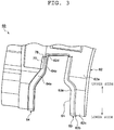
- the yarn processing module 30 includes the yarn accumulating device 50 and a front cover 60.
- the yarn accumulating device 50 includes a yarn accumulating roller 54, and a yarn hooking member 55.
- the yarn accumulating roller 54 has a cylindrical shape around which the yarn Y is wound.
- the shape of the yarn accumulating roller 54 is not limited to the illustrated shape, and may have a multiple-stage tapered shape.
- the yarn accumulating roller 54 winds and accumulates the yarn Y supplied from the pneumatic spinning device 7 around an outer peripheral surface of the yarn accumulating roller 54.
- the yarn accumulating roller 54 is fixed to a drive shaft of an electric motor (drive motor) so as to be rotated by the electric motor.
- the yarn hooking member 55 is a member adapted to hook the yarn Y and wind the yarn Y around the yarn accumulating roller 54 .
- the yarn hooking member 55 is supported in a relatively rotatable manner about a shaft of the yarn accumulating roller 54 at a downstream of the yarn accumulating roller 54.
- the front cover 60 is a panel arranged on a front side (machine outer side) than the yarn accumulating roller 54.
- An opening 61 for exposing the yarn accumulating roller 54 to a front side is formed in the front cover 60 .
- the opening 61 when seen from the front side, the opening 61 is formed in a region that overlaps with a portion or the entire portion of the yarn accumulating roller 54 .
- the opening 61 has an arch shape opened toward the lower side when seen from the front side.
- the opening 61 is configured in the following manner.
- a lateral width (width in a machine left and right direction of the horizontal direction) of a lower side portion and a lateral width of an upper side portion in the opening 61 are constant.
- the lateral width of the lower side portion of the opening 61 is wider than the lateral width of the upper side portion of the opening 61.
- the lateral width smoothly becomes smaller toward the upper side.
- One-side-edge-part located on one side in the horizontal direction hereinafter simply referred to also as "one-side-edge-part" of the edge part of the opening 61 is configured by a first edge member 63, to be described later.
- An opposite-side-edge-part located on the opposite side in the horizontal direction (hereinafter simply referred to also as "opposite-side-edge-part") of the edge part of the opening 61 is configured by a second edge member 64, to be described later. From the lower side toward the upper side, the one-side-edge-part and the opposite-side-edge-part extend straight, and then extend while inclining toward the inner side of the opening 61, and then again extend straight.
- the edge part of the opening 61 is a portion that forms the edge of the opening 61.
- the edge part of the opening 61 is a portion that can be brought into contact with the yarn Y when the yarn Y of the yarn accumulating roller 54 is pulled out toward the front side through the opening 61.
- the edge part of the opening 61 is a portion that at least includes a corner portion constituting the edge on the front side in the opening 61.
- the corner portion is not only a corner portion which apex part has a sharp corner or an obtuse corner, but also includes a corner portion which apex part has a round corner.
- the front cover 60 is removably attached to a unit frame 40, which is a chassis (sheet metal panel) configuring a portion of the frame 14 (see FIG. 1 ), with a screw, and the like.
- An interface 59 including a display section 57 and an operation section 58 is arranged on the front cover 60.
- the display section 57 displays an operation state of the spinning unit 2.
- the operation section 58 is an operation button, and the like operated by an operator to give an operation instruction to the spinning unit 2.
- the yarn processing module 30 further includes a guiding member 37, the yarn monitoring device 8, and the tension sensor 9 arranged in order from the upstream.
- the guiding member 37 is a member adapted to guide the yarn Y to a predetermined position in the yarn monitoring device 8 from the front side.
- the guiding member 37, the yarn monitoring device 8, and the tension sensor 9 are arranged so that the yarn path is located on the front side of the front cover 60.
- the front cover 60 includes a main body part 62, the first edge member 63 , and the second edge member 64 . As illustrated in FIGS. 2 to 6 , the main body part 62 is the main part of the front cover 60.
- the main body part 62 is formed from, for example, acrylonitrile butadiene styrene (ABS) resin or acrylonitrile ethylene-propylene-diene styrene (AES) resin.
- the main body part 62 includes a front wall 62a having a rectangular shape when seen from the front side, an upper wall 62b arranged vertically at an upper end part of a back surface of the front wall 62a, and a lower wall 62c arranged vertically at a lower end part of the back surface of the front wall 62a.
- the opening 61 is formed in the front wall 62a.
- the one side and the opposite side in the horizontal direction of a peripheral region of the opening 61 are formed with a first recess 66 and a second recess 67, respectively.
- a vertical wall 62d is arranged vertically along the edge part.
- the first recess 66 is a recess that engages with the first edge member 63.
- the second recess 67 is a recess that engages with the second edge member 64 .
- the first recess 66 extends along the edge on one side in the horizontal direction of the opening 61.
- the second recess 67 extends along the edge on the opposite side in the horizontal direction of the opening 61. In other words, from the lower side towards the upper side, the first recess 66 and the second recess 67 extend straight, and then extend while inclining toward the inner side of the opening 61, and then again extend straight.
- the first edge member 63 is an edge member configuring one-side-edge-part of the opening 61.
- the first edge member 63 is fixed to the main body part 62 while being engaged with the first recess 66.
- the first edge member 63 is formed from, for example, phenol resin or metal.
- the first edge member 63 includes a front plate part (first plate part) 63a, an end plate part 63b, and a side plate part (second plate part) 63c.
- the front plate part 63a extends in accordance with the shape of the first recess 66.
- the front plate part 63a is fitted into the first recess 66.
- the back surface of the front plate part 63a is brought into contact with the bottom surface of the first recess 66.
- the front plate part 63a is arranged on a front side of the main body part 62.
- the cylindrical boss 72 is arranged vertically on the back surface of the front plate part 63a.
- An upper end projection 73 is arranged at the upper end part of the back surface of the front plate part 63a.
- the upper end projection 73 has a shape that extends toward the upper side while projecting out toward the back side.
- the end plate part 63b is arranged vertically at the lower end part of the back surface of the front plate part 63a.
- the end plate part 63b is brought into contact with the lower wall 62c of the main body part 62.
- the side plate part 63c is arranged vertically along the extending direction of the front plate part 63a. That is, the side plate part 63c is arranged vertically on the machine inner side of the front plate part 63a.
- the side plate part 63c continues to the side of the front plate part 63a so as to be bent at right angle with respect to the front plate part 63a.
- the side plate part 63c is brought into contact with the vertical wall 62d of the main body part 62.
- the side plate part 63c constitutes an inner wall surface of the opening 61.
- the front plate part 63a is fitted into the first recess 66, the end plate part 63b is brought into contact with the lower wall 62c, and the side plate part 63c is brought into contact with the vertical wall 62d.
- the upper end projection 73 is inserted into the opening 70 of the first recess 66 so as to enter the back surface of the front wall 62a (see FIG. 4 ).
- the boss 72 is inserted into the through hole 68 of the first recess 66.
- the first edge member 63 is removably fixed to the main body part 62 by tightening a screw N (see FIG. 4 ) to the boss 72 in such a state.
- Such first edge member 63 includes a corner portion constituting the edge on the front side in the one-side-edge-part of the opening 61.
- the second edge member 64 is an edge member that configures the opposite-side-edge-part of the opening 61.
- the second edge member 64 is fixed to the main body part 62 while being engaged with the second recess 67.
- the second edge member 64 is formed from, for example, phenol resin or metal.
- the second edge member 64 includes a front plate part (first plate part) 64a, an end plate part 64b, and a side plate part (second plate part) 64c.
- the front plate part 64a extends in accordance with the shape of the second recess 67.
- the front plate part 64a is fitted into the second recess 67.
- the back surface of the front plate part 64a is brought into contact with the bottom surface of the second recess 67.
- the front plate part 64a is arranged on a front side of the main body part 62 .
- the cylindrical boss 75 is arranged vertically on the back surface of the front plate part 64a.
- An upper end piece 77 is arranged at the upper end part of the front plate part 64a via a step 76.
- the upper end piece 77 is located on the back side than the front plate part 64a, and arranged to extend toward the upper side.
- a distal end portion of the upper end piece 77 includes a bent end portion 78 bent so as to deflect toward the back side (arranged in a bent manner to project out toward the back side).
- the end plate part 64b is arranged vertically at the lower end part of the back surface of the front plate part 64a.
- the end plate part 64b is brought into contact with the lower wall 62c of the main body part 62.
- the side plate part 64c is arranged vertically along the front plate part 64a. That is, the side plate part 64c is arranged vertically on the machine inner side of the front plate part 64a.
- the side plate part 64c continues to the side of the front plate part 64a so as to be bent at right angle with respect to the front plate part 64a.
- the side plate part 64c is brought into contact with the vertical wall 62d of the main body part 62 .
- the side plate part 64c constitutes an inner wall surface of the opening 61.
- the front plate part 64a is fitted into the second recess 67, the end plate part 64b is brought into contact with the lower wall 62c, and the side plate part 64c is brought into contact with the vertical wall 62d.
- the upper end piece 77 is inserted into the opening 71 of the second recess 67, and the bent end portion 78 is inserted into the opening 71 so as to enter the back surface of the front wall 62a (see FIG. 4 ) .
- the boss 75 is inserted into the through hole 69 of the second recess 67 .
- the second edge member 64 is removably fixed to the main body part 62 by tightening a screw N (see FIG. 4 ) to the boss 75 in such a state.
- Such second edge member 64 includes a corner portion constituting the edge on the front side in the opposite-side-edge-part of the opening 61.
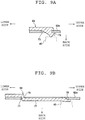
- FIGS. 9A and 9B are cross-sectional views of a cross-section parallel to an upper-lower direction and a front-back direction.
- the first edge member 63 and the second edge member 64 have a hardness higher than a hardness of the main body part 62, a fusion point higher than a fusion point of the main body part 62, and a surface roughness smaller than a surface roughness of the main body part 62 .
- the first edge member 63 and the second edge member 64 have a physical property of having a hardness higher than a hardness of the main body part 62, a physical property of having fusion point higher than a fusion point of the main body part 62, and a physical property of having a surface roughness smaller than a surface roughness of the main body part 62 (such physical properties are also hereinafter collectively referred to as "each physical property").
- the Rockwell hardness is between R85 and R105
- the fusion point is between 100°C and 110°C (heatproof temperature is between 60°C and 95°C, heat distortion temperature is between 96°C and 105°C)
- a surface roughness Ra is 4.
- the Rockwell hardness is between M100 and M120
- the surface roughness Ra is smaller than or equal to 1.6.
- the phenol resin is a thermosetting resin, which heatproof temperature is between 150°C and 180°C, and the heat distortion temperature is between 150°C and 175°C.
- the operator pulls out the yarn Y toward the front side through the opening 61 of the front cover 60 to remove the entangled yarn Y.
- the yarn Y may rub against the one-side-edge-part and the opposite-side-edge-part of the opening 61.
- the following effects are obtained as the first edge member 63 and the second edge member 64 configuring the one-side-edge-part and the opposite-side-edge-part have each physical property described above.
- the hardness of the one-side-edge-part and the opposite-side-edge-part can be made higher than the main body part 62, so that the one-side-edge-part and the opposite-side-edge-part are less likely to be damaged.
- the fusion point of the one-side-edge-part and the opposite-side-edge-part can be made higher than the main body part 62, so that the one-side-edge-part and the opposite-side-edge-part are less likely to be fused by heat generated accompanying the rubbing of the yarn Y, and the one-side-edge-part and the opposite-side-edge-part are less likely to be damaged.
- the surface roughness of the one-side-edge-part and the opposite-side-edge-part can be made smaller than the main body part 62, so that the one-side-edge-part and the opposite-side-edge-part are less likely to be damaged.
- the one-side-edge-part and the opposite-side-edge-part can be prevented from being damaged and furthermore, the front cover 60 can be prevented from being damaged.
- the yarn Y In removing the yarn Y entangled around the yarn accumulating roller 54, the yarn Y particularly tends to be rubbed against the one-side-edge-part and the opposite-side-edge-part in the edge part of the opening 61.
- the one-side-edge-part and the opposite-side-edge-part of the edge part of the opening 61 are configured by the first edge member 63 and the second edge member 64 having each physical property described above.
- the front cover 60 can be particularly prevented from being damaged.
- the yarn Y is sometimes particularly rubbed against the corner portion constituting the edge on the front side in the edge part of the opening 61.
- the first edge member 63 includes the corner portion constituting the edge on the front side in the one-side-edge-part of the opening 61
- the second edge member 64 includes the corner portion constituting the edge on the front side in the opposite-side-edge-part of the opening 61.
- the one-side-edge-part and the opposite-side-edge-part of the opening 61 are configured by the first edge member 63 and the second edge member 64, which are different members from the main body part 62.
- the first edge member 63 and the second edge member 64 are fixed to the main body part 62.
- a configuration in which the one-side-edge-part and the opposite-side-edge-part have each physical property described above can be easily realized by using the first edge member 63 and the second edge member 64, which are different members from the main body part 62. Even if the one-side-edge-part and the opposite-side-edge-part are damaged, the first edge member 63 and the second edge member 64 are merely replaced with a new first edge member 63 and a new second edge member 64.
- the spinning machine 1 and the spinning unit 2 include the unit frame 40, to which the front cover 60 is attached.
- Each of the first edge member 63 and the second edge member 64 is sandwiched between the main body part 62 and the unit frame 40. According to such configuration, the first edge member 63 and the second edge member 64 can be reliably fixed.
- the first edge member 63 includes the front plate part 63a and the side plate part 63c
- the second edge member 64 includes the front plate part 64a and the side plate part 64c .
- a fly waste can be prevented from entering between the main body part 62 and the first edge member 63 by the side plate part 63c
- the fly waste can be prevented from entering between the main body part 62 and the second edge member 64 by the side plate part 64c, while preventing the front cover 60 from being damaged with the front plate parts 63a and 64a.
- the yarn Y when seen from the lower side, the yarn Y is wound in a clockwise direction on the outer peripheral surface of the yarn accumulating roller 54.
- the upstream of the yarn Y wound around the yarn accumulating roller 54 is located on the front side and the downstream of the yarn Y is located on the back side.
- the upstream of the yarn Y wound around the yarn accumulating roller 54 is located on the back side, and the downstream of the yarn Y is located on the front side.
- the first edge member 63 may only include the front plate part 63a
- the second edge member 64 may only include the front plate part 64a.
- first edge member 63 and the second edge member 64 each include the corner portion constituting the edge on the front side in the opening 61, and the one-side-edge-part and the opposite-side-edge-part of the opening 61 have each physical property described above.
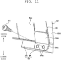
- a front cover 60B of the present embodiment does not include the first edge member 63 and the second edge member 64 (see FIG. 3 ).
- the front cover 60B of the present embodiment includes an edge member 80 made from an aluminum thin-plate, and a sandwiching unit 82 adapted to sandwich the edge member 80.
- the first recess 66 and the second recess 67 are not formed at the front surface of the front wall 62a.
- the edge member 80 configures the entire periphery of the edge part of the opening 61. At the front surface of the front wall 62a, the edge member 80 is arranged to overlap the peripheral region of the opening 61.
- the edge member 80 extends in an arch shape along the opening 61 when seen from the front side.
- the edge member 80 include a one side part, an opposite side part, and an upper end part.
- the one side part extends straight from the one end part of the edge member 80 toward the upper side, and then extends while inclining toward the inner side of the opening 61.
- the opposite side part extends straight from the other end part of the edge member 80 toward the upper side, and then extends while inclining toward the inner side of the opening 61.
- the upper end part is continuous to the upper ends of the one side part and the opposite side part and extends to the left and right.
- the edge member 80 is fixed to the front surface of the front wall 62a by, for example, adhesion using a double-sided tape.
- the edge member 80 may be fixed to the front wall 62a by other adhering method such as an adhesive, a one-sided tape, or the like.
- the edge member 80 includes a corner portion constituting the edge on the front side of the opening 61.
- the edge member 80 has hardness higher than hardness of the main body part 62, a fusion point higher than a fusion point of the main body part 62, and a surface roughness smaller than a surface roughness of the main body part 62.
- the sandwiching unit 82 includes a sandwiching plate (sandwiching member) 84 adapted to hold down the end part of the edge member 80 to the main body part 62 and sandwich the same, and a fixing block 86 adapted to fix the sandwiching plate 84 to the main body part 62 .
- a pair of sandwiching plates 84 is arranged. One sandwiching plate 84 holds down one end part of the edge member 80 toward the main body part 62 from the front side. The other sandwiching plate 84 holds down the other end part of the edge member 80 toward the main body part 62 from the front side.
- Each sandwiching plate 84 includes a contacting part 84a that is brought into contact with the edge member 80, and a coupling part 84c in which through holes 84b are arranged side by side and which is coupled to the fixing block 86.
- a pair of fixing blocks 86 is arranged in accordance with the sandwiching plates 84.
- a groove 86a to be fitted to the lower wall 62c of the main body part 62 is formed on the front surface of the fixing block 86.
- a screw hole 86b penetrating in the front-back direction is formed in the fixing block 86.
- the contacting part 84a of one sandwiching plate 84 is brought into contact with one end part of the edge member 80, and the contacting part 84a of the other sandwiching plate 84 is brought into contact with the other end part of the edge member 80.
- the lower wall 62c of the main body part 62 is fitted into the groove 86a of each fixing block 86.
- the screw hole 86b of the fixing block 86 associated with such a sandwiching plate 84 is arranged to be continuous.
- the sandwiching plate 84 and the fixing block 86 are tightened with respect to each other from the front and back by inserting a screw N1 from the front side into the through hole 84b and screw-fitting the screw N1 into the screw hole 86b.
- one sandwiching plate 84 and the main body part 62 sandwich one end part of the edge member 80, and the other sandwiching plate 84 and the main body part 62 sandwich the other end part of the edge member 80.
- the edge member 80 configuring the edge part of the opening 61 has each physical property described above (i.e., hardness higher than hardness of main body part 62, fusion point higher than fusion point of main body part 62, and surface roughness smaller than surface roughness of main body part 62).
- the front cover 60B can be prevented from being damaged.
- the edge member 80 extends in an arch shape along the opening 61 when seen from the front side, and is fixed to the front side of the main body part 62 by adhesion.
- a configuration in which the edge part of the opening 61 has each physical property described above can be easily realized using, for example, the front cover of the existing spinning unit.
- the sandwiching plate 84 sandwiches one end part of the edge member 80 together with the main body part 62.
- the sandwiching plate 84 sandwiches the other end part of the edge member 80 together with the main body part 62.
- the sandwiching plate 84 for sandwiching one end part of the edge member 80 and the sandwiching plate 84 for sandwiching the other end part of the edge member 80 have been provided, but only at least one of the two sandwiching plates 84 may be provided.
- a test was conducted for verifying which portion in the edge part of the opening 61 is easily damaged in removing the yarn Y entangled around the yarn accumulating roller 54. Specifically, after performing the removing operation of the yarn Y entangled around the yarn accumulating roller 54 for a predetermined number of times, the status of the edge part of the opening 61 was observed, and the proportion of the damage existing at each portion of the edge part of the opening 61 was obtained. The proportion of the damage was obtained with the damage over the entire periphery of the edge part of the opening 61 as a reference.
- Each portion of the edge part of the opening 61 in the verification test is a total of seven portions, a lower side portion of the one-side-edge-part, an upper side portion of the one-side-edge-part, an intermediate portion between the upper side portion and the lower side portion of the one-side-edge-part, a lower side portion of the opposite-side-edge-part, an upper side portion of the opposite-side-edge-part, an intermediate portion between the upper side portion and the lower side portion of the opposite-side-edge-part, and an upper edge part connecting to the upper side of the one-side-edge-part and the upper side of the opposite-side-edge-part and extending to the left and right.
- the order of the portion that is easily rubbed by the yarn Y and easily damaged is, "lower side portion of opposite-side-edge-part", “intermediate portion of opposite-side-edge-part”, “upper side portion of opposite-side-edge-part”, “lower side portion of one-side-edge-part”, “upper side portion of one-side-edge-part”, “intermediate portion of one-side-edge-part", and "upper edge part”.
- the first edge member 63 and the second edge member 64 configuring the one-side-edge-part and the opposite-side-edge-part of the opening 61 are arranged, and the first edge member 63 and the second edge member 64 have each physical property described above.
- the edge member 80 configuring the entire periphery of the edge part of the opening 61 is arranged, and the edge member 80 has each physical property described above.
- the present invention is not limited to such configuration.
- only at least one of the first edge member 63 and the second edge member 64 may be arranged.
- the first edge member 63 and the second edge member 64 merely need to have at least one of the physical properties described above.
- the edge member 80 merely needs to have at least one of the physical properties described above.
- at least a portion of the edge part of the opening 61 merely needs to have at least one of the physical properties of hardness higher than the hardness of the main body part 62, a fusion point higher than the fusion point of the main body part 62, and a surface roughness smaller than the surface roughness of the main body part 62.
- the first edge member 63 and the second edge member 64 each are fixed to the main body part 62 with the screw N, but the configuration of fixing the edge member to the main body part 62 is not particularly limited, and the edge member may be fixed to the main body part 62 by various publicly known configurations.
- an edge member 90 made from a sheet metal pressed article having a claw portion 91 may be used, and the edge member 90 may be fixed to the main body part 62 by bending the claw portion 91 and engaging the claw portion 91 to the main body part 62.
- the one-side-edge-part and the opposite-side-edge-part of the opening 61 are configured by the first edge member 63 and the second edge member 64 (see FIG. 3 ), which are different members from the main body part 62 .
- the edge part of the opening 61 is configured by the edge member 80 (see FIG. 10 ), which is a different member from the main body part 62.
- the edge part having at least one of the physical properties described above in the opening 61 may be integrally configured with the main body part 62.
- a portion 95 having at least one of the physical properties described above may be provided in at least a portion of the edge part of the opening 61 in the main body part 62 through a two-color molding.
- the front cover 60B can also be prevented from being damaged by providing at least one of the physical properties to the edge part of the opening 61. That is, a plated layer may be provided on the edge part of the opening 61 in the main body part 62.
- the edge part of the opening 61 of the main body part 62 may be coated with diamond like carbon (DLC). Modification treatment maybe performed on the edge part of the opening 61 of the main body part 62.
- DLC diamond like carbon
- the main body part 62 may be formed with ultraviolet curing resin, light curing resin, or thermosetting resin, and the edge part of the opening 61 of the main body part 62 may be subjected to ultraviolet irradiation, light irradiation, or heating.
- a wire W having at least one of the physical properties may be fitted along the opening 61 at a position of the corner portion constituting the edge on the front side of the opening 61 of the main body part 62 to form the corner portion with the wire W.
- the corner portion may be formed with the wire W through insert molding.
- Fig. 13C is a cross-sectional view of the cross-section parallel to the horizontal plane.
- the edge part of the opening 61 may include a chamfer portion constituting the edge on the front side of the opening 61 in place of the corner portion constituting the edge on the front side of the opening 61.
- the chamfer portion includes not only a chamfer portion having a plane (C plane) at the apex part, but also a chamfer portion having a curved surface (R surface) at the apex part.
- each device is arranged such that the yarn Y supplied on the upper side is wound on the lower side in a machine height direction, but each device may be arranged such that the yarn Y supplied from the lower side is wound on the upper side.
- FIG. 1 illustrates that the spinning machine 1 winds a cheese package P, but the spinning machine 1 can also wind a conical package P.
- the yarn accumulating device 50 has a function of pulling out the yarn Y from the pneumatic spinning device 7, but the yarn Y may be pulled out from the pneumatic spinning device 7 with a delivery roller and a nip roller.
- the tension sensor 9 may be arranged upstream of the yarn monitoring device 8.
- the unit controller 10 may be provided for every spinning unit 2. In the spinning unit 2, the waxing device 12, the tension sensor 9 and the yarn monitoring device 8 may be omitted.
- the opening 61 is prevented from being damaged.
- the fly waste and/or fiber waste caught at the damaged portion are avoided from mixing with the yarn Y and/or the package P, whereby the quality of the formed package P can be avoided from lowering.
Landscapes
- Engineering & Computer Science (AREA)
- Mechanical Engineering (AREA)
- Textile Engineering (AREA)
- Spinning Or Twisting Of Yarns (AREA)
Applications Claiming Priority (1)
| Application Number | Priority Date | Filing Date | Title |
|---|---|---|---|
| JP2016221752A JP2018080406A (ja) | 2016-11-14 | 2016-11-14 | 紡績ユニット及び紡績機 |
Publications (2)
| Publication Number | Publication Date |
|---|---|
| EP3321399A1 true EP3321399A1 (de) | 2018-05-16 |
| EP3321399B1 EP3321399B1 (de) | 2019-06-19 |
Family
ID=60186167
Family Applications (1)
| Application Number | Title | Priority Date | Filing Date |
|---|---|---|---|
| EP17198583.1A Not-in-force EP3321399B1 (de) | 2016-11-14 | 2017-10-26 | Spinneinheit und spinnmaschine |
Country Status (3)
| Country | Link |
|---|---|
| EP (1) | EP3321399B1 (de) |
| JP (1) | JP2018080406A (de) |
| CN (1) | CN108070930B (de) |
Citations (4)
| Publication number | Priority date | Publication date | Assignee | Title |
|---|---|---|---|---|
| JPH0562581U (ja) * | 1992-01-20 | 1993-08-20 | 村田機械株式会社 | 紡績装置におけるニップローラカバー |
| EP2573018A2 (de) * | 2011-09-20 | 2013-03-27 | Murata Machinery, Ltd. | Spinneinheit und Spinnmaschine |
| JP2013067891A (ja) | 2011-09-21 | 2013-04-18 | Murata Mach Ltd | 紡績ユニット及び紡績機 |
| EP2626323A2 (de) * | 2012-02-07 | 2013-08-14 | Murata Machinery, Ltd. | Garnansammlungsvorrichtung und Garnwickelvorrichtung damit |
Family Cites Families (8)
| Publication number | Priority date | Publication date | Assignee | Title |
|---|---|---|---|---|
| US4632324A (en) * | 1982-11-12 | 1986-12-30 | Mayer & Cie. Gmbh & Co. | Strand storing and delivering device |
| IT1263623B (it) * | 1993-02-23 | 1996-08-27 | Roj Electrotex Nuova Srl | Alimentatore di filo |
| DE4336994C1 (de) * | 1993-10-29 | 1995-03-30 | Heinrich Fabschitz | Fadenliefervorrichtung mit stufenlos einstellbarer Fadenabzugspannung |
| CN101343790A (zh) * | 2008-07-08 | 2009-01-14 | 苏州华绸科技有限公司 | 并丝加工的张力装置 |
| CN201326058Y (zh) * | 2008-10-29 | 2009-10-14 | 富源磁器股份有限公司 | 假捻机冷却板前后丝导的结构改良 |
| JP2013067874A (ja) * | 2011-09-20 | 2013-04-18 | Murata Mach Ltd | 紡績ユニット及び紡績装置 |
| CN104213276A (zh) * | 2014-08-12 | 2014-12-17 | 东华大学 | 一种基于双棍搓动的环锭纺细纱毛羽缠贴装置及用途 |
| JP2016055985A (ja) * | 2014-09-10 | 2016-04-21 | 村田機械株式会社 | 糸巻取装置 |
-
2016
- 2016-11-14 JP JP2016221752A patent/JP2018080406A/ja active Pending
-
2017
- 2017-10-26 EP EP17198583.1A patent/EP3321399B1/de not_active Not-in-force
- 2017-11-13 CN CN201711117777.6A patent/CN108070930B/zh active Active
Patent Citations (5)
| Publication number | Priority date | Publication date | Assignee | Title |
|---|---|---|---|---|
| JPH0562581U (ja) * | 1992-01-20 | 1993-08-20 | 村田機械株式会社 | 紡績装置におけるニップローラカバー |
| EP2573018A2 (de) * | 2011-09-20 | 2013-03-27 | Murata Machinery, Ltd. | Spinneinheit und Spinnmaschine |
| JP2013067872A (ja) | 2011-09-20 | 2013-04-18 | Murata Mach Ltd | 紡績ユニット及び紡績機 |
| JP2013067891A (ja) | 2011-09-21 | 2013-04-18 | Murata Mach Ltd | 紡績ユニット及び紡績機 |
| EP2626323A2 (de) * | 2012-02-07 | 2013-08-14 | Murata Machinery, Ltd. | Garnansammlungsvorrichtung und Garnwickelvorrichtung damit |
Also Published As
| Publication number | Publication date |
|---|---|
| CN108070930A (zh) | 2018-05-25 |
| EP3321399B1 (de) | 2019-06-19 |
| CN108070930B (zh) | 2021-08-24 |
| JP2018080406A (ja) | 2018-05-24 |
Similar Documents
| Publication | Publication Date | Title |
|---|---|---|
| EP2565307B1 (de) | Spinnmaschine | |
| EP3072840A1 (de) | Garnwickelmaschine und garnwickelverfahren | |
| EP2567922B1 (de) | Wachsvorrichtung, Spinneinheit und Spinnmaschine | |
| EP2749517B1 (de) | Spinnmaschine | |
| EP2876193B1 (de) | Reinigungsvorrichtung, Streckwerkvorrichtung und Spinneinheit | |
| EP2966200A2 (de) | Spinnmaschine und spinnverfahren | |
| EP2284301A1 (de) | Reinigungsvorrichtung für eine Streckrolle, Streckvorrichtung und Textilmaschine | |
| EP2966022B1 (de) | Garnwickelmaschine und garnwickelverfahren | |
| EP3075890B1 (de) | Streckvorrichtung und spinnmaschine | |
| EP3321399B1 (de) | Spinneinheit und spinnmaschine | |
| JP2013063807A (ja) | トラバースガイド、巻取ユニット、及び糸巻取機 | |
| CN110642095B (zh) | 纱线卷绕机 | |
| CN104229560B (zh) | 接纱装置、卷绕单元、纤维机械及接纱方法 | |
| EP3130553B1 (de) | Garnüberwachungsvorrichtung und garnwickelmaschine | |
| EP3040458B1 (de) | Core-garnzuführvorrichtung, spinnmaschine und verfahren zum zuführen von core-garn | |
| JP2010077577A (ja) | 繊維機械及びシャッター弁 | |
| EP3153613A1 (de) | Streckvorrichtung, spinnmaschine und verfahren zum spinnen | |
| EP2573230A2 (de) | Streckvorrichtung und Spinnmaschine | |
| EP3260585B1 (de) | Reinigungsvorrichtung für streckwalze | |
| JP2013230909A (ja) | 糸監視装置、及びこれを備える糸巻取ユニット | |
| CN205099835U (zh) | 导纱器、芯纱供给装置及纺纱机械 | |
| US20060277892A1 (en) | Core yarn production method and apparatus | |
| JP2016141561A (ja) | 吸引ノズル、及び当該吸引ノズルを備えた糸巻取装置 | |
| JP2016102267A (ja) | 繊維回収装置、ドラフト装置及び紡績機 | |
| JP2005248360A (ja) | クリール装置および一方向性プリプレグの製造装置および製造方法 |
Legal Events
| Date | Code | Title | Description |
|---|---|---|---|
| PUAI | Public reference made under article 153(3) epc to a published international application that has entered the european phase |
Free format text: ORIGINAL CODE: 0009012 |
|
| STAA | Information on the status of an ep patent application or granted ep patent |
Free format text: STATUS: THE APPLICATION HAS BEEN PUBLISHED |
|
| AK | Designated contracting states |
Kind code of ref document: A1 Designated state(s): AL AT BE BG CH CY CZ DE DK EE ES FI FR GB GR HR HU IE IS IT LI LT LU LV MC MK MT NL NO PL PT RO RS SE SI SK SM TR |
|
| AX | Request for extension of the european patent |
Extension state: BA ME |
|
| STAA | Information on the status of an ep patent application or granted ep patent |
Free format text: STATUS: REQUEST FOR EXAMINATION WAS MADE |
|
| 17P | Request for examination filed |
Effective date: 20180511 |
|
| RBV | Designated contracting states (corrected) |
Designated state(s): AL AT BE BG CH CY CZ DE DK EE ES FI FR GB GR HR HU IE IS IT LI LT LU LV MC MK MT NL NO PL PT RO RS SE SI SK SM TR |
|
| STAA | Information on the status of an ep patent application or granted ep patent |
Free format text: STATUS: EXAMINATION IS IN PROGRESS |
|
| 17Q | First examination report despatched |
Effective date: 20180816 |
|
| GRAP | Despatch of communication of intention to grant a patent |
Free format text: ORIGINAL CODE: EPIDOSNIGR1 |
|
| STAA | Information on the status of an ep patent application or granted ep patent |
Free format text: STATUS: GRANT OF PATENT IS INTENDED |
|
| INTG | Intention to grant announced |
Effective date: 20190212 |
|
| GRAS | Grant fee paid |
Free format text: ORIGINAL CODE: EPIDOSNIGR3 |
|
| GRAA | (expected) grant |
Free format text: ORIGINAL CODE: 0009210 |
|
| STAA | Information on the status of an ep patent application or granted ep patent |
Free format text: STATUS: THE PATENT HAS BEEN GRANTED |
|
| AK | Designated contracting states |
Kind code of ref document: B1 Designated state(s): AL AT BE BG CH CY CZ DE DK EE ES FI FR GB GR HR HU IE IS IT LI LT LU LV MC MK MT NL NO PL PT RO RS SE SI SK SM TR |
|
| REG | Reference to a national code |
Ref country code: GB Ref legal event code: FG4D |
|
| REG | Reference to a national code |
Ref country code: CH Ref legal event code: EP |
|
| REG | Reference to a national code |
Ref country code: IE Ref legal event code: FG4D |
|
| REG | Reference to a national code |
Ref country code: DE Ref legal event code: R096 Ref document number: 602017004658 Country of ref document: DE |
|
| REG | Reference to a national code |
Ref country code: CH Ref legal event code: NV Representative=s name: VALIPAT S.A. C/O BOVARD SA NEUCHATEL, CH Ref country code: AT Ref legal event code: REF Ref document number: 1145652 Country of ref document: AT Kind code of ref document: T Effective date: 20190715 |
|
| REG | Reference to a national code |
Ref country code: NL Ref legal event code: MP Effective date: 20190619 |
|
| PG25 | Lapsed in a contracting state [announced via postgrant information from national office to epo] |
Ref country code: SE Free format text: LAPSE BECAUSE OF FAILURE TO SUBMIT A TRANSLATION OF THE DESCRIPTION OR TO PAY THE FEE WITHIN THE PRESCRIBED TIME-LIMIT Effective date: 20190619 Ref country code: HR Free format text: LAPSE BECAUSE OF FAILURE TO SUBMIT A TRANSLATION OF THE DESCRIPTION OR TO PAY THE FEE WITHIN THE PRESCRIBED TIME-LIMIT Effective date: 20190619 Ref country code: LT Free format text: LAPSE BECAUSE OF FAILURE TO SUBMIT A TRANSLATION OF THE DESCRIPTION OR TO PAY THE FEE WITHIN THE PRESCRIBED TIME-LIMIT Effective date: 20190619 Ref country code: FI Free format text: LAPSE BECAUSE OF FAILURE TO SUBMIT A TRANSLATION OF THE DESCRIPTION OR TO PAY THE FEE WITHIN THE PRESCRIBED TIME-LIMIT Effective date: 20190619 Ref country code: AL Free format text: LAPSE BECAUSE OF FAILURE TO SUBMIT A TRANSLATION OF THE DESCRIPTION OR TO PAY THE FEE WITHIN THE PRESCRIBED TIME-LIMIT Effective date: 20190619 Ref country code: NO Free format text: LAPSE BECAUSE OF FAILURE TO SUBMIT A TRANSLATION OF THE DESCRIPTION OR TO PAY THE FEE WITHIN THE PRESCRIBED TIME-LIMIT Effective date: 20190919 |
|
| PGFP | Annual fee paid to national office [announced via postgrant information from national office to epo] |
Ref country code: CZ Payment date: 20190925 Year of fee payment: 3 |
|
| REG | Reference to a national code |
Ref country code: LT Ref legal event code: MG4D |
|
| PG25 | Lapsed in a contracting state [announced via postgrant information from national office to epo] |
Ref country code: GR Free format text: LAPSE BECAUSE OF FAILURE TO SUBMIT A TRANSLATION OF THE DESCRIPTION OR TO PAY THE FEE WITHIN THE PRESCRIBED TIME-LIMIT Effective date: 20190920 Ref country code: LV Free format text: LAPSE BECAUSE OF FAILURE TO SUBMIT A TRANSLATION OF THE DESCRIPTION OR TO PAY THE FEE WITHIN THE PRESCRIBED TIME-LIMIT Effective date: 20190619 Ref country code: RS Free format text: LAPSE BECAUSE OF FAILURE TO SUBMIT A TRANSLATION OF THE DESCRIPTION OR TO PAY THE FEE WITHIN THE PRESCRIBED TIME-LIMIT Effective date: 20190619 Ref country code: BG Free format text: LAPSE BECAUSE OF FAILURE TO SUBMIT A TRANSLATION OF THE DESCRIPTION OR TO PAY THE FEE WITHIN THE PRESCRIBED TIME-LIMIT Effective date: 20190919 |
|
| REG | Reference to a national code |
Ref country code: AT Ref legal event code: MK05 Ref document number: 1145652 Country of ref document: AT Kind code of ref document: T Effective date: 20190619 |
|
| PG25 | Lapsed in a contracting state [announced via postgrant information from national office to epo] |
Ref country code: AT Free format text: LAPSE BECAUSE OF FAILURE TO SUBMIT A TRANSLATION OF THE DESCRIPTION OR TO PAY THE FEE WITHIN THE PRESCRIBED TIME-LIMIT Effective date: 20190619 Ref country code: NL Free format text: LAPSE BECAUSE OF FAILURE TO SUBMIT A TRANSLATION OF THE DESCRIPTION OR TO PAY THE FEE WITHIN THE PRESCRIBED TIME-LIMIT Effective date: 20190619 Ref country code: EE Free format text: LAPSE BECAUSE OF FAILURE TO SUBMIT A TRANSLATION OF THE DESCRIPTION OR TO PAY THE FEE WITHIN THE PRESCRIBED TIME-LIMIT Effective date: 20190619 Ref country code: RO Free format text: LAPSE BECAUSE OF FAILURE TO SUBMIT A TRANSLATION OF THE DESCRIPTION OR TO PAY THE FEE WITHIN THE PRESCRIBED TIME-LIMIT Effective date: 20190619 Ref country code: SK Free format text: LAPSE BECAUSE OF FAILURE TO SUBMIT A TRANSLATION OF THE DESCRIPTION OR TO PAY THE FEE WITHIN THE PRESCRIBED TIME-LIMIT Effective date: 20190619 Ref country code: PT Free format text: LAPSE BECAUSE OF FAILURE TO SUBMIT A TRANSLATION OF THE DESCRIPTION OR TO PAY THE FEE WITHIN THE PRESCRIBED TIME-LIMIT Effective date: 20191021 |
|
| PGFP | Annual fee paid to national office [announced via postgrant information from national office to epo] |
Ref country code: DE Payment date: 20191021 Year of fee payment: 3 |
|
| PG25 | Lapsed in a contracting state [announced via postgrant information from national office to epo] |
Ref country code: IS Free format text: LAPSE BECAUSE OF FAILURE TO SUBMIT A TRANSLATION OF THE DESCRIPTION OR TO PAY THE FEE WITHIN THE PRESCRIBED TIME-LIMIT Effective date: 20191019 Ref country code: ES Free format text: LAPSE BECAUSE OF FAILURE TO SUBMIT A TRANSLATION OF THE DESCRIPTION OR TO PAY THE FEE WITHIN THE PRESCRIBED TIME-LIMIT Effective date: 20190619 Ref country code: SM Free format text: LAPSE BECAUSE OF FAILURE TO SUBMIT A TRANSLATION OF THE DESCRIPTION OR TO PAY THE FEE WITHIN THE PRESCRIBED TIME-LIMIT Effective date: 20190619 Ref country code: IT Free format text: LAPSE BECAUSE OF FAILURE TO SUBMIT A TRANSLATION OF THE DESCRIPTION OR TO PAY THE FEE WITHIN THE PRESCRIBED TIME-LIMIT Effective date: 20190619 |
|
| PG25 | Lapsed in a contracting state [announced via postgrant information from national office to epo] |
Ref country code: TR Free format text: LAPSE BECAUSE OF FAILURE TO SUBMIT A TRANSLATION OF THE DESCRIPTION OR TO PAY THE FEE WITHIN THE PRESCRIBED TIME-LIMIT Effective date: 20190619 |
|
| PG25 | Lapsed in a contracting state [announced via postgrant information from national office to epo] |
Ref country code: DK Free format text: LAPSE BECAUSE OF FAILURE TO SUBMIT A TRANSLATION OF THE DESCRIPTION OR TO PAY THE FEE WITHIN THE PRESCRIBED TIME-LIMIT Effective date: 20190619 Ref country code: PL Free format text: LAPSE BECAUSE OF FAILURE TO SUBMIT A TRANSLATION OF THE DESCRIPTION OR TO PAY THE FEE WITHIN THE PRESCRIBED TIME-LIMIT Effective date: 20190619 |
|
| PG25 | Lapsed in a contracting state [announced via postgrant information from national office to epo] |
Ref country code: MC Free format text: LAPSE BECAUSE OF FAILURE TO SUBMIT A TRANSLATION OF THE DESCRIPTION OR TO PAY THE FEE WITHIN THE PRESCRIBED TIME-LIMIT Effective date: 20190619 Ref country code: IS Free format text: LAPSE BECAUSE OF FAILURE TO SUBMIT A TRANSLATION OF THE DESCRIPTION OR TO PAY THE FEE WITHIN THE PRESCRIBED TIME-LIMIT Effective date: 20200224 |
|
| REG | Reference to a national code |
Ref country code: DE Ref legal event code: R097 Ref document number: 602017004658 Country of ref document: DE |
|
| PLBE | No opposition filed within time limit |
Free format text: ORIGINAL CODE: 0009261 |
|
| STAA | Information on the status of an ep patent application or granted ep patent |
Free format text: STATUS: NO OPPOSITION FILED WITHIN TIME LIMIT |
|
| PG2D | Information on lapse in contracting state deleted |
Ref country code: IS |
|
| PG25 | Lapsed in a contracting state [announced via postgrant information from national office to epo] |
Ref country code: LU Free format text: LAPSE BECAUSE OF NON-PAYMENT OF DUE FEES Effective date: 20191026 |
|
| 26N | No opposition filed |
Effective date: 20200603 |
|
| REG | Reference to a national code |
Ref country code: BE Ref legal event code: MM Effective date: 20191031 |
|
| PG25 | Lapsed in a contracting state [announced via postgrant information from national office to epo] |
Ref country code: SI Free format text: LAPSE BECAUSE OF FAILURE TO SUBMIT A TRANSLATION OF THE DESCRIPTION OR TO PAY THE FEE WITHIN THE PRESCRIBED TIME-LIMIT Effective date: 20190619 Ref country code: BE Free format text: LAPSE BECAUSE OF NON-PAYMENT OF DUE FEES Effective date: 20191031 |
|
| PG25 | Lapsed in a contracting state [announced via postgrant information from national office to epo] |
Ref country code: IE Free format text: LAPSE BECAUSE OF NON-PAYMENT OF DUE FEES Effective date: 20191026 Ref country code: FR Free format text: LAPSE BECAUSE OF NON-PAYMENT OF DUE FEES Effective date: 20191031 |
|
| REG | Reference to a national code |
Ref country code: DE Ref legal event code: R119 Ref document number: 602017004658 Country of ref document: DE |
|
| PG25 | Lapsed in a contracting state [announced via postgrant information from national office to epo] |
Ref country code: CY Free format text: LAPSE BECAUSE OF FAILURE TO SUBMIT A TRANSLATION OF THE DESCRIPTION OR TO PAY THE FEE WITHIN THE PRESCRIBED TIME-LIMIT Effective date: 20190619 |
|
| REG | Reference to a national code |
Ref country code: CH Ref legal event code: PL |
|
| PG25 | Lapsed in a contracting state [announced via postgrant information from national office to epo] |
Ref country code: LI Free format text: LAPSE BECAUSE OF FAILURE TO SUBMIT A TRANSLATION OF THE DESCRIPTION OR TO PAY THE FEE WITHIN THE PRESCRIBED TIME-LIMIT Effective date: 20201031 Ref country code: CH Free format text: LAPSE BECAUSE OF FAILURE TO SUBMIT A TRANSLATION OF THE DESCRIPTION OR TO PAY THE FEE WITHIN THE PRESCRIBED TIME-LIMIT Effective date: 20201031 |
|
| PG25 | Lapsed in a contracting state [announced via postgrant information from national office to epo] |
Ref country code: DE Free format text: LAPSE BECAUSE OF NON-PAYMENT OF DUE FEES Effective date: 20210501 Ref country code: CZ Free format text: LAPSE BECAUSE OF NON-PAYMENT OF DUE FEES Effective date: 20201026 Ref country code: HU Free format text: LAPSE BECAUSE OF FAILURE TO SUBMIT A TRANSLATION OF THE DESCRIPTION OR TO PAY THE FEE WITHIN THE PRESCRIBED TIME-LIMIT; INVALID AB INITIO Effective date: 20171026 Ref country code: MT Free format text: LAPSE BECAUSE OF FAILURE TO SUBMIT A TRANSLATION OF THE DESCRIPTION OR TO PAY THE FEE WITHIN THE PRESCRIBED TIME-LIMIT Effective date: 20190619 |
|
| GBPC | Gb: european patent ceased through non-payment of renewal fee |
Effective date: 20211026 |
|
| PG25 | Lapsed in a contracting state [announced via postgrant information from national office to epo] |
Ref country code: MK Free format text: LAPSE BECAUSE OF FAILURE TO SUBMIT A TRANSLATION OF THE DESCRIPTION OR TO PAY THE FEE WITHIN THE PRESCRIBED TIME-LIMIT Effective date: 20190619 |
|
| PG25 | Lapsed in a contracting state [announced via postgrant information from national office to epo] |
Ref country code: GB Free format text: LAPSE BECAUSE OF NON-PAYMENT OF DUE FEES Effective date: 20211026 |