EP3322263A1 - Générateur de swp (plasma à ondes de surface) couplé et refroidi par eau à câble coaxial - Google Patents
Générateur de swp (plasma à ondes de surface) couplé et refroidi par eau à câble coaxial Download PDFInfo
- Publication number
- EP3322263A1 EP3322263A1 EP17200087.9A EP17200087A EP3322263A1 EP 3322263 A1 EP3322263 A1 EP 3322263A1 EP 17200087 A EP17200087 A EP 17200087A EP 3322263 A1 EP3322263 A1 EP 3322263A1
- Authority
- EP
- European Patent Office
- Prior art keywords
- electromagnetic wave
- dielectric tube
- inner space
- antenna
- generator
- Prior art date
- Legal status (The legal status is an assumption and is not a legal conclusion. Google has not performed a legal analysis and makes no representation as to the accuracy of the status listed.)
- Granted
Links
Images


Classifications
-
- H—ELECTRICITY
- H01—ELECTRIC ELEMENTS
- H01J—ELECTRIC DISCHARGE TUBES OR DISCHARGE LAMPS
- H01J37/00—Discharge tubes with provision for introducing objects or material to be exposed to the discharge, e.g. for the purpose of examination or processing thereof
- H01J37/32—Gas-filled discharge tubes
- H01J37/32009—Arrangements for generation of plasma specially adapted for examination or treatment of objects, e.g. plasma sources
- H01J37/32192—Microwave generated discharge
- H01J37/32211—Means for coupling power to the plasma
- H01J37/32229—Waveguides
-
- H—ELECTRICITY
- H05—ELECTRIC TECHNIQUES NOT OTHERWISE PROVIDED FOR
- H05H—PLASMA TECHNIQUE; PRODUCTION OF ACCELERATED ELECTRICALLY-CHARGED PARTICLES OR OF NEUTRONS; PRODUCTION OR ACCELERATION OF NEUTRAL MOLECULAR OR ATOMIC BEAMS
- H05H1/00—Generating plasma; Handling plasma
- H05H1/24—Generating plasma
- H05H1/46—Generating plasma using applied electromagnetic fields, e.g. high frequency or microwave energy
-
- H—ELECTRICITY
- H01—ELECTRIC ELEMENTS
- H01J—ELECTRIC DISCHARGE TUBES OR DISCHARGE LAMPS
- H01J37/00—Discharge tubes with provision for introducing objects or material to be exposed to the discharge, e.g. for the purpose of examination or processing thereof
- H01J37/32—Gas-filled discharge tubes
- H01J37/32009—Arrangements for generation of plasma specially adapted for examination or treatment of objects, e.g. plasma sources
- H01J37/32192—Microwave generated discharge
- H01J37/32211—Means for coupling power to the plasma
- H01J37/3222—Antennas
-
- C—CHEMISTRY; METALLURGY
- C23—COATING METALLIC MATERIAL; COATING MATERIAL WITH METALLIC MATERIAL; CHEMICAL SURFACE TREATMENT; DIFFUSION TREATMENT OF METALLIC MATERIAL; COATING BY VACUUM EVAPORATION, BY SPUTTERING, BY ION IMPLANTATION OR BY CHEMICAL VAPOUR DEPOSITION, IN GENERAL; INHIBITING CORROSION OF METALLIC MATERIAL OR INCRUSTATION IN GENERAL
- C23C—COATING METALLIC MATERIAL; COATING MATERIAL WITH METALLIC MATERIAL; SURFACE TREATMENT OF METALLIC MATERIAL BY DIFFUSION INTO THE SURFACE, BY CHEMICAL CONVERSION OR SUBSTITUTION; COATING BY VACUUM EVAPORATION, BY SPUTTERING, BY ION IMPLANTATION OR BY CHEMICAL VAPOUR DEPOSITION, IN GENERAL
- C23C16/00—Chemical coating by decomposition of gaseous compounds, without leaving reaction products of surface material in the coating, i.e. chemical vapour deposition [CVD] processes
- C23C16/22—Chemical coating by decomposition of gaseous compounds, without leaving reaction products of surface material in the coating, i.e. chemical vapour deposition [CVD] processes characterised by the deposition of inorganic material, other than metallic material
- C23C16/26—Deposition of carbon only
- C23C16/27—Diamond only
- C23C16/274—Diamond only using microwave discharges
-
- H—ELECTRICITY
- H01—ELECTRIC ELEMENTS
- H01J—ELECTRIC DISCHARGE TUBES OR DISCHARGE LAMPS
- H01J37/00—Discharge tubes with provision for introducing objects or material to be exposed to the discharge, e.g. for the purpose of examination or processing thereof
- H01J37/32—Gas-filled discharge tubes
- H01J37/32009—Arrangements for generation of plasma specially adapted for examination or treatment of objects, e.g. plasma sources
- H01J37/32192—Microwave generated discharge
- H01J37/32293—Microwave generated discharge using particular waveforms, e.g. polarised waves
-
- H—ELECTRICITY
- H01—ELECTRIC ELEMENTS
- H01J—ELECTRIC DISCHARGE TUBES OR DISCHARGE LAMPS
- H01J37/00—Discharge tubes with provision for introducing objects or material to be exposed to the discharge, e.g. for the purpose of examination or processing thereof
- H01J37/32—Gas-filled discharge tubes
- H01J37/32431—Constructional details of the reactor
- H01J37/32458—Vessel
- H01J37/32522—Temperature
-
- H—ELECTRICITY
- H05—ELECTRIC TECHNIQUES NOT OTHERWISE PROVIDED FOR
- H05H—PLASMA TECHNIQUE; PRODUCTION OF ACCELERATED ELECTRICALLY-CHARGED PARTICLES OR OF NEUTRONS; PRODUCTION OR ACCELERATION OF NEUTRAL MOLECULAR OR ATOMIC BEAMS
- H05H1/00—Generating plasma; Handling plasma
- H05H1/24—Generating plasma
- H05H1/46—Generating plasma using applied electromagnetic fields, e.g. high frequency or microwave energy
- H05H1/461—Microwave discharges
- H05H1/4615—Microwave discharges using surface waves
-
- H—ELECTRICITY
- H05—ELECTRIC TECHNIQUES NOT OTHERWISE PROVIDED FOR
- H05H—PLASMA TECHNIQUE; PRODUCTION OF ACCELERATED ELECTRICALLY-CHARGED PARTICLES OR OF NEUTRONS; PRODUCTION OR ACCELERATION OF NEUTRAL MOLECULAR OR ATOMIC BEAMS
- H05H1/00—Generating plasma; Handling plasma
- H05H1/24—Generating plasma
- H05H1/46—Generating plasma using applied electromagnetic fields, e.g. high frequency or microwave energy
- H05H1/461—Microwave discharges
- H05H1/463—Microwave discharges using antennas or applicators
-
- H—ELECTRICITY
- H05—ELECTRIC TECHNIQUES NOT OTHERWISE PROVIDED FOR
- H05H—PLASMA TECHNIQUE; PRODUCTION OF ACCELERATED ELECTRICALLY-CHARGED PARTICLES OR OF NEUTRONS; PRODUCTION OR ACCELERATION OF NEUTRAL MOLECULAR OR ATOMIC BEAMS
- H05H1/00—Generating plasma; Handling plasma
- H05H1/24—Generating plasma
- H05H1/46—Generating plasma using applied electromagnetic fields, e.g. high frequency or microwave energy
- H05H1/461—Microwave discharges
- H05H1/4637—Microwave discharges using cables
Definitions
- the present invention relates to a surface wave plasma SWP generator and more particularly to a coaxial-cable coupled and water-cooled SWP (surface wave plasma) generator.
- the surface wave plasma SWP is generated by a surface wave being propagated to an interface between the plasma and the dielectric.
- the surface wave plasma enables dense plasma.
- an electromagnetic wave generator applicator or an antenna is located outside a plasma chamber. Therefore, the surface wave plasma approach may lead to a very simple, efficient and flexible configuration as compared to the conventional RF plasma approach.
- the SWP approach may operate in a very wide pressure range from tens of mTorr to an atmospheric pressure.
- the SWP plasma density may range from about 10E8 to 10E15 cm -3 .
- the SWP also has a higher electron temperature and thus is more efficient in molecular dissociation and radical generation than in the conventional DC/RF approach.
- the surface wave plasma may be widely applied to semiconductor processing fields such as remote cleaning, radical generation, decomposition/reduction of greenhouse gases SF 6 , CF 4 , PFC, etc., semiconductor passivation, and film removal, etc.
- a plasma generator in a surfaguide approach, which is a typical example of the surface wave plasma approach, includes a dielectric discharge tube 20 and a waveguide 10 for transmitting an electromagnetic wave to the discharge tube 20 as shown in FIG. 1 .
- the dielectric discharge tube 20 extends perpendicularly to the waveguide 10 and communicates with the waveguide 10.
- the discharge tube 20 is made of a dielectric through which electromagnetic waves can pass.
- a discharge gas is injected into the discharge tube 20.
- the electromagnetic wave transmitted through the waveguide 10 is introduced into the discharge tube 20.
- the electromagnetic wave introduced into the discharge tube 20 reacts with the discharge gas injected into the discharge tube 20, thereby generating plasma inside the discharge tube 20.
- the surface wave plasma generator shown in FIG. 1 in order to generate the surface wave plasma, electromagnetic waves must be transmitted to the discharged gas through the dielectric. As a result, since the generated plasma has a very high thermal energy, it is necessary to efficiently cool the dielectric discharge tube to prevent discharge tube rupture and damage. To do this, the surface wave plasma discharge tube has a double tube structure for injecting cooling fluid. As a result, the cooling fluid flows between an inner tube and an outer tube of the dual tube structure.
- Cooling of the dielectric discharge tube is usually sufficient by air-cooling when the plasma density is low. However, when the plasma density is high, direct cooling by the cooling fluid is efficient. However, in terms of transmission of electromagnetic waves, the presence of the cooling fluid between the inner tube and the outer tube lowers the efficiency of electromagnetic wave transmission.
- the cooling fluid may be mainly classified into dielectric oil and deionized water.
- dielectric oil the electromagnetic wave transmission efficiency is excellent due to the low loss tangent of the dielectric.
- cooling cycles with high pressure and large flow rate are required. This requires an additional oil chiller that requires high power consumption.
- oil cooling fluids can be a major source of contamination in semiconductor/display processes where cleanliness is paramount. For this reason, it is not preferable to use oil as the cooling fluid.
- de-ionized water is used as the cooling fluid.
- Such de-ionized water has good cooling efficiency, but does not have dielectric properties of high purity as dielectric oil.
- the use of de-ionized water leads to higher energy losses than using the dielectric oil. Therefore, in designing the discharge tube, it is necessary to design the discharge tube that minimizes the electromagnetic wave loss.
- a major disadvantage of the cooling system using such a refrigerant is that, when cracks occur in the dielectric discharge tube, the cooling fluid can leak directly into the chamber. There is a need to fundamentally solve this problem.
- Such a discharge tube structure of the surface wave plasma apparatus leads to a limitation in a power of the applied electromagnetic wave, hence, limitation of the processed gas flow rate, and a reduction of the amount of radicals that can be generated.
- the surface wave plasma may be limited in terms of its performance, operating range and applications.
- the conventional surface wave plasma apparatus uses the waveguide. That is, a transmission line for transmitting electromagnetic waves from the magnetron to the plasma discharge tube is constructed using a waveguide in a form of a fixed tube.
- a transmission line for transmitting electromagnetic waves from the magnetron to the plasma discharge tube is constructed using a waveguide in a form of a fixed tube.
- the present disclosure is to provide a coaxial-cable coupled and water-cooled SWP (surface wave plasma) generator wherein transmission of electromagnetic waves is implemented using a coaxial cable so that there is no restriction on installation space and transmission distance of electromagnetic waves, or an electromagnetic wave transmission line is constructed so that flexible movement thereof can be performed as needed.
- SWP surface wave plasma
- the present disclosure is to provide a coaxial-cable coupled and water-cooled SWP (surface wave plasma) generator wherein a dimension of the surface wave plasma SWP generator is reduced, the cooling fluid does not flow into the dielectric tube in spite of cracks in the dielectric tube, the electromagnetic wave input into the dielectric tube is not lost by the cooling fluid, and it is possible to efficiently transmit the electromagnetic wave into the dielectric tube without loss of the electromagnetic wave.
- SWP surface wave plasma
- a coaxial-cable coupled and water-cooled SWP (surface wave plasma) generator comprising: a hollow connector having a first inner space defined therein; a coaxial-cable connected to the hollow connector, wherein the cable has a core configured to transmit an electromagnetic wave from an electromagnetic wave oscillating unit to the hollow connector, wherein the core extends into the inner space of the hollow connector; a dielectric tube having a first end portion electromagnetically coupled to the hollow connector so that the electromagnetic wave transmitted into the hollow connector is electromagnetically inputted into the dielectric tube; and a discharge gas injection unit fluid-communicating with the dielectric tube to inject a discharge gas into the dielectric tube.
- SWP surface wave plasma
- the discharge gas injection unit fluid-communicates with the dielectric tube at a position adjacent to the first end portion of the tube.
- the generator further includes a cooling jacket including a hollow tube body having a second inner space defined by a surrounding wall thereof, wherein the dielectric tube is at least partially inserted into the second inner space such that an inner face of the wall contacts an outer face of the dielectric tube, wherein the cooling jacket include a coolant channel defined between the inner face and an outer face of the wall, and the coolant channel extends in a length direction of the hollow tube body and along a circumference of the hollow tube body, wherein a coolant fluid flows along the coolant channel.
- the hollow connector has a first open side end facing the dielectric tube, wherein the first end portion of the dielectric tube passes through the first open side end of the connector and into the first inner space of the connector, wherein the first end portion is electromagnetically coupled to the hollow connector.
- the generator further includes an electromagnetic wave emission antenna, wherein the electromagnetic wave emission antenna has first and second opposite ends, wherein the first end of the antenna is coupled to the core of the coaxial-cable and the second end of the antenna is inserted into or passes through the first inner space of the hollow connector, wherein the second end of the antenna faces the first end portion of the dielectric tube.
- the second end of the antenna is spaced from or contacts the first end portion of the dielectric tube.
- a length between the first and second ends of the electromagnetic wave emission antenna is at least one-half a width of the hollow connector, wherein the width direction is parallel to a direction of extension of the electromagnetic wave emission antenna; and wherein the second end of the antenna is spaced from or contacts the first end portion of the dielectric tube, and wherein the first end portion of the dielectric tube is inserted into the second inner space of the cooling jacket; or wherein the first end portion of the dielectric tube passes through a first open side end of the connector and into the first inner space of the connector.
- a thickness or diameter of the electromagnetic wave emission antenna is smaller than an inner diameter of the dielectric tube.
- the generator further includes an electromagnetic wave transmission member disposed in the first inner space, wherein the first end portion of the dielectric tube passes through a first open side end of the connector and into the first inner space of the connector, wherein the second end of the antenna is inserted into the first inner space of the hollow connector, wherein the electromagnetic wave transmission member surrounds the first end portion of the dielectric tube, and surrounds the second end of the antenna.
- the generator further includes an electromagnetic wave transmission member disposed in the first inner space; and a cooling jacket including a hollow tube body having a second inner space defined by a surrounding wall thereof, wherein the dielectric tube is received in the second inner space; wherein the second end of the antenna is inserted into the first inner space of the hollow connector, wherein the first end portion of the dielectric tube is received in the second inner space, wherein the electromagnetic wave transmission member contacts the first end portion of the dielectric tube, and surrounds the second end of the antenna.
- the generator further includes an electromagnetic wave transmission member disposed in the first inner space; and a cooling jacket including a hollow tube body having a second inner space defined by a surrounding wall thereof, wherein the dielectric tube is received in the second inner space; wherein the second end of the antenna passes through the first inner space of the hollow connector and is inserted into the second inner space; wherein the first end portion of the dielectric tube is received in the second inner space, wherein the electromagnetic wave transmission member is partially formed in the second inner space, wherein the electromagnetic wave transmission member contacts the first end portion of the dielectric tube, and surrounds the second end of the antenna.
- the transmission of electromagnetic waves is implemented using the coaxial cable so that there is no restriction on installation space and transmission distance of electromagnetic waves, or an electromagnetic wave transmission line is constructed so that flexible movement thereof can be performed as needed.
- the dimension of the surface wave plasma SWP generator is reduced compared to the conventional the surface wave plasma SWP generator, the cooling fluid does not flow into the dielectric tube in spite of cracks in the dielectric tube, the electromagnetic wave input into the dielectric tube is not lost by the cooling fluid, and it is possible to efficiently transmit the electromagnetic wave into the dielectric tube without loss of the electromagnetic wave.
- spatially relative terms such as “beneath,” “below,” “lower,” “under,” “above,” “upper,” and the like, may be used herein for ease of explanation to describe one element or feature's relationship to another element s or feature s as illustrated in the figures. It will be understood that the spatially relative terms are intended to encompass different orientations of the device in use or in operation, in addition to the orientation depicted in the figures. For example, if the device in the figures is turned over, elements described as “below” or “beneath” or “under” other elements or features would then be oriented “above” the other elements or features. Thus, the example terms “below” and “under” can encompass both an orientation of above and below. The device may be otherwise oriented for example, rotated 90 degrees or at other orientations, and the spatially relative descriptors used herein should be interpreted accordingly.
- FIGS. 2A and 2B are perspective views showing appearance of a coaxial-cable coupled and water-cooled SWP generator according to an embodiment of the present invention.
- FIG. 3 is a cross-sectional view of the coaxial-cable coupled and water-cooled surface wave plasma SWP generator shown in FIG. 2 . More specifically,
- FIG. 3 is a cross-sectional view showing an example of an electromagnetic wave coupling state of a dielectric tube through an electromagnetic wave emission antenna for a coaxial-cable coupled and water-cooled SWP generator according to an embodiment of the present invention.
- the coaxial-cable coupled and water-cooled SWP (surface wave plasma) generator includes a hollow connector 100, a coaxial cable 200, a dielectric tube 300, and a discharge gas injection unit 400.
- the hollow connector 100 has an internal space defined therein for confining therein electromagnetic waves incident thereto from the outside.
- the hollow connector 100 may be in the form of a rectangular parallelepiped or a cuboid, as shown in FIG. 2A , or may be in the shape of a cylinder, as shown in FIG. 2B .
- the coaxial cable 200 transmits electromagnetic waves into the hollow connector 100.
- the coaxial cable 200 includes the core 210 for transmitting electromagnetic waves generated from an electromagnetic wave oscillation unit (not shown).
- the distal end of the core is positioned inside the hollow connector 100 so that the core 210 transmits the electromagnetic wave generated from the electromagnetic wave oscillation unit to the inside of the hollow connector 100.
- the coaxial cable 200 comprises a core 210, an insulating layer 220 made of a flexible material surrounding the core 210, a flexible outer conductive coating 240 surrounding the insulating layer, and a distal end connector 230 disposed on a distal end of the outer conductive coating 240 and the insulating layer 220.
- the core 210 may extend beyond the distal end connector 230 into the hollow connector 100.
- the distal end connector 230 may be fixed to one side of the hollow connector 100, and the core 210 may be inserted into the hollow connector 100.
- the dielectric tube 300 has an inner space therein defined therein, in which electromagnetic waves and discharge gases react with each other to produce high-temperature plasma.
- the dielectric tube 300 is electromagnetic wave-coupled to the hollow connector 100 to receive electromagnetic waves therein.
- the dielectric tube 300 has an inner end facing the hollow connector 100.
- the hollow connector 100 has an inner end facing the dielectric tube 300.
- the hollow connector 100 has an outer end that partially accommodates the coaxial cable 200.
- the inner end of the hollow connector 100 is open. Therefore, the inner end of the dielectric tube 300 passes through the inner end of the hollow connector 100 and then into the inner space of the hollow connector 100.
- an electromagnetic wave coupling state in which an electromagnetic wave inputted into the hollow connector 100 may be inputted through the inserted portion of the dielectric tube 300 into the hollow connector 100 into the inner space of the dielectric tube 300.
- the shape of the dielectric tube 300 is not particularly limited.
- the dielectric tube 300 may be cylindrical.
- electromagnic wave receiving end-portion 310 the inner end of the dielectric tube 300 connected to the hollow connector 100 and receiving the electromagnetic waves.
- the discharge gas injection unit 400 is in fluid-communication with the dielectric tube 300 to inject a discharge gas into the dielectric tube 300.
- the discharge gas injection unit 400 may include a gas injection tube 410 connected to the dielectric tube 300 and a gas injector 420 provided at an upper end of the gas injection tube 410.
- the discharge gas injection tube 410 is disposed adjacent to the electromagnetic wave receiving end-portion 310 of the dielectric tube 300 connected to the hollow connector 100, so that the discharge gas readily reacts with the electromagnetic waves to generate plasma.
- the coaxial-cable coupled and water-cooled SWP (surface wave plasma) generator may further include a cooling jacket 500.
- the cooling jacket 500 is configured to cool the dielectric tube 300.
- the cooling jacket 500 is in the form of a hollow tube with an inner diameter that can wrap around the dielectric tube 300.
- the inner surface of the hollow portion thereof contacts the outer surface of the dielectric tube 300 and surrounds the dielectric tube 300.
- the length of the cooling jacket 500 is not particularly limited.
- the length of the jacket may have a length that can cover the entire length or a portion of the portion of the dielectric tube 300 extending outside the hollow connector 100. In one embodiment, as shown in FIG.
- the cooling jacket 500 may be configured to wrap the entire length of the portion of the dielectric tube 300 extending outside the hollow connector 100.
- This cooling jacket 500 includes a coolant channel 510 for circulating the coolant fluid to cool the dielectric tube 300 as previously mentioned.
- the coolant channel 510 is configured to allow the coolant fluid to flow along the longitudinal and circumferential directions of the cooling jacket 500.
- the coolant channel 510 has a circular ring shape when viewed from a cross-section perpendicular to the axial direction of the cooling jacket 500.
- the circular ring shape extends along the longitudinal direction of the cooling jacket 500.
- the coolant channel 510 has a cylindrical shape.
- the coolant channel 510 is located between the inner and outer surfaces of the cooling jacket 500 and does not contact the outer surface of the dielectric tube 300.
- the coolant fluid traveling along the coolant channel 510 may flow only within the cooling jacket 500 without contacting the dielectric tube 300.
- the coolant channel 510 may include an inlet 510a and an outlet 510b to allow the coolant fluid to circulate into and out of the cooling jacket 500.
- the cooling jacket 500 may also be made of a highly conductive metal material to cool the dielectric tube 300 while surrounding the dielectric tube 300.
- the cooling jacket 500 may be made of aluminum.
- the coaxial-cable coupled and water-cooled SWP generator includes an electromagnetic wave emission antenna 600 and an electromagnetic wave transmission member 700 to efficiently transmit the electromagnetic waves to the dielectric tube 300.
- the electromagnetic wave emission antenna 600 has an outer end connected to the core 210 of the coaxial cable 200 and the inner end inserted into the hollow connector 100 so as to face away the electromagnetic wave receiving end-portion 310. That is, the electromagnetic wave emission antenna 600 extends, inside the hollow connector 100, from the outer side end of the hollow connector 100 toward the electromagnetic wave receiving end-portion 310 of the dielectric tube 300 disposed at the inner side end of the connector 100.
- the electromagnetic wave emission antenna 600 may have a columnar shape, for example, a cylindrical shape.
- the electromagnetic wave emission antenna 600 emits the electromagnetic waves received from the core 210 toward the electromagnetic wave receiving end-portion 310 of the dielectric tube 300, thereby inputting electromagnetic waves into the dielectric tube 300.
- the extension length of the electromagnetic wave emission antenna 600 may be configured to allow the antenna 600 to be spaced apart or in contact with the electromagnetic wave receiving end-portion 310 of the dielectric tube 200.
- the extension length of the electromagnetic wave emission antenna 600 may be at least one-half a width C (between the inner and outer side faces) of the hollow connector 100 parallel to the direction of extension of the electromagnetic wave emission antenna 600.
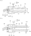
- FIG. 4 is a cross-sectional view showing another example of an electromagnetic wave coupling state of a dielectric tube through an electromagnetic wave emission antenna for a coaxial-cable coupled and water-cooled SWP generator according to an embodiment of the present invention.
- FIG. 5 is a cross-sectional view illustrating still another example of an electromagnetic wave coupling state of a dielectric tube through an electromagnetic wave emission antenna for a coaxial-cable coupled and water-cooled SWP generator according to an embodiment of the present invention.
- FIG. 3 is a cross-sectional view showing one example of an electromagnetic wave coupling state of a dielectric tube through an electromagnetic wave emission antenna for a coaxial-cable coupled and water-cooled SWP generator according to an embodiment of the present invention.
- the electromagnetic wave emission antenna 600 may be referred to as a first the electromagnetic wave emission antenna 600.
- the extension length of the electromagnetic wave emission antenna 600 may substantially one-half a width C (between the inner and outer side faces) of the hollow connector 100 parallel to the direction of extension of the electromagnetic wave emission antenna 600.
- the portion inserted into the hollow connector 100 of the electromagnetic wave receiving end-portion 310 of the dielectric tube 300 may be spaced apart from the electromagnetic wave emission antenna 600.
- the extension length of the electromagnetic wave emission antenna 600 may substantially the width C (between the inner and outer side faces) of the hollow connector 100 parallel to the direction of extension of the electromagnetic wave emission antenna 600.
- the portion inserted into the hollow connector 100 of the electromagnetic wave receiving end-portion 310 of the dielectric tube 300 may be spaced apart from the electromagnetic wave emission antenna 600.
- the electromagnetic wave receiving end-portion 310 of the dielectric tube 300 is located inside the cooling jacket 500 and is positioned close to the electromagnetic wave emission antenna 600.
- the electromagnetic wave emission antenna 600 may be referred to as a second electromagnetic wave emission antenna 600.
- the extension length of the electromagnetic wave emission antenna 600 may exceed the width C (between the inner and outer side faces) of the hollow connector 100 parallel to the direction of extension of the electromagnetic wave emission antenna 600. That is, the electromagnetic wave emission antenna 600 may extend through the open inner side end of the connector 100 and then extend into in the inner space of the cooling jacket 500. In this connection, the portion of the electromagnetic wave emission antenna 600 inserted into the inner space of the cooling jacket 500 may be spaced apart from the electromagnetic wave receiving end-portion 310 of the dielectric tube 300. In this connection, the electromagnetic wave receiving end-portion 310 of the dielectric tube 300 is located in the inner space of the cooling jacket 500 and is positioned close to the electromagnetic wave emission antenna 600. In this embodiment, the electromagnetic wave emission antenna 600 may be referred to as a third electromagnetic wave emission antenna 600.
- a thickness or diameter A of the first, second and/or third electromagnetic wave emission antenna 600 is less than the inner diameter B of the dielectric tube 300. Since the thickness or diameter A of the first, second and/or third electromagnetic wave emission antenna 600 is less than the inner diameter B of the dielectric tube 300, the electromagnetic waves emitted from the first, second and/or third electromagnetic wave emission antenna 600 may be uniformly radiated over the entire radial region of the dielectric tube 300.
- the electromagnetic wave transmission member 700 connects the electromagnetic wave emission antenna 600 and the dielectric tube 300.
- the electromagnetic wave transmission member 700 may be disposed within the hollow connector 100 so as to surround the first electromagnetic wave emission antenna 600 and the electromagnetic wave receiving end portion 310 of the dielectric tube 300 inserted into the hollow connector 100.
- the electromagnetic wave transmission member 700 may be disposed within the hollow connector 100 so as to surround the entire second electromagnetic wave emission antenna 600, and contact the electromagnetic wave receiving end portion 310 of the dielectric tube 300.
- the electromagnetic wave transmission member 700 may be disposed within the hollow connector 100 so as to surround the entire second electromagnetic wave emission antenna 600, and to be inserted into the inner space of the cooling jacket 500 to contact the electromagnetic wave receiving end portion 310 of the dielectric tube 300.
- the electromagnetic wave transmission member 700 is made of a dielectric. Since the electromagnetic wave transmission member 700 is made of a dielectric, the electromagnetic waves transmitted inside the hollow connector 100 may be transmitted from the electromagnetic wave emission antenna 600 via the electromagnetic wave transmission member 700 to the dielectric tube 300.
- SWP surface wave plasma
- electromagnetic waves generated from an electromagnetic wave oscillating unit are transmitted via the core 210 of the coaxial cable 200 and input into the hollow connector 100.
- discharge gas is injected from the discharge gas injection unit 400 into the dielectric tube 300.
- the electromagnetic wave transmitted to the inside of the hollow connector 100 is radiated toward the electromagnetic wave receiving end-portion 310 of the dielectric tube 300 via the electromagnetic wave emission antenna 600 connected to the core 210 of the coaxial-cable 200.
- the electromagnetic wave emission antenna 600 and/or the electromagnetic wave receiving end-portion 310 of the dielectric tube 300 are surrounded by the electromagnetic wave transmission member 700.
- the electromagnetic wave transmitted to the hollow connector 100 may be efficiently transmitted to the electromagnetic wave emission antenna 600 and, thus, the electromagnetic wave radiated from the electromagnetic wave emission antenna 600 may be effectively and efficiently transmitted to the electromagnetic wave receiving end portion 310 of the dielectric tube 300 via the electromagnetic wave transmission member 700. In this way, the electromagnetic waves are input into the dielectric tube 300.
- the electromagnetic waves input into the dielectric tube 300 react with the discharge gas injected from the discharge gas injection unit 400 into the dielectric tube 300 to generate a high-temperature plasma.
- the coolant fluid is injected into the inlet 510a of the coolant channel 510 to cool the dielectric tube 300 with the elevated temperature through the resulting hot plasma.
- the coolant fluid injected into the coolant channel 510 travels along the coolant channel 510 and along the length and circumferential directions of the cooling jacket 500.
- the cooling jacket 500 is cooled, and, then, the lowered heat of the cooling jacket 500 is conducted to the dielectric tube 300 to cool the dielectric tube 300.
- the coolant fluid passing through the coolant channel 510 is discharged through the outlet 510b of the coolant channel 510 to the outside of the cooling jacket 500.
- the fluid may be collected from a coolant fluid supply illustrated previously, and then fed back to the inlet 510a of the coolant channel 510. Thereby, cooling fluid circulation is achieved.
- the dielectric tube 300 and the electromagnetic wave oscillation unit (not shown) far away from the dielectric tube 300 may be coupled to each other via the coaxial-cable 200, which has a flexible nature.
- the flexible coaxial-cable 200 may allow easy flexible connection between the dielectric tube 300 and the electromagnetic wave oscillator, and/or allow reliable transmission of the electromagnetic waves to the dielectric tube 300, and allow easy movement of the plasma generator, and/or facilitate the installation of the plasma generator.
- the transmission line between the electromagnetic wave oscillation unit and the dielectric tube 300 can be easily constructed using the flexible coaxial cable 200.
- the waveguide may be omitted. Further, the electromagnetic wave is transmitted via the electromagnetic wave emission antenna 600 located inside the hollow connector 100 toward the end of the dielectric tube 300.
- the present surface wave plasma generator may have a reduced size in comparison with the conventional surface wave plasma generator having a configuration in which the wave guide passes through perpendicularly the discharge tube.
- the dielectric tube 300 is surrounded by the cooling jacket 500, and the inner surface of the discharge inner space defined in the cooling jacket 500 contacts the outer surface of the dielectric tube 300.
- the coolant fluid circulates through the coolant channel 510 formed inside a body of the cooling jacket 500. This allows indirect cooling of the dielectric tube 300 via the thermal conduction of the cooling jacket 500. This prevents the coolant fluid from leaking into the dielectric tube 300, even when the dielectric tube 300 is in continuous contact with a hot plasma for a long time and cracking occurs in the tube 300.
- the electromagnetic waves may be transmitted toward the end portion 310 of the dielectric tube 300 through the electromagnetic wave emission antenna 600 located inside the hollow connector 100.
- the coolant fluid does not flow into the hollow connector 100, so that the power of electromagnetic waves input to the dielectric tube 300 is prevented from being lost by the coolant fluid.
- the extension length of the electromagnetic wave emission antenna 600 may be configured to allow the antenna 600 to be spaced apart or in contact with the electromagnetic wave receiving end-portion 310 of the dielectric tube 200.
- the extension length of the electromagnetic wave emission antenna 600 may be at least one-half the width C (between the inner and outer side faces) of the hollow connector 100 parallel to the direction of extension of the electromagnetic wave emission antenna 600.
- the thickness or diameter A of the first, second and/or third electromagnetic wave emission antenna 600 is less than the inner diameter B of the dielectric tube 300.
- the electromagnetic waves emitted from the first, second and/or third electromagnetic wave emission antenna 600 may be uniformly radiated over the entire radial region of the dielectric tube 300.
- the electromagnetic wave emission antenna 600 can efficiently transmit the power of the electromagnetic wave to the dielectric tube 300 without loss thereof.
- the electromagnetic wave transmission member 700 made of a dielectric surrounds the electromagnetic wave emission antenna 600 in the hollow connector 100, there is an advantage that the antenna 600 may efficiently transmit the electromagnetic waves transmitted in the hollow connector 100 via the electromagnetic wave transmission member 700 to the dielectric tube 300 without loss.
Landscapes
- Physics & Mathematics (AREA)
- Engineering & Computer Science (AREA)
- Plasma & Fusion (AREA)
- Chemical & Material Sciences (AREA)
- Analytical Chemistry (AREA)
- Electromagnetism (AREA)
- Spectroscopy & Molecular Physics (AREA)
- Inorganic Chemistry (AREA)
- Chemical Kinetics & Catalysis (AREA)
- Materials Engineering (AREA)
- Mechanical Engineering (AREA)
- Metallurgy (AREA)
- Organic Chemistry (AREA)
- General Chemical & Material Sciences (AREA)
- Plasma Technology (AREA)
Applications Claiming Priority (1)
| Application Number | Priority Date | Filing Date | Title |
|---|---|---|---|
| KR1020160150205A KR101830007B1 (ko) | 2016-11-11 | 2016-11-11 | 동축 케이블 연결형 수냉식 표면파 플라즈마 발생장치 |
Publications (2)
| Publication Number | Publication Date |
|---|---|
| EP3322263A1 true EP3322263A1 (fr) | 2018-05-16 |
| EP3322263B1 EP3322263B1 (fr) | 2020-03-25 |
Family
ID=60268263
Family Applications (1)
| Application Number | Title | Priority Date | Filing Date |
|---|---|---|---|
| EP17200087.9A Active EP3322263B1 (fr) | 2016-11-11 | 2017-11-06 | Générateur de swp (plasma à ondes de surface) couplé et refroidi par eau à câble coaxial |
Country Status (3)
| Country | Link |
|---|---|
| EP (1) | EP3322263B1 (fr) |
| KR (1) | KR101830007B1 (fr) |
| CN (1) | CN108074790B (fr) |
Cited By (2)
| Publication number | Priority date | Publication date | Assignee | Title |
|---|---|---|---|---|
| WO2023205065A1 (fr) * | 2022-04-19 | 2023-10-26 | Applied Materials, Inc. | Propagation à distance d'onde de surface pour chambres à semi-conducteurs |
| US12620553B2 (en) | 2022-04-19 | 2026-05-05 | Applied Materials Inc. | Remote surface wave propagation for semiconductor chambers |
Citations (4)
| Publication number | Priority date | Publication date | Assignee | Title |
|---|---|---|---|---|
| US4810933A (en) * | 1985-07-05 | 1989-03-07 | Universite De Montreal | Surface wave launchers to produce plasma columns and means for producing plasma of different shapes |
| US20060071607A1 (en) * | 2004-09-30 | 2006-04-06 | Tokyo Electron Limited | Surface wave plasma processing system and method of using |
| US20100301012A1 (en) * | 2006-10-16 | 2010-12-02 | Iplas Innovative Plasma Systems Gmbh | Device and method for producing microwave plasma with a high plasma density |
| WO2014009412A1 (fr) * | 2012-07-11 | 2014-01-16 | Centre National De La Recherche Scientifique (Cnrs) | Applicateur d'onde de surface pour la production de plasma |
Family Cites Families (6)
| Publication number | Priority date | Publication date | Assignee | Title |
|---|---|---|---|---|
| JPH08222397A (ja) * | 1995-02-16 | 1996-08-30 | Applied Sci & Technol Inc | マイクロ波プラズマ・システム用の液体冷却マイクロ波プラズマ・アプリケータおよび液体冷却誘電体窓 |
| US5625259A (en) * | 1995-02-16 | 1997-04-29 | Applied Science And Technology, Inc. | Microwave plasma applicator with a helical fluid cooling channel surrounding a microwave transparent discharge tube |
| JP4109213B2 (ja) * | 2004-03-31 | 2008-07-02 | 株式会社アドテック プラズマ テクノロジー | 同軸形マイクロ波プラズマトーチ |
| KR101012345B1 (ko) * | 2008-08-26 | 2011-02-09 | 포항공과대학교 산학협력단 | 저 전력 휴대용 마이크로파 플라즈마 발생기 |
| WO2011025143A2 (fr) | 2009-08-24 | 2011-03-03 | 한국기초과학지원연구원 | Antenne hyperfréquence permettant de générer du plasma |
| CN102129950B (zh) * | 2011-01-28 | 2012-05-30 | 浙江大学 | 微波等离子体常压解析电离源及其在质谱分析中的应用 |
-
2016
- 2016-11-11 KR KR1020160150205A patent/KR101830007B1/ko active Active
-
2017
- 2017-09-30 CN CN201710927126.7A patent/CN108074790B/zh active Active
- 2017-11-06 EP EP17200087.9A patent/EP3322263B1/fr active Active
Patent Citations (4)
| Publication number | Priority date | Publication date | Assignee | Title |
|---|---|---|---|---|
| US4810933A (en) * | 1985-07-05 | 1989-03-07 | Universite De Montreal | Surface wave launchers to produce plasma columns and means for producing plasma of different shapes |
| US20060071607A1 (en) * | 2004-09-30 | 2006-04-06 | Tokyo Electron Limited | Surface wave plasma processing system and method of using |
| US20100301012A1 (en) * | 2006-10-16 | 2010-12-02 | Iplas Innovative Plasma Systems Gmbh | Device and method for producing microwave plasma with a high plasma density |
| WO2014009412A1 (fr) * | 2012-07-11 | 2014-01-16 | Centre National De La Recherche Scientifique (Cnrs) | Applicateur d'onde de surface pour la production de plasma |
Cited By (2)
| Publication number | Priority date | Publication date | Assignee | Title |
|---|---|---|---|---|
| WO2023205065A1 (fr) * | 2022-04-19 | 2023-10-26 | Applied Materials, Inc. | Propagation à distance d'onde de surface pour chambres à semi-conducteurs |
| US12620553B2 (en) | 2022-04-19 | 2026-05-05 | Applied Materials Inc. | Remote surface wave propagation for semiconductor chambers |
Also Published As
| Publication number | Publication date |
|---|---|
| CN108074790B (zh) | 2019-06-25 |
| KR101830007B1 (ko) | 2018-02-19 |
| EP3322263B1 (fr) | 2020-03-25 |
| CN108074790A (zh) | 2018-05-25 |
Similar Documents
| Publication | Publication Date | Title |
|---|---|---|
| US9653266B2 (en) | Microwave plasma applicator with improved power uniformity | |
| KR0184677B1 (ko) | 플라즈마 처리장치 | |
| KR20110128888A (ko) | 마이크로파 플라즈마 처리 장치 | |
| KR20210148260A (ko) | 마이크로파 열분해 시스템을 위한 내부적 냉각 임피던스 튜너 | |
| JP2010103121A (ja) | マイクロ波プラズマ・システム用の液体冷却マイクロ波プラズマ・アプリケータおよび液体冷却誘電体窓 | |
| KR100794806B1 (ko) | 플라즈마 처리 장치 및 방법과, 슬롯 안테나 | |
| TWI643530B (zh) | 利用結合電場之小型微波電漿施加器 | |
| EP3322263B1 (fr) | Générateur de swp (plasma à ondes de surface) couplé et refroidi par eau à câble coaxial | |
| KR101820242B1 (ko) | 수냉식 표면파 플라즈마 발생장치 | |
| KR100311433B1 (ko) | 마이크로파 플라즈마 처리장치 및 마이크로파 플라즈마 처리방법 | |
| JP4921361B2 (ja) | 表面波励起プラズマ発生装置および表面波励起プラズマ処理装置 | |
| JP4916776B2 (ja) | 吹き出し形マイクロ波励起プラズマ処理装置 | |
| KR102929829B1 (ko) | 고주파 반응 프로세싱 장치 및 고주파 반응 프로세싱 시스템 | |
| JP5636876B2 (ja) | プラズマ発生装置 | |
| JP2000133435A (ja) | 液体加熱装置 | |
| KR200398765Y1 (ko) | 다용도 마이크로웨이브 발생장치 | |
| JP5026732B2 (ja) | マイクロ波導入器、プラズマ発生装置及びプラズマ処理装置 | |
| JPH07321096A (ja) | マイクロ波プラズマ処理装置 | |
| JP2007059782A (ja) | スペーサー部材およびプラズマ処理装置 | |
| KR101734900B1 (ko) | 효과적인 전자기파 전달을 위한 표면파 플라즈마 방전관 | |
| CN121604241A (zh) | 一种高功率螺旋波等离子体源装置 | |
| CN121161268A (zh) | 一种可提高等离子体分布均匀性的圆柱谐振式mpcvd装置 | |
| JP2024175447A (ja) | リモートプラズマ装置及びプラズマ処理装置 | |
| WO2023102730A1 (fr) | Appareil de dépôt chimique en phase vapeur par plasma à micro-ondes et système à micro-ondes |
Legal Events
| Date | Code | Title | Description |
|---|---|---|---|
| PUAI | Public reference made under article 153(3) epc to a published international application that has entered the european phase |
Free format text: ORIGINAL CODE: 0009012 |
|
| STAA | Information on the status of an ep patent application or granted ep patent |
Free format text: STATUS: THE APPLICATION HAS BEEN PUBLISHED |
|
| AK | Designated contracting states |
Kind code of ref document: A1 Designated state(s): AL AT BE BG CH CY CZ DE DK EE ES FI FR GB GR HR HU IE IS IT LI LT LU LV MC MK MT NL NO PL PT RO RS SE SI SK SM TR |
|
| AX | Request for extension of the european patent |
Extension state: BA ME |
|
| STAA | Information on the status of an ep patent application or granted ep patent |
Free format text: STATUS: REQUEST FOR EXAMINATION WAS MADE |
|
| 17P | Request for examination filed |
Effective date: 20181108 |
|
| RBV | Designated contracting states (corrected) |
Designated state(s): AL AT BE BG CH CY CZ DE DK EE ES FI FR GB GR HR HU IE IS IT LI LT LU LV MC MK MT NL NO PL PT RO RS SE SI SK SM TR |
|
| GRAP | Despatch of communication of intention to grant a patent |
Free format text: ORIGINAL CODE: EPIDOSNIGR1 |
|
| STAA | Information on the status of an ep patent application or granted ep patent |
Free format text: STATUS: GRANT OF PATENT IS INTENDED |
|
| INTG | Intention to grant announced |
Effective date: 20191121 |
|
| GRAS | Grant fee paid |
Free format text: ORIGINAL CODE: EPIDOSNIGR3 |
|
| GRAA | (expected) grant |
Free format text: ORIGINAL CODE: 0009210 |
|
| STAA | Information on the status of an ep patent application or granted ep patent |
Free format text: STATUS: THE PATENT HAS BEEN GRANTED |
|
| AK | Designated contracting states |
Kind code of ref document: B1 Designated state(s): AL AT BE BG CH CY CZ DE DK EE ES FI FR GB GR HR HU IE IS IT LI LT LU LV MC MK MT NL NO PL PT RO RS SE SI SK SM TR |
|
| REG | Reference to a national code |
Ref country code: GB Ref legal event code: FG4D |
|
| REG | Reference to a national code |
Ref country code: DE Ref legal event code: R096 Ref document number: 602017013551 Country of ref document: DE |
|
| REG | Reference to a national code |
Ref country code: AT Ref legal event code: REF Ref document number: 1250126 Country of ref document: AT Kind code of ref document: T Effective date: 20200415 Ref country code: IE Ref legal event code: FG4D |
|
| PG25 | Lapsed in a contracting state [announced via postgrant information from national office to epo] |
Ref country code: RS Free format text: LAPSE BECAUSE OF FAILURE TO SUBMIT A TRANSLATION OF THE DESCRIPTION OR TO PAY THE FEE WITHIN THE PRESCRIBED TIME-LIMIT Effective date: 20200325 Ref country code: NO Free format text: LAPSE BECAUSE OF FAILURE TO SUBMIT A TRANSLATION OF THE DESCRIPTION OR TO PAY THE FEE WITHIN THE PRESCRIBED TIME-LIMIT Effective date: 20200625 Ref country code: FI Free format text: LAPSE BECAUSE OF FAILURE TO SUBMIT A TRANSLATION OF THE DESCRIPTION OR TO PAY THE FEE WITHIN THE PRESCRIBED TIME-LIMIT Effective date: 20200325 |
|
| PG25 | Lapsed in a contracting state [announced via postgrant information from national office to epo] |
Ref country code: HR Free format text: LAPSE BECAUSE OF FAILURE TO SUBMIT A TRANSLATION OF THE DESCRIPTION OR TO PAY THE FEE WITHIN THE PRESCRIBED TIME-LIMIT Effective date: 20200325 Ref country code: SE Free format text: LAPSE BECAUSE OF FAILURE TO SUBMIT A TRANSLATION OF THE DESCRIPTION OR TO PAY THE FEE WITHIN THE PRESCRIBED TIME-LIMIT Effective date: 20200325 Ref country code: LV Free format text: LAPSE BECAUSE OF FAILURE TO SUBMIT A TRANSLATION OF THE DESCRIPTION OR TO PAY THE FEE WITHIN THE PRESCRIBED TIME-LIMIT Effective date: 20200325 Ref country code: GR Free format text: LAPSE BECAUSE OF FAILURE TO SUBMIT A TRANSLATION OF THE DESCRIPTION OR TO PAY THE FEE WITHIN THE PRESCRIBED TIME-LIMIT Effective date: 20200626 Ref country code: BG Free format text: LAPSE BECAUSE OF FAILURE TO SUBMIT A TRANSLATION OF THE DESCRIPTION OR TO PAY THE FEE WITHIN THE PRESCRIBED TIME-LIMIT Effective date: 20200625 |
|
| REG | Reference to a national code |
Ref country code: NL Ref legal event code: MP Effective date: 20200325 |
|
| REG | Reference to a national code |
Ref country code: LT Ref legal event code: MG4D |
|
| PG25 | Lapsed in a contracting state [announced via postgrant information from national office to epo] |
Ref country code: NL Free format text: LAPSE BECAUSE OF FAILURE TO SUBMIT A TRANSLATION OF THE DESCRIPTION OR TO PAY THE FEE WITHIN THE PRESCRIBED TIME-LIMIT Effective date: 20200325 |
|
| PG25 | Lapsed in a contracting state [announced via postgrant information from national office to epo] |
Ref country code: SM Free format text: LAPSE BECAUSE OF FAILURE TO SUBMIT A TRANSLATION OF THE DESCRIPTION OR TO PAY THE FEE WITHIN THE PRESCRIBED TIME-LIMIT Effective date: 20200325 Ref country code: LT Free format text: LAPSE BECAUSE OF FAILURE TO SUBMIT A TRANSLATION OF THE DESCRIPTION OR TO PAY THE FEE WITHIN THE PRESCRIBED TIME-LIMIT Effective date: 20200325 Ref country code: SK Free format text: LAPSE BECAUSE OF FAILURE TO SUBMIT A TRANSLATION OF THE DESCRIPTION OR TO PAY THE FEE WITHIN THE PRESCRIBED TIME-LIMIT Effective date: 20200325 Ref country code: PT Free format text: LAPSE BECAUSE OF FAILURE TO SUBMIT A TRANSLATION OF THE DESCRIPTION OR TO PAY THE FEE WITHIN THE PRESCRIBED TIME-LIMIT Effective date: 20200818 Ref country code: IS Free format text: LAPSE BECAUSE OF FAILURE TO SUBMIT A TRANSLATION OF THE DESCRIPTION OR TO PAY THE FEE WITHIN THE PRESCRIBED TIME-LIMIT Effective date: 20200725 Ref country code: CZ Free format text: LAPSE BECAUSE OF FAILURE TO SUBMIT A TRANSLATION OF THE DESCRIPTION OR TO PAY THE FEE WITHIN THE PRESCRIBED TIME-LIMIT Effective date: 20200325 Ref country code: RO Free format text: LAPSE BECAUSE OF FAILURE TO SUBMIT A TRANSLATION OF THE DESCRIPTION OR TO PAY THE FEE WITHIN THE PRESCRIBED TIME-LIMIT Effective date: 20200325 Ref country code: EE Free format text: LAPSE BECAUSE OF FAILURE TO SUBMIT A TRANSLATION OF THE DESCRIPTION OR TO PAY THE FEE WITHIN THE PRESCRIBED TIME-LIMIT Effective date: 20200325 |
|
| REG | Reference to a national code |
Ref country code: AT Ref legal event code: MK05 Ref document number: 1250126 Country of ref document: AT Kind code of ref document: T Effective date: 20200325 |
|
| REG | Reference to a national code |
Ref country code: DE Ref legal event code: R082 Ref document number: 602017013551 Country of ref document: DE Representative=s name: BETTEN & RESCH PATENT- UND RECHTSANWAELTE PART, DE Ref country code: DE Ref legal event code: R081 Ref document number: 602017013551 Country of ref document: DE Owner name: KOREA INSTITUTE OF FUSION ENERGY, YUSEONG-GU, KR Free format text: FORMER OWNER: KOREA BASIC SCIENCE INSTITUTE, DAEJEON, KR |
|
| REG | Reference to a national code |
Ref country code: DE Ref legal event code: R097 Ref document number: 602017013551 Country of ref document: DE |
|
| PG25 | Lapsed in a contracting state [announced via postgrant information from national office to epo] |
Ref country code: ES Free format text: LAPSE BECAUSE OF FAILURE TO SUBMIT A TRANSLATION OF THE DESCRIPTION OR TO PAY THE FEE WITHIN THE PRESCRIBED TIME-LIMIT Effective date: 20200325 Ref country code: DK Free format text: LAPSE BECAUSE OF FAILURE TO SUBMIT A TRANSLATION OF THE DESCRIPTION OR TO PAY THE FEE WITHIN THE PRESCRIBED TIME-LIMIT Effective date: 20200325 Ref country code: AT Free format text: LAPSE BECAUSE OF FAILURE TO SUBMIT A TRANSLATION OF THE DESCRIPTION OR TO PAY THE FEE WITHIN THE PRESCRIBED TIME-LIMIT Effective date: 20200325 |
|
| PLBE | No opposition filed within time limit |
Free format text: ORIGINAL CODE: 0009261 |
|
| STAA | Information on the status of an ep patent application or granted ep patent |
Free format text: STATUS: NO OPPOSITION FILED WITHIN TIME LIMIT |
|
| PG25 | Lapsed in a contracting state [announced via postgrant information from national office to epo] |
Ref country code: PL Free format text: LAPSE BECAUSE OF FAILURE TO SUBMIT A TRANSLATION OF THE DESCRIPTION OR TO PAY THE FEE WITHIN THE PRESCRIBED TIME-LIMIT Effective date: 20200325 |
|
| 26N | No opposition filed |
Effective date: 20210112 |
|
| PG25 | Lapsed in a contracting state [announced via postgrant information from national office to epo] |
Ref country code: SI Free format text: LAPSE BECAUSE OF FAILURE TO SUBMIT A TRANSLATION OF THE DESCRIPTION OR TO PAY THE FEE WITHIN THE PRESCRIBED TIME-LIMIT Effective date: 20200325 |
|
| PG25 | Lapsed in a contracting state [announced via postgrant information from national office to epo] |
Ref country code: MC Free format text: LAPSE BECAUSE OF FAILURE TO SUBMIT A TRANSLATION OF THE DESCRIPTION OR TO PAY THE FEE WITHIN THE PRESCRIBED TIME-LIMIT Effective date: 20200325 |
|
| REG | Reference to a national code |
Ref country code: CH Ref legal event code: PL |
|
| PG25 | Lapsed in a contracting state [announced via postgrant information from national office to epo] |
Ref country code: LU Free format text: LAPSE BECAUSE OF NON-PAYMENT OF DUE FEES Effective date: 20201106 |
|
| REG | Reference to a national code |
Ref country code: GB Ref legal event code: 732E Free format text: REGISTERED BETWEEN 20210708 AND 20210714 |
|
| REG | Reference to a national code |
Ref country code: BE Ref legal event code: MM Effective date: 20201130 |
|
| PG25 | Lapsed in a contracting state [announced via postgrant information from national office to epo] |
Ref country code: CH Free format text: LAPSE BECAUSE OF NON-PAYMENT OF DUE FEES Effective date: 20201130 Ref country code: LI Free format text: LAPSE BECAUSE OF NON-PAYMENT OF DUE FEES Effective date: 20201130 |
|
| PG25 | Lapsed in a contracting state [announced via postgrant information from national office to epo] |
Ref country code: IE Free format text: LAPSE BECAUSE OF NON-PAYMENT OF DUE FEES Effective date: 20201106 |
|
| PG25 | Lapsed in a contracting state [announced via postgrant information from national office to epo] |
Ref country code: TR Free format text: LAPSE BECAUSE OF FAILURE TO SUBMIT A TRANSLATION OF THE DESCRIPTION OR TO PAY THE FEE WITHIN THE PRESCRIBED TIME-LIMIT Effective date: 20200325 Ref country code: MT Free format text: LAPSE BECAUSE OF FAILURE TO SUBMIT A TRANSLATION OF THE DESCRIPTION OR TO PAY THE FEE WITHIN THE PRESCRIBED TIME-LIMIT Effective date: 20200325 Ref country code: CY Free format text: LAPSE BECAUSE OF FAILURE TO SUBMIT A TRANSLATION OF THE DESCRIPTION OR TO PAY THE FEE WITHIN THE PRESCRIBED TIME-LIMIT Effective date: 20200325 |
|
| PG25 | Lapsed in a contracting state [announced via postgrant information from national office to epo] |
Ref country code: MK Free format text: LAPSE BECAUSE OF FAILURE TO SUBMIT A TRANSLATION OF THE DESCRIPTION OR TO PAY THE FEE WITHIN THE PRESCRIBED TIME-LIMIT Effective date: 20200325 Ref country code: AL Free format text: LAPSE BECAUSE OF FAILURE TO SUBMIT A TRANSLATION OF THE DESCRIPTION OR TO PAY THE FEE WITHIN THE PRESCRIBED TIME-LIMIT Effective date: 20200325 |
|
| PG25 | Lapsed in a contracting state [announced via postgrant information from national office to epo] |
Ref country code: BE Free format text: LAPSE BECAUSE OF NON-PAYMENT OF DUE FEES Effective date: 20201130 |
|
| PGFP | Annual fee paid to national office [announced via postgrant information from national office to epo] |
Ref country code: IT Payment date: 20250924 Year of fee payment: 9 |
|
| PGFP | Annual fee paid to national office [announced via postgrant information from national office to epo] |
Ref country code: GB Payment date: 20250922 Year of fee payment: 9 |
|
| PGFP | Annual fee paid to national office [announced via postgrant information from national office to epo] |
Ref country code: FR Payment date: 20250925 Year of fee payment: 9 |
|
| PGFP | Annual fee paid to national office [announced via postgrant information from national office to epo] |
Ref country code: DE Payment date: 20250922 Year of fee payment: 9 |