EP3322860B1 - Patte pour le transfert de charge dans l'isolation d'un bâtiment - Google Patents
Patte pour le transfert de charge dans l'isolation d'un bâtiment Download PDFInfo
- Publication number
- EP3322860B1 EP3322860B1 EP16738787.7A EP16738787A EP3322860B1 EP 3322860 B1 EP3322860 B1 EP 3322860B1 EP 16738787 A EP16738787 A EP 16738787A EP 3322860 B1 EP3322860 B1 EP 3322860B1
- Authority
- EP
- European Patent Office
- Prior art keywords
- claw
- thermal insulation
- section
- load
- mounting
- Prior art date
- Legal status (The legal status is an assumption and is not a legal conclusion. Google has not performed a legal analysis and makes no representation as to the accuracy of the status listed.)
- Active
Links
Images


Classifications
-
- E—FIXED CONSTRUCTIONS
- E04—BUILDING
- E04B—GENERAL BUILDING CONSTRUCTIONS; WALLS, e.g. PARTITIONS; ROOFS; FLOORS; CEILINGS; INSULATION OR OTHER PROTECTION OF BUILDINGS
- E04B1/00—Constructions in general; Structures which are not restricted either to walls, e.g. partitions, or floors or ceilings or roofs
- E04B1/62—Insulation or other protection; Elements or use of specified material therefor
- E04B1/74—Heat, sound or noise insulation, absorption, or reflection; Other building methods affording favourable thermal or acoustical conditions, e.g. accumulating of heat within walls
- E04B1/76—Heat, sound or noise insulation, absorption, or reflection; Other building methods affording favourable thermal or acoustical conditions, e.g. accumulating of heat within walls specifically with respect to heat only
- E04B1/762—Exterior insulation of exterior walls
- E04B1/7629—Details of the mechanical connection of the insulation to the wall
-
- E—FIXED CONSTRUCTIONS
- E04—BUILDING
- E04F—FINISHING WORK ON BUILDINGS, e.g. STAIRS, FLOORS
- E04F13/00—Coverings or linings, e.g. for walls or ceilings
- E04F13/07—Coverings or linings, e.g. for walls or ceilings composed of covering or lining elements; Sub-structures therefor; Fastening means therefor
- E04F13/08—Coverings or linings, e.g. for walls or ceilings composed of covering or lining elements; Sub-structures therefor; Fastening means therefor composed of a plurality of similar covering or lining elements
- E04F13/0801—Separate fastening elements
- E04F13/0832—Separate fastening elements without load-supporting elongated furring elements between wall and covering elements
- E04F13/0833—Separate fastening elements without load-supporting elongated furring elements between wall and covering elements not adjustable
- E04F13/0835—Separate fastening elements without load-supporting elongated furring elements between wall and covering elements not adjustable the fastening elements extending into the back side of the covering elements
-
- E—FIXED CONSTRUCTIONS
- E04—BUILDING
- E04B—GENERAL BUILDING CONSTRUCTIONS; WALLS, e.g. PARTITIONS; ROOFS; FLOORS; CEILINGS; INSULATION OR OTHER PROTECTION OF BUILDINGS
- E04B1/00—Constructions in general; Structures which are not restricted either to walls, e.g. partitions, or floors or ceilings or roofs
- E04B1/38—Connections for building structures in general
- E04B1/388—Separate connecting elements
- E04B2001/389—Brackets
-
- E—FIXED CONSTRUCTIONS
- E04—BUILDING
- E04F—FINISHING WORK ON BUILDINGS, e.g. STAIRS, FLOORS
- E04F13/00—Coverings or linings, e.g. for walls or ceilings
- E04F13/07—Coverings or linings, e.g. for walls or ceilings composed of covering or lining elements; Sub-structures therefor; Fastening means therefor
- E04F13/08—Coverings or linings, e.g. for walls or ceilings composed of covering or lining elements; Sub-structures therefor; Fastening means therefor composed of a plurality of similar covering or lining elements
- E04F13/0801—Separate fastening elements
- E04F13/0832—Separate fastening elements without load-supporting elongated furring elements between wall and covering elements
- E04F13/0857—Supporting consoles, e.g. adjustable only in a direction parallel to the wall
Definitions
- the invention relates to a claw for introducing loads into the thermal insulation of a building.
- the claw in turn serves as an attachment point for a console for attaching facade elements, for example.
- This can be wall or ceiling cladding, particularly of curtain-type, rear-ventilated facades.
- the EP 0 901 549 B1 a wall support for facade substructures with a mounting leg for mounting the wall support on one load-bearing wall and a support leg extending perpendicular thereto, the support leg having a leg flap for clamping a support profile.
- a reinforcing plate which has a rectangular base whose corners are folded.
- the base surface serves to distribute loads in thermal insulation in a direction that is orthogonal to the plane formed by the thermal insulation.
- This claw according to the invention can be driven into the thermal insulation of a building, for example with the aid of a plastic hammer or / and also with a setting tool, so that it forms a positive connection with the thermal insulation. Orthogonal to the generally flat load introduction section, forces can then be introduced into the thermal insulation over a large area, which is as large as the at least one load introduction section, without the claw according to the invention having contact with the actual building. This avoids thermal bridges.
- the claw according to the invention can be assembled in various ways. If the load introduction section extends horizontally, then vertical loads can be introduced from the claw into the thermal insulation. If the load introduction section extends in the vertical direction, then horizontal loads can be introduced into the thermal insulation. Basically, it is advantageous to anchor the claw in the thermal insulation in such a way that the applied forces meet the load introduction sections orthogonally.
- the mounting section lies flat on the outer surface of the thermal insulation and thus ensures good power transmission and consequently its a low area-specific load on the thermal insulation. This prevents damage to the thermal insulation.
- the mounting section has at least one opening, a nut, a threaded bolt or the like, which make it possible, for example, to fasten brackets for curtain wall facades or the like to the mounting section.
- the nut or the threaded bolt can be connected to the mounting section by welding, soldering or gluing.
- the claw according to the invention is very easy to manufacture. Their manufacture and assembly do not require any special tools.
- an advantageous embodiment of the invention provides that the claw has a mounting section and two load introduction sections. Then the claw has a U-shaped or parallelogram-shaped cross section and it can, with otherwise the same dimensions of the claw according to the invention, twice as large loads can be introduced into the thermal insulation.
- the load introduction sections and the mounting section enclose an angle of 90 °.
- the load introduction sections and the mounting section enclose an angle other than 90 ° in a range between 60 ° and 120 °. It can thereby be achieved that with increasing load, which is introduced by the claw into the thermal insulation, the mounting section is pressed increasingly firmly against the outer surface of the thermal insulation.
- the invention provides that a front edge of the load introduction section or sections has an odd number of three or more peaks.
- One of these tips serves as a "wedge” or “knife” which separates the thermal insulation when the claw according to the invention is driven into the thermal insulation.
- the tips arranged on the load introduction sections facing away from one another are offset from one another, so that sheet metal cuts for a plurality of claws can be cut out of a sheet metal plate without waste, for example by means of a laser.
- a distance of the front edges of the load introduction section or sections from the mounting section is smaller than a thickness of the thermal insulation in which the claw is mounted.
- the assembly section has suitable means.
- This opening can be used, for example, as a through hole for a wall anchor that is attached directly to the building wall. This wall anchor then protrudes through the mounting section and the further component, such as a console, is then attached to it. But it is also possible make the opening square and, for example, to push a carriage bolt through this opening from the rear of the mounting section.
- the mounting section or the claw according to the invention has a keyhole-shaped opening. Similar to a hammer screw, a further fastening element can be inserted into this opening in a first position and then rotated through 90 °. This results in a positive connection of the further component with the claw according to the invention.
- This connection is not only very resilient, but can also be made and released without tools.
- the claw according to the invention is preferably designed as a bent sheet metal part. It can be made, for example, from plastics and from steel, in particular stainless steel, or aluminum sheet. Through the choice of the material thickness, an adaptation to the expected loads can also be made possible, the material thickness preferably being selected in a range between 1 and 3 mm. However, if the static requirements permit or make it necessary, it can also be below or above.
- the Figure 1 shows an isometric illustration of an exemplary embodiment of a claw 11.
- the claw 11 is designed as a bent sheet metal part and consists of a flat mounting section 13 and two bent load introduction sections 15.
- the load introduction sections 15 and the mounting section 13 form a U-shaped cross section.
- An angle ⁇ between the mounting section 13 and the load introduction sections 15 is approximately 90 ° in this exemplary embodiment.
- the load introduction sections 15 are arranged parallel to one another.
- a front edge 17 of the load introduction sections has three tips 19 in the illustrated embodiment. These tips make it possible to drive the claw 11 into, for example, a soft hammer, in a solid thermal insulation present on a building wall, so that the mounting section 13 is flush with the outer surface of the thermal insulation (see Figure 6 ) rests. Then the mounting section 13 takes over the pressure distribution.
- the load introduction sections 15 enable forces which have to be absorbed and passed on by the mounting section 13 to be introduced flatly into the thermal insulation.
- An opening 21 is shown in the mounting section 13.
- a wall anchor which is anchored in a wall of a building, can protrude through the mounting section 13. Additional parts, such as brackets for a curtain wall or other, can be attached to the protruding part of the wall anchor.
- An alternative not shown in the drawing, provides that a threaded bolt or a nut is attached instead of the opening. This also makes it possible to attach additional attachments to the claw.
- a keyhole-shaped opening 23 is formed. This keyhole-shaped opening 23 is in connection with the Figures 5 , 7 and 8 explained in more detail.
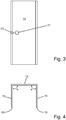
- the one in the Figures 2 and 4th entered angle ⁇ between the mounting section and the load introduction section 15 is equal to 90 ° in the illustrated embodiment. However, it can also have an angle different from 90 °, preferably in the range between 60 ° and 120 ° (not shown).
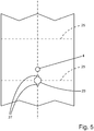
- Figure 5 shows a sheet metal blank from which a claw 11 can be produced.
- the bending lines are in the Figure 5 entered as broken lines with the reference number 25.
- the geometry of the keyhole-like opening 23 is clearly visible.
- it comprises a circle on which two elongate cutouts 27 are arranged opposite one another.
- a polygon, in particular a square, can also be selected instead of the circle.
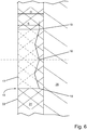
- FIG. 6 a cross section through a building wall 29 with thermal insulation 31 and assembled claw 11 is shown schematically.
- the claw 11 is in the Figure 6 from the left with their tips 19 attached to an outer surface 33 of the thermal insulation 31 and then driven into the thermal insulation 31 with hammer blows until the mounting section 13 lies flat on the outer surface 33 of the thermal insulation.
- a thickness D of the thermal insulation 31 is greater than the distance S between the mounting section 13 and the tips 19 of the load introduction sections 19.
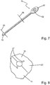
- the tie rod 76 has a connecting section 78 which can be connected to the claw 11 in a form-fitting manner and one Connection section 78 facing away from eyelet 80 with a bore 82.
- the connecting section 78 of the tie rod 76 is arrow-shaped so that it can be inserted into the mounting opening 23 with the aid of the slots 27. If it is then rotated by 90 °, a connection between the tie rod 76 and the claw 11 that can be positively loaded in tension is created.
- the tie rod 76 on the connecting section 78 has a width 84 that is smaller than the mounting opening 23 in the direction of the slots 27. Furthermore, the tie rod 76 has a width 88 at its narrowest point that is slightly smaller than the circular part of the mounting opening 23 is. This enables simple and tool-free attachment of the tie rod 76 to the facade attachment section 16.
- a keyhole-shaped opening 23 is shown enlarged. It can be clearly seen that the keyhole-shaped opening 23 is located where, starting from the sheet metal blank, the load introduction section 15 meets the mounting section 13 by bending at the angle ⁇ .
- Figure 9 shows a sheet metal blank from which the claw 11 according to the invention can be produced.
- a bending line is in the Figure 9 entered as broken lines with the reference number 25.
- the front edge 17 of the load introduction section or sections 15 according to the invention has an odd number of tips 19, in particular three tips 19, a central tip 27 extending in a plane lying in the load introduction section 15 orthogonally to the mounting section 13 than the others Tips 19.
- the middle tip 27 extends a distance 29 further than the other tips 19.
- the middle tip 27, which projects beyond the other tips 19 by the distance 29, is designed as an isosceles triangle and can therefore be used in a particularly advantageous manner be used to center the claw 11.
Landscapes
- Engineering & Computer Science (AREA)
- Architecture (AREA)
- Physics & Mathematics (AREA)
- Civil Engineering (AREA)
- Structural Engineering (AREA)
- Acoustics & Sound (AREA)
- Electromagnetism (AREA)
- Curtains And Furnishings For Windows Or Doors (AREA)
- Load-Bearing And Curtain Walls (AREA)
- Building Environments (AREA)
Claims (9)
- Patte de fixation (11) pour introduire une charge dans l'isolation thermique (31) d'un bâtiment, dans laquelle la patte de fixation (11) présente une section de montage (13) et au moins une section d'introduction de charge (15), dans laquelle la section de montage (13) et la section d'introduction de charge (15) formant un angle (α), qui est compris entre 60° et 120°, de préférence de 90°, et dans lequel un bord avant (17) de la section d'introduction de charge (15) présente au moins une pointe (19), caractérisée en ce que le bord avant (17) de la ou des sections d'introduction de charge (15) présente un nombre impair de pointes (19), en particulier trois ou cinq pointes (19), dans laquelle une pointe centrale (19) s'étend plus loin, jusque dans un plan situé dans la section d'introduction de charge (15) orthogonalement à la section de montage (13), que les autres pointes (19).
- Patte de fixation selon la revendication 1, caractérisée en ce que la patte de fixation (11) présente une section de montage (13) et deux sections d'introduction de charge (15) .
- Patte de fixation selon la revendication 2, caractérisée en ce que la patte de fixation (11) a une section transversale en forme de U ou en forme de parallélogramme.
- Patte de fixation selon l'une des revendications précédentes, caractérisée en ce que le bord avant (17) de la ou des sections d'introduction de charge (15) présente plus de trois pointes (19).
- Patte de fixation selon la revendication 1, caractérisée en ce que la pointe centrale (27) est réalisée en un triangle isocèle.
- Patte de fixation selon l'une des revendications précédentes, caractérisée en ce que la section de montage (13) présente au moins une ouverture (21), un boulon fileté et/ou un écrou.
- Patte de fixation selon l'une des revendications précédentes, caractérisée en ce qu'une ouverture en forme de trou de serrure (23) est de préférence formée sur une jonction entre une section d'introduction de charge (15) et la section de montage (13).
- Patte de fixation selon l'une des revendications précédentes, caractérisée en ce qu'il s'agit d'une pièce de tôle pliée.
- Patte de fixation selon l'une des revendications précédentes, caractérisée en ce qu'elle est constituée d'acier, notamment d'acier inoxydable, ou d'aluminium.
Priority Applications (1)
| Application Number | Priority Date | Filing Date | Title |
|---|---|---|---|
| PL16738787T PL3322860T3 (pl) | 2015-07-14 | 2016-07-14 | Łapa do wprowadzania obciążeń w izolację termiczną budynku |
Applications Claiming Priority (2)
| Application Number | Priority Date | Filing Date | Title |
|---|---|---|---|
| DE102015213173.4A DE102015213173A1 (de) | 2015-07-14 | 2015-07-14 | Klaue zur Lasteinleitung in die Wärmedämmung eines Gebäudes |
| PCT/EP2016/066732 WO2017009412A1 (fr) | 2015-07-14 | 2016-07-14 | Patte de fixation permettant l'application de charges à l'isolation thermique d'un bâtiment |
Publications (2)
| Publication Number | Publication Date |
|---|---|
| EP3322860A1 EP3322860A1 (fr) | 2018-05-23 |
| EP3322860B1 true EP3322860B1 (fr) | 2020-05-06 |
Family
ID=56411642
Family Applications (1)
| Application Number | Title | Priority Date | Filing Date |
|---|---|---|---|
| EP16738787.7A Active EP3322860B1 (fr) | 2015-07-14 | 2016-07-14 | Patte pour le transfert de charge dans l'isolation d'un bâtiment |
Country Status (4)
| Country | Link |
|---|---|
| EP (1) | EP3322860B1 (fr) |
| DE (1) | DE102015213173A1 (fr) |
| PL (1) | PL3322860T3 (fr) |
| WO (1) | WO2017009412A1 (fr) |
Families Citing this family (1)
| Publication number | Priority date | Publication date | Assignee | Title |
|---|---|---|---|---|
| CN117344783B (zh) * | 2023-11-23 | 2024-12-13 | 中国电力建设工程咨询有限公司 | 一种桩柱一体现浇钢筋混凝土储能电池预制舱单舱基础 |
Family Cites Families (10)
| Publication number | Priority date | Publication date | Assignee | Title |
|---|---|---|---|---|
| DE2513969A1 (de) * | 1974-06-15 | 1976-10-07 | Heinrich Liebig | Entlastungselement fuer anker- oder duebelbefestigungsanordnungen |
| SE446999B (sv) * | 1984-03-27 | 1986-10-20 | Sabema Material Ab | Anordning for uppberning av isolering och fasadputs |
| CA1251336A (fr) * | 1985-10-30 | 1989-03-21 | Michael A. Hatzinikolas | Armatures d'ancrage pour maconnerie |
| GB9312172D0 (en) * | 1993-06-12 | 1993-07-28 | Stone Eglinton Group Ltd | Locating device |
| AT1969U1 (de) | 1996-05-24 | 1998-02-25 | Slavonia Baubedarf Gmbh | Wandstütze für fassadenunterkonstruktionen |
| DE102005044051A1 (de) * | 2004-10-15 | 2006-05-04 | Deutsche Rockwool Mineralwoll Gmbh + Co Ohg | Gebäudedach sowie Dämmschichtaufbau und Mineralfaserdämmstoffelement für ein Gebäudedach |
| DE102006062701A1 (de) * | 2006-05-19 | 2007-12-13 | August Braun | Gebäude-Wärmedämmungsanordnung |
| JP4938512B2 (ja) * | 2007-03-15 | 2012-05-23 | ニチハ株式会社 | 下地金具および外壁施工構造 |
| WO2012143035A1 (fr) * | 2011-04-18 | 2012-10-26 | Fibrecem Holding Ag | Tôle de renforcement |
| CA2809080C (fr) * | 2012-03-14 | 2017-03-07 | Mitek Holdings, Inc. | Systeme de montage pour structures en placage |
-
2015
- 2015-07-14 DE DE102015213173.4A patent/DE102015213173A1/de not_active Withdrawn
-
2016
- 2016-07-14 PL PL16738787T patent/PL3322860T3/pl unknown
- 2016-07-14 EP EP16738787.7A patent/EP3322860B1/fr active Active
- 2016-07-14 WO PCT/EP2016/066732 patent/WO2017009412A1/fr not_active Ceased
Non-Patent Citations (1)
| Title |
|---|
| None * |
Also Published As
| Publication number | Publication date |
|---|---|
| DE102015213173A1 (de) | 2017-01-19 |
| WO2017009412A1 (fr) | 2017-01-19 |
| PL3322860T3 (pl) | 2020-10-05 |
| EP3322860A1 (fr) | 2018-05-23 |
Similar Documents
| Publication | Publication Date | Title |
|---|---|---|
| EP3081708B1 (fr) | Rail d'ancrage dans le béton | |
| EP2783437B1 (fr) | Rail support pour une armoire electrique | |
| DE202018003027U1 (de) | Verbindungsstück zur winkeligen Verbindung zweier Bauteile | |
| DE202010012937U1 (de) | Befestigungssystem | |
| DE102014106068B4 (de) | Vorrichtung zur Verbindung zweier einander gegenüberliegender plattenförmiger Schalungselemente | |
| EP1980758A2 (fr) | Elément de liaison destiné à relier deux pièces | |
| EP3322860B1 (fr) | Patte pour le transfert de charge dans l'isolation d'un bâtiment | |
| EP3568535B1 (fr) | Structures en bois avec système de liaison | |
| EP4083343B1 (fr) | Élément de fixation | |
| DE202011100168U1 (de) | Befestigungswinkel für die Unterkonstruktion von vorgehängten Fassaden und Montagesystem umfassend wenigstens einen solchen Befestigungswinkel | |
| EP2236693B1 (fr) | Support à isolation thermique pour éléments de revêtement | |
| EP2660403B1 (fr) | Support pour matière isolante | |
| DE102010018593A1 (de) | Verbindungsbeschlag | |
| EP1983138B1 (fr) | Elément de construction avec un élément de remplissage maintenu de manière étanche dans un cadre | |
| DE202011108692U1 (de) | Hohlprofil und Hallengerüst mit einem solchen Profil | |
| EP2998458B1 (fr) | Dispositif de fixation d'une plaque sur une base d'ancrage | |
| EP2447441B1 (fr) | Dispositif de fixation pour des éléments de bardage | |
| EP3339528B1 (fr) | Raccordement béton-bois et dispositif de fixation | |
| EP3910125A1 (fr) | Bâti de support permettant de suspendre au moins un absorbeur de son provenant du plafond, système d'amélioration de l'acoustique dans une pièce | |
| CH695905A5 (de) | Abstand- und Distanzhalter. | |
| DE202013104418U1 (de) | Fassadenkonsole sowie Fassadenkonstruktion | |
| EP2574202B1 (fr) | Élément de fixation | |
| AT413723B (de) | Distanzhalterkeil | |
| EP1936054B9 (fr) | Languette de traction destinée à la fixation de plaques murales en béton poreux, ainsi que système de plaques murales en béton poreux doté de languettes de traction | |
| EP0058709A1 (fr) | Boulon d'ancrage |
Legal Events
| Date | Code | Title | Description |
|---|---|---|---|
| STAA | Information on the status of an ep patent application or granted ep patent |
Free format text: STATUS: THE INTERNATIONAL PUBLICATION HAS BEEN MADE |
|
| PUAI | Public reference made under article 153(3) epc to a published international application that has entered the european phase |
Free format text: ORIGINAL CODE: 0009012 |
|
| STAA | Information on the status of an ep patent application or granted ep patent |
Free format text: STATUS: REQUEST FOR EXAMINATION WAS MADE |
|
| 17P | Request for examination filed |
Effective date: 20180110 |
|
| AK | Designated contracting states |
Kind code of ref document: A1 Designated state(s): AL AT BE BG CH CY CZ DE DK EE ES FI FR GB GR HR HU IE IS IT LI LT LU LV MC MK MT NL NO PL PT RO RS SE SI SK SM TR |
|
| AX | Request for extension of the european patent |
Extension state: BA ME |
|
| DAV | Request for validation of the european patent (deleted) | ||
| DAX | Request for extension of the european patent (deleted) | ||
| RAP1 | Party data changed (applicant data changed or rights of an application transferred) |
Owner name: EJOT AUSTRIA GMBH & CO KG |
|
| GRAP | Despatch of communication of intention to grant a patent |
Free format text: ORIGINAL CODE: EPIDOSNIGR1 |
|
| STAA | Information on the status of an ep patent application or granted ep patent |
Free format text: STATUS: GRANT OF PATENT IS INTENDED |
|
| INTG | Intention to grant announced |
Effective date: 20191204 |
|
| GRAS | Grant fee paid |
Free format text: ORIGINAL CODE: EPIDOSNIGR3 |
|
| GRAA | (expected) grant |
Free format text: ORIGINAL CODE: 0009210 |
|
| STAA | Information on the status of an ep patent application or granted ep patent |
Free format text: STATUS: THE PATENT HAS BEEN GRANTED |
|
| AK | Designated contracting states |
Kind code of ref document: B1 Designated state(s): AL AT BE BG CH CY CZ DE DK EE ES FI FR GB GR HR HU IE IS IT LI LT LU LV MC MK MT NL NO PL PT RO RS SE SI SK SM TR |
|
| REG | Reference to a national code |
Ref country code: GB Ref legal event code: FG4D Free format text: NOT ENGLISH |
|
| REG | Reference to a national code |
Ref country code: CH Ref legal event code: EP Ref country code: AT Ref legal event code: REF Ref document number: 1266943 Country of ref document: AT Kind code of ref document: T Effective date: 20200515 |
|
| REG | Reference to a national code |
Ref country code: IE Ref legal event code: FG4D Free format text: LANGUAGE OF EP DOCUMENT: GERMAN |
|
| REG | Reference to a national code |
Ref country code: DE Ref legal event code: R096 Ref document number: 502016009872 Country of ref document: DE |
|
| REG | Reference to a national code |
Ref country code: LT Ref legal event code: MG4D |
|
| REG | Reference to a national code |
Ref country code: NL Ref legal event code: MP Effective date: 20200506 |
|
| PG25 | Lapsed in a contracting state [announced via postgrant information from national office to epo] |
Ref country code: PT Free format text: LAPSE BECAUSE OF FAILURE TO SUBMIT A TRANSLATION OF THE DESCRIPTION OR TO PAY THE FEE WITHIN THE PRESCRIBED TIME-LIMIT Effective date: 20200907 Ref country code: GR Free format text: LAPSE BECAUSE OF FAILURE TO SUBMIT A TRANSLATION OF THE DESCRIPTION OR TO PAY THE FEE WITHIN THE PRESCRIBED TIME-LIMIT Effective date: 20200807 Ref country code: IS Free format text: LAPSE BECAUSE OF FAILURE TO SUBMIT A TRANSLATION OF THE DESCRIPTION OR TO PAY THE FEE WITHIN THE PRESCRIBED TIME-LIMIT Effective date: 20200906 Ref country code: SE Free format text: LAPSE BECAUSE OF FAILURE TO SUBMIT A TRANSLATION OF THE DESCRIPTION OR TO PAY THE FEE WITHIN THE PRESCRIBED TIME-LIMIT Effective date: 20200506 Ref country code: NO Free format text: LAPSE BECAUSE OF FAILURE TO SUBMIT A TRANSLATION OF THE DESCRIPTION OR TO PAY THE FEE WITHIN THE PRESCRIBED TIME-LIMIT Effective date: 20200806 Ref country code: LT Free format text: LAPSE BECAUSE OF FAILURE TO SUBMIT A TRANSLATION OF THE DESCRIPTION OR TO PAY THE FEE WITHIN THE PRESCRIBED TIME-LIMIT Effective date: 20200506 Ref country code: FI Free format text: LAPSE BECAUSE OF FAILURE TO SUBMIT A TRANSLATION OF THE DESCRIPTION OR TO PAY THE FEE WITHIN THE PRESCRIBED TIME-LIMIT Effective date: 20200506 |
|
| PG25 | Lapsed in a contracting state [announced via postgrant information from national office to epo] |
Ref country code: BG Free format text: LAPSE BECAUSE OF FAILURE TO SUBMIT A TRANSLATION OF THE DESCRIPTION OR TO PAY THE FEE WITHIN THE PRESCRIBED TIME-LIMIT Effective date: 20200806 Ref country code: LV Free format text: LAPSE BECAUSE OF FAILURE TO SUBMIT A TRANSLATION OF THE DESCRIPTION OR TO PAY THE FEE WITHIN THE PRESCRIBED TIME-LIMIT Effective date: 20200506 Ref country code: RS Free format text: LAPSE BECAUSE OF FAILURE TO SUBMIT A TRANSLATION OF THE DESCRIPTION OR TO PAY THE FEE WITHIN THE PRESCRIBED TIME-LIMIT Effective date: 20200506 Ref country code: HR Free format text: LAPSE BECAUSE OF FAILURE TO SUBMIT A TRANSLATION OF THE DESCRIPTION OR TO PAY THE FEE WITHIN THE PRESCRIBED TIME-LIMIT Effective date: 20200506 |
|
| PG25 | Lapsed in a contracting state [announced via postgrant information from national office to epo] |
Ref country code: AL Free format text: LAPSE BECAUSE OF FAILURE TO SUBMIT A TRANSLATION OF THE DESCRIPTION OR TO PAY THE FEE WITHIN THE PRESCRIBED TIME-LIMIT Effective date: 20200506 Ref country code: NL Free format text: LAPSE BECAUSE OF FAILURE TO SUBMIT A TRANSLATION OF THE DESCRIPTION OR TO PAY THE FEE WITHIN THE PRESCRIBED TIME-LIMIT Effective date: 20200506 |
|
| PG25 | Lapsed in a contracting state [announced via postgrant information from national office to epo] |
Ref country code: SM Free format text: LAPSE BECAUSE OF FAILURE TO SUBMIT A TRANSLATION OF THE DESCRIPTION OR TO PAY THE FEE WITHIN THE PRESCRIBED TIME-LIMIT Effective date: 20200506 Ref country code: EE Free format text: LAPSE BECAUSE OF FAILURE TO SUBMIT A TRANSLATION OF THE DESCRIPTION OR TO PAY THE FEE WITHIN THE PRESCRIBED TIME-LIMIT Effective date: 20200506 Ref country code: DK Free format text: LAPSE BECAUSE OF FAILURE TO SUBMIT A TRANSLATION OF THE DESCRIPTION OR TO PAY THE FEE WITHIN THE PRESCRIBED TIME-LIMIT Effective date: 20200506 Ref country code: ES Free format text: LAPSE BECAUSE OF FAILURE TO SUBMIT A TRANSLATION OF THE DESCRIPTION OR TO PAY THE FEE WITHIN THE PRESCRIBED TIME-LIMIT Effective date: 20200506 Ref country code: CZ Free format text: LAPSE BECAUSE OF FAILURE TO SUBMIT A TRANSLATION OF THE DESCRIPTION OR TO PAY THE FEE WITHIN THE PRESCRIBED TIME-LIMIT Effective date: 20200506 Ref country code: RO Free format text: LAPSE BECAUSE OF FAILURE TO SUBMIT A TRANSLATION OF THE DESCRIPTION OR TO PAY THE FEE WITHIN THE PRESCRIBED TIME-LIMIT Effective date: 20200506 |
|
| REG | Reference to a national code |
Ref country code: DE Ref legal event code: R097 Ref document number: 502016009872 Country of ref document: DE |
|
| PG25 | Lapsed in a contracting state [announced via postgrant information from national office to epo] |
Ref country code: MC Free format text: LAPSE BECAUSE OF FAILURE TO SUBMIT A TRANSLATION OF THE DESCRIPTION OR TO PAY THE FEE WITHIN THE PRESCRIBED TIME-LIMIT Effective date: 20200506 Ref country code: SK Free format text: LAPSE BECAUSE OF FAILURE TO SUBMIT A TRANSLATION OF THE DESCRIPTION OR TO PAY THE FEE WITHIN THE PRESCRIBED TIME-LIMIT Effective date: 20200506 |
|
| REG | Reference to a national code |
Ref country code: CH Ref legal event code: PL |
|
| PLBE | No opposition filed within time limit |
Free format text: ORIGINAL CODE: 0009261 |
|
| STAA | Information on the status of an ep patent application or granted ep patent |
Free format text: STATUS: NO OPPOSITION FILED WITHIN TIME LIMIT |
|
| 26N | No opposition filed |
Effective date: 20210209 |
|
| GBPC | Gb: european patent ceased through non-payment of renewal fee |
Effective date: 20200806 |
|
| REG | Reference to a national code |
Ref country code: BE Ref legal event code: MM Effective date: 20200731 |
|
| PG25 | Lapsed in a contracting state [announced via postgrant information from national office to epo] |
Ref country code: LI Free format text: LAPSE BECAUSE OF NON-PAYMENT OF DUE FEES Effective date: 20200731 Ref country code: LU Free format text: LAPSE BECAUSE OF NON-PAYMENT OF DUE FEES Effective date: 20200714 Ref country code: CH Free format text: LAPSE BECAUSE OF NON-PAYMENT OF DUE FEES Effective date: 20200731 |
|
| PG25 | Lapsed in a contracting state [announced via postgrant information from national office to epo] |
Ref country code: SI Free format text: LAPSE BECAUSE OF FAILURE TO SUBMIT A TRANSLATION OF THE DESCRIPTION OR TO PAY THE FEE WITHIN THE PRESCRIBED TIME-LIMIT Effective date: 20200506 Ref country code: BE Free format text: LAPSE BECAUSE OF NON-PAYMENT OF DUE FEES Effective date: 20200731 |
|
| PG25 | Lapsed in a contracting state [announced via postgrant information from national office to epo] |
Ref country code: IE Free format text: LAPSE BECAUSE OF NON-PAYMENT OF DUE FEES Effective date: 20200714 Ref country code: GB Free format text: LAPSE BECAUSE OF NON-PAYMENT OF DUE FEES Effective date: 20200806 |
|
| PG25 | Lapsed in a contracting state [announced via postgrant information from national office to epo] |
Ref country code: TR Free format text: LAPSE BECAUSE OF FAILURE TO SUBMIT A TRANSLATION OF THE DESCRIPTION OR TO PAY THE FEE WITHIN THE PRESCRIBED TIME-LIMIT Effective date: 20200506 Ref country code: MT Free format text: LAPSE BECAUSE OF FAILURE TO SUBMIT A TRANSLATION OF THE DESCRIPTION OR TO PAY THE FEE WITHIN THE PRESCRIBED TIME-LIMIT Effective date: 20200506 Ref country code: CY Free format text: LAPSE BECAUSE OF FAILURE TO SUBMIT A TRANSLATION OF THE DESCRIPTION OR TO PAY THE FEE WITHIN THE PRESCRIBED TIME-LIMIT Effective date: 20200506 |
|
| PG25 | Lapsed in a contracting state [announced via postgrant information from national office to epo] |
Ref country code: MK Free format text: LAPSE BECAUSE OF FAILURE TO SUBMIT A TRANSLATION OF THE DESCRIPTION OR TO PAY THE FEE WITHIN THE PRESCRIBED TIME-LIMIT Effective date: 20200506 |
|
| P01 | Opt-out of the competence of the unified patent court (upc) registered |
Effective date: 20240320 |
|
| PGFP | Annual fee paid to national office [announced via postgrant information from national office to epo] |
Ref country code: PL Payment date: 20250612 Year of fee payment: 10 |
|
| PGFP | Annual fee paid to national office [announced via postgrant information from national office to epo] |
Ref country code: DE Payment date: 20250916 Year of fee payment: 10 |
|
| PGFP | Annual fee paid to national office [announced via postgrant information from national office to epo] |
Ref country code: IT Payment date: 20250731 Year of fee payment: 10 |
|
| PGFP | Annual fee paid to national office [announced via postgrant information from national office to epo] |
Ref country code: FR Payment date: 20250723 Year of fee payment: 10 Ref country code: AT Payment date: 20250721 Year of fee payment: 10 |