EP3323276B1 - Schaltungsanordnung zum betreiben einer ersten und einer zweiten leuchteinheit eines kraftfahrzeugs - Google Patents
Schaltungsanordnung zum betreiben einer ersten und einer zweiten leuchteinheit eines kraftfahrzeugs Download PDFInfo
- Publication number
- EP3323276B1 EP3323276B1 EP16731919.3A EP16731919A EP3323276B1 EP 3323276 B1 EP3323276 B1 EP 3323276B1 EP 16731919 A EP16731919 A EP 16731919A EP 3323276 B1 EP3323276 B1 EP 3323276B1
- Authority
- EP
- European Patent Office
- Prior art keywords
- light
- emitting unit
- voltage converter
- unit
- lighting unit
- Prior art date
- Legal status (The legal status is an assumption and is not a legal conclusion. Google has not performed a legal analysis and makes no representation as to the accuracy of the status listed.)
- Active
Links
Images

Classifications
-
- B—PERFORMING OPERATIONS; TRANSPORTING
- B60—VEHICLES IN GENERAL
- B60Q—ARRANGEMENT OF SIGNALLING OR LIGHTING DEVICES, THE MOUNTING OR SUPPORTING THEREOF OR CIRCUITS THEREFOR, FOR VEHICLES IN GENERAL
- B60Q11/00—Arrangement of monitoring devices for devices provided for in groups B60Q1/00 - B60Q9/00
- B60Q11/005—Arrangement of monitoring devices for devices provided for in groups B60Q1/00 - B60Q9/00 for lighting devices, e.g. indicating if lamps are burning or not
-
- F—MECHANICAL ENGINEERING; LIGHTING; HEATING; WEAPONS; BLASTING
- F21—LIGHTING
- F21S—NON-PORTABLE LIGHTING DEVICES; SYSTEMS THEREOF; VEHICLE LIGHTING DEVICES SPECIALLY ADAPTED FOR VEHICLE EXTERIORS
- F21S41/00—Illuminating devices specially adapted for vehicle exteriors, e.g. headlamps
- F21S41/10—Illuminating devices specially adapted for vehicle exteriors, e.g. headlamps characterised by the light source
- F21S41/14—Illuminating devices specially adapted for vehicle exteriors, e.g. headlamps characterised by the light source characterised by the type of light source
- F21S41/141—Light emitting diodes [LED]
-
- H—ELECTRICITY
- H05—ELECTRIC TECHNIQUES NOT OTHERWISE PROVIDED FOR
- H05B—ELECTRIC HEATING; ELECTRIC LIGHT SOURCES NOT OTHERWISE PROVIDED FOR; CIRCUIT ARRANGEMENTS FOR ELECTRIC LIGHT SOURCES, IN GENERAL
- H05B41/00—Circuit arrangements or apparatus for igniting or operating discharge lamps
- H05B41/14—Circuit arrangements
- H05B41/36—Controlling
- H05B41/38—Controlling the intensity of light
-
- H—ELECTRICITY
- H05—ELECTRIC TECHNIQUES NOT OTHERWISE PROVIDED FOR
- H05B—ELECTRIC HEATING; ELECTRIC LIGHT SOURCES NOT OTHERWISE PROVIDED FOR; CIRCUIT ARRANGEMENTS FOR ELECTRIC LIGHT SOURCES, IN GENERAL
- H05B47/00—Circuit arrangements for operating light sources in general, i.e. where the type of light source is not relevant
- H05B47/20—Responsive to malfunctions or to light source life; for protection
-
- B—PERFORMING OPERATIONS; TRANSPORTING
- B60—VEHICLES IN GENERAL
- B60Q—ARRANGEMENT OF SIGNALLING OR LIGHTING DEVICES, THE MOUNTING OR SUPPORTING THEREOF OR CIRCUITS THEREFOR, FOR VEHICLES IN GENERAL
- B60Q2300/00—Indexing codes for automatically adjustable headlamps or automatically dimmable headlamps
- B60Q2300/10—Indexing codes relating to particular vehicle conditions
- B60Q2300/14—Other vehicle conditions
- B60Q2300/146—Abnormalities, e.g. fail-safe
-
- H—ELECTRICITY
- H05—ELECTRIC TECHNIQUES NOT OTHERWISE PROVIDED FOR
- H05B—ELECTRIC HEATING; ELECTRIC LIGHT SOURCES NOT OTHERWISE PROVIDED FOR; CIRCUIT ARRANGEMENTS FOR ELECTRIC LIGHT SOURCES, IN GENERAL
- H05B47/00—Circuit arrangements for operating light sources in general, i.e. where the type of light source is not relevant
- H05B47/10—Controlling the light source
Definitions
- the invention relates to a lighting arrangement comprising a light module of a motor vehicle and a circuit arrangement.
- EN 10 2011 005 582 A1 discloses a lighting arrangement according to the preamble of claim 1.
- the lighting device is provided for a motor vehicle with a light source which is designed to generate light from supplied electrical energy.
- a control circuit is designed to control an electrical current flow through the light source by actuating a switching element coupled to the light source.
- EN 10 2013 113 007 A1 discloses a control device for external lighting units of vehicles.
- this control device the control of a neighboring control unit, if it cannot be operated properly, is carried out via a single line.
- the two front headlight units of the vehicle provide each other with so-called emergency lighting for the adjacent headlight unit via just one cable if the power supply for one of the two headlight units fails.
- EN 100 44 194 A1 discloses a discharge lamp device for vehicles.
- EP 1 379 108 A1 reveals an LED supply and identification unit.
- a light module which comprises several semiconductor light sources arranged in a matrix.
- each lighting unit of a motor vehicle headlight is assigned a respective voltage converter. Accordingly, the failure of an individual voltage converter leads to the failure of the lighting function of the corresponding lighting unit.
- the object of the invention is to prevent a failure of a lighting function.
- the second voltage converter is configured with an operating parameter for the first lighting unit, in particular an output voltage of the voltage converter, before the second voltage converter is connected to the first lighting unit.
- This configuration can advantageously be used to adapt the second voltage converter to the first lighting unit.
- a lighting device for a motor vehicle is designated in its entirety with the reference number 1.
- the lighting device 1 is designed as a motor vehicle headlight.
- the headlight 1 comprises a housing 2 which is closed by a transparent cover plate 4. In a light exit direction 3, the headlight housing 2 has a light exit opening.
- the headlight 1 comprises two light units 5 and 6, which produce a desired light distribution either alone or in combination with one another.
- the light units 5 and 6 can, for example, be used as reflection modules, projection modules or together to form a light module.
- a control unit 7 is arranged on the outside of the headlight housing 2.
- the control unit 7 can also be an integral part of the lighting units 5 and 6.
- the lighting units 5 and 6 are controlled by the control unit 7 via connecting lines 8, which are Figure 1 are symbolically represented by a dashed line.
- the lighting units 5, 6 are supplied with electrical energy via the cables 8.
- the lighting units 5, 6 each use one or more semiconductor light sources, in particular light-emitting diodes, as light sources.
- Headlights 1 that have a large number of light-emitting diodes are referred to as pixel or matrix headlights.
- parts, in particular a single or multiple light-emitting diodes are dimmed or switched on or off in order to achieve different light distributions.
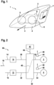
- FIG. 2 shows a schematic block diagram, which is referred to in its entirety as circuit arrangement 60.
- a first voltage converter 10 is provided for operating the first lighting unit 5.
- a second voltage converter 12 is provided for operating the second lighting unit 6.
- the voltage converters 10 and 12 are each connected to the vehicle electrical system 18 via lines 14 and 16. Alternatively, the Voltage converters 10 and 12 can also be connected to an intermediate voltage and thus to other components in the direction of the on-board network 18.
- On output lines 20 and 22, the voltage converters 10 and 12 generate a voltage level that is different from the input and can be fed to the respective lighting units 5 and 6.
- the output lines 20 and 22 are connected to a switching unit 30, which in normal operation connects the line 20 to a line 32 for operating the lighting unit 5 and connects the line 22 to a line 34 for operating the lighting unit 6.
- the switching unit 30 opens the connection between the lines 20 and 32 and the connection between the lines 22 and 34 and connects the lines 22 and 32 according to a connection path 40 in order to continue operating the lighting unit 5.
- the lighting unit 6 is thereby de-energized.
- the trigger signal 36 is generated by a monitoring unit 42, which detects an error in the area of the voltage converter 10 and/or in the area of the lighting unit 5. In particular, errors in the area of the voltage converter 10 do not lead to the failure of the lighting unit 5 by triggering the connection path 40.
- the sensor signals 46 and 50 are sent to the monitoring unit 42.
- the monitoring unit 42 can carry out a relative comparison of the sensor signals 46 and 50. Furthermore, a comparison of the respective sensor signals 46 and 50 with a corresponding target value can be carried out.
- the trigger signal 36 is determined depending on the evaluation of the sensor signals 46 and 50 or one of the sensor signals 46 and 50.
- the arrangement of the sensors 44 and 48 between the switching unit 30 and the respective lighting unit 5 or 6 makes it easier to distinguish between a malfunction of the lighting unit 5 or 6 and another unit in the direction of the on-board network 18.
- the lighting unit 5 is designed to generate a low beam distribution and the lighting unit 6 is designed to generate a high beam distribution
- a defect can be detected and the path 40 activated by determining a reduction in voltage below a predetermined threshold value on the line 32 using the sensor 44. If the subordinate lighting unit 6 is not active at the time of the defect detection, the voltage converter 10 is deactivated and the voltage converter 12 is activated to operate the lighting unit 5, i.e. switched to operate the lighting unit 5. If the subordinate lighting unit 6 is switched on at the time of the defect detection, it is switched off and the voltage converter 12 is switched to operate the lighting unit 5. The lighting unit 5 is then switched on and an error message is brought to the attention of the driver of the vehicle.
- the voltage converter 12 which is intended for operating the high beam in the sense of the lighting unit 6 in normal operation, thus functions as a reserve for the voltage converter 10 of the low beam 5. Therefore, if the voltage converter 10 fails, the high beam is no longer available, but this is tolerated by maintaining a safe driving condition by means of the active low beam function.
- Figure 3 shows a block diagram of a further embodiment of the circuit arrangement 60.
- a schematic view opposite to the direction of radiation shows how the lighting unit 5 is arranged within the lighting unit 6.
- the lighting unit 5 is assigned a higher operating priority than the lighting unit 6, since the light distribution generated centrally by the lighting unit 5 has a higher operating priority.
- the converter 12 can be used to operate the lighting unit 5 according to the connection path 40.
- the lighting unit 6 is then de-energized.
- the connection paths 52 and 54 are used for normal operation of the headlight.
- the center of a matrix headlight in the form of the lighting unit 5 is more important for the light distribution generated than the edge of the matrix headlight in the form of the lighting unit 6.
Landscapes
- Engineering & Computer Science (AREA)
- Mechanical Engineering (AREA)
- Physics & Mathematics (AREA)
- Microelectronics & Electronic Packaging (AREA)
- Optics & Photonics (AREA)
- General Engineering & Computer Science (AREA)
- Lighting Device Outwards From Vehicle And Optical Signal (AREA)
Description
- Die Erfindung betrifft eine Beleuchtungsanordnung umfassend Lichtmodul eines Kraftfahrzeugs und eine Schaltungsanordnung.
-
DE 10 2011 005 582 A1 offenbart eine Beleuchtungsanordnung gemäß dem Oberbegriff von Anspruch 1. Die Beleuchtungseinrichtung ist für ein Kraftfahrzeug mit einer Lichtquelle vorgesehen, die dazu eingerichtet ist, aus zugeführter elektrischer Energie Licht zu erzeugen. Eine Ansteuerschaltung ist dazu eingerichtet, einen elektrischen Stromfluss durch die Lichtquelle durch eine Betätigung eines mit der Lichtquelle gekoppelten Schaltelements zu steuern. -
DE 10 2013 113 007 A1 offenbart eine Steuereinrichtung für Außenlichteinheiten von Fahrzeugen. Bei dieser Steuereinrichtung erfolgt die Ansteuerung einer benachbarten Steuereinheit, falls diese nicht ordnungsgemäß betrieben werden kann, über eine einzelne Leitung. Die beiden vorderen Frontlichteinheiten des Fahrzeugs stellen gegenseitig über nur eine Leitung eine sogenannte Notbeleuchtung für die jeweils benachbarte Frontlichteinheit bereit, wenn die Stromversorgung für eine der beiden Frontlichteinheiten ausfällt. -
DE 100 44 194 A1 offenbart eine Entladungslampenvorrichtung für Fahrzeuge. -
EP 1 379 108 A1 offenbart eine LED Versorgungs- und Identifikationseinheit. - Aus der
DE 101 09 024 B4 ist ein getakteter Spannungswandler bekannt. - Aus der
DE 10 2010 050 851 A1 ist bekannt, dass DC-DC-Wandler aus einer Bordnetzspannung eine Betriebsspannung für Halbleiterlichtquellen erzeugen. - Aus der
DE 10 2009 053 581 B3 ist ein Lichtmodul bekannt, das mehrere matrixartig angeordnete Halbleiterlichtquellen umfasst. - Des Weiteren ist bekannt, dass jeder Leuchteinheit eines Kraftfahrzeugscheinwerfers ein jeweiliger Spannungswandler zugeordnet ist. Entsprechend führt ein Ausfall eines einzelnen Spannungswandlers zum Ausfall der Leuchtfunktion der entsprechenden Leuchteinheit.
- Es können mehrere Spannungswandler mit ähnlichen Eigenschaften für einen Scheinwerfer vorgesehen sein. Bestimmte Lichtverhältnisse, wie beispielsweise durch Abblendlicht erzeugt, sind für ein sicheres Fahren notwendig, wohingegen andere Funktionen wie Fernlicht nur zeitweilig eingeschaltet sind.
- Mithin ist es Aufgabe der Erfindung, einen Ausfall einer Leuchtfunktion zu verhindern.
- Das der Erfindung zugrunde liegende Problem wird durch eine Beleuchtungsanordnung gelöst, die im Anspruch 1 definiert ist. Vorteilhafte Weiterbildungen sind in den Unteransprüchen angegeben. Für die Erfindung wichtige Merkmale finden sich ferner in der nachfolgenden Beschreibung und in den Zeichnungen, wobei die Merkmale sowohl in Alleinstellung als auch in unterschiedlichen Kombinationen für die Erfindung wichtig sein können, ohne dass hierauf nochmals explizit hingewiesen wird.
- Mittels einer zwischen Leuchteinheiten und Spannungswandlern angeordneten Schalteinheit wird ein zweiter Spannungswandler mit einer ersten Leuchteinheit verbunden. Vorteilhaft kann dadurch die erste Leuchteinheit auch bei Ausfall eines zugehörigen ersten Spannungswandlers weiter betrieben werden, was die Verkehrssicherheit und Fahrbereitschaft des Kraftfahrzeugs erhöht.
- Es wird ein Fehler bezüglich des ersten Spannungswandlers und/oder bezüglich der ersten Leuchteinheit ermittelt und in Abhängigkeit von dem ermittelten Fehler wird der zweite Spannungswandler mit der ersten Leuchteinheit verbunden. Vorteilhaft kann damit auch bei Auftreten eines Fehlers eine Energieversorgung der ersten Leuchteinheit sichergestellt werden.
- Der ersten Leuchteinheit wird eine höhere Betriebspriorität zugeordnet als der zweiten Leuchteinheit. Die zweite Leuchteinheit wird stromlos geschaltet. Mithin kann bei Ausfall eines Spannungswandlers, der einer Leuchteinheit zugeordnet ist, die eine höhere Betriebspriorität als eine andere Leuchteinheit aufweist, beispielsweise ein Abblendlicht bei Ausfall des entsprechenden Spannungswandlers mit einem Spannungswandler eines Fernlichts weiter betrieben werden.
- In einer vorteilhaften Ausführungsform wird ein Sensorsignal, insbesondere ein Strom oder eine Spannung, zwischen den ersten Spannungswandler und der ersten Leuchteinheit ermittelt. Der Fehler wird in Abhängigkeit von dem Sensorsignal ermittelt. Durch die Anordnung des entsprechenden Sensors zwischen dem ersten Spannungswandler und der ersten Leuchteinheit kann beispielsweise durch einen Soll-Ist-Wert-Vergleich zum einen festgestellt werden, ob der Spannungswandler korrekt funktioniert und zum anderen kann festgestellt werden, ob die Leuchteinheit korrekt funktioniert.
- In einer vorteilhaften Ausführungsform wird der zweite Spannungswandler vor der Verbindung des zweiten Spannungswandlers mit der ersten Leuchteinheit mit einem Betriebsparameter für die erste Leuchteinheit, insbesondere einer Ausgangsspannung des Spannungswandlers, konfiguriert. Vorteilhaft kann durch diese Konfiguration eine Anpassung des zweiten Spannungswandlers an die erste Leuchteinheit erfolgen.
- Weitere Merkmale, Anwendungsmöglichkeiten und Vorteile der Erfindung ergeben sich aus der nachfolgenden Beschreibung von Ausführungsbeispielen der Erfindung, die in den Figuren der Zeichnung dargestellt sind. Hierbei bilden alle beschriebenen oder dargestellten Merkmale für sich oder in beliebiger Kombination den Gegenstand der Erfindung, unabhängig von ihrer Zusammenfassung in den Patentansprüchen oder deren Rückbeziehung sowie unabhängig von ihrer Formulierung bzw. Darstellung in der Beschreibung bzw. in der Zeichnung. Für funktionsäquivalente Größen und Merkmale werden in allen Figuren auch bei unterschiedlichen Ausführungsformen die gleichen Bezugszeichen verwendet.
- Nachfolgend werden beispielhafte Ausführungsformen der Erfindung unter Bezugnahme auf die Zeichnung erläutert. In der Zeichnung zeigen:
- Figur 1
- eine Beleuchtungseinrichtung für ein Kraftfahrzeug;
- Figuren 2 und 3
- schematische Blockdiagramme.
- In
Figur 1 ist eine Beleuchtungseinrichtung für ein Kraftfahrzeug in ihrer Gesamtheit mit dem Bezugszeichen 1 bezeichnet. Die Beleuchtungseinrichtung 1 ist als Kraftfahrzeugscheinwerfer ausbildet. Der Scheinwerfer 1 umfasst ein Gehäuse 2, welches durch eine transparente Abdeckscheibe 4 verschlossen ist. In einer Lichtaustrittsrichtung 3 weist das Scheinwerfergehäuse 2 eine Lichtaustrittsöffnung auf. - Der Scheinwerfer 1 umfasst zwei Leuchteinheiten 5 und 6, die entweder alleine oder in Kombination miteinander eine gewünschte Lichtverteilung erzeugen. Die Leuchteinheiten 5 und 6 können beispielsweise als Reflexionsmodule, Projektionsmodule oder aber gemeinsam ein Lichtmodul bilden.
- An der Außenseite des Scheinwerfergehäuses 2 ist ein Steuergerät 7 angeordnet. Alternativ kann das Steuergerät 7 auch integraler Bestandteil der Leuchteinheiten 5 und 6 sein. Die Ansteuerung der Leuchteinheiten 5 und 6 durch das Steuergerät 7 erfolgt über Verbindungsleitungen 8, die in
Figur 1 durch eine gestrichelte Linie symbolisch dargestellt sind. Über die Leitungen 8 erfolgt eine Versorgung der Leuchteinheiten 5, 6 mit elektrischer Energie. - Die Leuchteinheiten 5, 6 nutzen als Lichtquellen jeweils eine oder mehrere Halbleiterlichtquellen, insbesondere Leuchtdioden. Scheinwerfer 1, die eine Vielzahl von Leuchtdioden aufweisen, werden als Pixel- oder Matrixscheinwerfer bezeichnet. Bei diesen Matrixscheinwerfern werden Teile, insbesondere eine einzige oder mehrere Leuchtdioden, gedimmt oder ein-, bzw. ausgeschaltet, um unterschiedliche Lichtverteilungen zu erreichen. Bei diesen Matrixscheinwerfern ist es nun möglich einen ersten Teil der Leuchtdioden der Leuchteinheit 5 zuzuordnen und einen zweiten Teil der Leuchtdioden der Leuchteinheit 6 zuzuordnen.
- Beispielsweise ist die Leuchteinheit 5 zur Erzeugung eines Abblendlichts und/oder zur Erzeugung eines Positionslichts vorgesehen. Die Leuchteinheit 6 ist zur Erzeugung eines Tagfahrlichts, Fernlichts oder einer sonstigen Lichtverteilung vorgesehen. In diesem Beispiel hat die erste Leuchteinheit 5 aufgrund ihrer Sicherheitsfunktion für die Erzeugung vorrangiger Lichtverteilungen eine höhere Betriebspriorität im Vergleich zur Leuchteinheit 6.
-
Figur 2 zeigt ein schematisches Blockdiagramm, das in seiner Gesamtheit als Schaltungsanordnung 60 bezeichnet wird. Ein erster Spannungswandler 10 ist zu einem Betrieb der ersten Leuchteinheit 5 vorgesehen. Ein zweiter Spannungswandler 12 ist zum Betrieb der zweiten Leuchteinheit 6 vorgesehen. Über Leitungen 14 und 16 sind die Spannungswandler 10 und 12 jeweils an das Bordnetz 18 des Kraftfahrzeugs angeschlossen. Alternativ können die Spannungswandler 10 und 12 auch an eine Zwischenspannung und damit an weitere Komponenten in Richtung des Bordnetzes 18 angeschlossen sein. Auf Ausgangsleitungen 20 und 22 erzeugen die Spannungswandler 10 und 12 ein vom Eingang unterschiedliches Spannungsniveau, das den jeweiligen Leuchteinheiten 5 und 6 zuführbar ist. Die Ausgangsleitungen 20 und 22 sind an eine Schalteinheit 30 angeschlossen, die im Normalbetrieb die Leitung 20 mit einer Leitung 32 zum Betrieb der Leuchteinheit 5 verbindet und die Leitung 22 mit einer Leitung 34 zum Betrieb der Leuchteinheit 6 verbindet. - Bei Empfang eines Auslösesignals 36 öffnet die Schalteinheit 30 die Verbindung zwischen den Leitungen 20 und 32 und die Verbindung zwischen den Leitungen 22 und 34 und verbindet die Leitungen 22 und 32 gemäß einem Verbindungspfad 40, um die Leuchteinheit 5 weiter zu betreiben. Die Leuchteinheit 6 wird hierbei stromlos geschaltet. Das Auslösesignal 36 wird von einer Überwachungseinheit 42 erzeugt, die einen Fehler im Bereich des Spannungswandlers 10 und/oder im Bereich der Leuchteinheit 5 feststellt. Insbesondere führen vorteilhaft Fehler im Bereich des Spannungswandlers 10 durch Auslösen des Verbindungspfades 40 nicht zum Ausfall der Leuchteinheit 5.
- Der Leitung 32 ist ein Sensor 44 zur Ermittlung eines Sensorsignals 46 zugeordnet. Das Sensorsignal 46 kann einen Strom oder eine Spannung bezüglich der Leitung 32 umfassen. Der Leitung 34 ist ein Sensor 48 zur Ermittlung eines Sensorsignals 50 zugeordnet, wobei es sich bei dem Sensorsignal 50 um einen Strom und/oder eine Spannung bezüglich der Leitung 34 handelt.
- Die Sensorsignale 46 und 50 werden der Überwachungseinheit 42 zugeführt. Die Überwachungseinheit 42 kann einen relativen Vergleich der Sensorsignale 46 und 50 durchführen. Des Weiteren kann ein Vergleich der jeweiligen Sensorsignale 46 und 50 mit einem entsprechenden Soll-Wert erfolgen. In Abhängigkeit von der Auswertung der Sensorsignale 46 und 50 bzw. eines der Sensorsignale 46 und 50 wird das Auslösesignal 36 ermittelt. Durch die Anordnung der Sensoren 44 bzw. 48 zwischen der Schalteinheit 30 und der jeweiligen Leuchteinheit 5 bzw. 6 kann vorteilhaft besser zwischen einer Fehlfunktion der Leuchteinheit 5 bzw. 6 und einer weiteren Einheit in Richtung des Bordnetzes 18 unterschieden werden.
- Ist beispielsweise die Leuchteinheit 5 zur Erzeugung einer Abblendlichtverteilung ausgebildet und ist die Leuchteinheit 6 zur Erzeugung einer Fernlichtverteilung ausgebildet, so kann durch eine Ermittlung einer Verringerung einer Spannung unter einen vorbestimmten Schwellwert auf der Leitung 32 mittels des Sensors 44 ein Defekt erkannt werden und der Pfad 40 aktiviert werden. Ist die nachrangige Leuchteinheit 6 zum Zeitpunkt der Defekterkennung nicht aktiv, dann wird der Spannungswandler 10 deaktiviert und der Spannungswandler 12 zum Betrieb der Leuchteinheit 5 aktiviert, d.h. zum Betrieb der Leuchteinheit 5 umgeschaltet. Ist die nachrangige Leuchteinheit 6 zum Zeitpunkt der Defekterkennung eingeschaltet, so wird diese abgeschaltet und der Spannungswandler 12 zum Betrieb der Leuchteinheit 5 umgeschaltet. Anschließend wird die Leuchteinheit 5 eingeschaltet und eine Fehlermeldung wird dem Fahrer des Fahrzeugs zur Kenntnis gebracht. Zur Erkennung des Spannungsabfalls auf der Leitung 32 muss eine Überwachung der Leitung 34 nicht zwingend erfolgen, womit auch bei ausgeschaltetem Fernlicht gemäß der Leuchteinheit 6 der Betrieb der Leuchteinheit 5 sicher aufrechterhalten werden kann. Damit fungiert der Spannungswandler 12, der im Normalbetrieb zum Betrieb des Fernlichts im Sinne der Leuchteinheit 6 vorgesehen ist als Reserve für den Spannungswandler 10 des Abblendlichts 5. Mithin steht bei einem Ausfall des Spannungswandlers 10 kein Fernlicht mehr zur Verfügung, was aber durch das Aufrechterhalten eines sicheren Fahrzustands mittels der aktiven Abblendlichtfunktion toleriert wird.
- Selbstverständlich sind noch weitere Beispiele für zwei unterschiedlich priorisierte Leuchteinheiten 5 und 6 denkbar. Im Falle von Matrixscheinwerfern können beispielsweise bestimmte Bereiche und/oder aber bestimmte Leuchtdioden den unterschiedlichen Leuchteinheiten 5, 6 und damit unterschiedlichen Spannungswandlern 10, 12 zugeordnet werden.
-
Figur 3 zeigt ein Blockschaltbild in einer weiteren Ausführungsform der Schaltungsanordnung 60. Beispielhaft ist in einer schematischen Sicht entgegen der Abstrahlrichtung gezeigt wie die Leuchteinheit 5 innerhalb der Leuchteinheit 6 angeordnet ist. Der Leuchteinheit 5 ist eine höhere Betriebspriorität zugeordnet als der Leuchteinheit 6, da die zentral durch die Leuchteinheit 5 erzeugte Lichtverteilung eine höhere Betriebspriorität besitzt. Durch die hier vorgestellte Schaltungsanordnung 60 kann bei einem Ausfall im Zentrum des Scheinwerfers, d.h. im Bereich der Leuchteinheit 5, der Wandler 12 gemäß dem Verbindungspfad 40 zum Betrieb der Leuchteinheit 5 verwendet werden. Die Leuchteinheit 6 wird hierbei stromlos geschaltet. Die Verbindungspfade 52 und 54 dienen zum Normalbetrieb des Scheinwerfers. Insbesondere ist das Zentrum eines Matrixscheinwerfers in Form der Leuchteinheit 5 wichtiger für die erzeugte Lichtverteilung wie der Rand des Matrixscheinwerfers in Form der Leuchteinheit 6.
Claims (3)
- Beleuchtungsanordnung umfassend:- ein Lichtmodul eines Kraftfahrzeugs, umfassend eine erste Leuchteinheit (5) und eine zweite Leuchteinheit (6) und- eine Schaltungsanordnung (60) zum Betreiben der ersten und der zweiten Leuchteinheit (5, 6) des Lichtmoduls,wobei jede der ersten und zweiten Leuchteinheiten (5, 6) als Lichtquellen jeweils eine oder mehrere Leuchtdioden aufweisen,dadurch gekennzeichnet, dassdie Schaltungsanordnung (60)- einen ersten Spannungswandler (10) zu einem Betrieb der ersten Leuchteinheit (5),- einen zweiten Spannungswandler (12) zum Betrieb der zweiten Leuchteinheit (6),- eine Schalteinheit (30) und- eine Überwachungseinheit (42)aufweist,dass die Schalteinheit (30) zwischen der ersten und zweiten Leuchteinheit (5, 6) und dem ersten und zweiten Spannungswandler (10, 12) angeordnet ist,dass im Normalbetrieb mittels der Schalteinheit (30) die erste Leuchteinheit (5) mit dem ersten Spannungswandler (12) und die zweite Leuchteinheit (6) mit dem zweiten Spannungswandler (12) verbindbar ist,dass die Schalteinheit (30) dazu ausgelegt ist, nach Erhalt eines Auslösesignals (36) erzeugt von der Überwachungseinheit (42), welche einen Fehler bezüglich des ersten Spannungswandlers (12) ermittelt, den zweiten Spannungswandler (12) mit der ersten Leuchteinheit (5) zu verbinden und die zweite Leuchteinheit (6) stromlos zu schalten, dass der ersten Leuchteinheit (5) eine höhere Betriebspriorität zugeordnet ist als der zweiten Leuchteinheit (6).
- Beleuchtungsanordnung nach Anspruch 1, dadurch gekennzeichnet, dass die Schaltungsanordnung (60) einen Sensor (44) aufweist, der einer Leitung (32) der Beleuchtungseinrichtung, welche die erste Leuchteinheit (5) mit der Schalteinheit (30) verbindet, zugeordnet ist, wobei der Sensor (44) zur Ermittlung eines Sensorsignals eingerichtet ist,wobei das Sensorsignal einen Strom oder eine Spannung der Leitung (32) zwischen dem ersten Spannungswandler (10) und der ersten Leuchteinheit (5) umfasst,wobei das Sensorsignal (46) der Überwachungseinheit (42) zugeführt ist, undwobei die Überwachungseinheit (42) eingerichtet ist, das Auslösesignal in Abhängigkeit von dem zugeführten Sensorsignal (46) zu ermitteln.
- Beleuchtungsanordnung nach dem Anspruch 2, dadurch gekennzeichnet, dass der zweite Spannungswandler (12) mit einem Betriebsparameter der ersten Leuchteinheit (5), welcher eine Ausgangsspannung des ersten Spannungswandlers (10) ist, konfigurierbar ist.
Applications Claiming Priority (2)
| Application Number | Priority Date | Filing Date | Title |
|---|---|---|---|
| DE102015213291.9A DE102015213291A1 (de) | 2015-07-15 | 2015-07-15 | Verfahren zum Betreiben einer ersten und einer zweiten Leuchteinheit eines Kraftfahrzeugs und Schaltungsanordnung |
| PCT/EP2016/064716 WO2017009023A1 (de) | 2015-07-15 | 2016-06-24 | Verfahren zum betreiben einer ersten und einer zweiten leuchteinheit eines kraftfahrzeugs und schaltungsanordnung |
Publications (2)
| Publication Number | Publication Date |
|---|---|
| EP3323276A1 EP3323276A1 (de) | 2018-05-23 |
| EP3323276B1 true EP3323276B1 (de) | 2024-08-21 |
Family
ID=56203405
Family Applications (1)
| Application Number | Title | Priority Date | Filing Date |
|---|---|---|---|
| EP16731919.3A Active EP3323276B1 (de) | 2015-07-15 | 2016-06-24 | Schaltungsanordnung zum betreiben einer ersten und einer zweiten leuchteinheit eines kraftfahrzeugs |
Country Status (4)
| Country | Link |
|---|---|
| US (1) | US10292248B2 (de) |
| EP (1) | EP3323276B1 (de) |
| DE (1) | DE102015213291A1 (de) |
| WO (1) | WO2017009023A1 (de) |
Families Citing this family (4)
| Publication number | Priority date | Publication date | Assignee | Title |
|---|---|---|---|---|
| FR3083418A1 (fr) * | 2018-06-28 | 2020-01-03 | Valeo Vision | Systeme de pilotage de l'alimentation electrique d'une source lumineuse pixellisee |
| FR3086900B1 (fr) * | 2018-10-04 | 2022-09-09 | Renault Sas | Projecteur pour vehicule automobile |
| JP7505357B2 (ja) * | 2020-09-30 | 2024-06-25 | 市光工業株式会社 | 車両用灯具システム及び車両用灯具 |
| JP7521363B2 (ja) * | 2020-09-30 | 2024-07-24 | 市光工業株式会社 | 車両用灯具システム |
Citations (3)
| Publication number | Priority date | Publication date | Assignee | Title |
|---|---|---|---|---|
| DE10044194A1 (de) * | 1999-09-10 | 2001-03-22 | Koito Mfg Co Ltd | Entladungslampenvorrichtung für Fahrzeuge |
| EP1379108A1 (de) * | 2002-07-04 | 2004-01-07 | Patent-Treuhand-Gesellschaft für elektrische Glühlampen mbH | LED Versorgungs- und Identifikationseinheit |
| DE102013113007A1 (de) * | 2013-11-25 | 2015-05-28 | Lear Corporation Gmbh | Steuereinrichtung für Außenlichteinheiten von Fahrzeugen |
Family Cites Families (18)
| Publication number | Priority date | Publication date | Assignee | Title |
|---|---|---|---|---|
| FR2656477B1 (fr) * | 1989-12-27 | 1992-08-28 | Sagem | Dispositif de commande d'une charge en remplacement d'une charge defaillante. |
| US5680098A (en) | 1995-09-27 | 1997-10-21 | Ford Motor Company | Circuit for compensating for failure of a light source in an automotive vehicle |
| DE10041888A1 (de) * | 2000-08-25 | 2002-03-07 | Hella Kg Hueck & Co | Steuergerät für ein Fahrzeug |
| DE10109024B4 (de) | 2001-02-24 | 2012-02-02 | Automotive Lighting Reutlingen Gmbh | Spannungswandler |
| DE102005055009A1 (de) * | 2005-11-18 | 2007-05-31 | Daimlerchrysler Ag | Vorrichtung zum Steuern eines Beleuchtungssystems in einem Fahrzeug |
| US8427063B2 (en) | 2009-07-29 | 2013-04-23 | Vektrex Electronic Systems, Inc. | Multicolor LED sequencer |
| DE102009053581B3 (de) | 2009-10-05 | 2011-03-03 | Automotive Lighting Reutlingen Gmbh | Lichtmodul für eine Beleuchtungseinrichtung eines Kraftfahrzeugs |
| US8471486B2 (en) * | 2010-04-21 | 2013-06-25 | Taiwan Semiconductor Manufacturing Company, Ltd. | Energy-saving mechanisms in multi-color display devices |
| CN102347601B (zh) * | 2010-08-04 | 2014-01-22 | 鸿富锦精密工业(深圳)有限公司 | 电源保护电路 |
| DE102010050581A1 (de) | 2010-11-05 | 2012-05-10 | Epcos Ag | Chip mit vier mit akustischen Oberflächenwellen arbeitenden Filtern |
| DE102010050851A1 (de) | 2010-11-09 | 2012-05-10 | Automotive Lighting Reutlingen Gmbh | Verfahren zum Steuern der Helligkeit von Halbleiterlichtquellen eines Kraftfahrzeug und korrespondierende Vorrichtungen |
| DE102011005582A1 (de) * | 2011-03-15 | 2012-09-20 | Automotive Lighting Reutlingen Gmbh | Beleuchtungseinrichtung für ein Kraftfahrzeug mit einer redundanten Ansteuerung von Lichtquellen |
| CN102752902B (zh) * | 2011-04-22 | 2014-10-15 | 登丰微电子股份有限公司 | 发光二极管驱动电路 |
| US9060400B2 (en) * | 2011-07-12 | 2015-06-16 | Arkalumen Inc. | Control apparatus incorporating a voltage converter for controlling lighting apparatus |
| DE102012202290B4 (de) * | 2012-02-15 | 2014-03-27 | Automotive Lighting Reutlingen Gmbh | Lichtmodul für ein blendungsfreies Kraftfahrzeug-Fernlicht |
| DE102013201766A1 (de) | 2013-02-04 | 2014-08-07 | Osram Gmbh | Beleuchtungseinrichtung und Verfahren zum Betreiben einer Beleuchtungseinrichtung |
| JP6688226B2 (ja) * | 2014-12-03 | 2020-04-28 | 株式会社小糸製作所 | 車両用灯具およびその光源の異常検出器 |
| US9974128B2 (en) * | 2014-12-24 | 2018-05-15 | Koito Manufacturing Co., Ltd. | Light source lighting circuit and turn signal lamp |
-
2015
- 2015-07-15 DE DE102015213291.9A patent/DE102015213291A1/de not_active Ceased
-
2016
- 2016-06-24 US US15/744,931 patent/US10292248B2/en active Active
- 2016-06-24 WO PCT/EP2016/064716 patent/WO2017009023A1/de not_active Ceased
- 2016-06-24 EP EP16731919.3A patent/EP3323276B1/de active Active
Patent Citations (3)
| Publication number | Priority date | Publication date | Assignee | Title |
|---|---|---|---|---|
| DE10044194A1 (de) * | 1999-09-10 | 2001-03-22 | Koito Mfg Co Ltd | Entladungslampenvorrichtung für Fahrzeuge |
| EP1379108A1 (de) * | 2002-07-04 | 2004-01-07 | Patent-Treuhand-Gesellschaft für elektrische Glühlampen mbH | LED Versorgungs- und Identifikationseinheit |
| DE102013113007A1 (de) * | 2013-11-25 | 2015-05-28 | Lear Corporation Gmbh | Steuereinrichtung für Außenlichteinheiten von Fahrzeugen |
Also Published As
| Publication number | Publication date |
|---|---|
| WO2017009023A1 (de) | 2017-01-19 |
| US10292248B2 (en) | 2019-05-14 |
| EP3323276A1 (de) | 2018-05-23 |
| US20180270937A1 (en) | 2018-09-20 |
| DE102015213291A1 (de) | 2017-01-19 |
Similar Documents
| Publication | Publication Date | Title |
|---|---|---|
| DE102015201739B4 (de) | Fahrzeugleuchte | |
| DE102006015053B4 (de) | LED-Blinker und Fehlerdetektionsverfahren | |
| EP2501206B1 (de) | Beleuchtungseinrichtung für ein Kraftfahrzeug mit einer redundanten Ansteuerung von Lichtquellen | |
| EP3323276B1 (de) | Schaltungsanordnung zum betreiben einer ersten und einer zweiten leuchteinheit eines kraftfahrzeugs | |
| EP2390140B1 (de) | Schaltungsanordnung | |
| WO2001030119A1 (de) | Ansteuerschaltung für led und zugehöriges betriebsverfahren | |
| DE102013001274A1 (de) | Verfahren zur Steuerung mehrerer unabhängig voneinander aktivierbarer Dioden in einem Scheinwerfer | |
| DE102012107946A1 (de) | Verfahren für den Betrieb eines Lichtsystems | |
| EP2633738B2 (de) | Verbund aus einem bordnetzsteuergerät und wenigstens einem lichtsteuergerät eines kraftfahrzeugs | |
| EP1286567B1 (de) | Beleuchtungseinrichtung | |
| DE102005010671A1 (de) | Vorrichtung zur Überwachung der Funktion eines Anzeigeelements | |
| EP4352769A1 (de) | Optisches überwachungssystem für ein optisches anzeigeelement | |
| DE102012102638A1 (de) | Fahrzeugbeleuchtungssysteme mit Detektierung einer Störung in einer der Fahrzeugleuchten | |
| DE102011113080A1 (de) | Verfahren und Vorrichtung zur Diagnose von Leuchtmitteln in einem Fahrzeug | |
| DE102005063344B4 (de) | Vorrichtung zum Ansteuern von Fahrzeuglampen | |
| DE102012222013B4 (de) | Kombinierte Steuervorrichtung und Verfahren für eine Leuchte eines Fahrzeugs | |
| EP3826875B1 (de) | System zur automatisch überwachten fahrzeugzustandssignalisierung und verfahren zur überwachung einer fahrzeugzustandssignalisierungsvorrichtung | |
| DE102024114173B3 (de) | Verfahren zur Steuerung einer Projektionseinrichtung eines Matrixscheinwerfers und Matrixscheinwerfer | |
| DE102014204386A1 (de) | Verfahren zur Steuerung einer Beleuchtungseinrichtung in einem Kraftfahrzeug | |
| DE202010016339U1 (de) | Schaltungsanordnung | |
| DE10103951B4 (de) | Energieversorgungseinrichtung für bordnetzgestützte, sicherheitsrelevante Systemkomponenten von Fahrzeugen | |
| DE102010000312B3 (de) | Vorrichtung zum Betreiben von Anhängerleuchten | |
| EP2469985B1 (de) | Vorrichtung und Verfahren zur Sicherstellung der korrekten Auswertung von LED-Leuchten in Kombination mit Fahrzeug-Bordcomputern | |
| DE20115409U1 (de) | Elektrische Beleuchtungsanlage | |
| DE102014017716A1 (de) | Arbeitsmaschine |
Legal Events
| Date | Code | Title | Description |
|---|---|---|---|
| STAA | Information on the status of an ep patent application or granted ep patent |
Free format text: STATUS: THE INTERNATIONAL PUBLICATION HAS BEEN MADE |
|
| PUAI | Public reference made under article 153(3) epc to a published international application that has entered the european phase |
Free format text: ORIGINAL CODE: 0009012 |
|
| STAA | Information on the status of an ep patent application or granted ep patent |
Free format text: STATUS: REQUEST FOR EXAMINATION WAS MADE |
|
| 17P | Request for examination filed |
Effective date: 20180110 |
|
| AK | Designated contracting states |
Kind code of ref document: A1 Designated state(s): AL AT BE BG CH CY CZ DE DK EE ES FI FR GB GR HR HU IE IS IT LI LT LU LV MC MK MT NL NO PL PT RO RS SE SI SK SM TR |
|
| AX | Request for extension of the european patent |
Extension state: BA ME |
|
| DAV | Request for validation of the european patent (deleted) | ||
| DAX | Request for extension of the european patent (deleted) | ||
| STAA | Information on the status of an ep patent application or granted ep patent |
Free format text: STATUS: EXAMINATION IS IN PROGRESS |
|
| 17Q | First examination report despatched |
Effective date: 20200417 |
|
| REG | Reference to a national code |
Ref country code: DE Ref legal event code: R079 Free format text: PREVIOUS MAIN CLASS: H05B0037030000 Ipc: H05B0047200000 Ref document number: 502016016683 Country of ref document: DE |
|
| GRAP | Despatch of communication of intention to grant a patent |
Free format text: ORIGINAL CODE: EPIDOSNIGR1 |
|
| STAA | Information on the status of an ep patent application or granted ep patent |
Free format text: STATUS: GRANT OF PATENT IS INTENDED |
|
| RIC1 | Information provided on ipc code assigned before grant |
Ipc: H05B 47/20 20200101AFI20240229BHEP |
|
| INTG | Intention to grant announced |
Effective date: 20240318 |
|
| GRAS | Grant fee paid |
Free format text: ORIGINAL CODE: EPIDOSNIGR3 |
|
| GRAA | (expected) grant |
Free format text: ORIGINAL CODE: 0009210 |
|
| STAA | Information on the status of an ep patent application or granted ep patent |
Free format text: STATUS: THE PATENT HAS BEEN GRANTED |
|
| AK | Designated contracting states |
Kind code of ref document: B1 Designated state(s): AL AT BE BG CH CY CZ DE DK EE ES FI FR GB GR HR HU IE IS IT LI LT LU LV MC MK MT NL NO PL PT RO RS SE SI SK SM TR |
|
| P01 | Opt-out of the competence of the unified patent court (upc) registered |
Free format text: CASE NUMBER: APP_41518/2024 Effective date: 20240715 |
|
| RAP3 | Party data changed (applicant data changed or rights of an application transferred) |
Owner name: MARELLI AUTOMOTIVE LIGHTING REUTLINGEN (GERMANY)GMBH |
|
| REG | Reference to a national code |
Ref country code: GB Ref legal event code: FG4D Free format text: NOT ENGLISH |
|
| REG | Reference to a national code |
Ref country code: CH Ref legal event code: EP |
|
| REG | Reference to a national code |
Ref country code: IE Ref legal event code: FG4D Free format text: LANGUAGE OF EP DOCUMENT: GERMAN |
|
| REG | Reference to a national code |
Ref country code: DE Ref legal event code: R096 Ref document number: 502016016683 Country of ref document: DE |
|
| REG | Reference to a national code |
Ref country code: LT Ref legal event code: MG9D |
|
| REG | Reference to a national code |
Ref country code: NL Ref legal event code: MP Effective date: 20240821 |
|
| PG25 | Lapsed in a contracting state [announced via postgrant information from national office to epo] |
Ref country code: NO Free format text: LAPSE BECAUSE OF FAILURE TO SUBMIT A TRANSLATION OF THE DESCRIPTION OR TO PAY THE FEE WITHIN THE PRESCRIBED TIME-LIMIT Effective date: 20241121 |
|
| PG25 | Lapsed in a contracting state [announced via postgrant information from national office to epo] |
Ref country code: GR Free format text: LAPSE BECAUSE OF FAILURE TO SUBMIT A TRANSLATION OF THE DESCRIPTION OR TO PAY THE FEE WITHIN THE PRESCRIBED TIME-LIMIT Effective date: 20241122 Ref country code: PL Free format text: LAPSE BECAUSE OF FAILURE TO SUBMIT A TRANSLATION OF THE DESCRIPTION OR TO PAY THE FEE WITHIN THE PRESCRIBED TIME-LIMIT Effective date: 20240821 Ref country code: FI Free format text: LAPSE BECAUSE OF FAILURE TO SUBMIT A TRANSLATION OF THE DESCRIPTION OR TO PAY THE FEE WITHIN THE PRESCRIBED TIME-LIMIT Effective date: 20240821 Ref country code: PT Free format text: LAPSE BECAUSE OF FAILURE TO SUBMIT A TRANSLATION OF THE DESCRIPTION OR TO PAY THE FEE WITHIN THE PRESCRIBED TIME-LIMIT Effective date: 20241223 Ref country code: NL Free format text: LAPSE BECAUSE OF FAILURE TO SUBMIT A TRANSLATION OF THE DESCRIPTION OR TO PAY THE FEE WITHIN THE PRESCRIBED TIME-LIMIT Effective date: 20240821 |
|
| PG25 | Lapsed in a contracting state [announced via postgrant information from national office to epo] |
Ref country code: BG Free format text: LAPSE BECAUSE OF FAILURE TO SUBMIT A TRANSLATION OF THE DESCRIPTION OR TO PAY THE FEE WITHIN THE PRESCRIBED TIME-LIMIT Effective date: 20240821 |
|
| PG25 | Lapsed in a contracting state [announced via postgrant information from national office to epo] |
Ref country code: LV Free format text: LAPSE BECAUSE OF FAILURE TO SUBMIT A TRANSLATION OF THE DESCRIPTION OR TO PAY THE FEE WITHIN THE PRESCRIBED TIME-LIMIT Effective date: 20240821 |
|
| PG25 | Lapsed in a contracting state [announced via postgrant information from national office to epo] |
Ref country code: IS Free format text: LAPSE BECAUSE OF FAILURE TO SUBMIT A TRANSLATION OF THE DESCRIPTION OR TO PAY THE FEE WITHIN THE PRESCRIBED TIME-LIMIT Effective date: 20241221 |
|
| PG25 | Lapsed in a contracting state [announced via postgrant information from national office to epo] |
Ref country code: HR Free format text: LAPSE BECAUSE OF FAILURE TO SUBMIT A TRANSLATION OF THE DESCRIPTION OR TO PAY THE FEE WITHIN THE PRESCRIBED TIME-LIMIT Effective date: 20240821 |
|
| PG25 | Lapsed in a contracting state [announced via postgrant information from national office to epo] |
Ref country code: RS Free format text: LAPSE BECAUSE OF FAILURE TO SUBMIT A TRANSLATION OF THE DESCRIPTION OR TO PAY THE FEE WITHIN THE PRESCRIBED TIME-LIMIT Effective date: 20241121 Ref country code: ES Free format text: LAPSE BECAUSE OF FAILURE TO SUBMIT A TRANSLATION OF THE DESCRIPTION OR TO PAY THE FEE WITHIN THE PRESCRIBED TIME-LIMIT Effective date: 20240821 |
|
| PG25 | Lapsed in a contracting state [announced via postgrant information from national office to epo] |
Ref country code: RS Free format text: LAPSE BECAUSE OF FAILURE TO SUBMIT A TRANSLATION OF THE DESCRIPTION OR TO PAY THE FEE WITHIN THE PRESCRIBED TIME-LIMIT Effective date: 20241121 Ref country code: PT Free format text: LAPSE BECAUSE OF FAILURE TO SUBMIT A TRANSLATION OF THE DESCRIPTION OR TO PAY THE FEE WITHIN THE PRESCRIBED TIME-LIMIT Effective date: 20241223 Ref country code: PL Free format text: LAPSE BECAUSE OF FAILURE TO SUBMIT A TRANSLATION OF THE DESCRIPTION OR TO PAY THE FEE WITHIN THE PRESCRIBED TIME-LIMIT Effective date: 20240821 Ref country code: NO Free format text: LAPSE BECAUSE OF FAILURE TO SUBMIT A TRANSLATION OF THE DESCRIPTION OR TO PAY THE FEE WITHIN THE PRESCRIBED TIME-LIMIT Effective date: 20241121 Ref country code: NL Free format text: LAPSE BECAUSE OF FAILURE TO SUBMIT A TRANSLATION OF THE DESCRIPTION OR TO PAY THE FEE WITHIN THE PRESCRIBED TIME-LIMIT Effective date: 20240821 Ref country code: LV Free format text: LAPSE BECAUSE OF FAILURE TO SUBMIT A TRANSLATION OF THE DESCRIPTION OR TO PAY THE FEE WITHIN THE PRESCRIBED TIME-LIMIT Effective date: 20240821 Ref country code: IS Free format text: LAPSE BECAUSE OF FAILURE TO SUBMIT A TRANSLATION OF THE DESCRIPTION OR TO PAY THE FEE WITHIN THE PRESCRIBED TIME-LIMIT Effective date: 20241221 Ref country code: HR Free format text: LAPSE BECAUSE OF FAILURE TO SUBMIT A TRANSLATION OF THE DESCRIPTION OR TO PAY THE FEE WITHIN THE PRESCRIBED TIME-LIMIT Effective date: 20240821 Ref country code: GR Free format text: LAPSE BECAUSE OF FAILURE TO SUBMIT A TRANSLATION OF THE DESCRIPTION OR TO PAY THE FEE WITHIN THE PRESCRIBED TIME-LIMIT Effective date: 20241122 Ref country code: FI Free format text: LAPSE BECAUSE OF FAILURE TO SUBMIT A TRANSLATION OF THE DESCRIPTION OR TO PAY THE FEE WITHIN THE PRESCRIBED TIME-LIMIT Effective date: 20240821 Ref country code: ES Free format text: LAPSE BECAUSE OF FAILURE TO SUBMIT A TRANSLATION OF THE DESCRIPTION OR TO PAY THE FEE WITHIN THE PRESCRIBED TIME-LIMIT Effective date: 20240821 Ref country code: BG Free format text: LAPSE BECAUSE OF FAILURE TO SUBMIT A TRANSLATION OF THE DESCRIPTION OR TO PAY THE FEE WITHIN THE PRESCRIBED TIME-LIMIT Effective date: 20240821 |
|
| PG25 | Lapsed in a contracting state [announced via postgrant information from national office to epo] |
Ref country code: DK Free format text: LAPSE BECAUSE OF FAILURE TO SUBMIT A TRANSLATION OF THE DESCRIPTION OR TO PAY THE FEE WITHIN THE PRESCRIBED TIME-LIMIT Effective date: 20240821 Ref country code: SM Free format text: LAPSE BECAUSE OF FAILURE TO SUBMIT A TRANSLATION OF THE DESCRIPTION OR TO PAY THE FEE WITHIN THE PRESCRIBED TIME-LIMIT Effective date: 20240821 Ref country code: RO Free format text: LAPSE BECAUSE OF FAILURE TO SUBMIT A TRANSLATION OF THE DESCRIPTION OR TO PAY THE FEE WITHIN THE PRESCRIBED TIME-LIMIT Effective date: 20240821 |
|
| PG25 | Lapsed in a contracting state [announced via postgrant information from national office to epo] |
Ref country code: EE Free format text: LAPSE BECAUSE OF FAILURE TO SUBMIT A TRANSLATION OF THE DESCRIPTION OR TO PAY THE FEE WITHIN THE PRESCRIBED TIME-LIMIT Effective date: 20240821 |
|
| PG25 | Lapsed in a contracting state [announced via postgrant information from national office to epo] |
Ref country code: CZ Free format text: LAPSE BECAUSE OF FAILURE TO SUBMIT A TRANSLATION OF THE DESCRIPTION OR TO PAY THE FEE WITHIN THE PRESCRIBED TIME-LIMIT Effective date: 20240821 |
|
| PG25 | Lapsed in a contracting state [announced via postgrant information from national office to epo] |
Ref country code: SK Free format text: LAPSE BECAUSE OF FAILURE TO SUBMIT A TRANSLATION OF THE DESCRIPTION OR TO PAY THE FEE WITHIN THE PRESCRIBED TIME-LIMIT Effective date: 20240821 Ref country code: IT Free format text: LAPSE BECAUSE OF FAILURE TO SUBMIT A TRANSLATION OF THE DESCRIPTION OR TO PAY THE FEE WITHIN THE PRESCRIBED TIME-LIMIT Effective date: 20240821 |
|
| REG | Reference to a national code |
Ref country code: DE Ref legal event code: R097 Ref document number: 502016016683 Country of ref document: DE |
|
| PLBE | No opposition filed within time limit |
Free format text: ORIGINAL CODE: 0009261 |
|
| STAA | Information on the status of an ep patent application or granted ep patent |
Free format text: STATUS: NO OPPOSITION FILED WITHIN TIME LIMIT |
|
| PGFP | Annual fee paid to national office [announced via postgrant information from national office to epo] |
Ref country code: DE Payment date: 20250520 Year of fee payment: 10 |
|
| PGFP | Annual fee paid to national office [announced via postgrant information from national office to epo] |
Ref country code: FR Payment date: 20250520 Year of fee payment: 10 |
|
| 26N | No opposition filed |
Effective date: 20250522 |
|
| PG25 | Lapsed in a contracting state [announced via postgrant information from national office to epo] |
Ref country code: SE Free format text: LAPSE BECAUSE OF FAILURE TO SUBMIT A TRANSLATION OF THE DESCRIPTION OR TO PAY THE FEE WITHIN THE PRESCRIBED TIME-LIMIT Effective date: 20240821 |
|
| REG | Reference to a national code |
Ref country code: DE Ref legal event code: R081 Ref document number: 502016016683 Country of ref document: DE Owner name: MARELLI GERMANY GMBH, DE Free format text: FORMER OWNER: MARELLI AUTOMOTIVE LIGHTING REUTLINGEN (GERMANY) GMBH, 72762 REUTLINGEN, DE |
|
| REG | Reference to a national code |
Ref country code: CH Ref legal event code: H13 Free format text: ST27 STATUS EVENT CODE: U-0-0-H10-H13 (AS PROVIDED BY THE NATIONAL OFFICE) Effective date: 20260127 |
|
| PG25 | Lapsed in a contracting state [announced via postgrant information from national office to epo] |
Ref country code: MC Free format text: LAPSE BECAUSE OF FAILURE TO SUBMIT A TRANSLATION OF THE DESCRIPTION OR TO PAY THE FEE WITHIN THE PRESCRIBED TIME-LIMIT Effective date: 20240821 |
|
| PG25 | Lapsed in a contracting state [announced via postgrant information from national office to epo] |
Ref country code: LU Free format text: LAPSE BECAUSE OF NON-PAYMENT OF DUE FEES Effective date: 20250624 |
|
| GBPC | Gb: european patent ceased through non-payment of renewal fee |
Effective date: 20250624 |
|
| REG | Reference to a national code |
Ref country code: BE Ref legal event code: MM Effective date: 20250630 |
|
| PG25 | Lapsed in a contracting state [announced via postgrant information from national office to epo] |
Ref country code: GB Free format text: LAPSE BECAUSE OF NON-PAYMENT OF DUE FEES Effective date: 20250624 |
|
| PG25 | Lapsed in a contracting state [announced via postgrant information from national office to epo] |
Ref country code: IE Free format text: LAPSE BECAUSE OF NON-PAYMENT OF DUE FEES Effective date: 20250624 |
|
| PG25 | Lapsed in a contracting state [announced via postgrant information from national office to epo] |
Ref country code: BE Free format text: LAPSE BECAUSE OF NON-PAYMENT OF DUE FEES Effective date: 20250630 |