EP3323276B1 - Disposition des circuits pour une première et une deuxième unité d'éclairage d'un véhicule - Google Patents
Disposition des circuits pour une première et une deuxième unité d'éclairage d'un véhicule Download PDFInfo
- Publication number
- EP3323276B1 EP3323276B1 EP16731919.3A EP16731919A EP3323276B1 EP 3323276 B1 EP3323276 B1 EP 3323276B1 EP 16731919 A EP16731919 A EP 16731919A EP 3323276 B1 EP3323276 B1 EP 3323276B1
- Authority
- EP
- European Patent Office
- Prior art keywords
- light
- emitting unit
- voltage converter
- unit
- lighting unit
- Prior art date
- Legal status (The legal status is an assumption and is not a legal conclusion. Google has not performed a legal analysis and makes no representation as to the accuracy of the status listed.)
- Active
Links
Images

Classifications
-
- B—PERFORMING OPERATIONS; TRANSPORTING
- B60—VEHICLES IN GENERAL
- B60Q—ARRANGEMENT OF SIGNALLING OR LIGHTING DEVICES, THE MOUNTING OR SUPPORTING THEREOF OR CIRCUITS THEREFOR, FOR VEHICLES IN GENERAL
- B60Q11/00—Arrangement of monitoring devices for devices provided for in groups B60Q1/00 - B60Q9/00
- B60Q11/005—Arrangement of monitoring devices for devices provided for in groups B60Q1/00 - B60Q9/00 for lighting devices, e.g. indicating if lamps are burning or not
-
- F—MECHANICAL ENGINEERING; LIGHTING; HEATING; WEAPONS; BLASTING
- F21—LIGHTING
- F21S—NON-PORTABLE LIGHTING DEVICES; SYSTEMS THEREOF; VEHICLE LIGHTING DEVICES SPECIALLY ADAPTED FOR VEHICLE EXTERIORS
- F21S41/00—Illuminating devices specially adapted for vehicle exteriors, e.g. headlamps
- F21S41/10—Illuminating devices specially adapted for vehicle exteriors, e.g. headlamps characterised by the light source
- F21S41/14—Illuminating devices specially adapted for vehicle exteriors, e.g. headlamps characterised by the light source characterised by the type of light source
- F21S41/141—Light emitting diodes [LED]
-
- H—ELECTRICITY
- H05—ELECTRIC TECHNIQUES NOT OTHERWISE PROVIDED FOR
- H05B—ELECTRIC HEATING; ELECTRIC LIGHT SOURCES NOT OTHERWISE PROVIDED FOR; CIRCUIT ARRANGEMENTS FOR ELECTRIC LIGHT SOURCES, IN GENERAL
- H05B41/00—Circuit arrangements or apparatus for igniting or operating discharge lamps
- H05B41/14—Circuit arrangements
- H05B41/36—Controlling
- H05B41/38—Controlling the intensity of light
-
- H—ELECTRICITY
- H05—ELECTRIC TECHNIQUES NOT OTHERWISE PROVIDED FOR
- H05B—ELECTRIC HEATING; ELECTRIC LIGHT SOURCES NOT OTHERWISE PROVIDED FOR; CIRCUIT ARRANGEMENTS FOR ELECTRIC LIGHT SOURCES, IN GENERAL
- H05B47/00—Circuit arrangements for operating light sources in general, i.e. where the type of light source is not relevant
- H05B47/20—Responsive to malfunctions or to light source life; for protection
-
- B—PERFORMING OPERATIONS; TRANSPORTING
- B60—VEHICLES IN GENERAL
- B60Q—ARRANGEMENT OF SIGNALLING OR LIGHTING DEVICES, THE MOUNTING OR SUPPORTING THEREOF OR CIRCUITS THEREFOR, FOR VEHICLES IN GENERAL
- B60Q2300/00—Indexing codes for automatically adjustable headlamps or automatically dimmable headlamps
- B60Q2300/10—Indexing codes relating to particular vehicle conditions
- B60Q2300/14—Other vehicle conditions
- B60Q2300/146—Abnormalities, e.g. fail-safe
-
- H—ELECTRICITY
- H05—ELECTRIC TECHNIQUES NOT OTHERWISE PROVIDED FOR
- H05B—ELECTRIC HEATING; ELECTRIC LIGHT SOURCES NOT OTHERWISE PROVIDED FOR; CIRCUIT ARRANGEMENTS FOR ELECTRIC LIGHT SOURCES, IN GENERAL
- H05B47/00—Circuit arrangements for operating light sources in general, i.e. where the type of light source is not relevant
- H05B47/10—Controlling the light source
Definitions
- the invention relates to a lighting arrangement comprising a light module of a motor vehicle and a circuit arrangement.
- EN 10 2011 005 582 A1 discloses a lighting arrangement according to the preamble of claim 1.
- the lighting device is provided for a motor vehicle with a light source which is designed to generate light from supplied electrical energy.
- a control circuit is designed to control an electrical current flow through the light source by actuating a switching element coupled to the light source.
- EN 10 2013 113 007 A1 discloses a control device for external lighting units of vehicles.
- this control device the control of a neighboring control unit, if it cannot be operated properly, is carried out via a single line.
- the two front headlight units of the vehicle provide each other with so-called emergency lighting for the adjacent headlight unit via just one cable if the power supply for one of the two headlight units fails.
- EN 100 44 194 A1 discloses a discharge lamp device for vehicles.
- EP 1 379 108 A1 reveals an LED supply and identification unit.
- a light module which comprises several semiconductor light sources arranged in a matrix.
- each lighting unit of a motor vehicle headlight is assigned a respective voltage converter. Accordingly, the failure of an individual voltage converter leads to the failure of the lighting function of the corresponding lighting unit.
- the object of the invention is to prevent a failure of a lighting function.
- the second voltage converter is configured with an operating parameter for the first lighting unit, in particular an output voltage of the voltage converter, before the second voltage converter is connected to the first lighting unit.
- This configuration can advantageously be used to adapt the second voltage converter to the first lighting unit.
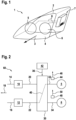
- a lighting device for a motor vehicle is designated in its entirety with the reference number 1.
- the lighting device 1 is designed as a motor vehicle headlight.
- the headlight 1 comprises a housing 2 which is closed by a transparent cover plate 4. In a light exit direction 3, the headlight housing 2 has a light exit opening.
- the headlight 1 comprises two light units 5 and 6, which produce a desired light distribution either alone or in combination with one another.
- the light units 5 and 6 can, for example, be used as reflection modules, projection modules or together to form a light module.
- a control unit 7 is arranged on the outside of the headlight housing 2.
- the control unit 7 can also be an integral part of the lighting units 5 and 6.
- the lighting units 5 and 6 are controlled by the control unit 7 via connecting lines 8, which are Figure 1 are symbolically represented by a dashed line.
- the lighting units 5, 6 are supplied with electrical energy via the cables 8.
- the lighting units 5, 6 each use one or more semiconductor light sources, in particular light-emitting diodes, as light sources.
- Headlights 1 that have a large number of light-emitting diodes are referred to as pixel or matrix headlights.
- parts, in particular a single or multiple light-emitting diodes are dimmed or switched on or off in order to achieve different light distributions.
- FIG. 2 shows a schematic block diagram, which is referred to in its entirety as circuit arrangement 60.
- a first voltage converter 10 is provided for operating the first lighting unit 5.
- a second voltage converter 12 is provided for operating the second lighting unit 6.
- the voltage converters 10 and 12 are each connected to the vehicle electrical system 18 via lines 14 and 16. Alternatively, the Voltage converters 10 and 12 can also be connected to an intermediate voltage and thus to other components in the direction of the on-board network 18.
- On output lines 20 and 22, the voltage converters 10 and 12 generate a voltage level that is different from the input and can be fed to the respective lighting units 5 and 6.
- the output lines 20 and 22 are connected to a switching unit 30, which in normal operation connects the line 20 to a line 32 for operating the lighting unit 5 and connects the line 22 to a line 34 for operating the lighting unit 6.
- the switching unit 30 opens the connection between the lines 20 and 32 and the connection between the lines 22 and 34 and connects the lines 22 and 32 according to a connection path 40 in order to continue operating the lighting unit 5.
- the lighting unit 6 is thereby de-energized.
- the trigger signal 36 is generated by a monitoring unit 42, which detects an error in the area of the voltage converter 10 and/or in the area of the lighting unit 5. In particular, errors in the area of the voltage converter 10 do not lead to the failure of the lighting unit 5 by triggering the connection path 40.
- the sensor signals 46 and 50 are sent to the monitoring unit 42.
- the monitoring unit 42 can carry out a relative comparison of the sensor signals 46 and 50. Furthermore, a comparison of the respective sensor signals 46 and 50 with a corresponding target value can be carried out.
- the trigger signal 36 is determined depending on the evaluation of the sensor signals 46 and 50 or one of the sensor signals 46 and 50.
- the arrangement of the sensors 44 and 48 between the switching unit 30 and the respective lighting unit 5 or 6 makes it easier to distinguish between a malfunction of the lighting unit 5 or 6 and another unit in the direction of the on-board network 18.
- the lighting unit 5 is designed to generate a low beam distribution and the lighting unit 6 is designed to generate a high beam distribution
- a defect can be detected and the path 40 activated by determining a reduction in voltage below a predetermined threshold value on the line 32 using the sensor 44. If the subordinate lighting unit 6 is not active at the time of the defect detection, the voltage converter 10 is deactivated and the voltage converter 12 is activated to operate the lighting unit 5, i.e. switched to operate the lighting unit 5. If the subordinate lighting unit 6 is switched on at the time of the defect detection, it is switched off and the voltage converter 12 is switched to operate the lighting unit 5. The lighting unit 5 is then switched on and an error message is brought to the attention of the driver of the vehicle.
- the voltage converter 12 which is intended for operating the high beam in the sense of the lighting unit 6 in normal operation, thus functions as a reserve for the voltage converter 10 of the low beam 5. Therefore, if the voltage converter 10 fails, the high beam is no longer available, but this is tolerated by maintaining a safe driving condition by means of the active low beam function.
- Figure 3 shows a block diagram of a further embodiment of the circuit arrangement 60.
- a schematic view opposite to the direction of radiation shows how the lighting unit 5 is arranged within the lighting unit 6.
- the lighting unit 5 is assigned a higher operating priority than the lighting unit 6, since the light distribution generated centrally by the lighting unit 5 has a higher operating priority.
- the converter 12 can be used to operate the lighting unit 5 according to the connection path 40.
- the lighting unit 6 is then de-energized.
- the connection paths 52 and 54 are used for normal operation of the headlight.
- the center of a matrix headlight in the form of the lighting unit 5 is more important for the light distribution generated than the edge of the matrix headlight in the form of the lighting unit 6.
Landscapes
- Engineering & Computer Science (AREA)
- Mechanical Engineering (AREA)
- Physics & Mathematics (AREA)
- Microelectronics & Electronic Packaging (AREA)
- Optics & Photonics (AREA)
- General Engineering & Computer Science (AREA)
- Lighting Device Outwards From Vehicle And Optical Signal (AREA)
Claims (3)
- Dispositif d'éclairage, comprenant:- un module lumineux d'un véhicule à moteur, comprenant une première unité d'éclairage (5) et une seconde unité d'éclairage (6), et- un circuit (60) permettant de faire fonctionner les première et seconde unités d'éclairage (5, 6) du module lumineux,chacune des première et seconde unités d'éclairage (5, 6) comprenant une ou plusieurs diode(s) électroluminescente(s) faisant office de source(s) lumineuse(s),caractérisé en ce quele circuit (60) comprend- un premier transformateur de tension (10) destiné au fonctionnement de la première unité d'éclairage (5),- un second transformateur de tension (12) destiné au fonctionnement de la seconde unité d'éclairage (6),- une unité de commutation (30) et- une unité de surveillance (42),en ce que l'unité de commutation (30) est agencée entre les première et seconde unités d'éclairage (5, 6) et les premier et second transformateurs de tension (10, 12),en ce que, en fonctionnement normal, la première unité d'éclairage (5) peut être connectée au premier transformateur de tension (12) et la seconde unité d'éclairage (6) au second transformateur de tension (12) au moyen de l'unité de commutation (30),en ce que l'unité de commutation (30) est conçue pour connecter le second transformateur de tension (12) à la première unité d'éclairage (5) et mettre la seconde unité d'éclairage (6) hors tension, après réception d'un signal de déclenchement (36) généré par l'unité de surveillance (42) qui détermine qu'il existe une défaillance par rapport au premier transformateur de tension (12),en ce que la priorité de fonctionnement attribuée à la première unité d'éclairage (5) est plus élevée que celle attribuée à la seconde unité d'éclairage (6).
- Dispositif d'éclairage selon la revendication 1, caractérisé en ce que le circuit (60) comprend un capteur (44) associé à une ligne (32) du dispositif d'éclairage qui connecte la première unité d'éclairage (5) à l'unité de commutation (30), le capteur (44) étant conçu pour déterminer un signal de capteur, le signal de capteur comprenant un courant ou une tension de la ligne (32) entre le premier transformateur de tension (10) et la première unité d'éclairage (5),le signal de capteur (46) étant fourni à l'unité de surveillance (42), etl'unité de surveillance (42) étant conçue pour déterminer le signal de déclenchement en fonction du signal de capteur (46) fourni.
- Dispositif d'éclairage selon la revendication 2, caractérisé en ce que le second transformateur de tension (12) peut être configuré avec un paramètre de fonctionnement de la première unité d'éclairage (5), qui est une tension de sortie du premier transformateur de tension (10).
Applications Claiming Priority (2)
| Application Number | Priority Date | Filing Date | Title |
|---|---|---|---|
| DE102015213291.9A DE102015213291A1 (de) | 2015-07-15 | 2015-07-15 | Verfahren zum Betreiben einer ersten und einer zweiten Leuchteinheit eines Kraftfahrzeugs und Schaltungsanordnung |
| PCT/EP2016/064716 WO2017009023A1 (fr) | 2015-07-15 | 2016-06-24 | Procédé de fonctionnement d'une première et d'une deuxième unité d'éclairage d'un véhicule à moteur et ensemble commutateur |
Publications (2)
| Publication Number | Publication Date |
|---|---|
| EP3323276A1 EP3323276A1 (fr) | 2018-05-23 |
| EP3323276B1 true EP3323276B1 (fr) | 2024-08-21 |
Family
ID=56203405
Family Applications (1)
| Application Number | Title | Priority Date | Filing Date |
|---|---|---|---|
| EP16731919.3A Active EP3323276B1 (fr) | 2015-07-15 | 2016-06-24 | Disposition des circuits pour une première et une deuxième unité d'éclairage d'un véhicule |
Country Status (4)
| Country | Link |
|---|---|
| US (1) | US10292248B2 (fr) |
| EP (1) | EP3323276B1 (fr) |
| DE (1) | DE102015213291A1 (fr) |
| WO (1) | WO2017009023A1 (fr) |
Families Citing this family (4)
| Publication number | Priority date | Publication date | Assignee | Title |
|---|---|---|---|---|
| FR3083418A1 (fr) * | 2018-06-28 | 2020-01-03 | Valeo Vision | Systeme de pilotage de l'alimentation electrique d'une source lumineuse pixellisee |
| FR3086900B1 (fr) * | 2018-10-04 | 2022-09-09 | Renault Sas | Projecteur pour vehicule automobile |
| JP7505357B2 (ja) * | 2020-09-30 | 2024-06-25 | 市光工業株式会社 | 車両用灯具システム及び車両用灯具 |
| JP7521363B2 (ja) * | 2020-09-30 | 2024-07-24 | 市光工業株式会社 | 車両用灯具システム |
Citations (3)
| Publication number | Priority date | Publication date | Assignee | Title |
|---|---|---|---|---|
| DE10044194A1 (de) * | 1999-09-10 | 2001-03-22 | Koito Mfg Co Ltd | Entladungslampenvorrichtung für Fahrzeuge |
| EP1379108A1 (fr) * | 2002-07-04 | 2004-01-07 | Patent-Treuhand-Gesellschaft für elektrische Glühlampen mbH | Module d'alimentation et d'identification de LED |
| DE102013113007A1 (de) * | 2013-11-25 | 2015-05-28 | Lear Corporation Gmbh | Steuereinrichtung für Außenlichteinheiten von Fahrzeugen |
Family Cites Families (18)
| Publication number | Priority date | Publication date | Assignee | Title |
|---|---|---|---|---|
| FR2656477B1 (fr) * | 1989-12-27 | 1992-08-28 | Sagem | Dispositif de commande d'une charge en remplacement d'une charge defaillante. |
| US5680098A (en) | 1995-09-27 | 1997-10-21 | Ford Motor Company | Circuit for compensating for failure of a light source in an automotive vehicle |
| DE10041888A1 (de) * | 2000-08-25 | 2002-03-07 | Hella Kg Hueck & Co | Steuergerät für ein Fahrzeug |
| DE10109024B4 (de) | 2001-02-24 | 2012-02-02 | Automotive Lighting Reutlingen Gmbh | Spannungswandler |
| DE102005055009A1 (de) * | 2005-11-18 | 2007-05-31 | Daimlerchrysler Ag | Vorrichtung zum Steuern eines Beleuchtungssystems in einem Fahrzeug |
| US8427063B2 (en) | 2009-07-29 | 2013-04-23 | Vektrex Electronic Systems, Inc. | Multicolor LED sequencer |
| DE102009053581B3 (de) | 2009-10-05 | 2011-03-03 | Automotive Lighting Reutlingen Gmbh | Lichtmodul für eine Beleuchtungseinrichtung eines Kraftfahrzeugs |
| US8471486B2 (en) * | 2010-04-21 | 2013-06-25 | Taiwan Semiconductor Manufacturing Company, Ltd. | Energy-saving mechanisms in multi-color display devices |
| CN102347601B (zh) * | 2010-08-04 | 2014-01-22 | 鸿富锦精密工业(深圳)有限公司 | 电源保护电路 |
| DE102010050581A1 (de) | 2010-11-05 | 2012-05-10 | Epcos Ag | Chip mit vier mit akustischen Oberflächenwellen arbeitenden Filtern |
| DE102010050851A1 (de) | 2010-11-09 | 2012-05-10 | Automotive Lighting Reutlingen Gmbh | Verfahren zum Steuern der Helligkeit von Halbleiterlichtquellen eines Kraftfahrzeug und korrespondierende Vorrichtungen |
| DE102011005582A1 (de) * | 2011-03-15 | 2012-09-20 | Automotive Lighting Reutlingen Gmbh | Beleuchtungseinrichtung für ein Kraftfahrzeug mit einer redundanten Ansteuerung von Lichtquellen |
| CN102752902B (zh) * | 2011-04-22 | 2014-10-15 | 登丰微电子股份有限公司 | 发光二极管驱动电路 |
| US9060400B2 (en) * | 2011-07-12 | 2015-06-16 | Arkalumen Inc. | Control apparatus incorporating a voltage converter for controlling lighting apparatus |
| DE102012202290B4 (de) * | 2012-02-15 | 2014-03-27 | Automotive Lighting Reutlingen Gmbh | Lichtmodul für ein blendungsfreies Kraftfahrzeug-Fernlicht |
| DE102013201766A1 (de) | 2013-02-04 | 2014-08-07 | Osram Gmbh | Beleuchtungseinrichtung und Verfahren zum Betreiben einer Beleuchtungseinrichtung |
| JP6688226B2 (ja) * | 2014-12-03 | 2020-04-28 | 株式会社小糸製作所 | 車両用灯具およびその光源の異常検出器 |
| US9974128B2 (en) * | 2014-12-24 | 2018-05-15 | Koito Manufacturing Co., Ltd. | Light source lighting circuit and turn signal lamp |
-
2015
- 2015-07-15 DE DE102015213291.9A patent/DE102015213291A1/de not_active Ceased
-
2016
- 2016-06-24 US US15/744,931 patent/US10292248B2/en active Active
- 2016-06-24 WO PCT/EP2016/064716 patent/WO2017009023A1/fr not_active Ceased
- 2016-06-24 EP EP16731919.3A patent/EP3323276B1/fr active Active
Patent Citations (3)
| Publication number | Priority date | Publication date | Assignee | Title |
|---|---|---|---|---|
| DE10044194A1 (de) * | 1999-09-10 | 2001-03-22 | Koito Mfg Co Ltd | Entladungslampenvorrichtung für Fahrzeuge |
| EP1379108A1 (fr) * | 2002-07-04 | 2004-01-07 | Patent-Treuhand-Gesellschaft für elektrische Glühlampen mbH | Module d'alimentation et d'identification de LED |
| DE102013113007A1 (de) * | 2013-11-25 | 2015-05-28 | Lear Corporation Gmbh | Steuereinrichtung für Außenlichteinheiten von Fahrzeugen |
Also Published As
| Publication number | Publication date |
|---|---|
| WO2017009023A1 (fr) | 2017-01-19 |
| US10292248B2 (en) | 2019-05-14 |
| EP3323276A1 (fr) | 2018-05-23 |
| US20180270937A1 (en) | 2018-09-20 |
| DE102015213291A1 (de) | 2017-01-19 |
Similar Documents
| Publication | Publication Date | Title |
|---|---|---|
| DE102015201739B4 (de) | Fahrzeugleuchte | |
| DE102006015053B4 (de) | LED-Blinker und Fehlerdetektionsverfahren | |
| EP2501206B1 (fr) | Dispositif d'éclairage pour un véhicule automobile doté d'une commande redondante de sources lumineuses | |
| EP3323276B1 (fr) | Disposition des circuits pour une première et une deuxième unité d'éclairage d'un véhicule | |
| EP2390140B1 (fr) | Agencement de circuit | |
| WO2001030119A1 (fr) | Circuit de commande pour del et procede pour faire fonctionner ce circuit | |
| DE102013001274A1 (de) | Verfahren zur Steuerung mehrerer unabhängig voneinander aktivierbarer Dioden in einem Scheinwerfer | |
| DE102012107946A1 (de) | Verfahren für den Betrieb eines Lichtsystems | |
| EP2633738B2 (fr) | Ensemble composé d'un appareil de commande de réseau électrique de bord et d'au moins un variateur d'éclairage d'un véhicule automobile | |
| EP1286567B1 (fr) | Dispositif d' éclairage | |
| DE102005010671A1 (de) | Vorrichtung zur Überwachung der Funktion eines Anzeigeelements | |
| EP4352769A1 (fr) | Système de surveillance optique pour élément d'affichage optique | |
| DE102012102638A1 (de) | Fahrzeugbeleuchtungssysteme mit Detektierung einer Störung in einer der Fahrzeugleuchten | |
| DE102011113080A1 (de) | Verfahren und Vorrichtung zur Diagnose von Leuchtmitteln in einem Fahrzeug | |
| DE102005063344B4 (de) | Vorrichtung zum Ansteuern von Fahrzeuglampen | |
| DE102012222013B4 (de) | Kombinierte Steuervorrichtung und Verfahren für eine Leuchte eines Fahrzeugs | |
| EP3826875B1 (fr) | Système de surveillance automatique de la signalisation de l'état du véhicule et procédé de surveillance d'un dispositif de signalisation de l'état du véhicule | |
| DE102024114173B3 (de) | Verfahren zur Steuerung einer Projektionseinrichtung eines Matrixscheinwerfers und Matrixscheinwerfer | |
| DE102014204386A1 (de) | Verfahren zur Steuerung einer Beleuchtungseinrichtung in einem Kraftfahrzeug | |
| DE202010016339U1 (de) | Schaltungsanordnung | |
| DE10103951B4 (de) | Energieversorgungseinrichtung für bordnetzgestützte, sicherheitsrelevante Systemkomponenten von Fahrzeugen | |
| DE102010000312B3 (de) | Vorrichtung zum Betreiben von Anhängerleuchten | |
| EP2469985B1 (fr) | Dispositif et procédé pour garantir l'exploitation correcte de lampes à DEL en combinaison avec des ordinateurs de bord de véhicules | |
| DE20115409U1 (de) | Elektrische Beleuchtungsanlage | |
| DE102014017716A1 (de) | Arbeitsmaschine |
Legal Events
| Date | Code | Title | Description |
|---|---|---|---|
| STAA | Information on the status of an ep patent application or granted ep patent |
Free format text: STATUS: THE INTERNATIONAL PUBLICATION HAS BEEN MADE |
|
| PUAI | Public reference made under article 153(3) epc to a published international application that has entered the european phase |
Free format text: ORIGINAL CODE: 0009012 |
|
| STAA | Information on the status of an ep patent application or granted ep patent |
Free format text: STATUS: REQUEST FOR EXAMINATION WAS MADE |
|
| 17P | Request for examination filed |
Effective date: 20180110 |
|
| AK | Designated contracting states |
Kind code of ref document: A1 Designated state(s): AL AT BE BG CH CY CZ DE DK EE ES FI FR GB GR HR HU IE IS IT LI LT LU LV MC MK MT NL NO PL PT RO RS SE SI SK SM TR |
|
| AX | Request for extension of the european patent |
Extension state: BA ME |
|
| DAV | Request for validation of the european patent (deleted) | ||
| DAX | Request for extension of the european patent (deleted) | ||
| STAA | Information on the status of an ep patent application or granted ep patent |
Free format text: STATUS: EXAMINATION IS IN PROGRESS |
|
| 17Q | First examination report despatched |
Effective date: 20200417 |
|
| REG | Reference to a national code |
Ref country code: DE Ref legal event code: R079 Free format text: PREVIOUS MAIN CLASS: H05B0037030000 Ipc: H05B0047200000 Ref document number: 502016016683 Country of ref document: DE |
|
| GRAP | Despatch of communication of intention to grant a patent |
Free format text: ORIGINAL CODE: EPIDOSNIGR1 |
|
| STAA | Information on the status of an ep patent application or granted ep patent |
Free format text: STATUS: GRANT OF PATENT IS INTENDED |
|
| RIC1 | Information provided on ipc code assigned before grant |
Ipc: H05B 47/20 20200101AFI20240229BHEP |
|
| INTG | Intention to grant announced |
Effective date: 20240318 |
|
| GRAS | Grant fee paid |
Free format text: ORIGINAL CODE: EPIDOSNIGR3 |
|
| GRAA | (expected) grant |
Free format text: ORIGINAL CODE: 0009210 |
|
| STAA | Information on the status of an ep patent application or granted ep patent |
Free format text: STATUS: THE PATENT HAS BEEN GRANTED |
|
| AK | Designated contracting states |
Kind code of ref document: B1 Designated state(s): AL AT BE BG CH CY CZ DE DK EE ES FI FR GB GR HR HU IE IS IT LI LT LU LV MC MK MT NL NO PL PT RO RS SE SI SK SM TR |
|
| P01 | Opt-out of the competence of the unified patent court (upc) registered |
Free format text: CASE NUMBER: APP_41518/2024 Effective date: 20240715 |
|
| RAP3 | Party data changed (applicant data changed or rights of an application transferred) |
Owner name: MARELLI AUTOMOTIVE LIGHTING REUTLINGEN (GERMANY)GMBH |
|
| REG | Reference to a national code |
Ref country code: GB Ref legal event code: FG4D Free format text: NOT ENGLISH |
|
| REG | Reference to a national code |
Ref country code: CH Ref legal event code: EP |
|
| REG | Reference to a national code |
Ref country code: IE Ref legal event code: FG4D Free format text: LANGUAGE OF EP DOCUMENT: GERMAN |
|
| REG | Reference to a national code |
Ref country code: DE Ref legal event code: R096 Ref document number: 502016016683 Country of ref document: DE |
|
| REG | Reference to a national code |
Ref country code: LT Ref legal event code: MG9D |
|
| REG | Reference to a national code |
Ref country code: NL Ref legal event code: MP Effective date: 20240821 |
|
| PG25 | Lapsed in a contracting state [announced via postgrant information from national office to epo] |
Ref country code: NO Free format text: LAPSE BECAUSE OF FAILURE TO SUBMIT A TRANSLATION OF THE DESCRIPTION OR TO PAY THE FEE WITHIN THE PRESCRIBED TIME-LIMIT Effective date: 20241121 |
|
| PG25 | Lapsed in a contracting state [announced via postgrant information from national office to epo] |
Ref country code: GR Free format text: LAPSE BECAUSE OF FAILURE TO SUBMIT A TRANSLATION OF THE DESCRIPTION OR TO PAY THE FEE WITHIN THE PRESCRIBED TIME-LIMIT Effective date: 20241122 Ref country code: PL Free format text: LAPSE BECAUSE OF FAILURE TO SUBMIT A TRANSLATION OF THE DESCRIPTION OR TO PAY THE FEE WITHIN THE PRESCRIBED TIME-LIMIT Effective date: 20240821 Ref country code: FI Free format text: LAPSE BECAUSE OF FAILURE TO SUBMIT A TRANSLATION OF THE DESCRIPTION OR TO PAY THE FEE WITHIN THE PRESCRIBED TIME-LIMIT Effective date: 20240821 Ref country code: PT Free format text: LAPSE BECAUSE OF FAILURE TO SUBMIT A TRANSLATION OF THE DESCRIPTION OR TO PAY THE FEE WITHIN THE PRESCRIBED TIME-LIMIT Effective date: 20241223 Ref country code: NL Free format text: LAPSE BECAUSE OF FAILURE TO SUBMIT A TRANSLATION OF THE DESCRIPTION OR TO PAY THE FEE WITHIN THE PRESCRIBED TIME-LIMIT Effective date: 20240821 |
|
| PG25 | Lapsed in a contracting state [announced via postgrant information from national office to epo] |
Ref country code: BG Free format text: LAPSE BECAUSE OF FAILURE TO SUBMIT A TRANSLATION OF THE DESCRIPTION OR TO PAY THE FEE WITHIN THE PRESCRIBED TIME-LIMIT Effective date: 20240821 |
|
| PG25 | Lapsed in a contracting state [announced via postgrant information from national office to epo] |
Ref country code: LV Free format text: LAPSE BECAUSE OF FAILURE TO SUBMIT A TRANSLATION OF THE DESCRIPTION OR TO PAY THE FEE WITHIN THE PRESCRIBED TIME-LIMIT Effective date: 20240821 |
|
| PG25 | Lapsed in a contracting state [announced via postgrant information from national office to epo] |
Ref country code: IS Free format text: LAPSE BECAUSE OF FAILURE TO SUBMIT A TRANSLATION OF THE DESCRIPTION OR TO PAY THE FEE WITHIN THE PRESCRIBED TIME-LIMIT Effective date: 20241221 |
|
| PG25 | Lapsed in a contracting state [announced via postgrant information from national office to epo] |
Ref country code: HR Free format text: LAPSE BECAUSE OF FAILURE TO SUBMIT A TRANSLATION OF THE DESCRIPTION OR TO PAY THE FEE WITHIN THE PRESCRIBED TIME-LIMIT Effective date: 20240821 |
|
| PG25 | Lapsed in a contracting state [announced via postgrant information from national office to epo] |
Ref country code: RS Free format text: LAPSE BECAUSE OF FAILURE TO SUBMIT A TRANSLATION OF THE DESCRIPTION OR TO PAY THE FEE WITHIN THE PRESCRIBED TIME-LIMIT Effective date: 20241121 Ref country code: ES Free format text: LAPSE BECAUSE OF FAILURE TO SUBMIT A TRANSLATION OF THE DESCRIPTION OR TO PAY THE FEE WITHIN THE PRESCRIBED TIME-LIMIT Effective date: 20240821 |
|
| PG25 | Lapsed in a contracting state [announced via postgrant information from national office to epo] |
Ref country code: RS Free format text: LAPSE BECAUSE OF FAILURE TO SUBMIT A TRANSLATION OF THE DESCRIPTION OR TO PAY THE FEE WITHIN THE PRESCRIBED TIME-LIMIT Effective date: 20241121 Ref country code: PT Free format text: LAPSE BECAUSE OF FAILURE TO SUBMIT A TRANSLATION OF THE DESCRIPTION OR TO PAY THE FEE WITHIN THE PRESCRIBED TIME-LIMIT Effective date: 20241223 Ref country code: PL Free format text: LAPSE BECAUSE OF FAILURE TO SUBMIT A TRANSLATION OF THE DESCRIPTION OR TO PAY THE FEE WITHIN THE PRESCRIBED TIME-LIMIT Effective date: 20240821 Ref country code: NO Free format text: LAPSE BECAUSE OF FAILURE TO SUBMIT A TRANSLATION OF THE DESCRIPTION OR TO PAY THE FEE WITHIN THE PRESCRIBED TIME-LIMIT Effective date: 20241121 Ref country code: NL Free format text: LAPSE BECAUSE OF FAILURE TO SUBMIT A TRANSLATION OF THE DESCRIPTION OR TO PAY THE FEE WITHIN THE PRESCRIBED TIME-LIMIT Effective date: 20240821 Ref country code: LV Free format text: LAPSE BECAUSE OF FAILURE TO SUBMIT A TRANSLATION OF THE DESCRIPTION OR TO PAY THE FEE WITHIN THE PRESCRIBED TIME-LIMIT Effective date: 20240821 Ref country code: IS Free format text: LAPSE BECAUSE OF FAILURE TO SUBMIT A TRANSLATION OF THE DESCRIPTION OR TO PAY THE FEE WITHIN THE PRESCRIBED TIME-LIMIT Effective date: 20241221 Ref country code: HR Free format text: LAPSE BECAUSE OF FAILURE TO SUBMIT A TRANSLATION OF THE DESCRIPTION OR TO PAY THE FEE WITHIN THE PRESCRIBED TIME-LIMIT Effective date: 20240821 Ref country code: GR Free format text: LAPSE BECAUSE OF FAILURE TO SUBMIT A TRANSLATION OF THE DESCRIPTION OR TO PAY THE FEE WITHIN THE PRESCRIBED TIME-LIMIT Effective date: 20241122 Ref country code: FI Free format text: LAPSE BECAUSE OF FAILURE TO SUBMIT A TRANSLATION OF THE DESCRIPTION OR TO PAY THE FEE WITHIN THE PRESCRIBED TIME-LIMIT Effective date: 20240821 Ref country code: ES Free format text: LAPSE BECAUSE OF FAILURE TO SUBMIT A TRANSLATION OF THE DESCRIPTION OR TO PAY THE FEE WITHIN THE PRESCRIBED TIME-LIMIT Effective date: 20240821 Ref country code: BG Free format text: LAPSE BECAUSE OF FAILURE TO SUBMIT A TRANSLATION OF THE DESCRIPTION OR TO PAY THE FEE WITHIN THE PRESCRIBED TIME-LIMIT Effective date: 20240821 |
|
| PG25 | Lapsed in a contracting state [announced via postgrant information from national office to epo] |
Ref country code: DK Free format text: LAPSE BECAUSE OF FAILURE TO SUBMIT A TRANSLATION OF THE DESCRIPTION OR TO PAY THE FEE WITHIN THE PRESCRIBED TIME-LIMIT Effective date: 20240821 Ref country code: SM Free format text: LAPSE BECAUSE OF FAILURE TO SUBMIT A TRANSLATION OF THE DESCRIPTION OR TO PAY THE FEE WITHIN THE PRESCRIBED TIME-LIMIT Effective date: 20240821 Ref country code: RO Free format text: LAPSE BECAUSE OF FAILURE TO SUBMIT A TRANSLATION OF THE DESCRIPTION OR TO PAY THE FEE WITHIN THE PRESCRIBED TIME-LIMIT Effective date: 20240821 |
|
| PG25 | Lapsed in a contracting state [announced via postgrant information from national office to epo] |
Ref country code: EE Free format text: LAPSE BECAUSE OF FAILURE TO SUBMIT A TRANSLATION OF THE DESCRIPTION OR TO PAY THE FEE WITHIN THE PRESCRIBED TIME-LIMIT Effective date: 20240821 |
|
| PG25 | Lapsed in a contracting state [announced via postgrant information from national office to epo] |
Ref country code: CZ Free format text: LAPSE BECAUSE OF FAILURE TO SUBMIT A TRANSLATION OF THE DESCRIPTION OR TO PAY THE FEE WITHIN THE PRESCRIBED TIME-LIMIT Effective date: 20240821 |
|
| PG25 | Lapsed in a contracting state [announced via postgrant information from national office to epo] |
Ref country code: SK Free format text: LAPSE BECAUSE OF FAILURE TO SUBMIT A TRANSLATION OF THE DESCRIPTION OR TO PAY THE FEE WITHIN THE PRESCRIBED TIME-LIMIT Effective date: 20240821 Ref country code: IT Free format text: LAPSE BECAUSE OF FAILURE TO SUBMIT A TRANSLATION OF THE DESCRIPTION OR TO PAY THE FEE WITHIN THE PRESCRIBED TIME-LIMIT Effective date: 20240821 |
|
| REG | Reference to a national code |
Ref country code: DE Ref legal event code: R097 Ref document number: 502016016683 Country of ref document: DE |
|
| PLBE | No opposition filed within time limit |
Free format text: ORIGINAL CODE: 0009261 |
|
| STAA | Information on the status of an ep patent application or granted ep patent |
Free format text: STATUS: NO OPPOSITION FILED WITHIN TIME LIMIT |
|
| PGFP | Annual fee paid to national office [announced via postgrant information from national office to epo] |
Ref country code: DE Payment date: 20250520 Year of fee payment: 10 |
|
| PGFP | Annual fee paid to national office [announced via postgrant information from national office to epo] |
Ref country code: FR Payment date: 20250520 Year of fee payment: 10 |
|
| 26N | No opposition filed |
Effective date: 20250522 |
|
| PG25 | Lapsed in a contracting state [announced via postgrant information from national office to epo] |
Ref country code: SE Free format text: LAPSE BECAUSE OF FAILURE TO SUBMIT A TRANSLATION OF THE DESCRIPTION OR TO PAY THE FEE WITHIN THE PRESCRIBED TIME-LIMIT Effective date: 20240821 |
|
| REG | Reference to a national code |
Ref country code: DE Ref legal event code: R081 Ref document number: 502016016683 Country of ref document: DE Owner name: MARELLI GERMANY GMBH, DE Free format text: FORMER OWNER: MARELLI AUTOMOTIVE LIGHTING REUTLINGEN (GERMANY) GMBH, 72762 REUTLINGEN, DE |
|
| REG | Reference to a national code |
Ref country code: CH Ref legal event code: H13 Free format text: ST27 STATUS EVENT CODE: U-0-0-H10-H13 (AS PROVIDED BY THE NATIONAL OFFICE) Effective date: 20260127 |
|
| PG25 | Lapsed in a contracting state [announced via postgrant information from national office to epo] |
Ref country code: MC Free format text: LAPSE BECAUSE OF FAILURE TO SUBMIT A TRANSLATION OF THE DESCRIPTION OR TO PAY THE FEE WITHIN THE PRESCRIBED TIME-LIMIT Effective date: 20240821 |
|
| PG25 | Lapsed in a contracting state [announced via postgrant information from national office to epo] |
Ref country code: LU Free format text: LAPSE BECAUSE OF NON-PAYMENT OF DUE FEES Effective date: 20250624 |
|
| GBPC | Gb: european patent ceased through non-payment of renewal fee |
Effective date: 20250624 |
|
| REG | Reference to a national code |
Ref country code: BE Ref legal event code: MM Effective date: 20250630 |
|
| PG25 | Lapsed in a contracting state [announced via postgrant information from national office to epo] |
Ref country code: GB Free format text: LAPSE BECAUSE OF NON-PAYMENT OF DUE FEES Effective date: 20250624 |
|
| PG25 | Lapsed in a contracting state [announced via postgrant information from national office to epo] |
Ref country code: IE Free format text: LAPSE BECAUSE OF NON-PAYMENT OF DUE FEES Effective date: 20250624 |
|
| PG25 | Lapsed in a contracting state [announced via postgrant information from national office to epo] |
Ref country code: BE Free format text: LAPSE BECAUSE OF NON-PAYMENT OF DUE FEES Effective date: 20250630 |