EP3323301A1 - Dispositif de contrôle, de traitement et/ou de transport d'articles de l'industrie de traitement du tabac - Google Patents
Dispositif de contrôle, de traitement et/ou de transport d'articles de l'industrie de traitement du tabac Download PDFInfo
- Publication number
- EP3323301A1 EP3323301A1 EP17202674.2A EP17202674A EP3323301A1 EP 3323301 A1 EP3323301 A1 EP 3323301A1 EP 17202674 A EP17202674 A EP 17202674A EP 3323301 A1 EP3323301 A1 EP 3323301A1
- Authority
- EP
- European Patent Office
- Prior art keywords
- interface unit
- transmission
- unit
- data
- data signal
- Prior art date
- Legal status (The legal status is an assumption and is not a legal conclusion. Google has not performed a legal analysis and makes no representation as to the accuracy of the status listed.)
- Granted
Links
Images


Classifications
-
- A—HUMAN NECESSITIES
- A24—TOBACCO; CIGARS; CIGARETTES; SIMULATED SMOKING DEVICES; SMOKERS' REQUISITES
- A24C—MACHINES FOR MAKING CIGARS OR CIGARETTES
- A24C5/00—Making cigarettes; Making tipping materials for, or attaching filters or mouthpieces to, cigars or cigarettes
- A24C5/32—Separating, ordering, counting or examining cigarettes; Regulating the feeding of tobacco according to rod or cigarette condition
- A24C5/34—Examining cigarettes or the rod, e.g. for regulating the feeding of tobacco; Removing defective cigarettes
-
- H—ELECTRICITY
- H02—GENERATION; CONVERSION OR DISTRIBUTION OF ELECTRIC POWER
- H02J—ELECTRIC POWER NETWORKS; CIRCUIT ARRANGEMENTS OR SYSTEMS FOR SUPPLYING OR DISTRIBUTING ELECTRIC POWER; SYSTEMS FOR STORING ELECTRIC ENERGY
- H02J50/00—Circuit arrangements or systems for wireless supply or distribution of electric power
- H02J50/10—Circuit arrangements or systems for wireless supply or distribution of electric power using inductive coupling
-
- A—HUMAN NECESSITIES
- A24—TOBACCO; CIGARS; CIGARETTES; SIMULATED SMOKING DEVICES; SMOKERS' REQUISITES
- A24C—MACHINES FOR MAKING CIGARS OR CIGARETTES
- A24C5/00—Making cigarettes; Making tipping materials for, or attaching filters or mouthpieces to, cigars or cigarettes
-
- A—HUMAN NECESSITIES
- A24—TOBACCO; CIGARS; CIGARETTES; SIMULATED SMOKING DEVICES; SMOKERS' REQUISITES
- A24C—MACHINES FOR MAKING CIGARS OR CIGARETTES
- A24C5/00—Making cigarettes; Making tipping materials for, or attaching filters or mouthpieces to, cigars or cigarettes
- A24C5/32—Separating, ordering, counting or examining cigarettes; Regulating the feeding of tobacco according to rod or cigarette condition
- A24C5/322—Transporting cigarettes during manufacturing
- A24C5/327—Construction details of the cigarette transport drum
-
- A—HUMAN NECESSITIES
- A24—TOBACCO; CIGARS; CIGARETTES; SIMULATED SMOKING DEVICES; SMOKERS' REQUISITES
- A24C—MACHINES FOR MAKING CIGARS OR CIGARETTES
- A24C5/00—Making cigarettes; Making tipping materials for, or attaching filters or mouthpieces to, cigars or cigarettes
- A24C5/32—Separating, ordering, counting or examining cigarettes; Regulating the feeding of tobacco according to rod or cigarette condition
- A24C5/33—Catching or ordering devices
- A24C5/336—Turning means
-
- A—HUMAN NECESSITIES
- A24—TOBACCO; CIGARS; CIGARETTES; SIMULATED SMOKING DEVICES; SMOKERS' REQUISITES
- A24C—MACHINES FOR MAKING CIGARS OR CIGARETTES
- A24C5/00—Making cigarettes; Making tipping materials for, or attaching filters or mouthpieces to, cigars or cigarettes
- A24C5/35—Adaptations of conveying apparatus for transporting cigarettes from making machine to packaging machine
Definitions
- the invention relates to a device for testing, processing and / or conveying articles of the tobacco processing industry, with at least one rotationally driven base body, on or in which at least one electrical load is arranged, and a coupled to the electrical load transmission device, which is a rotation transmission unit having a stationary primary part and a secondary part connected to the main body, wherein the rotary transmission unit contains first energy transmission means for supplying energy to the electrical consumer and data signal transmission means for transmitting signals to or from the electrical consumer.
- Electric motors are used in particular as electric motors which operate independently of a drive unit rotatingly driving the main body and preferably also independently of one another and drive components movably arranged on the main body.
- the advantage of such Solution over a mechanical gear assembly is in particular in a lower wear and thus in a reduced maintenance.
- Another important advantage over a mechanical gear arrangement is a simple separate controllability of the electric motors and thus the components driven by them, which can be achieved, for example, to a far simpler constructive manner a much more flexible operation of the entire device or system.
- the turning device for turning cigarettes, as used in a filter attachment machine.
- the rotation of every second cigarette is necessary so that the cigarettes can be packed in the same orientation, so that the mouthpieces are each oriented to open a cigarette box.
- the turning device as a rotatably driven base body on a drum on which are provided for rotation of the cigarette turning segments in the form of turntables, which are independent of the drum and driven independently by electric motors.
- the transmission device has a stationary first interface unit and arranged on or in the main body second interface unit, the first interface unit connected via an electrical line to the primary part of the rotary transmission unit and for feeding a first electrical supply voltage for the power supply of the electrical load into the first energy transfer means and the second interface unit for transferring the energy received from the first energy transfer means to the at least one electrical load
- the first interface unit comprises modulation means which are the ones of the first interface unit received, having a specific data format data in suitable for transmission via the rotation transmission unit proprietary signals converting and / or demodulation means, the return from the rotation transmission unit obtained proprietary signals in the particular data format data back, and the second interface unit modulating means, the second interface unit received, the particular data format having data signals in suitable for transmission via the rotation transmission unit to convert proprietary signals, and / or demodulation means, which convert back from the rotation transmission unit obtained proprietary signals in the particular data format having data signals.
- the power and the data are transmitted in common via the rotary transmission unit; however, moreover, the power and data signal paths are substantially separated from each other. It has been found that with such a solution, a rapid startup of the electrical load and thus ultimately the entire device or system is made possible by the data signal path remains active despite interruption of the operation by switching off the power path and thus the electrical load. Because it has been found that in the case of a simultaneous shutdown and thus interruption of the data signal path when restarting and reactivation of the data signal path, the startup of the signal data transmission and processing takes a certain amount of time, which has a negative impact on the starting behavior and operational readiness of the entire device or System can affect.
- Another feature of this invention is that essential functions heretofore implemented in a conventional rotary transfer unit are outsourced from the rotary transfer unit to the stationary first interface unit provided in accordance with the invention and the second interface unit also provided in accordance with the invention.
- a hybrid line can preferably be provided, in which the power and data signal paths in the form of power and data signal lines combined, whereby it is achieved that the two interface units and the rotation transmission unit can only be connected to each other via a single cable.
- the inventive outsourcing of functions from the rotary transfer unit in the interface units leads to a significant reduction in the design of the rotary transfer unit, which is a significant advantage for use in a device for testing, processing and / or conveying articles of the tobacco processing industry, since there Space, especially at the points where the rotation transfer unit would have to be arranged, is quite scarce.
- the inventive conversion of the data having a specific data format used in suitable for transmission via the rotary transmission unit proprietary signals, the data can be transmitted in a simple and reliable manner without predetermined by the particular data format constraints used.
- the solution of the invention further allows easy integration into an existing machine automation.
- the last-mentioned advantage has a particularly positive effect if a data signal processing device connected to the data signal transmission means and coupled to the at least one electrical load is provided on or in the main body and a data bus is connected to the first interface unit for transmitting the data having the particular data format and the same data bus connects the second interface unit to the data signal processing means.
- the data bus is preferably the EtherCAT bus.
- a further preferred embodiment of the invention is characterized in that the first electrical supply voltage is an AC voltage, the first interface unit comprises a rectifier, which converts the first supply voltage into a DC voltage which is supplied via the electrical line to the primary part of the rotary transmission unit, in the first interface unit or in the primary part of the rotary transmission unit inverter means for converting the converted DC voltage into a suitable for the transmission to the secondary part of the rotation transmission unit first AC voltage, and the second interface unit comprises rectifying means, which converts the first AC voltage into a first DC output voltage for supplying the at least one electrical load.
- DC voltage to transmit the required electrical power to the electrical load from the first interface unit via the rotary transmission unit to the second interface unit, the inductive and capacitive losses associated with AC power lines can be avoided.
- At least one power converter is provided on or in the main body, which is connected between the second interface unit and the at least one electrical load.
- an arrangement of the power converter separate from the second interface unit on or in the base structural advantages, since the individual of these components taken by themselves take up a relatively small space.
- the above object is further achieved according to a second aspect of the invention in a device of the type mentioned above in that on or in the base body connected to the data signal transmission means and coupled to the at least one electrical load data signal processing means is provided and the rotation transfer unit second energy transfer means for contains separate power supply of the data signal processing device.
- this aspect according to the invention which incidentally also forms an independent idea of the invention, enables supply of the data signal processing device and its components with the energy required for them, which is independent of the remaining transmission paths and thus particularly reliable Supply of electrical consumers with relatively high energy can also be referred to as auxiliary power.
- the data signal processing device continues to be supplied with energy safely.
- the data signal processing device remains ready for use and does not need to restart when the electrical consumers are reactivated by reactivation of the first energy transmission means, as a result of which the entire device or system can be started up much more quickly and thus is much faster ready for use.
- the rotation transfer unit includes three routes, namely a first power path for transmitting the power to supply the electrical load, a second power path for transmitting the auxiliary power for the data signal processing device and a data signal path.
- the first interface unit should preferably be designed for additional supply of a second electrical supply voltage for the separate power supply of the data signal processing device and the second interface unit for forwarding of the auxiliary energy obtained via the second energy transfer means to the data signal processing device.
- this second electrical supply voltage can be a DC voltage.
- a particularly preferred embodiment of the invention is characterized in that the rotation transmission unit is designed as a contactless rotational transmission unit, wherein preferably the energy transmission means and / or the data signal transmission means capacitive and / or optical work.
- the rotation transmission unit is designed as a contactless rotational transmission unit, wherein preferably the energy transmission means and / or the data signal transmission means capacitive and / or optical work.
- the data signal path has a capacitive sub-path for transmitting internal signals and an optical sub-section for transmitting useful data.
- a further preferred embodiment has a safety device which, in a first operating state, prevents contact of critical and in particular health-endangering parts of the device during its operation and, in a second operating state, allows access to these parts during standstill of the device, and is characterized in that the safety device is designed such that, in its first operating state, it leaves the function of the first and second energy transmission means and the data signal transmission means unaffected and in its second operating state causes deactivation or deactivation of the first energy transmission means, but still leaves the function of the second energy transmission means and the data signal transmission means unaffected , Accordingly, while the first operating state forms the so-called normal state in which the device operates normally without any interruptions or malfunctions, the second operating state defines a state in which, for example, due to maintenance work or due to a malfunction, the electrical consumers are switched off and thus the device is stationary.
- the safety device If the safety device has to intervene and become active, then according to the invention it effects only the disconnection of the first energy transmission means, whereby only the electrical consumers are switched off and thus the electrical energy to be classified as hazardous to contact is no longer available.
- the safety device according to the invention does not affect the function of the second energy transmission means and the data signal transmission means, so that the data signal processing device continues to be active and reachable even in the event of an interruption or malfunction, thus ensuring a quick operational readiness of the entire device.
- the safety device has at least one cover which is closed in the first operating state and open in the second operating state, and a monitoring unit which switches off or at least deactivates the first transmission means when the cover is opened.
- the monitoring unit may have a responsive to the opening of the cover sensor and a safety relay.
- the safety device can also be designed so that it causes a shutdown of the first electrical supply voltage before feeding into the first interface unit in its second operating state and thus engages at a point of power supply already before the first interface unit.
- a further preferred embodiment of the invention in which a cooling device is provided for cooling at least some parts of the device, is characterized in that the rotary transmission unit is arranged in the effective range of the cooling device.
- the cooling device is used multiple times, namely on the one hand for cooling components of the device and on the other hand for dissipating heat generated in the rotary transfer unit, which has a positive effect on the performance, reliability and life of the rotary transmission unit effect.
- the device is provided with a vacuum supply device for generating negative pressure at certain parts or aggregates of the device, such as in the wells of drum mills for fixing the rod-shaped smoking article, preferably such a vacuum supply device can also take over the function of the cooling device, wherein preferably the rotation transfer unit at least partially to be arranged in an air flow generated by such a vacuum supply device.
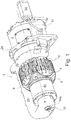
- FIGS. 1 . 2 and 4 is schematically shown a preferred embodiment of an apparatus according to the invention for testing, processing and / or conveying articles of the tobacco processing industry.
- the device has a housing 2 with a mounting flange 2a, on which a drum is rotatably mounted, which is formed in the illustrated embodiment as a turning drum 4.
- the turning drum 4 has a rotating base body 6, on which distributed over its circumference turntable 8 are arranged.
- four turntable 8 are provided.
- the turntables 8 are rotatably mounted on the base body 6 about an axis of rotation, not shown in the figures, which is radially oriented with respect to the rotation axis of the base body 6, also not shown in the figures.
- the turntable 8 are provided on its surface with a plurality of parallel adjacent troughs 9 for receiving cigarettes.
- the basic body 6 may alternatively also be part of a sliding drum, spreading drum or rotating cutting device or a test carousel or knife carrier.
- the main body 6 is rotationally driven by an electric motor 10 arranged on the housing 2 via a transmission 12 provided inside the housing 2.
- the turntables 8, in contrast, are rotationally driven by their own electric motors 14, which are arranged inside the main body 6, like the Figures 2 and 4 reveal.
- the the turntable 8 in rotation staggering Electric motors 14 within the body 6 operate basically independently and also independently of the rotating body 6 driving electric motor 10.
- the electric motors 14 are supplied with power and control signals via a transmission device, which is provided in a preferred embodiment according to the invention and explained in more detail below , where already at this point the sake of completeness, it should be noted that this transfer device is in principle suitable to be used also for supplying other electrical consumers to be provided on or in the base body 6.
- an outboard curved suction tube 20 which has a flange-like end 20a.
- a suction device not shown in the figures can be connected, which sucks air from the interior 22 of the suction tube 20 via its outlet 22a.
- the suction tube 20 is connected with its interior 22 via a first cavity 24 formed in the troughs 9 of the turntable 8, not shown in the figures suction ports.
- the suction tube 20 and the suction device to be connected thereto for generating a negative pressure in the wells 9 of the turntable 8 is used to suck rod-shaped smoking articles such as tobacco sticks or finished cigarettes and to fix in the wells 9.
- the first cavity 24 communicates with a relative to the turning drum 4 upstream second cavity 25 and this in turn with a formed within the housing 2 third cavity 26.
- the formation of coupled to the suction tube 20 arrangement of the communicating cavities 24th , 25, 26 further serves for cooling components in the immediate vicinity or at least in the vicinity, in order to dissipate the heat generated there by means of air flow.
- the upstream third cavity 26 communicates via an inlet opening with the environment formed in the housing 2, but not shown in the figures.
- the arrangement of suction tube 20 and attached thereto suction device also serves as a cooling device at least for those components which lie adjacent to the cavities 24 to 26 and at which thus the air flow flows along.
- a suitable transmission device is to be provided for the power supply and control of the electric motors 14. Because of the special feature that the electric motors 14 to be supplied are arranged within the rotating basic body 6, the transmission device is to be designed accordingly to transfer the energy and signal data transmission from a stationary environment into a rotating environment, namely onto the rotating main body 6.
- FIG. 3 Such a transfer device 30 according to a preferred embodiment of the invention is shown.
- the individual components in a relative positioning shown to each other, as they are also when installed in the device of Fig. 1 is given, what the FIGS. 1 and 3 according to their perspective.
- Fig. 3 incidentally, also in conjunction with the FIGS. 4 and 5 , can recognize, has the illustrated transfer device 30 to a stationary first interface unit 32, which in particular the FIGS. 1 and 2 can recognize, is arranged stationary outside the housing 2 and therefore can also be referred to as a so-called. "Statorbox". From the first interface unit 32 leads a hybrid cable 34 via a hybrid connector 36 to a stationary primary part 38a of a contactless Drehübertragers 38, which is also part of the transfer device 30.
- the rotary transformer 38 is disposed within an additional housing 40 which is connected to the housing 2 is substantially rigid. In this case, the stationary primary part 38a of the rotary transformer 38 is fixed against rotation relative to the additional housing 40.
- the contactless rotary transformer 38 a rotating secondary part 38b, which is rotatably coupled to the rotating body 6.
- a cable 41 leads to a second interface unit 42, which in or is rotatably arranged on the rotating body 6 with respect to this and therefore can also be referred to as a so-called "rotor box".
- connection cable 44 to power converters 46 which are rotatably disposed within the housing 2 relative to the rotating body 6;
- the power converters 46 may be attached, for example, to the output shaft of the transmission 12, which is coupled to the rotating main body 6 and not visible in the figures, or to a scaffold, likewise not shown, mounted on the rotating main body 6.
- the thus relative to the rotating body 6 rotatably arranged power converters 46 thus rotate synchronously with the main body 6.
- Fig. 2 can also be seen, leads from the power converters 46, a connecting cable 48 to the electric motors 14 so that they are powered by the power converters 46 with energy.
- the first interface unit 32 includes a rectifier 52, which converts the voltage from the voltage source 50 into a DC voltage, which is supplied via the hybrid cable 34 to the primary part 38 a of the rotary transformer 38.
- the hybrid cable 34 has a separate first power path in the form of a first electrical line 34a, via which the DC voltage is transmitted from the rectifier 52 in the first interface unit 32 to the primary part 38a of the rotary transformer 38.
- this DC voltage is in a range of 24V to 400V and in particular has a value of 120V.
- the rotary transformer 38 includes an inverter 39 which is housed according to the illustrated embodiment in the primary part 38a of the rotary transformer 38. The aforementioned, within the hybrid cable 34 guided first electrical line 34a is connected to this inverter 39, so that the transmitted via the first electrical line 34a DC voltage is converted into a suitable for transmission to the secondary part 38b of the rotary transformer 38 AC voltage.
- This AC voltage is preferably a high-frequency AC voltage of 120V.
- a separate transformer stage with contactless first energy transmission means 54a, 54b is provided in the rotary transformer 38, of which one energy transfer means 54a in the primary part 38a and the other energy transfer means 54b in the secondary part 38b of Drehübertragers 38 is provided.
- the first energy transfer means 54a, 54b operate inductively.
- the high-frequency alternating voltage transmitted contactlessly by the first energy transmission means 54a, 54b thus abuts the output of the secondary part 38b of the rotary transformer within the rotating main body 2 and is transmitted from there via the cable 41 to the so-called "rotor box" or second interface unit 42.
- the second interface unit 42 includes a rectifier 56, which converts the said high-frequency AC voltage into DC voltage, which preferably has a value of 48V.
- This DC voltage is transmitted via the connecting cable 44 to the power converters 46, which are provided for the power supply of the electric motors 14.
- a data signal path which has a data bus 60 which is connected to the first interface unit 32, such as Fig. 4 can be seen schematically.
- Data is transmitted bidirectionally in a given specific data format via this data bus 60.
- an EtherCAT data bus is used as the data bus.
- the data bus 60 is coupled to a first bidirectional modulation device 62, which is additionally in the first interface unit 32 is provided.
- This bidirectional modulation device 62 is used for modulation and demodulation of signal data transmitted via the data signal path.
- the data received from the data bus converts the modulation device 62 into suitable for transmission via the rotary transformer 38 proprietary signals, the modulation is preferably a frequency modulation.
- a data signal line 34b which is part of the hybrid cable 34, as in FIG Fig. 4 is shown schematically, transmitted to the primary part 38a of the rotary transformer 38.
- the rotary transformer 38 has a further separate Kochtragerlab with contactless data signal transmission means 64a, 64b, of which a data signal transmission means 64a in the primary part 38a and the other data signal transmission means 64b in the secondary part 38b of the rotary transformer 38 is provided.
- the data signal line 34b in the hybrid cable 34 is thus connected to the data signal transmission means 64a provided in the primary part 38a of the rotary transformer 38.
- the data signal transmission means 64a, 64b operate capacitively.
- the data signal transmission means 64a, 64b and possibly also the data signal line 34b in the hybrid cable 34 for an optical transmission of the data signals.
- the modulation devices 62 and 66 are to be provided with bidirectionally operating optocouplers which convert between electrical and optical signals make optical data signals. It is also a combined application of electrical and in particular capacitive transmission and optical transmission conceivable by preferably internal signals electrically or capacitively and the user data are transmitted optically.
- the interface unit 42 provided in the rotating basic body 6 contains a second bidirectional modulation device 66, which operates in the same manner as the first modulation device 62 in the stationary first interface unit 32 and connects to the data signal transmission means 64b provided in the secondary part 38b of the rotary transformer 38 is.
- the obtained from the rotary transformer 38 proprietary signals are reconverted by the second modulator 66 into data having the particular data format in the same way as the data present on the data bus 60 in front of the stationary first interface unit 32.
- a data bus 67 is connected, which corresponds to the data bus 60.
- the second modulation device 66 is coupled to a data signal processing device 68 which, like the second interface unit 42, is arranged in the rotating main body 6 and is provided for driving the power converters 46 and thus ultimately for controlling the electric motors 14.
- the data signal processing device 68 operates bidirectionally. That It not only receives and processes data arriving via the data bus 60, which is converted by the first modulation device 62 in the stationary first interface unit 32, transmitted via the rotary transmitter 38 and again converted back accordingly by the second modulation device 66 in the second interface unit 42, but outputs also data in the data bus, which originate, for example, from sensors not shown in the figures or may be the result of the processing of data and signals from sensors. Since the second modulation device 66, like the first modulation device 62, also operates bidirectionally, the data received by the data signal processing device 68 are converted into the proprietary signals suitable for transmission via the rotary transformer 38, which are then converted back accordingly by the first modulation device 62. Thus, both modulation means 62, 66 are provided in the same way for both modulation and demodulation.
- an auxiliary voltage source 70 is connected via an electrical line 72 to the stationary first interface unit 32.
- the auxiliary power source supplies a so-called auxiliary voltage preferably as a DC voltage in the range of 12V to 96V and in particular with an amount of 24V.
- This auxiliary voltage is used to supply power to the data provided in the rotating body 6 data signal processing means 68.
- this auxiliary voltage in the illustrated embodiment unchanged from the first interface unit 32 in a second electrical line 64 c is fed, which forms a further power path and is also part of the hybrid cable 34.
- the auxiliary voltage is transmitted in the rotary transformer 38 via a further separate Mattertragergraphy consisting of non-contact second power transmission means 74a, 74b, of which one energy transfer means 74a in the primary part 38a and the other energy transfer means 74b in the secondary part 38b of the rotary transformer 38 is provided.
- the second energy transfer means 74a, 74b preferably operate inductively.
- the auxiliary voltage which is a DC voltage
- the inverter 39 provided on the primary side in the rotary transformer 38 (FIG. Fig. 5 ) is converted into an alternating voltage, which is also preferably in the range of 12V to 96V and in particular 24V.
- This AC voltage is then after transmission through the rotary transformer 38 in the arranged in the rotating body 6 second interface unit 42 additionally provided there, but not shown in the figures, rectifier in one of the original auxiliary voltage corresponding DC voltage again preferably in the range of 12V to 96V and in particular converted back to a value of 24V.
- the data signal processing device 68 is then supplied with this voltage, for which purpose a connecting cable, not shown in the figures, is guided within the rotating basic body 6 from the second interface unit 42 to the data signal processing device 68.
- the data signal processing device 68 Independently of the supply of the electric motors 14, the data signal processing device 68 is thus supplied separately with energy by the auxiliary voltage source 70. However, since the data signal processing device 68 requires only relatively little energy, the energy provided for the supply of the data signal processing device 68 is only a fraction of the energy required for the supply of the electric motors 14. Accordingly, the transmission device 30 has a first power path for transmitting the energy from the voltage source 50 to the electric motors 14 for their supply, a second power path for transmitting the auxiliary power from the auxiliary voltage source 70 to the data signal processing means 68 for their separate supply and a data signal path to Coupling of the stationary data bus 60 with the provided in the base body 6 data bus 67.
- the second energy transmission means 74a, 74b By using the second energy transmission means 74a, 74b, a supply of the data signal processing device 68 independent of the other transmission paths and thereby particularly reliable is realized with the energy required for it, which, in contrast to the supply of the electric motors 14, which indeed requires a relatively high energy Auxiliary power forms. Thus, it is ensured in a particularly reliable manner that even when the electric motors 14 are switched off, the data signal processing device 68 continues to be safely supplied with energy. As a result, the data signal processing device 68 remains ready for use and does not have to restart when the electric motors 14 are switched on, as a result of which the entire device or system can be started up much more quickly and thus is much faster ready for use.
- a safety device may preferably be provided which, in a first operating state, prevents contact between critical and, in particular, health-endangering parts of the device during its operation and, in a second operating state, allows access to these parts during standstill of the device.
- This safety device which is not shown in the figures, is designed so that in its first operating state, the function of the two separate power paths and the data signal path is unaffected and provided in their second operating state, only a deactivation or shutdown of the for the power supply of the electric motors 14 causes the first power path, but still leaves the function of provided for the power supply of the data signal processing means 68 second power path and the data signal path unaffected.
- the second operating state defines a state in which, for example, due to maintenance work or due to a malfunction, the electric motors 14 are switched off and thus the device is stationary. If the safety device has to intervene and become active, then it only effects the disconnection of the first power path, as a result of which only the electric motors 14 are switched off and thus those which are classified as particularly dangerous electrical energy from the voltage source 50 is no longer available. In contrast, the safety device does not affect the function of the second power path and the data signal path, so that the data signal processing device 68 continues to be active and reachable even in the event of an interruption or malfunction, thus ensuring a quick operational readiness of the entire device.
- the safety device preferably has at least one cover which is closed in the first operating state and open in the second operating state, and a monitoring unit which switches off or at least deactivates the first power path when the cover is opened.
- the monitoring unit may have a responsive to the opening of the cover sensor or a safety relay.
- the safety device can be designed so that it causes a shutdown of the voltage source 50 in its second operating state.
- the rotary transformer 38 may heat up due to the consequent transmission of relatively high energy, which is transmitted via the first power path and thus the first energy transfer means 54a, 54b contained in the rotary transformer 38.
- the rotary transformer 38 is disposed within the housing 40 formed in the first cavity 24, such as Fig. 2 can recognize, so that the rotary transformer 38 is exposed directly to the cooling suction air flow.
- the power converter 46 which are arranged within the third cavity 26 in the housing 2 and thus are also exposed directly to the cooling suction air flow.
Landscapes
- Engineering & Computer Science (AREA)
- Computer Networks & Wireless Communication (AREA)
- Power Engineering (AREA)
- Arrangements For Transmission Of Measured Signals (AREA)
Priority Applications (1)
| Application Number | Priority Date | Filing Date | Title |
|---|---|---|---|
| PL17202674.2T PL3323301T5 (pl) | 2016-11-22 | 2017-11-21 | Urządzenie do testowania, obrabiania i/lub transportowania wyrobów przemysłu przetwórstwa tytoniu |
Applications Claiming Priority (1)
| Application Number | Priority Date | Filing Date | Title |
|---|---|---|---|
| DE102016122465.0A DE102016122465A1 (de) | 2016-11-22 | 2016-11-22 | Vorrichtung zum Prüfen, Bearbeiten und/oder Fördern von Artikeln der Tabak verarbeitenden Industrie |
Publications (3)
| Publication Number | Publication Date |
|---|---|
| EP3323301A1 true EP3323301A1 (fr) | 2018-05-23 |
| EP3323301B1 EP3323301B1 (fr) | 2019-08-07 |
| EP3323301B2 EP3323301B2 (fr) | 2023-07-19 |
Family
ID=60452395
Family Applications (1)
| Application Number | Title | Priority Date | Filing Date |
|---|---|---|---|
| EP17202674.2A Active EP3323301B2 (fr) | 2016-11-22 | 2017-11-21 | Dispositif de contrôle, de traitement et/ou de transport d'articles de l'industrie de traitement du tabac |
Country Status (4)
| Country | Link |
|---|---|
| EP (1) | EP3323301B2 (fr) |
| CN (1) | CN108077999B (fr) |
| DE (1) | DE102016122465A1 (fr) |
| PL (1) | PL3323301T5 (fr) |
Citations (4)
| Publication number | Priority date | Publication date | Assignee | Title |
|---|---|---|---|---|
| DE102011113336A1 (de) * | 2011-09-15 | 2013-03-21 | Sew-Eurodrive Gmbh & Co. Kg | Anordnung zur Überwachung einer Anordnung zur induktiven Energieübertragung, insbesondere von einem stationären Anlagenteil an ein Mobilteil |
| EP2793355A1 (fr) * | 2011-12-13 | 2014-10-22 | LG Electronics Inc. | Procédé de modulation d'un signal de transmission de courant sans fil |
| EP2904913A1 (fr) * | 2014-02-07 | 2015-08-12 | HAUNI Maschinenbau AG | Dispositif et procédé destinés à retourner des objets en forme de tige de l'industrie de traitement du tabac |
| EP3106043A2 (fr) * | 2015-05-26 | 2016-12-21 | Hauni Maschinenbau GmbH | Dispositif destine a acheminer, verifier et/ou traiter un article en forme de tige de l'industrie de traitement de tabac |
Family Cites Families (18)
| Publication number | Priority date | Publication date | Assignee | Title |
|---|---|---|---|---|
| US3056026A (en) † | 1959-05-11 | 1962-09-25 | Gen Electric | Cigarette density gage |
| DE2432292A1 (de) † | 1974-07-05 | 1976-01-22 | Bosch Gmbh Robert | Sicherheitskontakt fuer maschinenschutzabdeckungen o.dgl. |
| DE19503123A1 (de) * | 1995-02-01 | 1996-08-08 | Hauni Maschinenbau Ag | Verfahren und Vorrichtung zum Herstellen von Filterzigaretten |
| US5754732A (en) † | 1995-06-07 | 1998-05-19 | Kollmorgen Corporation | Distributed power supply for high frequency PWM motor controller with IGBT switching transistors |
| US5646835A (en) † | 1995-11-20 | 1997-07-08 | General Electric Company | Series resonant converter |
| US6301324B1 (en) † | 1999-03-31 | 2001-10-09 | General Electric Company | RF slipring receiver for a computerized tomography system |
| ITBO20030164A1 (it) * | 2003-03-25 | 2004-09-26 | Gd Spa | Impianto per il confezionamento di articoli da fumo e |
| DE10349967B4 (de) * | 2003-10-24 | 2006-06-14 | Hauni Maschinenbau Ag | Multifunktionsfördertrommel |
| US7054411B2 (en) † | 2004-04-01 | 2006-05-30 | General Electric Company | Multichannel contactless power transfer system for a computed tomography system |
| EP2492932B1 (fr) * | 2006-12-20 | 2014-07-30 | Analogic Corporation | Système de transfert de puissance rotatif sans contact |
| US8097967B2 (en) * | 2008-06-30 | 2012-01-17 | Demand Energy Networks, Inc. | Energy systems, energy devices, energy utilization methods, and energy transfer methods |
| CN201985629U (zh) * | 2010-12-29 | 2011-09-21 | 朱石雄 | 一种向旋转体传送电能的装置 |
| DE102011009384A1 (de) * | 2011-01-25 | 2012-07-26 | Hauni Maschinenbau Ag | Fördervorrichtung für stabförmige Produkte der Tabak verarbeitenden Industrie |
| DE102011006449A1 (de) † | 2011-03-30 | 2012-10-04 | Hauni Maschinenbau Ag | Verfahren und Vorrichtung zum Messen einer physikalischen Eigenschaft eines längsaxial geförderten stabförmigen Artikels der Tabak verarbeitenden Industrie |
| DE102012204232A1 (de) † | 2012-03-16 | 2013-09-19 | BSH Bosch und Siemens Hausgeräte GmbH | Sicherheitsvorrichtung für Gargerät |
| EP2688078A1 (fr) * | 2012-07-17 | 2014-01-22 | Stichting Nationaal Lucht- en Ruimtevaart Laboratorium | Alimentation et transfert de données sans contact |
| CN203399705U (zh) * | 2013-08-12 | 2014-01-22 | 江西中烟工业有限责任公司井冈山卷烟厂 | 一种用于烟草卷烟滤嘴切刀冷却装置 |
| CN106415751A (zh) † | 2014-05-23 | 2017-02-15 | I.M.A.工业机械自动化股份公司 | 配备有用于非接触式电力传输的设备的工作单元和工作单元中用于非接触式电力传输的方法 |
-
2016
- 2016-11-22 DE DE102016122465.0A patent/DE102016122465A1/de not_active Ceased
-
2017
- 2017-11-21 EP EP17202674.2A patent/EP3323301B2/fr active Active
- 2017-11-21 PL PL17202674.2T patent/PL3323301T5/pl unknown
- 2017-11-22 CN CN201711173307.1A patent/CN108077999B/zh active Active
Patent Citations (4)
| Publication number | Priority date | Publication date | Assignee | Title |
|---|---|---|---|---|
| DE102011113336A1 (de) * | 2011-09-15 | 2013-03-21 | Sew-Eurodrive Gmbh & Co. Kg | Anordnung zur Überwachung einer Anordnung zur induktiven Energieübertragung, insbesondere von einem stationären Anlagenteil an ein Mobilteil |
| EP2793355A1 (fr) * | 2011-12-13 | 2014-10-22 | LG Electronics Inc. | Procédé de modulation d'un signal de transmission de courant sans fil |
| EP2904913A1 (fr) * | 2014-02-07 | 2015-08-12 | HAUNI Maschinenbau AG | Dispositif et procédé destinés à retourner des objets en forme de tige de l'industrie de traitement du tabac |
| EP3106043A2 (fr) * | 2015-05-26 | 2016-12-21 | Hauni Maschinenbau GmbH | Dispositif destine a acheminer, verifier et/ou traiter un article en forme de tige de l'industrie de traitement de tabac |
Also Published As
| Publication number | Publication date |
|---|---|
| CN108077999B (zh) | 2022-10-21 |
| PL3323301T3 (pl) | 2020-02-28 |
| DE102016122465A1 (de) | 2018-05-24 |
| EP3323301B1 (fr) | 2019-08-07 |
| EP3323301B2 (fr) | 2023-07-19 |
| PL3323301T5 (pl) | 2023-10-23 |
| CN108077999A (zh) | 2018-05-29 |
Similar Documents
| Publication | Publication Date | Title |
|---|---|---|
| EP0814959B1 (fr) | Procede d'actionnement d'une unite, par ex. une plieuse de presse rotative | |
| DE2116953B2 (de) | Antrieb einer offenendspinnmaschine | |
| DE3126149A1 (de) | Elektrisches flugzeugtriebwerkstart- und generators ystem | |
| DE102010014644B4 (de) | Selbstfahrende Arbeitsmaschine mit elektrischem Antriebssystem sowie Verfahren zum Betreiben einer solchen | |
| EP3106043B1 (fr) | Dispositif destiné à acheminer, vérifier et/ou traiter un article en forme de tige de l'industrie de traitement de tabac | |
| EP2851909B1 (fr) | Système d'entraînement avec commande combinée du frein et du capteur | |
| DE102017129318A1 (de) | Steuervorrichtung für eine Fördervorrichtung | |
| EP1275499B1 (fr) | Dispositif d'entrainement d'un appareil de pliage d'une machine à imprimer rotative | |
| DE60225627T2 (de) | Steuervorrichtung einer Rotationsdruckmaschine und Steuerungsverfahren bei Netzstörung | |
| DE10357429A1 (de) | Modulare Bogenrotationsdruckmaschine | |
| EP3323301B1 (fr) | Dispositif de contrôle, de traitement et/ou de transport d'articles de l'industrie de traitement du tabac | |
| DE3641569C1 (en) | Circuit arrangement for spinning or twisting machines | |
| EP3537617B1 (fr) | Dispositif de contrôle, de traitement et/ou de transport d'articles de l'industrie de traitement du tabac | |
| DE102009041485A1 (de) | Papierfreie Druckmaschine bei Stromausfall | |
| DE69206761T2 (de) | Rollenwechsler | |
| DE60317713T2 (de) | Schneidemaschine für organisches pflanzenmaterial, insbesondere für tabak | |
| WO1998055350A1 (fr) | Chariot moteur a batterie | |
| EP1464488B1 (fr) | Imprimante | |
| EP3895301A1 (fr) | Dispositif équipé d'un moteur électrique pour la mise à disposition de matériau d'emballage et procédé pour faire fonctionner un dispositif de mise à disposition de matériau d'emballage | |
| DE10018774B4 (de) | Verfahren und Schaltungsanordnung zum lagegeregelten Stillsetzen von rotierenden Bauteilen bei wellenlosen Antrieben bei Spannungsausfall | |
| DE102008020313A1 (de) | Vorrichtung zum automatischen Werkzeug- oder Werkstückwechsel | |
| DE102004058920B4 (de) | Rundstrickmaschine und Elektromotor | |
| EP3409818A1 (fr) | Dispositif de coupe pour un enrouleur de non-tissé et procédé correspondant | |
| DE102013018271B4 (de) | Antriebssystem | |
| DE19843575B4 (de) | Mehrspindelige Werkzeugmaschine, insbesondere Mehrspindeldrehautomat |
Legal Events
| Date | Code | Title | Description |
|---|---|---|---|
| PUAI | Public reference made under article 153(3) epc to a published international application that has entered the european phase |
Free format text: ORIGINAL CODE: 0009012 |
|
| STAA | Information on the status of an ep patent application or granted ep patent |
Free format text: STATUS: THE APPLICATION HAS BEEN PUBLISHED |
|
| AK | Designated contracting states |
Kind code of ref document: A1 Designated state(s): AL AT BE BG CH CY CZ DE DK EE ES FI FR GB GR HR HU IE IS IT LI LT LU LV MC MK MT NL NO PL PT RO RS SE SI SK SM TR |
|
| AX | Request for extension of the european patent |
Extension state: BA ME |
|
| STAA | Information on the status of an ep patent application or granted ep patent |
Free format text: STATUS: REQUEST FOR EXAMINATION WAS MADE |
|
| 17P | Request for examination filed |
Effective date: 20181123 |
|
| RBV | Designated contracting states (corrected) |
Designated state(s): AL AT BE BG CH CY CZ DE DK EE ES FI FR GB GR HR HU IE IS IT LI LT LU LV MC MK MT NL NO PL PT RO RS SE SI SK SM TR |
|
| GRAP | Despatch of communication of intention to grant a patent |
Free format text: ORIGINAL CODE: EPIDOSNIGR1 |
|
| STAA | Information on the status of an ep patent application or granted ep patent |
Free format text: STATUS: GRANT OF PATENT IS INTENDED |
|
| INTG | Intention to grant announced |
Effective date: 20190228 |
|
| GRAS | Grant fee paid |
Free format text: ORIGINAL CODE: EPIDOSNIGR3 |
|
| GRAA | (expected) grant |
Free format text: ORIGINAL CODE: 0009210 |
|
| STAA | Information on the status of an ep patent application or granted ep patent |
Free format text: STATUS: THE PATENT HAS BEEN GRANTED |
|
| AK | Designated contracting states |
Kind code of ref document: B1 Designated state(s): AL AT BE BG CH CY CZ DE DK EE ES FI FR GB GR HR HU IE IS IT LI LT LU LV MC MK MT NL NO PL PT RO RS SE SI SK SM TR |
|
| REG | Reference to a national code |
Ref country code: GB Ref legal event code: FG4D Free format text: NOT ENGLISH |
|
| REG | Reference to a national code |
Ref country code: CH Ref legal event code: EP Ref country code: AT Ref legal event code: REF Ref document number: 1162487 Country of ref document: AT Kind code of ref document: T Effective date: 20190815 |
|
| REG | Reference to a national code |
Ref country code: DE Ref legal event code: R096 Ref document number: 502017001983 Country of ref document: DE |
|
| REG | Reference to a national code |
Ref country code: IE Ref legal event code: FG4D Free format text: LANGUAGE OF EP DOCUMENT: GERMAN |
|
| REG | Reference to a national code |
Ref country code: NL Ref legal event code: FP |
|
| REG | Reference to a national code |
Ref country code: LT Ref legal event code: MG4D |
|
| PG25 | Lapsed in a contracting state [announced via postgrant information from national office to epo] |
Ref country code: FI Free format text: LAPSE BECAUSE OF FAILURE TO SUBMIT A TRANSLATION OF THE DESCRIPTION OR TO PAY THE FEE WITHIN THE PRESCRIBED TIME-LIMIT Effective date: 20190807 Ref country code: HR Free format text: LAPSE BECAUSE OF FAILURE TO SUBMIT A TRANSLATION OF THE DESCRIPTION OR TO PAY THE FEE WITHIN THE PRESCRIBED TIME-LIMIT Effective date: 20190807 Ref country code: LT Free format text: LAPSE BECAUSE OF FAILURE TO SUBMIT A TRANSLATION OF THE DESCRIPTION OR TO PAY THE FEE WITHIN THE PRESCRIBED TIME-LIMIT Effective date: 20190807 Ref country code: BG Free format text: LAPSE BECAUSE OF FAILURE TO SUBMIT A TRANSLATION OF THE DESCRIPTION OR TO PAY THE FEE WITHIN THE PRESCRIBED TIME-LIMIT Effective date: 20191107 Ref country code: PT Free format text: LAPSE BECAUSE OF FAILURE TO SUBMIT A TRANSLATION OF THE DESCRIPTION OR TO PAY THE FEE WITHIN THE PRESCRIBED TIME-LIMIT Effective date: 20191209 Ref country code: NO Free format text: LAPSE BECAUSE OF FAILURE TO SUBMIT A TRANSLATION OF THE DESCRIPTION OR TO PAY THE FEE WITHIN THE PRESCRIBED TIME-LIMIT Effective date: 20191107 Ref country code: SE Free format text: LAPSE BECAUSE OF FAILURE TO SUBMIT A TRANSLATION OF THE DESCRIPTION OR TO PAY THE FEE WITHIN THE PRESCRIBED TIME-LIMIT Effective date: 20190807 |
|
| PG25 | Lapsed in a contracting state [announced via postgrant information from national office to epo] |
Ref country code: RS Free format text: LAPSE BECAUSE OF FAILURE TO SUBMIT A TRANSLATION OF THE DESCRIPTION OR TO PAY THE FEE WITHIN THE PRESCRIBED TIME-LIMIT Effective date: 20190807 Ref country code: IS Free format text: LAPSE BECAUSE OF FAILURE TO SUBMIT A TRANSLATION OF THE DESCRIPTION OR TO PAY THE FEE WITHIN THE PRESCRIBED TIME-LIMIT Effective date: 20191207 Ref country code: AL Free format text: LAPSE BECAUSE OF FAILURE TO SUBMIT A TRANSLATION OF THE DESCRIPTION OR TO PAY THE FEE WITHIN THE PRESCRIBED TIME-LIMIT Effective date: 20190807 Ref country code: GR Free format text: LAPSE BECAUSE OF FAILURE TO SUBMIT A TRANSLATION OF THE DESCRIPTION OR TO PAY THE FEE WITHIN THE PRESCRIBED TIME-LIMIT Effective date: 20191108 Ref country code: ES Free format text: LAPSE BECAUSE OF FAILURE TO SUBMIT A TRANSLATION OF THE DESCRIPTION OR TO PAY THE FEE WITHIN THE PRESCRIBED TIME-LIMIT Effective date: 20190807 Ref country code: LV Free format text: LAPSE BECAUSE OF FAILURE TO SUBMIT A TRANSLATION OF THE DESCRIPTION OR TO PAY THE FEE WITHIN THE PRESCRIBED TIME-LIMIT Effective date: 20190807 |
|
| PG25 | Lapsed in a contracting state [announced via postgrant information from national office to epo] |
Ref country code: TR Free format text: LAPSE BECAUSE OF FAILURE TO SUBMIT A TRANSLATION OF THE DESCRIPTION OR TO PAY THE FEE WITHIN THE PRESCRIBED TIME-LIMIT Effective date: 20190807 |
|
| PG25 | Lapsed in a contracting state [announced via postgrant information from national office to epo] |
Ref country code: EE Free format text: LAPSE BECAUSE OF FAILURE TO SUBMIT A TRANSLATION OF THE DESCRIPTION OR TO PAY THE FEE WITHIN THE PRESCRIBED TIME-LIMIT Effective date: 20190807 Ref country code: DK Free format text: LAPSE BECAUSE OF FAILURE TO SUBMIT A TRANSLATION OF THE DESCRIPTION OR TO PAY THE FEE WITHIN THE PRESCRIBED TIME-LIMIT Effective date: 20190807 Ref country code: RO Free format text: LAPSE BECAUSE OF FAILURE TO SUBMIT A TRANSLATION OF THE DESCRIPTION OR TO PAY THE FEE WITHIN THE PRESCRIBED TIME-LIMIT Effective date: 20190807 |
|
| REG | Reference to a national code |
Ref country code: DE Ref legal event code: R026 Ref document number: 502017001983 Country of ref document: DE |
|
| PG25 | Lapsed in a contracting state [announced via postgrant information from national office to epo] |
Ref country code: SK Free format text: LAPSE BECAUSE OF FAILURE TO SUBMIT A TRANSLATION OF THE DESCRIPTION OR TO PAY THE FEE WITHIN THE PRESCRIBED TIME-LIMIT Effective date: 20190807 Ref country code: IS Free format text: LAPSE BECAUSE OF FAILURE TO SUBMIT A TRANSLATION OF THE DESCRIPTION OR TO PAY THE FEE WITHIN THE PRESCRIBED TIME-LIMIT Effective date: 20200224 Ref country code: SM Free format text: LAPSE BECAUSE OF FAILURE TO SUBMIT A TRANSLATION OF THE DESCRIPTION OR TO PAY THE FEE WITHIN THE PRESCRIBED TIME-LIMIT Effective date: 20190807 |
|
| PLBI | Opposition filed |
Free format text: ORIGINAL CODE: 0009260 |
|
| PLAX | Notice of opposition and request to file observation + time limit sent |
Free format text: ORIGINAL CODE: EPIDOSNOBS2 |
|
| 26 | Opposition filed |
Opponent name: G.D S.P.A. Effective date: 20200521 |
|
| PG2D | Information on lapse in contracting state deleted |
Ref country code: IS |
|
| PG25 | Lapsed in a contracting state [announced via postgrant information from national office to epo] |
Ref country code: MC Free format text: LAPSE BECAUSE OF FAILURE TO SUBMIT A TRANSLATION OF THE DESCRIPTION OR TO PAY THE FEE WITHIN THE PRESCRIBED TIME-LIMIT Effective date: 20190807 Ref country code: LU Free format text: LAPSE BECAUSE OF NON-PAYMENT OF DUE FEES Effective date: 20191121 |
|
| REG | Reference to a national code |
Ref country code: BE Ref legal event code: MM Effective date: 20191130 |
|
| PG25 | Lapsed in a contracting state [announced via postgrant information from national office to epo] |
Ref country code: SI Free format text: LAPSE BECAUSE OF FAILURE TO SUBMIT A TRANSLATION OF THE DESCRIPTION OR TO PAY THE FEE WITHIN THE PRESCRIBED TIME-LIMIT Effective date: 20190807 |
|
| PLBB | Reply of patent proprietor to notice(s) of opposition received |
Free format text: ORIGINAL CODE: EPIDOSNOBS3 |
|
| PG25 | Lapsed in a contracting state [announced via postgrant information from national office to epo] |
Ref country code: IE Free format text: LAPSE BECAUSE OF NON-PAYMENT OF DUE FEES Effective date: 20191121 Ref country code: FR Free format text: LAPSE BECAUSE OF NON-PAYMENT OF DUE FEES Effective date: 20191130 |
|
| PG25 | Lapsed in a contracting state [announced via postgrant information from national office to epo] |
Ref country code: BE Free format text: LAPSE BECAUSE OF NON-PAYMENT OF DUE FEES Effective date: 20191130 |
|
| PG25 | Lapsed in a contracting state [announced via postgrant information from national office to epo] |
Ref country code: CY Free format text: LAPSE BECAUSE OF FAILURE TO SUBMIT A TRANSLATION OF THE DESCRIPTION OR TO PAY THE FEE WITHIN THE PRESCRIBED TIME-LIMIT Effective date: 20190807 |
|
| REG | Reference to a national code |
Ref country code: CH Ref legal event code: PL |
|
| PG25 | Lapsed in a contracting state [announced via postgrant information from national office to epo] |
Ref country code: HU Free format text: LAPSE BECAUSE OF FAILURE TO SUBMIT A TRANSLATION OF THE DESCRIPTION OR TO PAY THE FEE WITHIN THE PRESCRIBED TIME-LIMIT; INVALID AB INITIO Effective date: 20171121 Ref country code: MT Free format text: LAPSE BECAUSE OF FAILURE TO SUBMIT A TRANSLATION OF THE DESCRIPTION OR TO PAY THE FEE WITHIN THE PRESCRIBED TIME-LIMIT Effective date: 20190807 |
|
| PG25 | Lapsed in a contracting state [announced via postgrant information from national office to epo] |
Ref country code: CH Free format text: LAPSE BECAUSE OF NON-PAYMENT OF DUE FEES Effective date: 20201130 Ref country code: LI Free format text: LAPSE BECAUSE OF NON-PAYMENT OF DUE FEES Effective date: 20201130 |
|
| PG25 | Lapsed in a contracting state [announced via postgrant information from national office to epo] |
Ref country code: MK Free format text: LAPSE BECAUSE OF FAILURE TO SUBMIT A TRANSLATION OF THE DESCRIPTION OR TO PAY THE FEE WITHIN THE PRESCRIBED TIME-LIMIT Effective date: 20190807 |
|
| GBPC | Gb: european patent ceased through non-payment of renewal fee |
Effective date: 20211121 |
|
| REG | Reference to a national code |
Ref country code: DE Ref legal event code: R081 Ref document number: 502017001983 Country of ref document: DE Owner name: KOERBER TECHNOLOGIES GMBH, DE Free format text: FORMER OWNER: HAUNI MASCHINENBAU GMBH, 21033 HAMBURG, DE |
|
| PG25 | Lapsed in a contracting state [announced via postgrant information from national office to epo] |
Ref country code: GB Free format text: LAPSE BECAUSE OF NON-PAYMENT OF DUE FEES Effective date: 20211121 |
|
| REG | Reference to a national code |
Ref country code: NL Ref legal event code: HC Owner name: KOERBER TECHNOLOGIES GMBH; DE Free format text: DETAILS ASSIGNMENT: CHANGE OF OWNER(S), CHANGE OF OWNER(S) NAME; FORMER OWNER NAME: HAUNI MASCHINENBAU GMBH Effective date: 20221031 |
|
| RAP4 | Party data changed (patent owner data changed or rights of a patent transferred) |
Owner name: KOERBER TECHNOLOGIES GMBH |
|
| PUAH | Patent maintained in amended form |
Free format text: ORIGINAL CODE: 0009272 |
|
| STAA | Information on the status of an ep patent application or granted ep patent |
Free format text: STATUS: PATENT MAINTAINED AS AMENDED |
|
| 27A | Patent maintained in amended form |
Effective date: 20230719 |
|
| AK | Designated contracting states |
Kind code of ref document: B2 Designated state(s): AL AT BE BG CH CY CZ DE DK EE ES FI FR GB GR HR HU IE IS IT LI LT LU LV MC MK MT NL NO PL PT RO RS SE SI SK SM TR |
|
| REG | Reference to a national code |
Ref country code: DE Ref legal event code: R102 Ref document number: 502017001983 Country of ref document: DE |
|
| P01 | Opt-out of the competence of the unified patent court (upc) registered |
Effective date: 20230616 |
|
| REG | Reference to a national code |
Ref country code: NL Ref legal event code: FP |
|
| REG | Reference to a national code |
Ref country code: AT Ref legal event code: MM01 Ref document number: 1162487 Country of ref document: AT Kind code of ref document: T Effective date: 20221121 |
|
| PG25 | Lapsed in a contracting state [announced via postgrant information from national office to epo] |
Ref country code: AT Free format text: LAPSE BECAUSE OF NON-PAYMENT OF DUE FEES Effective date: 20221121 |
|
| PGFP | Annual fee paid to national office [announced via postgrant information from national office to epo] |
Ref country code: NL Payment date: 20251127 Year of fee payment: 9 |
|
| PGFP | Annual fee paid to national office [announced via postgrant information from national office to epo] |
Ref country code: DE Payment date: 20251201 Year of fee payment: 9 |
|
| PGFP | Annual fee paid to national office [announced via postgrant information from national office to epo] |
Ref country code: IT Payment date: 20251127 Year of fee payment: 9 |
|
| PGFP | Annual fee paid to national office [announced via postgrant information from national office to epo] |
Ref country code: CZ Payment date: 20251024 Year of fee payment: 9 |
|
| PGFP | Annual fee paid to national office [announced via postgrant information from national office to epo] |
Ref country code: PL Payment date: 20251024 Year of fee payment: 9 |