EP3323475B1 - Dispositif permettant d'effectuer un entraînement de gouvernail - Google Patents
Dispositif permettant d'effectuer un entraînement de gouvernail Download PDFInfo
- Publication number
- EP3323475B1 EP3323475B1 EP17001870.9A EP17001870A EP3323475B1 EP 3323475 B1 EP3323475 B1 EP 3323475B1 EP 17001870 A EP17001870 A EP 17001870A EP 3323475 B1 EP3323475 B1 EP 3323475B1
- Authority
- EP
- European Patent Office
- Prior art keywords
- base frame
- seat
- movement
- rowing
- weights
- Prior art date
- Legal status (The legal status is an assumption and is not a legal conclusion. Google has not performed a legal analysis and makes no representation as to the accuracy of the status listed.)
- Active
Links
Images

Classifications
-
- A—HUMAN NECESSITIES
- A63—SPORTS; GAMES; AMUSEMENTS
- A63B—APPARATUS FOR PHYSICAL TRAINING, GYMNASTICS, SWIMMING, CLIMBING, OR FENCING; BALL GAMES; TRAINING EQUIPMENT
- A63B22/00—Exercising apparatus specially adapted for conditioning the cardio-vascular system, for training agility or co-ordination of movements
- A63B22/0087—Exercising apparatus specially adapted for conditioning the cardio-vascular system, for training agility or co-ordination of movements with a seat or torso support moving during the exercise, e.g. reformers
-
- A—HUMAN NECESSITIES
- A63—SPORTS; GAMES; AMUSEMENTS
- A63B—APPARATUS FOR PHYSICAL TRAINING, GYMNASTICS, SWIMMING, CLIMBING, OR FENCING; BALL GAMES; TRAINING EQUIPMENT
- A63B21/00—Exercising apparatus for developing or strengthening the muscles or joints of the body by working against a counterforce, with or without measuring devices
- A63B21/06—User-manipulated weights
- A63B21/062—User-manipulated weights including guide for vertical or non-vertical weights or array of weights to move against gravity forces
- A63B21/0626—User-manipulated weights including guide for vertical or non-vertical weights or array of weights to move against gravity forces with substantially vertical guiding means
- A63B21/0628—User-manipulated weights including guide for vertical or non-vertical weights or array of weights to move against gravity forces with substantially vertical guiding means for vertical array of weights
-
- A—HUMAN NECESSITIES
- A63—SPORTS; GAMES; AMUSEMENTS
- A63B—APPARATUS FOR PHYSICAL TRAINING, GYMNASTICS, SWIMMING, CLIMBING, OR FENCING; BALL GAMES; TRAINING EQUIPMENT
- A63B21/00—Exercising apparatus for developing or strengthening the muscles or joints of the body by working against a counterforce, with or without measuring devices
- A63B21/15—Arrangements for force transmissions
- A63B21/151—Using flexible elements for reciprocating movements, e.g. ropes or chains
- A63B21/154—Using flexible elements for reciprocating movements, e.g. ropes or chains using special pulley-assemblies
-
- A—HUMAN NECESSITIES
- A63—SPORTS; GAMES; AMUSEMENTS
- A63B—APPARATUS FOR PHYSICAL TRAINING, GYMNASTICS, SWIMMING, CLIMBING, OR FENCING; BALL GAMES; TRAINING EQUIPMENT
- A63B22/00—Exercising apparatus specially adapted for conditioning the cardio-vascular system, for training agility or co-ordination of movements
- A63B22/0076—Rowing machines for conditioning the cardio-vascular system
-
- A—HUMAN NECESSITIES
- A63—SPORTS; GAMES; AMUSEMENTS
- A63B—APPARATUS FOR PHYSICAL TRAINING, GYMNASTICS, SWIMMING, CLIMBING, OR FENCING; BALL GAMES; TRAINING EQUIPMENT
- A63B69/00—Training appliances or apparatus for special sports
- A63B69/06—Training appliances or apparatus for special sports for rowing or sculling
-
- A—HUMAN NECESSITIES
- A63—SPORTS; GAMES; AMUSEMENTS
- A63B—APPARATUS FOR PHYSICAL TRAINING, GYMNASTICS, SWIMMING, CLIMBING, OR FENCING; BALL GAMES; TRAINING EQUIPMENT
- A63B22/00—Exercising apparatus specially adapted for conditioning the cardio-vascular system, for training agility or co-ordination of movements
- A63B22/0025—Particular aspects relating to the orientation of movement paths of the limbs relative to the body; Relative relationship between the movements of the limbs
- A63B2022/0041—Particular aspects relating to the orientation of movement paths of the limbs relative to the body; Relative relationship between the movements of the limbs one hand moving independently from the other hand, i.e. there is no link between the movements of the hands
-
- A—HUMAN NECESSITIES
- A63—SPORTS; GAMES; AMUSEMENTS
- A63B—APPARATUS FOR PHYSICAL TRAINING, GYMNASTICS, SWIMMING, CLIMBING, OR FENCING; BALL GAMES; TRAINING EQUIPMENT
- A63B22/00—Exercising apparatus specially adapted for conditioning the cardio-vascular system, for training agility or co-ordination of movements
- A63B22/0076—Rowing machines for conditioning the cardio-vascular system
- A63B2022/0082—Rowing machines for conditioning the cardio-vascular system with pivoting handlebars
-
- A—HUMAN NECESSITIES
- A63—SPORTS; GAMES; AMUSEMENTS
- A63B—APPARATUS FOR PHYSICAL TRAINING, GYMNASTICS, SWIMMING, CLIMBING, OR FENCING; BALL GAMES; TRAINING EQUIPMENT
- A63B69/00—Training appliances or apparatus for special sports
- A63B69/06—Training appliances or apparatus for special sports for rowing or sculling
- A63B2069/064—Training appliances or apparatus for special sports for rowing or sculling with pivoting handlebars
-
- A—HUMAN NECESSITIES
- A63—SPORTS; GAMES; AMUSEMENTS
- A63B—APPARATUS FOR PHYSICAL TRAINING, GYMNASTICS, SWIMMING, CLIMBING, OR FENCING; BALL GAMES; TRAINING EQUIPMENT
- A63B21/00—Exercising apparatus for developing or strengthening the muscles or joints of the body by working against a counterforce, with or without measuring devices
- A63B21/06—User-manipulated weights
- A63B21/062—User-manipulated weights including guide for vertical or non-vertical weights or array of weights to move against gravity forces
- A63B21/0622—User-manipulated weights including guide for vertical or non-vertical weights or array of weights to move against gravity forces with adjustable inclination angle of the guiding means
-
- A—HUMAN NECESSITIES
- A63—SPORTS; GAMES; AMUSEMENTS
- A63B—APPARATUS FOR PHYSICAL TRAINING, GYMNASTICS, SWIMMING, CLIMBING, OR FENCING; BALL GAMES; TRAINING EQUIPMENT
- A63B21/00—Exercising apparatus for developing or strengthening the muscles or joints of the body by working against a counterforce, with or without measuring devices
- A63B21/06—User-manipulated weights
- A63B21/068—User-manipulated weights using user's body weight
-
- A—HUMAN NECESSITIES
- A63—SPORTS; GAMES; AMUSEMENTS
- A63B—APPARATUS FOR PHYSICAL TRAINING, GYMNASTICS, SWIMMING, CLIMBING, OR FENCING; BALL GAMES; TRAINING EQUIPMENT
- A63B2225/00—Miscellaneous features of sport apparatus, devices or equipment
- A63B2225/09—Adjustable dimensions
-
- A—HUMAN NECESSITIES
- A63—SPORTS; GAMES; AMUSEMENTS
- A63B—APPARATUS FOR PHYSICAL TRAINING, GYMNASTICS, SWIMMING, CLIMBING, OR FENCING; BALL GAMES; TRAINING EQUIPMENT
- A63B2225/00—Miscellaneous features of sport apparatus, devices or equipment
- A63B2225/09—Adjustable dimensions
- A63B2225/093—Height
Definitions
- the invention relates to a device for performing a rowing exercise according to the preamble of claim 1.
- a device is made US2006 / 0264128 known.
- FIG. 1 Facilities for performing a rowing exercise, or also called rowing machines for short, are used for training of rowing on land, for example in winter or for targeted performance increase and are widely known.
- rudder devices which are intended for the training of competitive athletes and which are intended to enable a largely identical imitation of the kinematic conditions present in a real rowing boat and the load courses during real rowing, and which have complex movement and control devices for this purpose.
- the rudder loads caused by the interaction of the rudders with the water are in this case mimicked predominantly on the basis of elaborate resistance devices such as flywheels, fluidic drive elements, eddy current devices, etc., and can thus be easily influenced for optimum adaptation of the training conditions.
- An example of such a professional rowing machine is about in the US Pat. No. 8,235,874 B2 specified.
- Such fitness devices have the disadvantage that the movement to be performed is only very remotely similar to the real rowing movement due to the largely predetermined posture of the exerciser and the design of the lever system.
- the use of the weight stack as a resistance element is problematic in that with faster or with higher clock running oar-like movements of the weight stack due to its inertia and the lack of direct coupling with the lever system can perform uncontrollable or mecanicschkelnde movements. If the exerciser executes rudder-like movements with a high frequency, the weight stack moves slightly, since the cables which are normally used only transmit the movement of the lever system to the weight stack by train, but the inverse movement of the weight stack is thus delayed and possibly delayed or unsynchronized to the movement of the lever system takes place.
- the weight may overshoot slightly beyond the upper reversal point due to its inertia and unguided movement, thereby disturbing the synchronization of the rudder movement and lifting movement.
- the weight falls unguided back down and generates unwanted force peaks on the rudder bars. This can lead to the fact that the weight stack can virtually lead to a kind of own life, which no longer correlates with the movement of the lever system and makes it difficult or impossible to carry out a reproducible oar-like movement.
- Object of the present invention is therefore to propose a means for performing a rowing exercise, with the also for the fitness area and Inexpensive, a close approximation to the real rowing motion and its controlled implementation in each state of motion is possible.
- the invention relates to a device for performing a rowing exercise, comprising an arrangement of a on the base frame relative to the rotatable mounting of the rudder bars slidably disposed seat for a rowing and two rotatably mounted and independently movable rudder bars of the rowing in the implementation the rudder movement must be moved around a resistance around their pivot bearing around.
- Such a device is further developed by the fact that the seat is slidably mounted on the base frame relative to the rotatable mounting of the rudder bars and the rudder bars are connected by means of a continuously extending between the rudder rods traction means with a resistance means of an arrangement of raisable and lowerable weights, wherein the traction means is guided so that the lifting movement of the weights in the implementation of the rudder movement is slower and / or smaller than the displacement of the traction means in the region of the rudder bars.
- the displaceable arrangement of the seat for the rowers also ensures that the rower's not so performance-oriented field of application in gyms or the like ensures that the rowing and leg movement of the rowers largely corresponds to those of the real rowing.
- the legs are supported on a footprint during the rowing motion and the pulling part of the rowing motion of the rowing moves forward with the seat, thereby bending the knees, whereas he stretches the legs when repelling the rudder bars again and the seat based on the footprint again pushes backwards. This is much more harmonic and less stressful than the largely stationary posture of the body in known devices of rudder-like devices in gyms.
- the resistance device of an arrangement of raisable and lowerable weights further avoids the uncontrolled swinging and unsynchronized Own life of the weights relative to the movement of the rudder bars in that the lifting movement of the weights in the implementation of the rudder movement is slower and / or less than the displacement of the traction means in the region of the rudder bars.
- the movement of the weight of the resistance device is carried out slower and with less amplitude, resulting in an overall dynamic this movement of the weight dampens and thus ensures a largely synchronous movement of the rudder bars by the rowing and the movement of the weight of the resistance device.
- a very reliable and thus pleasant for the rowing movement behavior of the weight can be achieved.
- This further avoids having to use maintenance-prone or expensive resistance devices for the field of application of the rowing machine in fitness studios which, for example, function fluidly or electrically and which can easily be overstressed due to the frequent use in fitness studios.
- the rudder device according to the invention offers in many areas of the actual rowing corresponding or approaching training option, which can nevertheless be implemented with simple means and therefore is inexpensive and robust and thus suitable for gyms.
- the axes of storage of the rudder bars can be arranged inclined to the vertical, to allow an anatomically favorable and the kinematic conditions of the real rowing boat largely corresponding movement of the rudder bars.
- This inclined arrangement of the bearing of the rudder bars leads to a further approximation of the movement of the rudder bars of the device according to the invention to the movements of the real rowing boat, in addition, the rudder bars can perform an overlapping movement of the handle ends of the rudder rods as usual in the real rowing boat.
- the traction means have bands or chains or the like., Which are articulated to the rudder bars. Bands or chains are particularly easy to influence because of their compliance and easy deflectability and thus allow a little power-consuming deflection of the force of the rudder movement on the weights of the resistance device. It is advantageous in this case in particular that the traction means can be deflected by the rudder bars via pulleys to the resistance device. Such pulleys can be easily arranged on a base frame of the rudder and allow a spatially more complex management of traction means, which can be safely prevented by appropriate design of the pulleys with guides for the traction means jumping off the traction means of the pulleys. As a result, in particular for the rough operation of the rudder device for the fitness area with partially inexperienced users additional security during operation and avoidance of defects or damage is achieved.
- a continuous band or the like is provided as the traction means, which runs from a rudder rod over the deflection rollers and the resistance device to the other rudder rod.
- This continuous traction means, together with the pulleys and the articulation of the resistance device allows a largely optimal movement characteristics of the weights of the resistance device depending on the movement of the rudder bars. It does not matter whether the rowing only one rudder bar or both rudder bars unevenly or both rudder bars pressed evenly, since the movement of each rudder bar is transmitted due to the continuous traction means always safe and independent of the movement of the other rudder bar to the weight of the resistance device.
- the base frame is designed to be height-adjustable at one end, wherein the end-side height adjustment of the base frame pivots the displacement axis of the seat.
- the base frame is designed to be height-adjustable at one end, wherein the end-side height adjustment of the base frame pivots the displacement axis of the seat.
- a further or alternative increase in the load of the rowing with respect to the leg movements can be achieved that between the seat and base frame a loading device is arranged such that the to be performed by the rowing relative movement between the seat and base frame is executable only against an additional resistance.
- a further targeted increase in the load of the leg movements of the rowing can be achieved, whereby additional training effects of these body parts can be achieved and the training can be characterized additionally effective and uniform in terms of the burden of upper body and lower body.
- the loading device may preferably have an arrangement of elastically extensible bands or the like and / or mechanical spring elements and / or pneumatic cylinder and / or hydraulic cylinder, through which the additional resistance in the relative movement between the seat and base frame, preferably adjustable, is caused.
- a respective elastically stretchable band on the left and right of sliding seat so arranged and biased between the frame and seat, that during the backward movement of the seat in the rowing movement, these bands must be stretched and thus by the rowing an increased force must be applied to the Move the seat backward during the rudder movement.
- mechanical spring elements and / or pneumatic and / or hydraulic cylinders between the frame and seat can be arranged so that in the backward movement of the seat during the rowing movement must be worked against this respective spring force and thereby the above-mentioned additional training effect is achieved.
- the arrangement of the deflection rollers is formed symmetrically to the displacement axis of the seat.
- the deflection of the traction means is achieved with a simple construction that has the same characteristics for the right rudder rod as for the left rudder rod.
- the traction means of the one rudder rod via a disposed adjacent to the pivot point of this rudder rod lower pulley up to a second deflection roller arranged above, from there to a, closer to the resistance means arranged third deflection roller and from this third deflection roller run down to one of the two pulleys on the liftable support means of the weights.
- the carrier device of the weights has a guide device, preferably one or more rods, which guides the lifting and lowering movement of the weights.
- weights on the liftable support means for the weights Slices can be attached. This is according to the weight weights for the fitness area widely used and the users of the rowing equipment in the gym immediately familiar.
- weights on the liftable support means for the weights plates are provided which can be coupled by means of plug-in elements individually or in stacks with the support means. Again, this is familiar to users of the rowing equipment directly from other fitness equipment
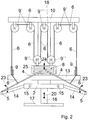
- the longitudinally displaceable along the direction of displacement 21 seat 3 via two parallel guide rods 15 is slidably supported on the base frame 2, wherein the seat 3 not shown guide elements such as ball slides smoothly slide on the guide rods 15. hereby Only little power of the rowing is needed for this adjustment of the seat 3.
- the rowers sitting on the seat 3 and show his legs in the direction of the front support 18, can be supported on the rudder device 1 with the legs, in the direction of displacement 21 in front of the range of movement of the seat 3 along the direction of displacement 21 adjustable and customizable diagonally flip-up footrest 19 is provided, on which the rowers as in rowing in a rowboat supported his feet when performing the rudder movement and so can move the seat 3 along the direction of displacement 21 by stretching and tightening the legs.
- a resistance device 8 Arranged at the front end of the base frame 2 on the support 18 is a resistance device 8, which is described below, which ensures that the rowing person experiences a resistance during the actuation of the rudder bars 4, which largely corresponds to the resistance of the oars of a real rowing boat gliding through the water ,
- This purpose is served by a stack of, for example, plate-shaped or disc-shaped weights 7, which can perform a lifting movement in the lifting direction 24 in a guide frame 11. Due to gravity, a lifting force is required to lift these weights 7 against gravity, which applies the rowing by tightening the rudder bars 4 towards his body. This corresponds to the resistance of the water, which the rower must muster in real rowing while pulling the rudder against the water.
- a resistance device 8 Arranged at the front end of the base frame 2 on the support 18 is a resistance device 8, which is described below, which ensures that the rowing person experiences a resistance during the actuation of the rudder
- the rudder bars 4 are connected by means of a pulling means 6 extending continuously between the rudder bars 4, such as a band or a chain or the like.
- This traction means 6 is articulated in the area of the rudder bars 4 and extends over different deflection rollers 9, 9 'into the region of the resistance device 8 and actuates there the stack of the weights 7.
- the two lower front guide rollers 9 about an approximately vertical axis in Anstellraum 22 rotatably on the lower crossbar 13th are attached. Due to the rotational movement of the articulation point of the traction means 6 on the rudder bars 4, the lower front guide rollers 9 can adapt to the circular movement of this articulation point of the traction means 6 to the rudder bars 4 to 6 safely lead the traction means can.
- Another burden of the rowing to improve the training can be applied, that the sliding movement of the seat 3 relative to the horizontal can be tilted.
- the sliding movement of the seat 3 relative to the horizontal can be tilted.
- a further or alternative increase in the load of the rowing with respect to the leg movements can be achieved that between seat 3 and 2 base frame in the FIG. 1 only schematically indicated loading device 26 is arranged such that the to be carried out by the rowing relative movement between the seat 3 and the base frame 2 can be executed only against an additional resistance.
- the loading device as in the FIG. 1 indicated an arrangement of elastically stretchable bands or the like.
- mechanical spring elements or pneumatic or hydraulic cylinders through which the additional resistance in the relative movement between the seat and the base frame is caused. So can like in the FIG.
- each left and right of the sliding seat 3 are arranged and biased between frame 2 and seat 3, that in the backward movement 21 of the seat 3 in the rowing motion 23 these bands must be stretched 26 and thereby an increased force must be applied by the rowing to move the seat 3 in the rowing movement 23 to the rear.
Landscapes
- Health & Medical Sciences (AREA)
- General Health & Medical Sciences (AREA)
- Physical Education & Sports Medicine (AREA)
- Cardiology (AREA)
- Vascular Medicine (AREA)
- Life Sciences & Earth Sciences (AREA)
- Biophysics (AREA)
- Orthopedic Medicine & Surgery (AREA)
- Rehabilitation Tools (AREA)
Claims (18)
- Dispositif (1) servant à réaliser un entraînement au rameur, présentant un ensemble d'un siège (3) disposé sur un châssis principal (2) pour une personne ramant et deux tiges de rameur (4) montées de manière rotative et pouvant être déplacées indépendamment l'une de l'autre, qui doivent être déplacées tout autour de leur palier rotatif (5) à l'encontre d'une résistance par la personne ramant lors de la réalisation du mouvement de rameur,
caractérisé en ce que
le siège (3) est disposé de manière à pouvoir coulisser sur le châssis principal (2) par rapport au palier (5) rotatif des tiges de rameur (4) et les tiges de rameur (4) sont reliées à un dispositif de résistance (8) composé d'un ensemble composé de poids (7) pouvant être montés et descendus au moyen d'un moyen de traction (6) s'étendant en continu entre les tiges de rameur (4), dans lequel le moyen de traction (6) est guidé de telle sorte que le mouvement de montée (24) des poids (7) est effectué, lors de la réalisation du mouvement de rameur, de manière plus lente et/ou sur une distance plus petite que le coulissement du moyen de traction (6) dans la zone des tiges de rameur (4). - Dispositif (1) selon la revendication 1, caractérisé en ce que les tiges de rameur (4) sont montées de manière à pouvoir tourner (5) au niveau de supports (14) dépassant à la manière d'une console du châssis principal (2) de manière latérale et transversale par rapport à la direction de coulissement (21) du siège (3), dans lequel de préférence les longueurs et l'ensemble du palier (5) rotatif des tiges de rameur (4) correspondent largement aux rapports cinématiques de l'aviron réel.
- Dispositif (1) selon l'une quelconque des revendications précédentes, caractérisé en ce que les axes du palier (5) des tiges de rameur (4) sont disposés de manière inclinée par rapport à la verticale pour permettre un mouvement des tiges de rameur (4) favorable sur le plan anatomique et correspondant largement aux rapports cinématiques de l'aviron réel.
- Dispositif (1) selon l'une quelconque des revendications précédentes, caractérisé en ce que le dispositif de résistance (8) est disposé au centre dans le prolongement du mouvement par coulissement (21) du siège (3) devant la personne ramant au niveau du châssis principal (2).
- Dispositif (1) selon l'une quelconque des revendications précédentes, caractérisé en ce que les moyens de traction (6) présentent des bandes ou des chaînes ou similaires, qui sont fixées de manière articulée au niveau des tiges de rameur (4), dans lequel les moyens de traction (6) peuvent être renvoyés de préférence depuis les tiges de rameur (4) en passant par des poulies de renvoi (9, 9') jusqu'au dispositif de résistance (8).
- Dispositif (1) selon l'une quelconque des revendications précédentes, caractérisé en ce qu'une bande ou similaire continue est prévue en tant que moyen de traction (6), laquelle s'étend depuis une tige de rameur (4) jusqu'à l'autre tige de rameur (4) en passant par les poulies de renvoi (9, 9', 9", 9''') et le dispositif de résistance (8).
- Dispositif (1) selon l'une quelconque des revendications précédentes, caractérisé en ce que le siège (3) est disposé de manière à pouvoir coulisser avec une mobilité aisée par rapport au châssis principal (2) par l'intermédiaire d'un palier lisse ou d'un palier à roulement, de préférence de manière montée sur des roulements au niveau de tiges de guidage (15), dans lequel le siège (3) est disposé de manière à pouvoir coulisser avec une mobilité aisée de préférence au niveau du châssis principal (2) de telle sorte que l'axe de coulissement (21) du siège (3) peut être réglé de manière inclinée horizontalement par rapport au châssis principal (2) et l'axe de coulissement (21) du siège (3) est disposé par rapport au châssis principal (2) de telle sorte que le siège (3) est disposé plus en hauteur dans sa position finale la plus éloignée de l'axe de rotation (5) des tiges de rameur (4) que dans sa position finale plus proche par rapport à l'axe de rotation (5) des tiges de rameur (4).
- Dispositif (1) selon la revendication 7, caractérisé en ce que le châssis principal (4) est réalisé de manière ajustable en hauteur (20) au niveau d'une extrémité, dans lequel l'ajustement en hauteur côté extrémité du châssis principal (2) fait pivoter conjointement l'axe de coulissement (21) du siège (3).
- Dispositif (1) selon l'une quelconque des revendications précédentes, caractérisé en ce qu'un appui-pied (19) pouvant être réglé de manière à pouvoir coulisser le long de l'axe de coulissement (21) du siège (3) peut être fixé au niveau du châssis principal (2), sur lequel la personne ramant prend appui lors de la réalisation du mouvement de rameur, dans lequel l'appui-pied (19) est disposé de préférence avec un angle ajustable au niveau du châssis principal (2).
- Dispositif (1) selon l'une quelconque des revendications précédentes, caractérisé en ce qu'un dispositif de contrainte (26) est disposé de telle manière entre le siège (3) et le châssis principal (2) que le mouvement relatif, à exécuter par la personne ramant, entre le siège (3) et le châssis principal (2) peut être exécuté seulement à l'encontre d'une résistance supplémentaire, dans lequel le système de contrainte (26) présente de préférence un ensemble de bandes élastiquement expansibles ou similaires et/ou d'éléments de ressort mécaniques et/ou de cylindres pneumatiques et/ou de cylindres hydrauliques, qui permettent de provoquer, de préférence de régler, la résistance supplémentaire lors du mouvement relatif entre le siège (3) et le châssis principal (2).
- Dispositif (1) selon l'une quelconque des revendications précédentes, caractérisé en ce que le dispositif de résistance (8) présente au moins trois poulies de renvoi (9", 9'''), dans lequel deux des poulies de renvoi (9") sont fixées de manière symétrique par rapport à l'axe de montée des poids (7) au niveau du dispositif de support (25) pouvant être soulevé des poids (7) et la troisième poulie de renvoi (9''') est disposée de manière stationnaire au centre au-dessus des deux poulies de renvoi (9"), de préférence de manière stationnaire rotative au niveau du châssis du dispositif (1).
- Dispositif (1) selon la revendication 11, caractérisé en ce que l'ensemble des poulies de renvoi (9, 9', 9", 9''') est réalisé de manière symétrique par rapport à l'axe de coulissement (21) du siège (3).
- Dispositif (1) selon l'une quelconque des revendications 11 ou 12, caractérisé en ce que le moyen de traction (6) s'étend depuis une tige de rameur (4) en passant par une poulie de renvoi (9) inférieure disposée de manière adjacente par rapport au point de rotation (5) de la tige de rameur (4) vers le haut vers une deuxième poulie de renvoi (9') disposée au-dessus, de là vers une troisième poulie de renvoi (9') disposée davantage à proximité au niveau du dispositif de résistance (8) et depuis ladite troisième poulie de renvoi (9') vers le bas vers une des deux poulies de renvoi (9") au niveau du dispositif de support (25) pouvant être relevé des poids (7).
- Dispositif (1) selon l'une quelconque des revendications 11 à 13, caractérisé en ce que le moyen de traction (6) s'étend dans la zone du dispositif de support (25) pouvant être relevé des poids (7) de telle manière que le moyen de traction (6) guidé vers le bas par la troisième poulie de renvoi (9') s'étend au-dessus de la première des deux poulies de renvoi (9") au niveau du dispositif de support (25) pouvant être relevé, de là à nouveau vers le haut vers la troisième poulie de renvoi (9"') stationnaire du dispositif de résistance (8), puis à nouveau vers la seconde des deux poulies de renvoi (9") au niveau du dispositif de support (25) pouvant être relevé.
- Dispositif (1) selon l'une quelconque des revendications 11 à 14, caractérisé en ce que les poulies de renvoi (9) disposées de manière adjacente par rapport aux points de rotation (5) des tiges de rameur (4) sont disposées de manière à pouvoir pivoter autour d'un axe vertical et s'orientent ainsi toujours de manière à s'adapter à la position du point d'articulation du moyen de traction (6) au niveau de la tige de rameur (4), ce pour quoi les poulies de renvoi (9) disposées de manière adjacente par rapport aux points de rotation (5) des tiges de rameur (4) sont disposées de manière à pouvoir tourner de préférence au niveau de bras (13) latéraux du châssis principal (2).
- Dispositif (1) selon l'une quelconque des revendications 11 à 15, caractérisé en ce que les poulies de renvoi (9') disposées en haut sont disposées de manière à pouvoir tourner au niveau de bras (10), orientés les uns par rapport aux autres en forme de V, du châssis principal (2).
- Dispositif (1) selon l'une quelconque des revendications précédentes, caractérisé en ce que le dispositif de support des poids (7) présente un dispositif de guidage (11), de préférence une ou plusieurs tiges, qui guide le mouvement de montée et de descente des poids (7).
- Dispositif (1) selon l'une quelconque des revendications précédentes, caractérisé en ce que des disques peuvent être emboîtés en tant que poids (7) sur le dispositif de support pouvant être relevé pour les poids (7) ou des plaques peuvent être prévues en tant que poids (7) sur le dispositif de support pouvant être relevé pour les poids (7), qui peuvent être couplées individuellement ou en piles au dispositif de support au moyen d'éléments d'enfichage.
Priority Applications (1)
| Application Number | Priority Date | Filing Date | Title |
|---|---|---|---|
| PL17001870T PL3323475T3 (pl) | 2016-11-17 | 2017-11-15 | Urządzenie do przeprowadzania treningu wioślarskiego |
Applications Claiming Priority (1)
| Application Number | Priority Date | Filing Date | Title |
|---|---|---|---|
| DE202016007143.3U DE202016007143U1 (de) | 2016-11-17 | 2016-11-17 | Einrichtung zur Durchführung eines Rudertrainings |
Publications (2)
| Publication Number | Publication Date |
|---|---|
| EP3323475A1 EP3323475A1 (fr) | 2018-05-23 |
| EP3323475B1 true EP3323475B1 (fr) | 2019-07-03 |
Family
ID=57582310
Family Applications (1)
| Application Number | Title | Priority Date | Filing Date |
|---|---|---|---|
| EP17001870.9A Active EP3323475B1 (fr) | 2016-11-17 | 2017-11-15 | Dispositif permettant d'effectuer un entraînement de gouvernail |
Country Status (3)
| Country | Link |
|---|---|
| EP (1) | EP3323475B1 (fr) |
| DE (1) | DE202016007143U1 (fr) |
| PL (1) | PL3323475T3 (fr) |
Families Citing this family (3)
| Publication number | Priority date | Publication date | Assignee | Title |
|---|---|---|---|---|
| CN111298409B (zh) * | 2020-02-28 | 2021-04-09 | 吉林师范大学 | 运动员体能的训练管理设备 |
| CN111714825B (zh) * | 2020-06-30 | 2021-05-07 | 嘉兴职业技术学院 | 一种趣味划船机 |
| CN111701187B (zh) * | 2020-06-30 | 2021-05-07 | 嘉兴职业技术学院 | 一种协同训练用划船机 |
Family Cites Families (5)
| Publication number | Priority date | Publication date | Assignee | Title |
|---|---|---|---|---|
| DE29705990U1 (de) | 1997-04-03 | 1998-09-17 | Gym 80 International, 45891 Gelsenkirchen | Rudermaschine |
| US7169093B2 (en) * | 1999-09-14 | 2007-01-30 | Free Motion Fitness, Inc. | Cable crossover exercise apparatus |
| US20060264128A1 (en) * | 2005-05-23 | 2006-11-23 | Osten Frederick F | Portable rowing/exercise device |
| WO2008141160A2 (fr) | 2007-05-11 | 2008-11-20 | D Eredita Michael | Machine à ramer simulée |
| US10065060B2 (en) * | 2014-04-15 | 2018-09-04 | Louie Simmons | Static-dynamic exercise apparatus and method of using same |
-
2016
- 2016-11-17 DE DE202016007143.3U patent/DE202016007143U1/de not_active Expired - Lifetime
-
2017
- 2017-11-15 EP EP17001870.9A patent/EP3323475B1/fr active Active
- 2017-11-15 PL PL17001870T patent/PL3323475T3/pl unknown
Non-Patent Citations (1)
| Title |
|---|
| None * |
Also Published As
| Publication number | Publication date |
|---|---|
| PL3323475T3 (pl) | 2019-12-31 |
| DE202016007143U1 (de) | 2016-11-30 |
| EP3323475A1 (fr) | 2018-05-23 |
Similar Documents
| Publication | Publication Date | Title |
|---|---|---|
| DE2417258C3 (de) | Übungsgerät | |
| DE3343387A1 (de) | Uebungsgeraet fuer bestimmte koerpermuskeln | |
| DE3807152A1 (de) | Gewichthebe-uebungseinrichtung | |
| EP3323475B1 (fr) | Dispositif permettant d'effectuer un entraînement de gouvernail | |
| DE3618954C1 (de) | Trainingsgeraet | |
| DE102016106413B4 (de) | Trainings- oder therapiegerät | |
| DE202008015084U1 (de) | Trainingsgerät | |
| EP3621704A1 (fr) | Appareil de fitness pour effectuer des exercices de type pompes | |
| DE202023100260U1 (de) | Trainingsgerät für mehrere Muskelgruppen | |
| WO2023139409A1 (fr) | Station d'entraînement musculaire destinée à la réalisation d'exercices de musculation par un utilisateur | |
| DE1174227B (de) | Gymnastikgeraet zur Ausfuehrung aktiver und passiver Bewegungen des Koerpers | |
| DE202021106943U1 (de) | Kraftstation zum Durchführen von Kraftübungen durch einen Nutzer | |
| DE202010018106U1 (de) | Vorrichtung zur Erzeugung eines hydrodynamischen Widerstands und Trainingsgerät mit einer solchen Vorrichtung | |
| LU603163B1 (de) | Ein unterstützendes Rehabilitationsgerät zur Behandlung von zerebrovaskulären Erkrankungen | |
| DE102013200094B4 (de) | Stationäres Trainingsgerät "Alltrainer" | |
| DE3613618C2 (fr) | ||
| DE19737441C2 (de) | Kraftstoffgerät zur Stärkung der Beinmuskulatur | |
| DE202005000866U1 (de) | Trainings- und/oder Rehabilitationsgerät | |
| DE202022001084U1 (de) | Multifunktionales Trainings- und/oder Rehabilitationsgerät | |
| DE102016100434A1 (de) | Fitnessgerät | |
| DD236877A1 (de) | Universaltrainingsgeraet | |
| DE202014006578U1 (de) | Alltrainer (S) - Stationäres Ganzkörpertrainingsgerät | |
| DE202009016809U1 (de) | Trainingsgerät mit einem Laufband | |
| DE20110516U1 (de) | Trainingsmaschine | |
| DE202012006702U1 (de) | Trainingsgerät für Paddelsportarten |
Legal Events
| Date | Code | Title | Description |
|---|---|---|---|
| PUAI | Public reference made under article 153(3) epc to a published international application that has entered the european phase |
Free format text: ORIGINAL CODE: 0009012 |
|
| STAA | Information on the status of an ep patent application or granted ep patent |
Free format text: STATUS: THE APPLICATION HAS BEEN PUBLISHED |
|
| AK | Designated contracting states |
Kind code of ref document: A1 Designated state(s): AL AT BE BG CH CY CZ DE DK EE ES FI FR GB GR HR HU IE IS IT LI LT LU LV MC MK MT NL NO PL PT RO RS SE SI SK SM TR |
|
| AX | Request for extension of the european patent |
Extension state: BA ME |
|
| STAA | Information on the status of an ep patent application or granted ep patent |
Free format text: STATUS: REQUEST FOR EXAMINATION WAS MADE |
|
| 17P | Request for examination filed |
Effective date: 20181119 |
|
| RBV | Designated contracting states (corrected) |
Designated state(s): AL AT BE BG CH CY CZ DE DK EE ES FI FR GB GR HR HU IE IS IT LI LT LU LV MC MK MT NL NO PL PT RO RS SE SI SK SM TR |
|
| GRAP | Despatch of communication of intention to grant a patent |
Free format text: ORIGINAL CODE: EPIDOSNIGR1 |
|
| STAA | Information on the status of an ep patent application or granted ep patent |
Free format text: STATUS: GRANT OF PATENT IS INTENDED |
|
| INTG | Intention to grant announced |
Effective date: 20190129 |
|
| GRAS | Grant fee paid |
Free format text: ORIGINAL CODE: EPIDOSNIGR3 |
|
| GRAA | (expected) grant |
Free format text: ORIGINAL CODE: 0009210 |
|
| STAA | Information on the status of an ep patent application or granted ep patent |
Free format text: STATUS: THE PATENT HAS BEEN GRANTED |
|
| AK | Designated contracting states |
Kind code of ref document: B1 Designated state(s): AL AT BE BG CH CY CZ DE DK EE ES FI FR GB GR HR HU IE IS IT LI LT LU LV MC MK MT NL NO PL PT RO RS SE SI SK SM TR |
|
| REG | Reference to a national code |
Ref country code: GB Ref legal event code: FG4D Free format text: NOT ENGLISH |
|
| REG | Reference to a national code |
Ref country code: AT Ref legal event code: REF Ref document number: 1150276 Country of ref document: AT Kind code of ref document: T Effective date: 20190715 Ref country code: CH Ref legal event code: EP |
|
| REG | Reference to a national code |
Ref country code: DE Ref legal event code: R096 Ref document number: 502017001652 Country of ref document: DE |
|
| REG | Reference to a national code |
Ref country code: IE Ref legal event code: FG4D Free format text: LANGUAGE OF EP DOCUMENT: GERMAN |
|
| REG | Reference to a national code |
Ref country code: NL Ref legal event code: MP Effective date: 20190703 |
|
| REG | Reference to a national code |
Ref country code: LT Ref legal event code: MG4D |
|
| PG25 | Lapsed in a contracting state [announced via postgrant information from national office to epo] |
Ref country code: HR Free format text: LAPSE BECAUSE OF FAILURE TO SUBMIT A TRANSLATION OF THE DESCRIPTION OR TO PAY THE FEE WITHIN THE PRESCRIBED TIME-LIMIT Effective date: 20190703 Ref country code: LT Free format text: LAPSE BECAUSE OF FAILURE TO SUBMIT A TRANSLATION OF THE DESCRIPTION OR TO PAY THE FEE WITHIN THE PRESCRIBED TIME-LIMIT Effective date: 20190703 Ref country code: PT Free format text: LAPSE BECAUSE OF FAILURE TO SUBMIT A TRANSLATION OF THE DESCRIPTION OR TO PAY THE FEE WITHIN THE PRESCRIBED TIME-LIMIT Effective date: 20191104 Ref country code: BG Free format text: LAPSE BECAUSE OF FAILURE TO SUBMIT A TRANSLATION OF THE DESCRIPTION OR TO PAY THE FEE WITHIN THE PRESCRIBED TIME-LIMIT Effective date: 20191003 Ref country code: NO Free format text: LAPSE BECAUSE OF FAILURE TO SUBMIT A TRANSLATION OF THE DESCRIPTION OR TO PAY THE FEE WITHIN THE PRESCRIBED TIME-LIMIT Effective date: 20191003 Ref country code: NL Free format text: LAPSE BECAUSE OF FAILURE TO SUBMIT A TRANSLATION OF THE DESCRIPTION OR TO PAY THE FEE WITHIN THE PRESCRIBED TIME-LIMIT Effective date: 20190703 Ref country code: SE Free format text: LAPSE BECAUSE OF FAILURE TO SUBMIT A TRANSLATION OF THE DESCRIPTION OR TO PAY THE FEE WITHIN THE PRESCRIBED TIME-LIMIT Effective date: 20190703 Ref country code: CZ Free format text: LAPSE BECAUSE OF FAILURE TO SUBMIT A TRANSLATION OF THE DESCRIPTION OR TO PAY THE FEE WITHIN THE PRESCRIBED TIME-LIMIT Effective date: 20190703 Ref country code: FI Free format text: LAPSE BECAUSE OF FAILURE TO SUBMIT A TRANSLATION OF THE DESCRIPTION OR TO PAY THE FEE WITHIN THE PRESCRIBED TIME-LIMIT Effective date: 20190703 |
|
| PG25 | Lapsed in a contracting state [announced via postgrant information from national office to epo] |
Ref country code: ES Free format text: LAPSE BECAUSE OF FAILURE TO SUBMIT A TRANSLATION OF THE DESCRIPTION OR TO PAY THE FEE WITHIN THE PRESCRIBED TIME-LIMIT Effective date: 20190703 Ref country code: LV Free format text: LAPSE BECAUSE OF FAILURE TO SUBMIT A TRANSLATION OF THE DESCRIPTION OR TO PAY THE FEE WITHIN THE PRESCRIBED TIME-LIMIT Effective date: 20190703 Ref country code: AL Free format text: LAPSE BECAUSE OF FAILURE TO SUBMIT A TRANSLATION OF THE DESCRIPTION OR TO PAY THE FEE WITHIN THE PRESCRIBED TIME-LIMIT Effective date: 20190703 Ref country code: GR Free format text: LAPSE BECAUSE OF FAILURE TO SUBMIT A TRANSLATION OF THE DESCRIPTION OR TO PAY THE FEE WITHIN THE PRESCRIBED TIME-LIMIT Effective date: 20191004 Ref country code: IS Free format text: LAPSE BECAUSE OF FAILURE TO SUBMIT A TRANSLATION OF THE DESCRIPTION OR TO PAY THE FEE WITHIN THE PRESCRIBED TIME-LIMIT Effective date: 20191103 Ref country code: RS Free format text: LAPSE BECAUSE OF FAILURE TO SUBMIT A TRANSLATION OF THE DESCRIPTION OR TO PAY THE FEE WITHIN THE PRESCRIBED TIME-LIMIT Effective date: 20190703 |
|
| PG25 | Lapsed in a contracting state [announced via postgrant information from national office to epo] |
Ref country code: TR Free format text: LAPSE BECAUSE OF FAILURE TO SUBMIT A TRANSLATION OF THE DESCRIPTION OR TO PAY THE FEE WITHIN THE PRESCRIBED TIME-LIMIT Effective date: 20190703 |
|
| PG25 | Lapsed in a contracting state [announced via postgrant information from national office to epo] |
Ref country code: RO Free format text: LAPSE BECAUSE OF FAILURE TO SUBMIT A TRANSLATION OF THE DESCRIPTION OR TO PAY THE FEE WITHIN THE PRESCRIBED TIME-LIMIT Effective date: 20190703 Ref country code: DK Free format text: LAPSE BECAUSE OF FAILURE TO SUBMIT A TRANSLATION OF THE DESCRIPTION OR TO PAY THE FEE WITHIN THE PRESCRIBED TIME-LIMIT Effective date: 20190703 Ref country code: EE Free format text: LAPSE BECAUSE OF FAILURE TO SUBMIT A TRANSLATION OF THE DESCRIPTION OR TO PAY THE FEE WITHIN THE PRESCRIBED TIME-LIMIT Effective date: 20190703 |
|
| PG25 | Lapsed in a contracting state [announced via postgrant information from national office to epo] |
Ref country code: SM Free format text: LAPSE BECAUSE OF FAILURE TO SUBMIT A TRANSLATION OF THE DESCRIPTION OR TO PAY THE FEE WITHIN THE PRESCRIBED TIME-LIMIT Effective date: 20190703 Ref country code: SK Free format text: LAPSE BECAUSE OF FAILURE TO SUBMIT A TRANSLATION OF THE DESCRIPTION OR TO PAY THE FEE WITHIN THE PRESCRIBED TIME-LIMIT Effective date: 20190703 Ref country code: IS Free format text: LAPSE BECAUSE OF FAILURE TO SUBMIT A TRANSLATION OF THE DESCRIPTION OR TO PAY THE FEE WITHIN THE PRESCRIBED TIME-LIMIT Effective date: 20200224 |
|
| REG | Reference to a national code |
Ref country code: DE Ref legal event code: R097 Ref document number: 502017001652 Country of ref document: DE |
|
| PLBE | No opposition filed within time limit |
Free format text: ORIGINAL CODE: 0009261 |
|
| STAA | Information on the status of an ep patent application or granted ep patent |
Free format text: STATUS: NO OPPOSITION FILED WITHIN TIME LIMIT |
|
| PG2D | Information on lapse in contracting state deleted |
Ref country code: IS |
|
| PG25 | Lapsed in a contracting state [announced via postgrant information from national office to epo] |
Ref country code: MC Free format text: LAPSE BECAUSE OF FAILURE TO SUBMIT A TRANSLATION OF THE DESCRIPTION OR TO PAY THE FEE WITHIN THE PRESCRIBED TIME-LIMIT Effective date: 20190703 Ref country code: LU Free format text: LAPSE BECAUSE OF NON-PAYMENT OF DUE FEES Effective date: 20191115 |
|
| 26N | No opposition filed |
Effective date: 20200603 |
|
| PG25 | Lapsed in a contracting state [announced via postgrant information from national office to epo] |
Ref country code: SI Free format text: LAPSE BECAUSE OF FAILURE TO SUBMIT A TRANSLATION OF THE DESCRIPTION OR TO PAY THE FEE WITHIN THE PRESCRIBED TIME-LIMIT Effective date: 20190703 |
|
| PG25 | Lapsed in a contracting state [announced via postgrant information from national office to epo] |
Ref country code: IE Free format text: LAPSE BECAUSE OF NON-PAYMENT OF DUE FEES Effective date: 20191115 |
|
| PG25 | Lapsed in a contracting state [announced via postgrant information from national office to epo] |
Ref country code: CY Free format text: LAPSE BECAUSE OF FAILURE TO SUBMIT A TRANSLATION OF THE DESCRIPTION OR TO PAY THE FEE WITHIN THE PRESCRIBED TIME-LIMIT Effective date: 20190703 |
|
| REG | Reference to a national code |
Ref country code: CH Ref legal event code: PL |
|
| PG25 | Lapsed in a contracting state [announced via postgrant information from national office to epo] |
Ref country code: MT Free format text: LAPSE BECAUSE OF FAILURE TO SUBMIT A TRANSLATION OF THE DESCRIPTION OR TO PAY THE FEE WITHIN THE PRESCRIBED TIME-LIMIT Effective date: 20190703 Ref country code: HU Free format text: LAPSE BECAUSE OF FAILURE TO SUBMIT A TRANSLATION OF THE DESCRIPTION OR TO PAY THE FEE WITHIN THE PRESCRIBED TIME-LIMIT; INVALID AB INITIO Effective date: 20171115 |
|
| REG | Reference to a national code |
Ref country code: DE Ref legal event code: R081 Ref document number: 502017001652 Country of ref document: DE Owner name: KNOKE, FRANK, DE Free format text: FORMER OWNER: F.D. FITNESS CONCEPT GMBH, 59368 WERNE, DE Ref country code: DE Ref legal event code: R081 Ref document number: 502017001652 Country of ref document: DE Owner name: HERMANSKI, SILVIA, DE Free format text: FORMER OWNER: F.D. FITNESS CONCEPT GMBH, 59368 WERNE, DE |
|
| PG25 | Lapsed in a contracting state [announced via postgrant information from national office to epo] |
Ref country code: CH Free format text: LAPSE BECAUSE OF NON-PAYMENT OF DUE FEES Effective date: 20201130 Ref country code: LI Free format text: LAPSE BECAUSE OF NON-PAYMENT OF DUE FEES Effective date: 20201130 |
|
| REG | Reference to a national code |
Ref country code: GB Ref legal event code: 732E Free format text: REGISTERED BETWEEN 20210902 AND 20210908 |
|
| REG | Reference to a national code |
Ref country code: BE Ref legal event code: PD Owner name: HERMANSKI, SILVIA; DE Free format text: DETAILS ASSIGNMENT: CHANGE OF OWNER(S), ASSIGNMENT; FORMER OWNER NAME: F.D. FITNESS CONCEPT GMBH Effective date: 20210813 |
|
| PGFP | Annual fee paid to national office [announced via postgrant information from national office to epo] |
Ref country code: FR Payment date: 20210831 Year of fee payment: 5 |
|
| PGFP | Annual fee paid to national office [announced via postgrant information from national office to epo] |
Ref country code: GB Payment date: 20211022 Year of fee payment: 5 |
|
| PGFP | Annual fee paid to national office [announced via postgrant information from national office to epo] |
Ref country code: IT Payment date: 20211103 Year of fee payment: 5 Ref country code: BE Payment date: 20211013 Year of fee payment: 5 |
|
| PGFP | Annual fee paid to national office [announced via postgrant information from national office to epo] |
Ref country code: PL Payment date: 20211012 Year of fee payment: 5 |
|
| PG25 | Lapsed in a contracting state [announced via postgrant information from national office to epo] |
Ref country code: MK Free format text: LAPSE BECAUSE OF FAILURE TO SUBMIT A TRANSLATION OF THE DESCRIPTION OR TO PAY THE FEE WITHIN THE PRESCRIBED TIME-LIMIT Effective date: 20190703 |
|
| REG | Reference to a national code |
Ref country code: DE Ref legal event code: R081 Ref document number: 502017001652 Country of ref document: DE Owner name: KNOKE, FRANK, DE Free format text: FORMER OWNER: HERMANSKI, SILVIA, 59425 UNNA, DE |
|
| GBPC | Gb: european patent ceased through non-payment of renewal fee |
Effective date: 20221115 |
|
| REG | Reference to a national code |
Ref country code: BE Ref legal event code: MM Effective date: 20221130 |
|
| PG25 | Lapsed in a contracting state [announced via postgrant information from national office to epo] |
Ref country code: IT Free format text: LAPSE BECAUSE OF NON-PAYMENT OF DUE FEES Effective date: 20221115 Ref country code: GB Free format text: LAPSE BECAUSE OF NON-PAYMENT OF DUE FEES Effective date: 20221115 |
|
| PG25 | Lapsed in a contracting state [announced via postgrant information from national office to epo] |
Ref country code: FR Free format text: LAPSE BECAUSE OF NON-PAYMENT OF DUE FEES Effective date: 20221130 Ref country code: BE Free format text: LAPSE BECAUSE OF NON-PAYMENT OF DUE FEES Effective date: 20221130 |
|
| REG | Reference to a national code |
Ref country code: AT Ref legal event code: MM01 Ref document number: 1150276 Country of ref document: AT Kind code of ref document: T Effective date: 20221115 |
|
| PG25 | Lapsed in a contracting state [announced via postgrant information from national office to epo] |
Ref country code: AT Free format text: LAPSE BECAUSE OF NON-PAYMENT OF DUE FEES Effective date: 20221115 |
|
| PG25 | Lapsed in a contracting state [announced via postgrant information from national office to epo] |
Ref country code: PL Free format text: LAPSE BECAUSE OF NON-PAYMENT OF DUE FEES Effective date: 20221115 |
|
| PGFP | Annual fee paid to national office [announced via postgrant information from national office to epo] |
Ref country code: DE Payment date: 20251008 Year of fee payment: 9 |