EP3323669B1 - Fahrzeugsteuergerät (vcu) und betriebsverfahren dafür - Google Patents
Fahrzeugsteuergerät (vcu) und betriebsverfahren dafür Download PDFInfo
- Publication number
- EP3323669B1 EP3323669B1 EP17202718.7A EP17202718A EP3323669B1 EP 3323669 B1 EP3323669 B1 EP 3323669B1 EP 17202718 A EP17202718 A EP 17202718A EP 3323669 B1 EP3323669 B1 EP 3323669B1
- Authority
- EP
- European Patent Office
- Prior art keywords
- vehicle
- speed
- point
- information
- vcu
- Prior art date
- Legal status (The legal status is an assumption and is not a legal conclusion. Google has not performed a legal analysis and makes no representation as to the accuracy of the status listed.)
- Active
Links
Images





Classifications
-
- B—PERFORMING OPERATIONS; TRANSPORTING
- B60—VEHICLES IN GENERAL
- B60W—CONJOINT CONTROL OF VEHICLE SUB-UNITS OF DIFFERENT TYPE OR DIFFERENT FUNCTION; CONTROL SYSTEMS SPECIALLY ADAPTED FOR HYBRID VEHICLES; ROAD VEHICLE DRIVE CONTROL SYSTEMS FOR PURPOSES NOT RELATED TO THE CONTROL OF A PARTICULAR SUB-UNIT
- B60W30/00—Purposes of road vehicle drive control systems not related to the control of a particular sub-unit, e.g. of systems using conjoint control of vehicle sub-units
- B60W30/18—Propelling the vehicle
-
- B—PERFORMING OPERATIONS; TRANSPORTING
- B60—VEHICLES IN GENERAL
- B60L—PROPULSION OF ELECTRICALLY-PROPELLED VEHICLES; SUPPLYING ELECTRIC POWER FOR AUXILIARY EQUIPMENT OF ELECTRICALLY-PROPELLED VEHICLES; ELECTRODYNAMIC BRAKE SYSTEMS FOR VEHICLES IN GENERAL; MAGNETIC SUSPENSION OR LEVITATION FOR VEHICLES; MONITORING OPERATING VARIABLES OF ELECTRICALLY-PROPELLED VEHICLES; ELECTRIC SAFETY DEVICES FOR ELECTRICALLY-PROPELLED VEHICLES
- B60L15/00—Methods, circuits, or devices for controlling the traction-motor speed of electrically-propelled vehicles
- B60L15/20—Methods, circuits, or devices for controlling the traction-motor speed of electrically-propelled vehicles for control of the vehicle or its driving motor to achieve a desired performance, e.g. speed, torque, programmed variation of speed
-
- B—PERFORMING OPERATIONS; TRANSPORTING
- B60—VEHICLES IN GENERAL
- B60L—PROPULSION OF ELECTRICALLY-PROPELLED VEHICLES; SUPPLYING ELECTRIC POWER FOR AUXILIARY EQUIPMENT OF ELECTRICALLY-PROPELLED VEHICLES; ELECTRODYNAMIC BRAKE SYSTEMS FOR VEHICLES IN GENERAL; MAGNETIC SUSPENSION OR LEVITATION FOR VEHICLES; MONITORING OPERATING VARIABLES OF ELECTRICALLY-PROPELLED VEHICLES; ELECTRIC SAFETY DEVICES FOR ELECTRICALLY-PROPELLED VEHICLES
- B60L15/00—Methods, circuits, or devices for controlling the traction-motor speed of electrically-propelled vehicles
- B60L15/20—Methods, circuits, or devices for controlling the traction-motor speed of electrically-propelled vehicles for control of the vehicle or its driving motor to achieve a desired performance, e.g. speed, torque, programmed variation of speed
- B60L15/2045—Methods, circuits, or devices for controlling the traction-motor speed of electrically-propelled vehicles for control of the vehicle or its driving motor to achieve a desired performance, e.g. speed, torque, programmed variation of speed for optimising the use of energy
-
- B—PERFORMING OPERATIONS; TRANSPORTING
- B60—VEHICLES IN GENERAL
- B60L—PROPULSION OF ELECTRICALLY-PROPELLED VEHICLES; SUPPLYING ELECTRIC POWER FOR AUXILIARY EQUIPMENT OF ELECTRICALLY-PROPELLED VEHICLES; ELECTRODYNAMIC BRAKE SYSTEMS FOR VEHICLES IN GENERAL; MAGNETIC SUSPENSION OR LEVITATION FOR VEHICLES; MONITORING OPERATING VARIABLES OF ELECTRICALLY-PROPELLED VEHICLES; ELECTRIC SAFETY DEVICES FOR ELECTRICALLY-PROPELLED VEHICLES
- B60L50/00—Electric propulsion with power supplied within the vehicle
- B60L50/50—Electric propulsion with power supplied within the vehicle using propulsion power supplied by batteries or fuel cells
-
- B—PERFORMING OPERATIONS; TRANSPORTING
- B60—VEHICLES IN GENERAL
- B60L—PROPULSION OF ELECTRICALLY-PROPELLED VEHICLES; SUPPLYING ELECTRIC POWER FOR AUXILIARY EQUIPMENT OF ELECTRICALLY-PROPELLED VEHICLES; ELECTRODYNAMIC BRAKE SYSTEMS FOR VEHICLES IN GENERAL; MAGNETIC SUSPENSION OR LEVITATION FOR VEHICLES; MONITORING OPERATING VARIABLES OF ELECTRICALLY-PROPELLED VEHICLES; ELECTRIC SAFETY DEVICES FOR ELECTRICALLY-PROPELLED VEHICLES
- B60L50/00—Electric propulsion with power supplied within the vehicle
- B60L50/50—Electric propulsion with power supplied within the vehicle using propulsion power supplied by batteries or fuel cells
- B60L50/60—Electric propulsion with power supplied within the vehicle using propulsion power supplied by batteries or fuel cells using power supplied by batteries
-
- B—PERFORMING OPERATIONS; TRANSPORTING
- B60—VEHICLES IN GENERAL
- B60L—PROPULSION OF ELECTRICALLY-PROPELLED VEHICLES; SUPPLYING ELECTRIC POWER FOR AUXILIARY EQUIPMENT OF ELECTRICALLY-PROPELLED VEHICLES; ELECTRODYNAMIC BRAKE SYSTEMS FOR VEHICLES IN GENERAL; MAGNETIC SUSPENSION OR LEVITATION FOR VEHICLES; MONITORING OPERATING VARIABLES OF ELECTRICALLY-PROPELLED VEHICLES; ELECTRIC SAFETY DEVICES FOR ELECTRICALLY-PROPELLED VEHICLES
- B60L58/00—Methods or circuit arrangements for monitoring or controlling batteries or fuel cells, specially adapted for electric vehicles
- B60L58/10—Methods or circuit arrangements for monitoring or controlling batteries or fuel cells, specially adapted for electric vehicles for monitoring or controlling batteries
- B60L58/12—Methods or circuit arrangements for monitoring or controlling batteries or fuel cells, specially adapted for electric vehicles for monitoring or controlling batteries responding to state of charge [SoC]
- B60L58/13—Maintaining the SoC within a determined range
-
- B—PERFORMING OPERATIONS; TRANSPORTING
- B60—VEHICLES IN GENERAL
- B60L—PROPULSION OF ELECTRICALLY-PROPELLED VEHICLES; SUPPLYING ELECTRIC POWER FOR AUXILIARY EQUIPMENT OF ELECTRICALLY-PROPELLED VEHICLES; ELECTRODYNAMIC BRAKE SYSTEMS FOR VEHICLES IN GENERAL; MAGNETIC SUSPENSION OR LEVITATION FOR VEHICLES; MONITORING OPERATING VARIABLES OF ELECTRICALLY-PROPELLED VEHICLES; ELECTRIC SAFETY DEVICES FOR ELECTRICALLY-PROPELLED VEHICLES
- B60L58/00—Methods or circuit arrangements for monitoring or controlling batteries or fuel cells, specially adapted for electric vehicles
- B60L58/10—Methods or circuit arrangements for monitoring or controlling batteries or fuel cells, specially adapted for electric vehicles for monitoring or controlling batteries
- B60L58/12—Methods or circuit arrangements for monitoring or controlling batteries or fuel cells, specially adapted for electric vehicles for monitoring or controlling batteries responding to state of charge [SoC]
- B60L58/14—Preventing excessive discharging
-
- B—PERFORMING OPERATIONS; TRANSPORTING
- B60—VEHICLES IN GENERAL
- B60W—CONJOINT CONTROL OF VEHICLE SUB-UNITS OF DIFFERENT TYPE OR DIFFERENT FUNCTION; CONTROL SYSTEMS SPECIALLY ADAPTED FOR HYBRID VEHICLES; ROAD VEHICLE DRIVE CONTROL SYSTEMS FOR PURPOSES NOT RELATED TO THE CONTROL OF A PARTICULAR SUB-UNIT
- B60W30/00—Purposes of road vehicle drive control systems not related to the control of a particular sub-unit, e.g. of systems using conjoint control of vehicle sub-units
- B60W30/18—Propelling the vehicle
- B60W30/188—Controlling power parameters of the driveline, e.g. determining the required power
- B60W30/1886—Controlling power supply to auxiliary devices
-
- B—PERFORMING OPERATIONS; TRANSPORTING
- B60—VEHICLES IN GENERAL
- B60W—CONJOINT CONTROL OF VEHICLE SUB-UNITS OF DIFFERENT TYPE OR DIFFERENT FUNCTION; CONTROL SYSTEMS SPECIALLY ADAPTED FOR HYBRID VEHICLES; ROAD VEHICLE DRIVE CONTROL SYSTEMS FOR PURPOSES NOT RELATED TO THE CONTROL OF A PARTICULAR SUB-UNIT
- B60W40/00—Estimation or calculation of non-directly measurable driving parameters for road vehicle drive control systems not related to the control of a particular sub unit, e.g. by using mathematical models
- B60W40/10—Estimation or calculation of non-directly measurable driving parameters for road vehicle drive control systems not related to the control of a particular sub unit, e.g. by using mathematical models related to vehicle motion
- B60W40/105—Speed
-
- B—PERFORMING OPERATIONS; TRANSPORTING
- B60—VEHICLES IN GENERAL
- B60W—CONJOINT CONTROL OF VEHICLE SUB-UNITS OF DIFFERENT TYPE OR DIFFERENT FUNCTION; CONTROL SYSTEMS SPECIALLY ADAPTED FOR HYBRID VEHICLES; ROAD VEHICLE DRIVE CONTROL SYSTEMS FOR PURPOSES NOT RELATED TO THE CONTROL OF A PARTICULAR SUB-UNIT
- B60W50/00—Details of control systems for road vehicle drive control not related to the control of a particular sub-unit, e.g. process diagnostic or vehicle driver interfaces
- B60W50/08—Interaction between the driver and the control system
- B60W50/14—Means for informing the driver, warning the driver or prompting a driver intervention
-
- B—PERFORMING OPERATIONS; TRANSPORTING
- B60—VEHICLES IN GENERAL
- B60L—PROPULSION OF ELECTRICALLY-PROPELLED VEHICLES; SUPPLYING ELECTRIC POWER FOR AUXILIARY EQUIPMENT OF ELECTRICALLY-PROPELLED VEHICLES; ELECTRODYNAMIC BRAKE SYSTEMS FOR VEHICLES IN GENERAL; MAGNETIC SUSPENSION OR LEVITATION FOR VEHICLES; MONITORING OPERATING VARIABLES OF ELECTRICALLY-PROPELLED VEHICLES; ELECTRIC SAFETY DEVICES FOR ELECTRICALLY-PROPELLED VEHICLES
- B60L2240/00—Control parameters of input or output; Target parameters
- B60L2240/10—Vehicle control parameters
- B60L2240/12—Speed
-
- B—PERFORMING OPERATIONS; TRANSPORTING
- B60—VEHICLES IN GENERAL
- B60L—PROPULSION OF ELECTRICALLY-PROPELLED VEHICLES; SUPPLYING ELECTRIC POWER FOR AUXILIARY EQUIPMENT OF ELECTRICALLY-PROPELLED VEHICLES; ELECTRODYNAMIC BRAKE SYSTEMS FOR VEHICLES IN GENERAL; MAGNETIC SUSPENSION OR LEVITATION FOR VEHICLES; MONITORING OPERATING VARIABLES OF ELECTRICALLY-PROPELLED VEHICLES; ELECTRIC SAFETY DEVICES FOR ELECTRICALLY-PROPELLED VEHICLES
- B60L2240/00—Control parameters of input or output; Target parameters
- B60L2240/10—Vehicle control parameters
- B60L2240/14—Acceleration
-
- B—PERFORMING OPERATIONS; TRANSPORTING
- B60—VEHICLES IN GENERAL
- B60L—PROPULSION OF ELECTRICALLY-PROPELLED VEHICLES; SUPPLYING ELECTRIC POWER FOR AUXILIARY EQUIPMENT OF ELECTRICALLY-PROPELLED VEHICLES; ELECTRODYNAMIC BRAKE SYSTEMS FOR VEHICLES IN GENERAL; MAGNETIC SUSPENSION OR LEVITATION FOR VEHICLES; MONITORING OPERATING VARIABLES OF ELECTRICALLY-PROPELLED VEHICLES; ELECTRIC SAFETY DEVICES FOR ELECTRICALLY-PROPELLED VEHICLES
- B60L2240/00—Control parameters of input or output; Target parameters
- B60L2240/60—Navigation input
- B60L2240/64—Road conditions
- B60L2240/645—Type of road
-
- B—PERFORMING OPERATIONS; TRANSPORTING
- B60—VEHICLES IN GENERAL
- B60L—PROPULSION OF ELECTRICALLY-PROPELLED VEHICLES; SUPPLYING ELECTRIC POWER FOR AUXILIARY EQUIPMENT OF ELECTRICALLY-PROPELLED VEHICLES; ELECTRODYNAMIC BRAKE SYSTEMS FOR VEHICLES IN GENERAL; MAGNETIC SUSPENSION OR LEVITATION FOR VEHICLES; MONITORING OPERATING VARIABLES OF ELECTRICALLY-PROPELLED VEHICLES; ELECTRIC SAFETY DEVICES FOR ELECTRICALLY-PROPELLED VEHICLES
- B60L2240/00—Control parameters of input or output; Target parameters
- B60L2240/60—Navigation input
- B60L2240/66—Ambient conditions
- B60L2240/662—Temperature
-
- B—PERFORMING OPERATIONS; TRANSPORTING
- B60—VEHICLES IN GENERAL
- B60L—PROPULSION OF ELECTRICALLY-PROPELLED VEHICLES; SUPPLYING ELECTRIC POWER FOR AUXILIARY EQUIPMENT OF ELECTRICALLY-PROPELLED VEHICLES; ELECTRODYNAMIC BRAKE SYSTEMS FOR VEHICLES IN GENERAL; MAGNETIC SUSPENSION OR LEVITATION FOR VEHICLES; MONITORING OPERATING VARIABLES OF ELECTRICALLY-PROPELLED VEHICLES; ELECTRIC SAFETY DEVICES FOR ELECTRICALLY-PROPELLED VEHICLES
- B60L2240/00—Control parameters of input or output; Target parameters
- B60L2240/60—Navigation input
- B60L2240/66—Ambient conditions
- B60L2240/667—Precipitation
-
- B—PERFORMING OPERATIONS; TRANSPORTING
- B60—VEHICLES IN GENERAL
- B60L—PROPULSION OF ELECTRICALLY-PROPELLED VEHICLES; SUPPLYING ELECTRIC POWER FOR AUXILIARY EQUIPMENT OF ELECTRICALLY-PROPELLED VEHICLES; ELECTRODYNAMIC BRAKE SYSTEMS FOR VEHICLES IN GENERAL; MAGNETIC SUSPENSION OR LEVITATION FOR VEHICLES; MONITORING OPERATING VARIABLES OF ELECTRICALLY-PROPELLED VEHICLES; ELECTRIC SAFETY DEVICES FOR ELECTRICALLY-PROPELLED VEHICLES
- B60L2240/00—Control parameters of input or output; Target parameters
- B60L2240/60—Navigation input
- B60L2240/68—Traffic data
-
- B—PERFORMING OPERATIONS; TRANSPORTING
- B60—VEHICLES IN GENERAL
- B60L—PROPULSION OF ELECTRICALLY-PROPELLED VEHICLES; SUPPLYING ELECTRIC POWER FOR AUXILIARY EQUIPMENT OF ELECTRICALLY-PROPELLED VEHICLES; ELECTRODYNAMIC BRAKE SYSTEMS FOR VEHICLES IN GENERAL; MAGNETIC SUSPENSION OR LEVITATION FOR VEHICLES; MONITORING OPERATING VARIABLES OF ELECTRICALLY-PROPELLED VEHICLES; ELECTRIC SAFETY DEVICES FOR ELECTRICALLY-PROPELLED VEHICLES
- B60L2250/00—Driver interactions
- B60L2250/16—Driver interactions by display
-
- B—PERFORMING OPERATIONS; TRANSPORTING
- B60—VEHICLES IN GENERAL
- B60L—PROPULSION OF ELECTRICALLY-PROPELLED VEHICLES; SUPPLYING ELECTRIC POWER FOR AUXILIARY EQUIPMENT OF ELECTRICALLY-PROPELLED VEHICLES; ELECTRODYNAMIC BRAKE SYSTEMS FOR VEHICLES IN GENERAL; MAGNETIC SUSPENSION OR LEVITATION FOR VEHICLES; MONITORING OPERATING VARIABLES OF ELECTRICALLY-PROPELLED VEHICLES; ELECTRIC SAFETY DEVICES FOR ELECTRICALLY-PROPELLED VEHICLES
- B60L2260/00—Operating Modes
- B60L2260/20—Drive modes; Transition between modes
- B60L2260/32—Auto pilot mode
-
- B—PERFORMING OPERATIONS; TRANSPORTING
- B60—VEHICLES IN GENERAL
- B60L—PROPULSION OF ELECTRICALLY-PROPELLED VEHICLES; SUPPLYING ELECTRIC POWER FOR AUXILIARY EQUIPMENT OF ELECTRICALLY-PROPELLED VEHICLES; ELECTRODYNAMIC BRAKE SYSTEMS FOR VEHICLES IN GENERAL; MAGNETIC SUSPENSION OR LEVITATION FOR VEHICLES; MONITORING OPERATING VARIABLES OF ELECTRICALLY-PROPELLED VEHICLES; ELECTRIC SAFETY DEVICES FOR ELECTRICALLY-PROPELLED VEHICLES
- B60L2260/00—Operating Modes
- B60L2260/40—Control modes
- B60L2260/44—Control modes by parameter estimation
-
- B—PERFORMING OPERATIONS; TRANSPORTING
- B60—VEHICLES IN GENERAL
- B60L—PROPULSION OF ELECTRICALLY-PROPELLED VEHICLES; SUPPLYING ELECTRIC POWER FOR AUXILIARY EQUIPMENT OF ELECTRICALLY-PROPELLED VEHICLES; ELECTRODYNAMIC BRAKE SYSTEMS FOR VEHICLES IN GENERAL; MAGNETIC SUSPENSION OR LEVITATION FOR VEHICLES; MONITORING OPERATING VARIABLES OF ELECTRICALLY-PROPELLED VEHICLES; ELECTRIC SAFETY DEVICES FOR ELECTRICALLY-PROPELLED VEHICLES
- B60L2260/00—Operating Modes
- B60L2260/40—Control modes
- B60L2260/48—Control modes by fuzzy logic
-
- B—PERFORMING OPERATIONS; TRANSPORTING
- B60—VEHICLES IN GENERAL
- B60L—PROPULSION OF ELECTRICALLY-PROPELLED VEHICLES; SUPPLYING ELECTRIC POWER FOR AUXILIARY EQUIPMENT OF ELECTRICALLY-PROPELLED VEHICLES; ELECTRODYNAMIC BRAKE SYSTEMS FOR VEHICLES IN GENERAL; MAGNETIC SUSPENSION OR LEVITATION FOR VEHICLES; MONITORING OPERATING VARIABLES OF ELECTRICALLY-PROPELLED VEHICLES; ELECTRIC SAFETY DEVICES FOR ELECTRICALLY-PROPELLED VEHICLES
- B60L2260/00—Operating Modes
- B60L2260/40—Control modes
- B60L2260/50—Control modes by future state prediction
- B60L2260/52—Control modes by future state prediction drive range estimation, e.g. of estimation of available travel distance
-
- B—PERFORMING OPERATIONS; TRANSPORTING
- B60—VEHICLES IN GENERAL
- B60L—PROPULSION OF ELECTRICALLY-PROPELLED VEHICLES; SUPPLYING ELECTRIC POWER FOR AUXILIARY EQUIPMENT OF ELECTRICALLY-PROPELLED VEHICLES; ELECTRODYNAMIC BRAKE SYSTEMS FOR VEHICLES IN GENERAL; MAGNETIC SUSPENSION OR LEVITATION FOR VEHICLES; MONITORING OPERATING VARIABLES OF ELECTRICALLY-PROPELLED VEHICLES; ELECTRIC SAFETY DEVICES FOR ELECTRICALLY-PROPELLED VEHICLES
- B60L2260/00—Operating Modes
- B60L2260/40—Control modes
- B60L2260/50—Control modes by future state prediction
- B60L2260/54—Energy consumption estimation
-
- B—PERFORMING OPERATIONS; TRANSPORTING
- B60—VEHICLES IN GENERAL
- B60W—CONJOINT CONTROL OF VEHICLE SUB-UNITS OF DIFFERENT TYPE OR DIFFERENT FUNCTION; CONTROL SYSTEMS SPECIALLY ADAPTED FOR HYBRID VEHICLES; ROAD VEHICLE DRIVE CONTROL SYSTEMS FOR PURPOSES NOT RELATED TO THE CONTROL OF A PARTICULAR SUB-UNIT
- B60W2510/00—Input parameters relating to a particular sub-units
- B60W2510/09—Other types of propulsion units, e.g. fluid motors, or type not specified
-
- B—PERFORMING OPERATIONS; TRANSPORTING
- B60—VEHICLES IN GENERAL
- B60W—CONJOINT CONTROL OF VEHICLE SUB-UNITS OF DIFFERENT TYPE OR DIFFERENT FUNCTION; CONTROL SYSTEMS SPECIALLY ADAPTED FOR HYBRID VEHICLES; ROAD VEHICLE DRIVE CONTROL SYSTEMS FOR PURPOSES NOT RELATED TO THE CONTROL OF A PARTICULAR SUB-UNIT
- B60W2510/00—Input parameters relating to a particular sub-units
- B60W2510/30—Auxiliary equipments
- B60W2510/305—Power absorbed by auxiliaries
-
- B—PERFORMING OPERATIONS; TRANSPORTING
- B60—VEHICLES IN GENERAL
- B60W—CONJOINT CONTROL OF VEHICLE SUB-UNITS OF DIFFERENT TYPE OR DIFFERENT FUNCTION; CONTROL SYSTEMS SPECIALLY ADAPTED FOR HYBRID VEHICLES; ROAD VEHICLE DRIVE CONTROL SYSTEMS FOR PURPOSES NOT RELATED TO THE CONTROL OF A PARTICULAR SUB-UNIT
- B60W2520/00—Input parameters relating to overall vehicle dynamics
- B60W2520/10—Longitudinal speed
-
- B—PERFORMING OPERATIONS; TRANSPORTING
- B60—VEHICLES IN GENERAL
- B60W—CONJOINT CONTROL OF VEHICLE SUB-UNITS OF DIFFERENT TYPE OR DIFFERENT FUNCTION; CONTROL SYSTEMS SPECIALLY ADAPTED FOR HYBRID VEHICLES; ROAD VEHICLE DRIVE CONTROL SYSTEMS FOR PURPOSES NOT RELATED TO THE CONTROL OF A PARTICULAR SUB-UNIT
- B60W2530/00—Input parameters relating to vehicle conditions or values, not covered by groups B60W2510/00 or B60W2520/00
- B60W2530/209—Fuel quantity remaining in tank
-
- B—PERFORMING OPERATIONS; TRANSPORTING
- B60—VEHICLES IN GENERAL
- B60W—CONJOINT CONTROL OF VEHICLE SUB-UNITS OF DIFFERENT TYPE OR DIFFERENT FUNCTION; CONTROL SYSTEMS SPECIALLY ADAPTED FOR HYBRID VEHICLES; ROAD VEHICLE DRIVE CONTROL SYSTEMS FOR PURPOSES NOT RELATED TO THE CONTROL OF A PARTICULAR SUB-UNIT
- B60W2552/00—Input parameters relating to infrastructure
- B60W2552/05—Type of road, e.g. motorways, local streets, paved or unpaved roads
-
- B—PERFORMING OPERATIONS; TRANSPORTING
- B60—VEHICLES IN GENERAL
- B60W—CONJOINT CONTROL OF VEHICLE SUB-UNITS OF DIFFERENT TYPE OR DIFFERENT FUNCTION; CONTROL SYSTEMS SPECIALLY ADAPTED FOR HYBRID VEHICLES; ROAD VEHICLE DRIVE CONTROL SYSTEMS FOR PURPOSES NOT RELATED TO THE CONTROL OF A PARTICULAR SUB-UNIT
- B60W2554/00—Input parameters relating to objects
-
- B—PERFORMING OPERATIONS; TRANSPORTING
- B60—VEHICLES IN GENERAL
- B60W—CONJOINT CONTROL OF VEHICLE SUB-UNITS OF DIFFERENT TYPE OR DIFFERENT FUNCTION; CONTROL SYSTEMS SPECIALLY ADAPTED FOR HYBRID VEHICLES; ROAD VEHICLE DRIVE CONTROL SYSTEMS FOR PURPOSES NOT RELATED TO THE CONTROL OF A PARTICULAR SUB-UNIT
- B60W2554/00—Input parameters relating to objects
- B60W2554/40—Dynamic objects, e.g. animals, windblown objects
- B60W2554/406—Traffic density
-
- B—PERFORMING OPERATIONS; TRANSPORTING
- B60—VEHICLES IN GENERAL
- B60W—CONJOINT CONTROL OF VEHICLE SUB-UNITS OF DIFFERENT TYPE OR DIFFERENT FUNCTION; CONTROL SYSTEMS SPECIALLY ADAPTED FOR HYBRID VEHICLES; ROAD VEHICLE DRIVE CONTROL SYSTEMS FOR PURPOSES NOT RELATED TO THE CONTROL OF A PARTICULAR SUB-UNIT
- B60W2555/00—Input parameters relating to exterior conditions, not covered by groups B60W2552/00, B60W2554/00
- B60W2555/20—Ambient conditions, e.g. wind or rain
-
- B—PERFORMING OPERATIONS; TRANSPORTING
- B60—VEHICLES IN GENERAL
- B60W—CONJOINT CONTROL OF VEHICLE SUB-UNITS OF DIFFERENT TYPE OR DIFFERENT FUNCTION; CONTROL SYSTEMS SPECIALLY ADAPTED FOR HYBRID VEHICLES; ROAD VEHICLE DRIVE CONTROL SYSTEMS FOR PURPOSES NOT RELATED TO THE CONTROL OF A PARTICULAR SUB-UNIT
- B60W2720/00—Output or target parameters relating to overall vehicle dynamics
- B60W2720/10—Longitudinal speed
-
- B—PERFORMING OPERATIONS; TRANSPORTING
- B60—VEHICLES IN GENERAL
- B60W—CONJOINT CONTROL OF VEHICLE SUB-UNITS OF DIFFERENT TYPE OR DIFFERENT FUNCTION; CONTROL SYSTEMS SPECIALLY ADAPTED FOR HYBRID VEHICLES; ROAD VEHICLE DRIVE CONTROL SYSTEMS FOR PURPOSES NOT RELATED TO THE CONTROL OF A PARTICULAR SUB-UNIT
- B60W2720/00—Output or target parameters relating to overall vehicle dynamics
- B60W2720/10—Longitudinal speed
- B60W2720/103—Speed profile
-
- Y—GENERAL TAGGING OF NEW TECHNOLOGICAL DEVELOPMENTS; GENERAL TAGGING OF CROSS-SECTIONAL TECHNOLOGIES SPANNING OVER SEVERAL SECTIONS OF THE IPC; TECHNICAL SUBJECTS COVERED BY FORMER USPC CROSS-REFERENCE ART COLLECTIONS [XRACs] AND DIGESTS
- Y02—TECHNOLOGIES OR APPLICATIONS FOR MITIGATION OR ADAPTATION AGAINST CLIMATE CHANGE
- Y02T—CLIMATE CHANGE MITIGATION TECHNOLOGIES RELATED TO TRANSPORTATION
- Y02T10/00—Road transport of goods or passengers
- Y02T10/60—Other road transportation technologies with climate change mitigation effect
- Y02T10/64—Electric machine technologies in electromobility
-
- Y—GENERAL TAGGING OF NEW TECHNOLOGICAL DEVELOPMENTS; GENERAL TAGGING OF CROSS-SECTIONAL TECHNOLOGIES SPANNING OVER SEVERAL SECTIONS OF THE IPC; TECHNICAL SUBJECTS COVERED BY FORMER USPC CROSS-REFERENCE ART COLLECTIONS [XRACs] AND DIGESTS
- Y02—TECHNOLOGIES OR APPLICATIONS FOR MITIGATION OR ADAPTATION AGAINST CLIMATE CHANGE
- Y02T—CLIMATE CHANGE MITIGATION TECHNOLOGIES RELATED TO TRANSPORTATION
- Y02T10/00—Road transport of goods or passengers
- Y02T10/60—Other road transportation technologies with climate change mitigation effect
- Y02T10/70—Energy storage systems for electromobility, e.g. batteries
-
- Y—GENERAL TAGGING OF NEW TECHNOLOGICAL DEVELOPMENTS; GENERAL TAGGING OF CROSS-SECTIONAL TECHNOLOGIES SPANNING OVER SEVERAL SECTIONS OF THE IPC; TECHNICAL SUBJECTS COVERED BY FORMER USPC CROSS-REFERENCE ART COLLECTIONS [XRACs] AND DIGESTS
- Y02—TECHNOLOGIES OR APPLICATIONS FOR MITIGATION OR ADAPTATION AGAINST CLIMATE CHANGE
- Y02T—CLIMATE CHANGE MITIGATION TECHNOLOGIES RELATED TO TRANSPORTATION
- Y02T10/00—Road transport of goods or passengers
- Y02T10/60—Other road transportation technologies with climate change mitigation effect
- Y02T10/72—Electric energy management in electromobility
-
- Y—GENERAL TAGGING OF NEW TECHNOLOGICAL DEVELOPMENTS; GENERAL TAGGING OF CROSS-SECTIONAL TECHNOLOGIES SPANNING OVER SEVERAL SECTIONS OF THE IPC; TECHNICAL SUBJECTS COVERED BY FORMER USPC CROSS-REFERENCE ART COLLECTIONS [XRACs] AND DIGESTS
- Y02—TECHNOLOGIES OR APPLICATIONS FOR MITIGATION OR ADAPTATION AGAINST CLIMATE CHANGE
- Y02T—CLIMATE CHANGE MITIGATION TECHNOLOGIES RELATED TO TRANSPORTATION
- Y02T90/00—Enabling technologies or technologies with a potential or indirect contribution to GHG emissions mitigation
- Y02T90/10—Technologies relating to charging of electric vehicles
- Y02T90/16—Information or communication technologies improving the operation of electric vehicles
Definitions
- VCU vehicle control unit
- An electric vehicle generates a speed profile based on a current driving speed.
- the speed profile generated by such a calculation does not consider ambient environment information of the electric vehicle and traffic information.
- the generated speed profile is greatly different from an actual driving speed profile of the electric vehicle.
- US 2016/176309 A1 relates to an apparatus for estimating a state of charge (SOC) of a battery in an electric vehicle.
- the apparatus may include a driving history data storage configured to store driving history data for each category among categories generated based on a frequency of appearance of road data, a driving profile generator configured to categorize road data associated with a driving route for each of the generated categories and generate a driving profile with respect to the driving route based on the driving history data corresponding to the categorized road data, and a battery SOC estimator configured to estimate the SOC of a the battery with respect to the driving route based on the driving profile.
- a driving history data storage configured to store driving history data for each category among categories generated based on a frequency of appearance of road data
- a driving profile generator configured to categorize road data associated with a driving route for each of the generated categories and generate a driving profile with respect to the driving route based on the driving history data corresponding to the categorized road data
- a battery SOC estimator configured to estimate the SOC of
- JP 2010 052652 A relates to a control device of a hybrid car and the energy arithmetic device of the vehicle for suitably performing energy control of a self-vehicle.
- the control device 10A of the hybrid car is provided with: an information acquisition means which acquires external information including the amounts of the variation of the speed of a vehicle traveling in the traveling section of a traveling scheduled path; an average speed in traveling of the vehicle which has traveled in the traveling section and an average gradient in the traveling section; a traveling energy arithmetic part and a vehicle tendency correction part which calculate the traveling energy in the traveling section, by using the external information and the preliminarily set parameter of a self-vehicle corresponding to each external information; and an EV upper-limit output value setting part for setting an EV upper-limit output value for making it possible for the vehicle to travel only by a motor 12 in the traveling section by using the traveling energy
- EP 2 792 551 A1 relates to improving the accuracy of prediction of the power consumption of the air conditioner units
- VCU vehicle control unit
- the calculating step of claim 1 includes calculating a speed variation corresponding to each point on a path of the vehicle based on respective input information associated with the each point.
- the input information includes any one or any combination of any two or more of weather information, traffic flow information, or road type information.
- the predicting step of claim 1 includes predicting an average speed of the vehicle at each point on a path of the vehicle based on a speed variation corresponding to the each point and a reference speed of the each point.
- the generating of the first speed profile of claim 1 includes generating the first speed profile based on an average speed predicted for each point on a path of the vehicle.
- the method may further include predicting an amount of power to be used by the vehicle based on the second speed profile.
- the method may further include predicting an amount of power to be transferred to a powertrain of the vehicle based on the second speed profile, and predicting an amount of power to be used by an air conditioning system of the vehicle based on either one or both of solar radiation information or ambient temperature information.
- the method may further include determining a driving range of the vehicle based on a predicted amount of power to be used by the vehicle and either one or both of current state information of a battery of the vehicle or a current amount of fuel of the vehicle.
- the determining may include predicting either one or both of state information of the battery or an amount of fuel at a destination based on the predicted amount of power to be used by the vehicle, and determining whether the vehicle is able to reach the destination based on either one or both of the predicted state information or the predicted amount of fuel.
- the method may further include generating guide information related to driving of the vehicle based on the second speed profile, and outputting the guide information to a user of the vehicle.
- the generating of the guide information may include comparing a predicted average speed determined from the second speed profile to a target speed determined from driving history information of the vehicle, and generating the guide information based on a result of the comparing.
- the generating of the guide information may include identifying a speed section satisfying a predetermined criterion in the second speed profile, and generating the guide information related to driving on a path corresponding to the identified speed section.
- a VCU including a processor configured to calculate a speed variation of a vehicle based on input information, predict an average speed of the vehicle based on the calculated speed variation, generate a first speed profile based on the predicted average speed, and generate a second speed profile according to further features of claim 8.
- the VCU may further include a memory configured to store instructions, and the processor may be further configured to execute the instructions to configure the processor to calculate the speed variation of the vehicle based on the input information, predict the average speed of the vehicle based on the calculated speed variation, generate the first speed profile based on the predicted average speed, and generate the second speed profile according to further features of claim 8.
- the processor may be configured to calculate a speed variation corresponding to each point on a path of the vehicle based on input information associated with the each point.
- the processor may be configured to predict an average speed of the vehicle at each point on a path of the vehicle based on a speed variation corresponding to the each point and a reference speed of the each point.
- the processor may be configured to generate the first speed profile based on an average speed predicted for each point on a path of the vehicle.
- the processor may be configured to predict an amount of power to be used by the vehicle based on the second speed profile.
- the processor may be configured to predict an amount of power to be transferred to a powertrain of the vehicle based on the second speed profile, and to predict an amount of power to be used by an air conditioning system of the vehicle based on either one or both of solar radiation information or ambient temperature information.
- the processor may be configured to determine a driving range of the vehicle based on a predicted amount of power to be used by the vehicle and either one or both of current state information of a battery of the vehicle or a current amount of fuel of the vehicle.
- the processor may be configured to predict either one or both of state information of the battery or an amount of fuel at a destination based on the predicted amount of power to be used by the vehicle, and to determine whether the vehicle is able to reach the destination based on either one or both of the predicted state information or the predicted amount of fuel.
- the processor may be configured to generate guide information related to driving of the vehicle based on the second speed profile, and to output the guide information to a user of the vehicle.
- the processor may be configured to compare a predicted average speed determined from the second speed profile to a target speed determined from driving history information of the vehicle, and to generate the guide information based on a comparison result.
- the processor may be configured to identify a speed section satisfying a predetermined criterion in the second speed profile, and to generate the guide information related to driving on a path corresponding to the identified speed section.
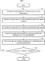
- FIG. 1 is a flowchart illustrating an example of an operation of a vehicle control unit (VCU), in accordance with an embodiment.
- VCU vehicle control unit
- a VCU calculates a speed variation of a vehicle based on input information.
- the VCU calculates a speed variation corresponding to each point on a path on which the vehicle is to be driven based on input information related to each point on the path.
- the input information includes, for example, weather information, traffic flow information, and road type information.
- the speed variation is calculated through a speed variation calculation model.
- the speed variation will be described further with reference to FIG. 2 .
- the VCU predicts an average speed of the vehicle based on the calculated speed variation.
- the VCU predicts an average speed of the vehicle at each point on the path based on a speed variation corresponding to the each point and reference speed information of the each point. For example, the VCU predicts the average speed of the vehicle at each point as "speed variation corresponding to each point + reference speed of each point". If the speed variation corresponding to each point and/or the reference speed of each point differs, the average speed of the vehicle at each point will be different.
- the VCU In operation 130, the VCU generates a first speed profile based on the predicted average speed.
- the VCU generates a first speed profile with respect to the path based on the average speed predicted with respect to each point on the path. Since the first speed profile is generated based on the predicted average speed, the first speed profile may not represent acceleration and/or deceleration of the vehicle accurately.
- the VCU may generate speed noise information through a noise generation function.
- the noise generation function is, for example, a Gaussian function with respect to additive white Gaussian noise (AWGN).
- AWGN additive white Gaussian noise
- the noise generation function is not limited thereto.
- the VCU In operation 140, the VCU generates a second speed profile by applying speed noise information to the first speed profile.
- the speed noise information may be information to represent acceleration and/or deceleration of the vehicle.
- the second speed profile more realistically represents acceleration and/or deceleration of the vehicle similar to an actual speed profile reflecting acceleration and/or deceleration of the vehicle.
- the VCU determines driving related information of the vehicle based on the second speed profile. For example, the VCU predicts an amount of power to be used by the vehicle to reach a destination (or an amount of power required for the vehicle to reach the destination) based on the second speed profile. Accordingly, the prediction accuracy with respect to the amount of power to be used by the vehicle is increased. The amount of power to be used by the vehicle will be described further with reference to FIGS. 5 and 6 .
- the VCU generates guide information related to driving of the vehicle based on the second speed profile. Thus, the VCU enables a user to use the vehicle more efficiently and to use a battery for a longer time. The guide information will be described further with reference to FIG. 7 .
- the VCU determines whether driving of the vehicle is completed, such as by determining whether the vehicle has reached a destination.
- the VCU operates based on an update period. That is, when the update period arrives, the VCU performs operations 110 through 150.
- the update period is modifiable, and the VCU performs operations 110 through 150 at an update request from the user.
- the VCU terminates its operation.
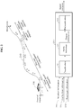
- FIG. 2 illustrates an example of calculating a speed variation by a VCU, in accordance with an embodiment.
- a path 210 and a vehicle 220 are illustrated.
- a VCU (not shown) in the vehicle 220 obtains input information related to each of points, for example, x, x+1, x+2, ... , and N, on the path 210.
- the input information includes, for example, one of weather information 230, traffic flow information 231, or road type information 232, or a combination thereof.
- the VCU obtains the weather information 230 of each point on the path 210, the traffic flow information 231 of each point on the path 210, and the road type information 232 corresponding to each point.
- the weather information 230, the traffic flow information 231, and the road type information 232 will be described below.
- the weather information 230 includes precipitation information P.
- the VCU receives precipitation information of each point on the path 210 from an external server, for example, a weather service center server or a precipitation information providing server, through a communication interface.
- the traffic flow information 231 includes a traffic index T determined based on a traffic congestion level of the path 210 and a delay time.
- the VCU receives the traffic congestion level of the path 210 and the delay time from the external server, for example, a traffic information providing server, through the communication interface.
- the VCU determines the traffic index T based on the traffic congestion level and the delay time.
- the VCU receives a traffic congestion level of each point on the path 210 and a delay time, and determines a traffic index T with respect to each point based on the traffic congestion level of each point and the delay time.
- the traffic index T is a value within a predetermined range, for example, between 0 and 10.
- the VCU determines a traffic index T with respect to the point x to be "4" by referring to a lookup table.
- the VCU receives the traffic index T with respect to each point on the path 210 from the external server.
- the road type information 232 indicates a road type R to which each point on the path 210 belongs.
- Road types include, for example, a street, a local road, and a freeway. However, the road types are not limited thereto. In the example of FIG. 2 , a road corresponding to the point x is a street, and a road corresponding to a point x+1 is a freeway.
- the VCU receives the road type information 232 from a navigation system of the vehicle.
- the weather information 230, the traffic flow information 231, and the road type information 232 are expressed as P, T, and R, respectively.
- the speed variation calculation model 240 of FIG. 2 is a fuzzy inference system based model.
- the speed variation calculation model 240 is not limited thereto, and may be a model trained through machine learning.
- the speed variation calculation model 240 may be based on a neural network model, a recurrent neural network (RNN) model, or a long short term memory (LSTM) RNN model.
- RNN recurrent neural network
- LSTM long short term memory
- the speed variation calculation model 240 performs a fuzzification 241 on P, T, and R of each point on the path 210 through membership functions of P, T, and R of each point on the path 210.
- the fuzzification 241 will be described further with reference to FIGS. 3A through 3C .
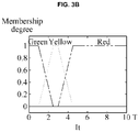
- FIGS. 3A through 3C are graphs illustrating examples of membership functions, in accordance with an embodiment.
- Equation 1 The membership function of P is expressed by, for example, Equation 1.
- T The membership function of T is expressed by, for example, Equation 2.
- GR clear traffic
- YW indicates mild traffic
- RD indicates heavy traffic.
- the speed variation calculation model 240 performs a fuzzy inference 242 based on the results of the fuzzification 241 with respect to P, T, and R of each point on the path 210, fuzzy rules, and output membership functions.
- the output membership functions are, for example, Gaussian functions. Equation 4 is an example of the output membership functions. However, the output membership functions are not limited to Equation 4. f x
- m , ⁇ 1 ⁇ 2 ⁇ e ⁇ x ⁇ m 2 2 ⁇ 2
- Equation 4 x is a variable. m and ⁇ are constants.
- the number of the output membership functions corresponds to the number of the fuzzy rules.
- the number of the output membership functions with respect to the 18 fuzzy rules of Table 1 is 18, as expressed below. ⁇ lc 1, lc 2, lc 3, lc 4, lc 5, lc 6, st 1, st 2, st 3 ,st 4 ,st 5, st 6, fw 1, fw 2, fw 3, fw 4, fw 5, fw 6 ⁇
- the speed variation calculation model 240 performs the fuzzy inference 242 by applying a Mamdani type method to the results of the fuzzification 241 with respect to P, T, and R of each point on the path 210, the fuzzy rules, and the output membership functions.
- the Mamdani type method is only an example of the fuzzy inference 242, and the fuzzy inference 242 is not limited thereto.
- Output information corresponding to the results of the fuzzification 241 is generated through the fuzzy inference 242.
- the speed variation calculation model 240 performs a defuzzification 243 on the output information.
- the speed variation calculation model 240 performs the defuzzification 243 on the output information through a center of gravity.
- the center of gravity is only an example of the defuzzification 243, and the defuzzification 243 is not limited thereto.
- the speed variation calculation model 240 calculates a speed variation corresponding to each point on the path 210 by performing the defuzzification 243 on the output information.
- the VCU determines the speed variation corresponding to each point on the path 210 to be a positive value or a negative value, by referring to driving history information of the vehicle.
- the driving history information includes, for example, a driving pattern and a previous speed profile. For example, the VCU determines whether a driver mostly drives at a low speed, for example, 20 kilometers per hour (km/h) to 50 km/h or at a medium speed, for example, 50 km/h to 70km/h, through the driving history information. If the driver mostly drives at the low speed or the medium speed, the VCU determines the speed variation to be a negative number. If the driver mostly drives at a high speed, for example, greater than 70 km/h, the VCU determines the speed variation to be a positive number.
- Table 2 shows examples of input information related to each point on the path 210 and a speed variation corresponding to each point on the path 210.
- the VCU determines the speed variation corresponding to each point on the path 210 to be a negative value.
- the VCU generates a first speed profile based on the speed variation corresponding to each point on the path 210, and generates a second speed profile by applying speed noise information to the first speed profile.
- a first speed profile based on the speed variation corresponding to each point on the path 210
- a second speed profile by applying speed noise information to the first speed profile.
- FIG. 4 illustrates an example of generating a first speed profile and a second speed profile by a VCU, in accordance with an embodiment.
- a path 410 and a vehicle 420 are illustrated.
- a VCU predicts an average speed of the vehicle 420 at each point on the path 410 based on a speed variation corresponding to each point on the path 410 and a reference speed of each point on the path 410.
- Table 3 shows an example of the average speed predicted with respect to each point on the path 410.
- the VCU generates a first speed profile 430 based on the average speed predicted with respect to each point on the path 410.
- the VCU generates a second speed profile 440 by applying speed noise information to the first speed profile 430.
- Traffic flow information of the point x+6 indicates congestion.
- the VCU obtains input information including the traffic flow information of the point x+6 at a current position of the vehicle 420
- the VCU calculates the speed variation of each point. For instance, the VCU calculates the speed variation of the point x+6 at -90km/h based on the traffic flow information of the point x+6.
- the VCU predicts the average speed of the vehicle 420 at each point.
- the VCU predicts an average speed at the point x+6 at 20km/h.
- the VCU generates the first speed profile 430 based on the average speed predicted with respect to each point, and generates the second speed profile 440 by applying the speed noise information to the first speed profile 430.
- the second speed profile 440 reflects real-time traffic flow information.
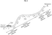
- FIGS. 5 and 6 illustrate examples of driving related information generated based on a second speed profile, in accordance with an embodiment.
- An example of driving related information indicates an amount of power to be used by a vehicle during driving.
- the amount of power to be used by the vehicle during driving includes E PT ( t ) and/or E HVAC ( t ).
- E PT ( t ) denotes a predicted amount of power to be transferred from a battery pack of the vehicle to a powertrain during driving of the vehicle
- E HVAC ( t ) denotes a predicted amount of power to be used by an air conditioning system of the vehicle during driving of the vehicle.
- the amount of power to be used by the vehicle during driving may additionally be calculated with respect to further variables, such as a predicted amount of power to be used by windshield wipers, a predicted amount of power to be used by a heating system of the vehicle, or a predicted amount of power used by the vehicle in consideration of a use of cruise control during driving.
- E PT ( t ) will be described with reference to FIG. 5
- E HVAC ( t ) will be described with reference to FIG. 6 .
- a vehicle 520 is driven along a path 510.
- the VCU calculates E PT ( t ) based on a second speed profile. For example, the VCU calculates E PT ( t ) by applying the second speed profile to a power consumption calculation function. That is, the VCU predicts an amount of power to be used by the vehicle 520 for driving from the current point x to a destination as E PT ( t ).
- the power consumption calculation function will be described below.
- the VCU calculates E PT ( t ) further based on a predicted value with respect to at least one of a wind direction, a wind speed, or an altitude of a following point.
- a predicted value with respect to the wind direction and the wind speed of the following point is calculated based on wind direction information and wind speed information of the current point, and a predicted value with respect to the altitude of the following point is calculated based on altitude information of the current point.
- the VCU calculates E PT ( t ) as expressed by, for example, Equation 5.
- Equation 5 g i,t denotes a speed of a vehicle at a following point i, calculated at a time t. That is, g i,t denotes the second speed profile described above. ⁇ i,t denotes a predicted value with respect to a wind direction and a wind speed of the following point i, calculated at the time t. ⁇ l i,t denotes a predicted value with respect to an altitude of the following point i, calculated at the time t. f i , t pt denotes a power consumption calculation function. For example, f i , t pt denotes a function to calculate an amount of power to be transferred to a powertrain in a section between a current point i-1 and the following point i.
- the VCU calculates, at a point x, at least one of a wind direction (predicted value), a wind speed (predicted value), or an altitude (predicted value) of a point x+1.
- the VCU calculates a predicted amount of power to be transferred to the powertrain in a section between the point x and the point x+1 by applying a speed (predicted value) of the vehicle at the point x+1 and at least one of the wind direction (predicted value), the wind speed (predicted value), or the altitude (predicted value) of the point x+1 to f i , t pt . .
- the VCU calculates a predicted amount of power to be transferred to the powertrain, with respect to another section.
- the VCU calculates E PT ( t ) by summing up the predicted values calculated with respect to respective sections, for example, between x and x+1, x+1 and x+2, ... , N-1 and N.
- the VCU further considers various variables to increase the accuracy of E PT ( t ).
- the VCU calculates E PT ( t ) as expressed by Equation 6.
- u x s L x F x C x W x P x S x
- Table 4 shows descriptions of variables and functions of Equation 6.
- speed related information u x s at the current point x includes a reference speed L x at the current point x, a driving speed F x of the vehicle 520 at the current point x, a precipitation C x of the current point x, a wind speed/wind direction W x of the current point x, an amount of instant power P x transferred to the powertrain at the current point x, and a state of charge (SOC) S x at the current point x.
- the speed related information is not limited thereto.
- u x s may include any one or any combination of two or more of the reference speed at the current point x, the driving speed of the vehicle 520 at the current point x, the precipitation of the current point x, the wind speed/wind direction of the current point x, the amount of instant power transferred to the powertrain at the current point x, or the SOC at the current point x.
- û i , t s denotes a predicted value calculated at a current time T with respect to speed related information at the following point i.
- û i , t s includes a predicted value calculated at the time t with respect to at least one of a precipitation of the following point i, a driving speed of the vehicle 520 at the following point i, a wind speed/wind direction of the following point i, an amount of instant power to be transferred to the powertrain at the following point i, or an SOC at the following point i.
- Equation 6 it includes at least one of information in û i , t s or information in û i , t w which will be described with reference to FIG. 6 .
- driving records stored for each road type and each driver are used to calculate a predicted value with respect to a speed of the vehicle 520 at the following point i.
- the VCU stores the driving records of the vehicle 520 for each road type, and generates a driving record function h c () for each road type.
- the VCU generates a driving record function with respect to a street, a driving record function with respect to a freeway, and a driving record function with respect to a local road.
- the VCU stores driving records of the vehicle 520 for each driver, and generates a driving record function h p () for each driver.
- the VCU uses h c () and h p () to calculate a predicted value with respect to the speed of the vehicle 520 at the following point i.
- Equation 6 ⁇ i,t denotes a predicted wind speed/wind direction calculated at a current time T at the point i, and ⁇ l i,t denotes a prediction altitude calculated at a current time T at the point i.
- the VCU calculates a predicted value with respect to the speed of the vehicle 520 at the following point i, that is, the point x+1 by applying the speed related information u x s at the point x, the predicted value û i , t s with respect to the speed related information at the point x+1, driving records with respect to a freeway to which the point x+1 belongs, and the driving records with respect to a current driver to g i.t (). Since the various variables are applied to g i.t (), the speed of the vehicle 520 at the point x+1 may be predicted more accurately.
- the VCU calculates a predicted amount of power to be transferred to the powertrain in a section between x and x+1 by applying the predicted value with respect to the speed of the vehicle 520 at the point x+1 and at least one of the wind direction (predicted value), the wind speed (predicted value), or the altitude (predicted value) at the point x+1 to f i , t pt .
- the VCU calculates a predicted amount of power to be transferred to the powertrain with respect to another section.
- the VCU calculates E PT ( t ) by summing up predicted values calculated with respect to respective sections, for example, between x and x+1, x+1 and x+2, ... , N-1 and N.
- E PT ( t ) is calculated in view of various environment variables, and thus the accuracy of E PT ( t ) increases.
- the vehicle 520 may operate an air conditioning system. As the air conditioning system is operated, an amount of power to be used by the vehicle 520 increases. Thus, if E HVAC ( t ), an amount of power to be used by the air conditioning system during driving of the vehicle 520, is predicted, the prediction accuracy with respect to the amount of power to be used by the vehicle 520 further increases.
- E HVAC ( t ) an amount of power to be used by the air conditioning system during driving of the vehicle 520
- a vehicle 610 and the sun 620 are illustrated.
- the VCU calculates E HVAC ( t ) based on at least one of solar radiation information or ambient temperature information. For example, the VCU calculates a predicted value with respect to weather related information of a following point, for example, a point x+1, based on weather related information of the current point x, and calculates E HVAC ( t ) based on the weather related information of the current point x and the predicted value with respect to the weather related information of the following point x+1.
- the weather related information includes, for example, ambient temperature, and an azimuth and solar radiation of the sun 620.
- the VCU calculates E HVAC ( t ) as expressed by, for example, Equation 7.
- Table 5 represents descriptions of variables and a function of Equation 7.
- Table 5 Description T i Ambient temperature of point i R i Solar azimuth and radiation amount at point i u i w
- f i , t aux denotes an auxiliary power consumption calculation function.
- f i , t aux is a function to calculate a predicted value with respect to an amount of auxiliary power to be used in a section between a point i-1 and a point i, for example, an amount of power to be used by the air conditioning system.
- the VCU calculates the predicted amount of power to be used by the air conditioning system in the section between x and x+1 by applying ambient temperature of the vehicle 610 at the point x, an azimuth of the sun 620 at the point x, an amount of solar radiation at the point x, ambient temperature (predicted value) of the vehicle 610 at the point x+1, an azimuth (predicted value) of the sun 620 at the point x+1, and an amount of solar radiation (predicted value) at the point x+1 to f i , t aux .
- the VCU calculates a predicted value with respect to an amount of power to be used by the air conditioning system with respect to another section.
- the VCU calculates E HVAC ( t ) by summing up predicted values with respect to respective sections, for example, between x and x+1, x+1 and x+2, ..., N-1 and N.
- the VCU further considers heat generated in a cabin of the vehicle 610 to increase the accuracy of E HVAC ( t ), which will be described further below.
- Heat is generated in the cabin of the vehicle 610 by various causes.
- heat is generated in the cabin of the vehicle 610 by at least one of direct solar radiation, diffuse solar radiation, reflected solar radiation, an ambient environment of the vehicle 610, ventilation 630, or a person 640, for example, a driver and/or a passenger.
- Table 6 lists types of heat generated in the cabin of the vehicle 610 and Q ⁇ .
- the cabin temperature (or the temperature of driver seat) is determined based on Equation 8.
- m ⁇ C room ⁇ dT dt Q ⁇ 1 + Q ⁇ 2 + Q ⁇ 3 + Q ⁇ 4 T + Q ⁇ 5 T + Q ⁇ 6
- Equation 8 m denotes a mass of the air, and C room denotes a specific heat of the air.
- Equation 8 If a heat transfer efficiency is considered in Equation 8, an amount of power or energy required to maintain an optimal cabin temperature is deduced.
- the deduced amount of power represents E HVAC ( t ) .
- the VCU predicts the amount of power to be used by the vehicle 610 as E PT ( t )+ E HVAC ( t ). That is, the VCU predicts an amount of power to be used by the vehicle 610 for driving from the current point x to a destination as E PT ( t )+ E HVAC ( t ).
- the VCU determines a driving range of the vehicle 610 based on the predicted amount of power.
- the predicted amount of power corresponds to E PT ( t ) or E PT ( t )+ E HVAC ( t ).
- the predicted amount of power is not limited thereto.
- an example of determining the driving range of the vehicle 610 will be described.
- the VCU determines the driving range of the vehicle 610 based on the predicted amount of power and current state information, for example, an SOC, of a battery.
- the VCU predicts an SOC at a destination by deducting an SOC corresponding to the predicted amount of the power from the current SOC. In other words, the VCU predicts a residual SOC corresponding to an SOC when the vehicle 610 reaches the destination. If the SOC at the destination is less than a predetermined criterion, for example, a value within 0 to 1%, the VCU determines that the vehicle 610 is unable to reach the destination with the current SOC. In this example, the VCU displays information related to a charging station located on a path through a display of the vehicle 610.
- the VCU displays a message indicating that the vehicle 610 is able to reach the destination with the current SOC on the display. Further, if the SOC at the destination is greater than or equal to the predetermined criterion, the VCU determines whether the vehicle 610 is able to perform a round trip with the current SOC. If the vehicle 610 is unable to perform a round trip with the current SOC, the VCU displays information related to a charging station located on a return path through the display.
- the VCU predicts an amount of fuel to be used by the vehicle 610 based on a second speed profile.
- the VCU determines the driving range of the vehicle 610 based on the predicted amount of fuel and a current amount of fuel. For example, the VCU predicts an amount of fuel at the destination by deducting the predicted amount of fuel from the current amount of fuel. If the amount of fuel at the destination is less than a predetermined criterion, for example, a value within 0 to 1 liter (L), the VCU determines that the vehicle 610 is unable to reach the destination with the current amount of fuel.
- a predetermined criterion for example, a value within 0 to 1 liter (L)
- the VCU displays a message indicating refueling is required and/or gas station information, for example, gas station location information, on the display. If the amount of fuel at the destination is greater than or equal to the predetermined criterion, the VCU determines whether the vehicle 610 is able to perform a round trip with the current amount of fuel. If the vehicle 610 is unable to perform a round trip with the current amount of fuel, the VCU displays information related to a gas station located on a return path through the display.
- FIG. 7 illustrates an example of driving related information generated based on a second speed profile, in accordance with an embodiment.
- driving related information is guide information related to driving.
- a VCU generates guide information 710 based on a second speed profile, and displays the guide information 710 on a display.
- the VCU deduces a predicted average speed in a section following a current driving section from the second speed profile. For example, when a vehicle is currently being driven in a first section of a freeway, the VCU deduces a predicted average speed in a section following the first section of the freeway from the second speed profile. Referring to the example of FIG. 4 , when the vehicle is driven in a section between x+1 and x+2 of the freeway, the VCU deduces a predicted average speed in a section, for example, between x+2 and x+3 or between x+2 and x+6, following the section between x+1 and x+2.
- the VCU deduces a target speed with respect to the current driving section from driving history information, for example, a previous speed profile, a charge and discharge count of a battery, and an accident history. For example, the VCU deduces a target speed with respect to the freeway through the driving history information. The VCU compares the predicted average speed to the target speed. If the predicted average speed is greater than the target speed, the VCU generates guide information 710 including information related to speed decrease and the target speed. If the predicted average speed is less than or equal to the target speed, the VCU generates guide information 710 related to maintenance of the current driving speed.
- driving history information for example, a previous speed profile, a charge and discharge count of a battery, and an accident history.
- driving history information for example, a previous speed profile, a charge and discharge count of a battery, and an accident history.
- the VCU deduces a target speed with respect to the freeway through the driving history information.
- the VCU compares the predicted average speed to the target speed. If the predicted
- the VCU identifies a speed section satisfying a predetermined criterion in the second speed profile.
- the speed section satisfying the predetermined criterion includes, for example, a speed section that influences a battery life.
- a deterioration speed of the battery life accelerates by sudden acceleration and/or sudden deceleration of the vehicle.
- the speed section that influences the battery life is a section in which sudden acceleration or sudden deceleration of the vehicle is expected.
- the speed section that influences the battery life is not limited thereto.
- the VCU generates guide information 710 related to driving on a path corresponding to the identified speed section. For example, the VCU displays guide information 710 indicating that safe driving is needed on the path corresponding to the identified speed section through a display.
- the VCU guides driving suitable for a battery life state.
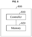
- FIG. 8 is a block diagram illustrating an example of a VCU in accordance with an embodiment.
- a VCU 800 includes a controller 810 and a memory 820.
- the controller 810 calculates a speed variation of a vehicle based on input information.
- the controller 810 predicts an average speed of the vehicle based on the calculated speed variation.
- the controller 810 generates a first speed profile based on the predicted average speed.
- the controller 810 generates a second speed profile by applying speed noise information to the first speed profile.
- the memory 820 stores at least one instruction associated with the operation of the controller 810. Further, the memory 820 stores the speed variation calculation model 240 of FIG. 2 .
- the apparatuses, units, modules, devices, controllers, and other components in FIG. 8 that perform the operations described in this application are implemented by hardware components configured to perform the operations described in this application that are performed by the hardware components.
- hardware components that may be used to perform the operations described in this application where appropriate include controllers, sensors, generators, drivers, memories, comparators, arithmetic logic units, adders, subtractors, multipliers, dividers, integrators, and any other electronic components configured to perform the operations described in this application.
- one or more of the hardware components that perform the operations described in this application are implemented by computing hardware, for example, by one or more processors or computers.
- a processor or computer may be implemented by one or more processing elements, such as an array of logic gates, a controller and an arithmetic logic unit, a digital signal processor, a microcomputer, a programmable logic controller, a field-programmable gate array, a programmable logic array, a microprocessor, or any other device or combination of devices that is configured to respond to and execute instructions in a defined manner to achieve a desired result.
- a processor or computer includes, or is connected to, one or more memories storing instructions or software that are executed by the processor or computer.
- Hardware components implemented by a processor or computer may execute instructions or software, such as an operating system (OS) and one or more software applications that run on the OS, to perform the operations described in this application.
- OS operating system
- the hardware components may also access, manipulate, process, create, and store data in response to execution of the instructions or software.
- processor or “computer” may be used in the description of the examples described in this application, but in other examples multiple processors or computers may be used, or a processor or computer may include multiple processing elements, or multiple types of processing elements, or both.
- a single hardware component or two or more hardware components may be implemented by a single processor, or two or more processors, or a processor and a controller.
- One or more hardware components may be implemented by one or more processors, or a processor and a controller, and one or more other hardware components may be implemented by one or more other processors, or another processor and another controller.
- One or more processors may implement a single hardware component, or two or more hardware components.
- a hardware component may have any one or more of different processing configurations, examples of which include a single processor, independent processors, parallel processors, single-instruction single-data (SISD) multiprocessing, single-instruction multiple-data (SIMD) multiprocessing, multiple-instruction single-data (MISD) multiprocessing, and multiple-instruction multiple-data (MIMD) multiprocessing.
- SISD single-instruction single-data
- SIMD single-instruction multiple-data
- MIMD multiple-instruction multiple-data
- the method illustrated in FIG. 1 that performs the operations described in this application is performed by computing hardware, for example, by one or more processors or computers, implemented as described above executing instructions or software to perform the operations described in this application that are performed by the methods.
- a single operation or two or more operations may be performed by a single processor, or two or more processors, or a processor and a controller.
- One or more operations may be performed by one or more processors, or a processor and a controller, and one or more other operations may be performed by one or more other processors, or another processor and another controller.
- One or more processors, or a processor and a controller may perform a single operation, or two or more operations.
- Instructions or software to control computing hardware may be written as computer programs, code segments, instructions or any combination thereof, for individually or collectively instructing or configuring the one or more processors or computers to operate as a machine or special-purpose computer to perform the operations that are performed by the hardware components and the methods as described above.
- the instructions or software include machine code that is directly executed by the one or more processors or computers, such as machine code produced by a compiler.
- the instructions or software includes higher-level code that is executed by the one or more processors or computer using an interpreter.
- the instructions or software may be written using any programming language based on the block diagrams and the flow charts illustrated in the drawings and the corresponding descriptions in the specification, which disclose algorithms for performing the operations that are performed by the hardware components and the methods as described above.
- the instructions or software to control computing hardware for example, one or more processors or computers, to implement the hardware components and perform the methods as described above, and any associated data, data files, and data structures, may be recorded, stored, or fixed in or on one or more non-transitory computer-readable storage media.
- Examples of a non-transitory computer-readable storage medium include read-only memory (ROM), random-access memory (RAM), flash memory, CD-ROMs, CD-Rs, CD+Rs, CD-RWs, CD+RWs, DVD-ROMs, DVD-Rs, DVD+Rs, DVD-RWs, DVD+RWs, DVD-RAMs, BD-ROMs, BD-Rs, BD-R LTHs, BD-REs, magnetic tapes, floppy disks, magneto-optical data storage devices, optical data storage devices, hard disks, solid-state disks, and any other device that is configured to store the instructions or software and any associated data, data files, and data structures in a non-transitory manner and provide the instructions or software and any associated data, data files, and data structures to one or more processors or computers so that the one or more processors or computers can execute the instructions.
- ROM read-only memory
- RAM random-access memory
- flash memory CD-ROMs, CD-Rs, CD
- the instructions or software and any associated data, data files, and data structures are distributed over network-coupled computer systems so that the instructions and software and any associated data, data files, and data structures are stored, accessed, and executed in a distributed fashion by the one or more processors or computers.
Landscapes
- Engineering & Computer Science (AREA)
- Mechanical Engineering (AREA)
- Transportation (AREA)
- Power Engineering (AREA)
- Sustainable Energy (AREA)
- Life Sciences & Earth Sciences (AREA)
- Sustainable Development (AREA)
- Automation & Control Theory (AREA)
- Human Computer Interaction (AREA)
- Physics & Mathematics (AREA)
- Mathematical Physics (AREA)
- Traffic Control Systems (AREA)
- Electric Propulsion And Braking For Vehicles (AREA)
- Navigation (AREA)
Claims (9)
- Verfahren zum Betreiben eines Fahrzeugsteuergeräts (Vehicle Control Unit, VCU) (800), wobei das Verfahren umfasst:Berechnen (110) einer Geschwindigkeitsänderung eines Fahrzeugs (220) entsprechend jedem Punkt an einem Weg (210) des Fahrzeugs (220) basierend auf jeweiligen Eingabeinformationen im Zusammenhang mit jedem Punkt, wobei die Eingabeinformationen eine oder eine Kombination aus Wetterinformationen (230), Verkehrsflussinformationen (231) oder Straßentypinformationen (232) umfassen;Vorhersagen (120) einer Durchschnittsgeschwindigkeit des Fahrzeugs (220) an dem jeweiligen Punkt auf dem Weg (210) des Fahrzeugs (220) basierend auf der berechneten Geschwindigkeitsänderung entsprechend dem jeweiligen Punkt und Referenzgeschwindigkeitsinformationen des jeweiligen Punktes;Erzeugen (130) eines ersten Geschwindigkeitsprofils basierend auf der vorhergesagten Durchschnittsgeschwindigkeit für den jeweiligen Punkt auf dem Weg (210) des Fahrzeugs (220);wobei das Verfahren durch folgende weitere Schritte gekennzeichnet ist:Erzeugen (140) eines zweiten Geschwindigkeitsprofils durch Anwenden von additivem weißen Gaußschen Rauschen auf das erste Geschwindigkeitsprofil; undBestimmen (150) von fahrtbezogenen Informationen des Fahrzeugs basierend auf dem zweiten Geschwindigkeitsprofil.
- Verfahren nach Anspruch 1, des Weiteren umfassend:
Vorhersagen einer vom Fahrzeug (220) zu verwendenden Energiemenge basierend auf dem zweiten Geschwindigkeitsprofil. - Verfahren nach Anspruch 1 oder 2, wobei das Bestimmen der fahrtbezogenen Informationen umfasst:Vorhersagen einer auf einen Antriebsstrang des Fahrzeugs (220) zu übertragenden Energiemenge basierend auf dem zweiten Geschwindigkeitsprofil; undVorhersagen einer durch ein Klimaanlagensystem des Fahrzeugs (220) zu verwendenden Energiemenge basierend auf einem oder beiden aus Sonnenstrahlungsinformationen (620) oder Umgebungstemperaturinformationen.
- Verfahren nach einem der Ansprüche 1 bis 3, des Weiteren umfassend:
Bestimmen einer Fahrreichweite des Fahrzeugs (220) basierend auf einer vorhergesagten, vom Fahrzeug (220) zu verwendenden Energiemenge und einem oder beiden aus aktuellen Statusinformationen einer Batterie des Fahrzeugs (220) oder einer aktuellen Kraftstoffmenge des Fahrzeugs (220). - Verfahren nach Anspruch 4, wobei das Bestimmen der Fahrreichweite umfasst:Vorhersagen von einem oder beiden aus Statusinformationen der Batterie oder einer Kraftstoffmenge an einem Ziel basierend auf der vorhergesagten, vom Fahrzeug (220) zu verwendenden Energiemenge; undBestimmen, ob das Fahrzeug (220) dazu in der Lage ist, das Ziel zu erreichen, basierend auf einem oder beiden aus den vorhergesagten Statusinformationen oder der vorhergesagten Kraftstoffmenge.
- Verfahren nach einem der Ansprüche 1 bis 5, wobei das Bestimmen der fahrtbezogenen Informationen umfasst:Erzeugen von Führungsinformationen im Zusammenhang mit der Fahrt des Fahrzeugs (220) bei einer aktuellen Fahrtgeschwindigkeit oder bei einer verringerten Geschwindigkeit, basierend auf einem Vergleichsergebnis einer vorhergesagten Durchschnittsgeschwindigkeit, die anhand des zweiten Geschwindigkeitsprofils bestimmt wird, mit einer Zielgeschwindigkeit, die anhand von Fahrtverlaufsinformationen des Fahrzeugs (220) bestimmt wird; undAusgeben der Informationen an einen Benutzer (640) des Fahrzeugs (220).
- Verfahren nach Anspruch 6, wobei das Erzeugen der Führungsinformationen umfasst:Identifizieren eines Geschwindigkeitsabschnitts, der ein vorgegebenes Kriterium erfüllt, in dem zweiten Geschwindigkeitsprofil; undErzeugen der Führungsinformationen im Zusammenhang mit dem Fahren auf einen Weg (210) entsprechend dem identifizierten Geschwindigkeitsabschnitt.
- Fahrzeugsteuergerät (Vehicle Control Unit, VCU) (800), umfassend:einen Prozessor, der zu Folgendem konfiguriert ist:Berechnen (110) einer Geschwindigkeitsänderung eines Fahrzeugs (220) entsprechend jedem Punkt an einem Weg (210) des Fahrzeugs (220) basierend auf jeweiligen Eingabeinformationen im Zusammenhang mit jedem Punkt, wobei die Eingabeinformationen eine oder eine Kombination aus Wetterinformationen (230), Verkehrsflussinformationen (231) oder Straßentypinformationen (232) umfassen,Vorhersagen (120) einer Durchschnittsgeschwindigkeit des Fahrzeugs (220) an dem jeweiligen Punkt auf dem Weg (210) des Fahrzeugs (220) basierend auf der berechneten Geschwindigkeitsänderung entsprechend dem jeweiligen Punkt und Referenzgeschwindigkeitsinformationen des jeweiligen Punktes,Erzeugen (130) eines ersten Geschwindigkeitsprofils basierend auf der vorhergesagten Durchschnittsgeschwindigkeit für den jeweiligen Punkt auf dem Weg (210) des Fahrzeugs (220),wobei der Prozessor dadurch gekennzeichnet ist, dass er des Weiteren zu Folgendem konfiguriert ist:
Erzeugen (140) eines zweiten Geschwindigkeitsprofils durch Anwenden von additivem weißen Gaußschen Rauschen auf das erste Geschwindigkeitsprofil, und Bestimmen (150) von fahrtbezogenen Informationen des Fahrzeugs basierend auf dem zweiten Geschwindigkeitsprofil. - Computerlesbares Medium, auf dem sich Befehle befinden, die bei Ausführung durch einen Prozessor den Prozessor zur Durchführung folgender Schritte veranlassen:Berechnen (110) einer Geschwindigkeitsänderung eines Fahrzeugs (220) entsprechend jedem Punkt an einem Weg (210) des Fahrzeugs (220) basierend auf jeweiligen Eingabeinformationen im Zusammenhang mit jedem Punkt, wobei die Eingabeinformationen eine oder eine Kombination aus Wetterinformationen (230), Verkehrsflussinformationen (231) oder Straßentypinformationen (232) umfassen;Vorhersagen (120) einer Durchschnittsgeschwindigkeit des Fahrzeugs (220) an dem jeweiligen Punkt auf dem Weg (210) des Fahrzeugs (220) basierend auf der berechneten Geschwindigkeitsänderung entsprechend dem jeweiligen Punkt und Referenzgeschwindigkeitsinformationen des jeweiligen Punktes;Erzeugen (130) eines ersten Geschwindigkeitsprofils basierend auf der vorhergesagten Durchschnittsgeschwindigkeit für den jeweiligen Punkt auf dem Weg (210) des Fahrzeugs (220);wobei die Befehle durch folgende weitere Schritte gekennzeichnet sind:Erzeugen (140) eines zweiten Geschwindigkeitsprofils durch Anwenden von additivem weißen Gaußschen Rauschen auf das erste Geschwindigkeitsprofil; undBestimmen (150) von fahrtbezogenen Informationen des Fahrzeugs basierend auf dem zweiten Geschwindigkeitsprofil.
Priority Applications (1)
| Application Number | Priority Date | Filing Date | Title |
|---|---|---|---|
| EP21192799.1A EP3964383A1 (de) | 2016-11-22 | 2017-11-21 | Fahrzeugsteuergerät (vcu) und entsprechendes betriebsverfahren |
Applications Claiming Priority (2)
| Application Number | Priority Date | Filing Date | Title |
|---|---|---|---|
| US201662425209P | 2016-11-22 | 2016-11-22 | |
| KR1020160156553A KR102636363B1 (ko) | 2016-11-22 | 2016-11-23 | 차량 제어 장치 및 그 동작 방법 |
Related Child Applications (1)
| Application Number | Title | Priority Date | Filing Date |
|---|---|---|---|
| EP21192799.1A Division EP3964383A1 (de) | 2016-11-22 | 2017-11-21 | Fahrzeugsteuergerät (vcu) und entsprechendes betriebsverfahren |
Publications (2)
| Publication Number | Publication Date |
|---|---|
| EP3323669A1 EP3323669A1 (de) | 2018-05-23 |
| EP3323669B1 true EP3323669B1 (de) | 2021-08-25 |
Family
ID=60452401
Family Applications (2)
| Application Number | Title | Priority Date | Filing Date |
|---|---|---|---|
| EP17202718.7A Active EP3323669B1 (de) | 2016-11-22 | 2017-11-21 | Fahrzeugsteuergerät (vcu) und betriebsverfahren dafür |
| EP21192799.1A Pending EP3964383A1 (de) | 2016-11-22 | 2017-11-21 | Fahrzeugsteuergerät (vcu) und entsprechendes betriebsverfahren |
Family Applications After (1)
| Application Number | Title | Priority Date | Filing Date |
|---|---|---|---|
| EP21192799.1A Pending EP3964383A1 (de) | 2016-11-22 | 2017-11-21 | Fahrzeugsteuergerät (vcu) und entsprechendes betriebsverfahren |
Country Status (4)
| Country | Link |
|---|---|
| US (2) | US10661805B2 (de) |
| EP (2) | EP3323669B1 (de) |
| JP (1) | JP7016676B2 (de) |
| CN (1) | CN108082188B (de) |
Families Citing this family (7)
| Publication number | Priority date | Publication date | Assignee | Title |
|---|---|---|---|---|
| KR101948252B1 (ko) * | 2017-03-24 | 2019-02-14 | 현대자동차주식회사 | 전기 자동차 및 전기 자동차의 배터리 충전 방법 |
| GB2565532B (en) * | 2017-08-04 | 2020-06-24 | Jaguar Land Rover Ltd | Apparatus and method for indicating residual driving range |
| US11014577B2 (en) * | 2018-11-28 | 2021-05-25 | Here Global B.V. | Method and apparatus for presenting a feedforward cue in a user interface before an upcoming vehicle event occurs |
| GB2587454B (en) * | 2019-05-29 | 2021-12-29 | Motional Ad Llc | Estimating speed profiles |
| US11814046B2 (en) | 2019-05-29 | 2023-11-14 | Motional Ad Llc | Estimating speed profiles |
| JP2022156628A (ja) * | 2021-03-31 | 2022-10-14 | 三菱電機株式会社 | 運用計画作成装置、充電計画作成装置、充電システム、運用計画作成方法および運用計画作成プログラム |
| CN114994797B (zh) * | 2022-06-17 | 2025-02-11 | 淮阴工学院 | 风速与风压物联网智能大数据系统 |
Family Cites Families (70)
| Publication number | Priority date | Publication date | Assignee | Title |
|---|---|---|---|---|
| US4422322A (en) * | 1982-04-27 | 1983-12-27 | Spangler Elson B | Method and system for measurement of road profile |
| US5600553A (en) | 1991-05-13 | 1997-02-04 | Canon Kabushiki Kaisha | Fuzzy control apparatus |
| US5432700A (en) * | 1992-12-21 | 1995-07-11 | Ford Motor Company | Adaptive active vehicle suspension system |
| KR100273536B1 (ko) | 1996-08-30 | 2001-01-15 | 정몽규 | 전기 자동차의 주행거리 예측과 연장장치 및 그 방법 |
| US6661345B1 (en) * | 1999-10-22 | 2003-12-09 | The Johns Hopkins University | Alertness monitoring system |
| WO2002007125A1 (de) * | 2000-07-19 | 2002-01-24 | Volkswagen Aktiengesellschaft | Verfahren zur ermittlung von verkehrslageinformationen |
| US6317686B1 (en) | 2000-07-21 | 2001-11-13 | Bin Ran | Method of providing travel time |
| JP4193364B2 (ja) * | 2001-03-05 | 2008-12-10 | 三菱自動車工業株式会社 | 電気自動車 |
| JP4843879B2 (ja) | 2001-08-07 | 2011-12-21 | 日産自動車株式会社 | 走行支援装置 |
| US9950722B2 (en) * | 2003-01-06 | 2018-04-24 | General Electric Company | System and method for vehicle control |
| JP4311647B2 (ja) * | 2004-02-19 | 2009-08-12 | 三菱電機株式会社 | 管理装置及び管理システム及び管理方法及びプログラム |
| KR100837361B1 (ko) | 2006-08-22 | 2008-06-12 | 중앙대학교 산학협력단 | 퍼지 로직을 이용한 경로 서비스 제공 방법 및 장치 |
| JP5091881B2 (ja) * | 2008-02-20 | 2012-12-05 | カルソニックカンセイ株式会社 | 衝突検知装置 |
| JP2009279992A (ja) | 2008-05-20 | 2009-12-03 | Toyota Motor Corp | 動力出力装置及びこれを搭載する車両並びに動力出力装置の制御方法 |
| JP4918076B2 (ja) | 2008-08-29 | 2012-04-18 | 本田技研工業株式会社 | ハイブリッド車両の制御装置およびハイブリッド車両 |
| WO2010081837A1 (en) * | 2009-01-16 | 2010-07-22 | Tele Atlas B.V. | Method for creating speed profiles for digital maps |
| US20100209881A1 (en) * | 2009-02-18 | 2010-08-19 | Gm Global Technology Operations, Inc. | Driving skill recognition based on behavioral diagnosis |
| US8170725B2 (en) * | 2009-02-18 | 2012-05-01 | GM Global Technology Operations LLC | Vehicle stability enhancement control adaptation to driving skill based on highway on/off ramp maneuver |
| US20100209882A1 (en) * | 2009-02-18 | 2010-08-19 | Gm Global Technology Operations, Inc. | Driving skill recognition based on straight-line driving behavior |
| CN102460534B (zh) * | 2009-04-22 | 2014-10-29 | 因瑞克斯有限公司 | 基于历史和当前数据预测期望道路交通状况的计算机实现的方法和计算系统 |
| US20100305798A1 (en) * | 2009-05-29 | 2010-12-02 | Ford Global Technologies, Llc | System And Method For Vehicle Drive Cycle Determination And Energy Management |
| DE102009052853B4 (de) | 2009-11-11 | 2017-07-20 | Dr. Ing. H.C. F. Porsche Aktiengesellschaft | Verfahren zur Reichweitenabschätzung eines Kraftfahrzeugs |
| DE102009053801B4 (de) * | 2009-11-18 | 2019-03-21 | Knorr-Bremse Systeme für Schienenfahrzeuge GmbH | Verfahren und Einrichtung zur Zustandsüberwachung wenigstens einen Radsatz aufweisenden Drehgestells eines Schienenfahrzeugs |
| US9539996B2 (en) * | 2010-01-06 | 2017-01-10 | Ford Global Technologies, Llc | Energy management control of a plug-in hybrid electric vehicle |
| EP2524833A1 (de) | 2010-01-15 | 2012-11-21 | Honda Motor Co., Ltd. | Elektrofahrzeug |
| US20110224868A1 (en) | 2010-03-12 | 2011-09-15 | John K. Collings, III | System for Determining Driving Pattern Suitability for Electric Vehicles |
| US8346420B2 (en) | 2010-03-23 | 2013-01-01 | GM Global Technology Operations LLC | System and method for predicting vehicle energy consumption |
| EP2385349A1 (de) * | 2010-05-06 | 2011-11-09 | Leica Geosystems AG | Verfahren und Führungseinheit zum Leiten von batteriebetriebenen Transportmitteln zu Aufladestationen |
| DE102010029467A1 (de) * | 2010-05-28 | 2011-12-01 | Ford Global Technologies, Llc | Verfahren und Vorrichtung zur Unterstützung eines Fahrers bei einer kraftstoffsparenden Fahrweise |
| US20120065871A1 (en) * | 2010-06-23 | 2012-03-15 | Massachusetts Institute Of Technology | System and method for providing road condition and congestion monitoring |
| US8566010B2 (en) * | 2010-06-23 | 2013-10-22 | Massachusetts Institute Of Technology | System and method for providing road condition and congestion monitoring using smart messages |
| US8433455B2 (en) | 2010-10-29 | 2013-04-30 | GM Global Technology Operations LLC | Electrical vehicle range prediction |
| GB201018815D0 (en) * | 2010-11-08 | 2010-12-22 | Tomtom Int Bv | High-definition weather for improved routing and navigation systems |
| JP5716935B2 (ja) * | 2011-04-20 | 2015-05-13 | 日本電気株式会社 | 交通状況監視システム、方法、およびプログラム |
| US8655532B2 (en) * | 2011-06-30 | 2014-02-18 | GM Global Technology Operations LLC | System and method for operating a hybrid vehicle |
| US8954255B1 (en) * | 2011-09-16 | 2015-02-10 | Robert J. Crawford | Automobile-speed control using terrain-based speed profile |
| JP4978747B2 (ja) | 2011-11-16 | 2012-07-18 | 日産自動車株式会社 | 車両用運転支援装置および車両用運転支援方法 |
| JP5783267B2 (ja) * | 2011-12-12 | 2015-09-24 | トヨタ自動車株式会社 | 車両制御装置、車両及び車両制御方法 |
| US20130166123A1 (en) | 2011-12-21 | 2013-06-27 | Ford Global Technologies, Llc | Vehicle system for estimating travel range |
| US8676400B2 (en) * | 2012-02-03 | 2014-03-18 | Volkswagen Ag | Navigation system and method for an electric vehicle travelling from a starting point to a destination |
| DE102012004258A1 (de) * | 2012-03-02 | 2013-09-05 | Audi Ag | Verfahren und Vorrichtung zur Ermittlung einer Prädiktionsgüte |
| JP2013215067A (ja) * | 2012-04-04 | 2013-10-17 | Honda Motor Co Ltd | 電動車両走行支援システム |
| JP5929602B2 (ja) | 2012-08-02 | 2016-06-08 | 株式会社デンソー | ナビゲーション装置 |
| US9517774B2 (en) * | 2012-08-31 | 2016-12-13 | Ford Global Technologies, Llc | Static road gradient estimation |
| US9102320B2 (en) * | 2012-09-13 | 2015-08-11 | Ford Global Technologies, Llc | Predictive aftertreatment scheduling for a vehicle |
| DE102012023561B4 (de) * | 2012-12-03 | 2014-08-14 | Audi Ag | Verfahren zur verkehrsflussbedingten Adaption von Anhaltevorgängen an ein synthetisch moduliertes Geschwindigkeitsprofil entlang einer mit einem Fahrzeug gefahrenen Strecke sowie Steuergerät zur Durchführung des Verfahrens |
| TWI520864B (zh) | 2012-12-14 | 2016-02-11 | 財團法人工業技術研究院 | 電動車的充電後的行駛範圍預估方法、模組及駕駛輔助裝置 |
| US20140214267A1 (en) * | 2013-01-25 | 2014-07-31 | Audi Ag | Predicting consumption and range of a vehicle based on collected route energy consumption data |
| US9121719B2 (en) * | 2013-03-15 | 2015-09-01 | Abalta Technologies, Inc. | Vehicle range projection |
| DE102013207539B4 (de) * | 2013-04-25 | 2026-01-29 | Bayerische Motoren Werke Aktiengesellschaft | Geschwindigkeitsregelsystem für Kraftfahrzeuge |
| KR101509693B1 (ko) | 2013-06-12 | 2015-04-16 | 현대자동차 주식회사 | 운전자의 단기 운전 성향을 판단하는 장치 및 방법 |
| GB201311515D0 (en) | 2013-06-27 | 2013-08-14 | Jaguar Land Rover Ltd | EV range prediction |
| DE102013011549A1 (de) * | 2013-07-11 | 2015-01-15 | Man Truck & Bus Ag | Verfahren zur Regelung des Abstands eines Fahrzeugs zu einem vorausfahrenden Fahrzeug |
| DE102013226195A1 (de) * | 2013-12-17 | 2015-06-18 | Volkswagen Aktiengesellschaft | Verfahren und System zur Bestimmung von Parametern eines Modells zur Längsführung und zur Bestimmung einer Längsführung für ein Fahrzeug |
| FR3016218B1 (fr) * | 2014-01-03 | 2016-01-01 | Commissariat Energie Atomique | Procede, dispositif et systeme d'estimation de l'etat de sante d'une batterie d'un vehicule electrique ou hybride en condition d'utilisation, et procede de construction d'un modele pour une telle estimation |
| JP5867524B2 (ja) * | 2014-02-05 | 2016-02-24 | トヨタ自動車株式会社 | 運転評価装置及び運転評価方法、並びに運転支援システム |
| US9346452B2 (en) * | 2014-02-21 | 2016-05-24 | Ford Global Technologies, Llc | Predicting energy consumption for an electric vehicle using variations in past energy consumption |
| FR3018480B1 (fr) | 2014-03-11 | 2016-02-19 | Renault Sas | Procede de gestion de l'autonomie d'un vehicule electrique |
| US9663111B2 (en) | 2014-05-30 | 2017-05-30 | Ford Global Technologies, Llc | Vehicle speed profile prediction using neural networks |
| US9476719B2 (en) * | 2014-08-29 | 2016-10-25 | Ford Global Technologies, Llc | Route-based distance to empty calculation for a vehicle |
| KR101484249B1 (ko) | 2014-09-22 | 2015-01-16 | 현대자동차 주식회사 | 차량의 주행 모드 제어 장치 및 방법 |
| SE539494C2 (en) * | 2014-10-20 | 2017-10-03 | Scania Cv Ab | Method and system for propulsion of a vehicle |
| KR101655594B1 (ko) * | 2014-12-08 | 2016-09-22 | 현대자동차주식회사 | 자동차의 오토크루즈 속도 제어 장치 및 방법 |
| KR101655609B1 (ko) * | 2014-12-11 | 2016-09-07 | 현대자동차주식회사 | 하이브리드 자동차의 배터리 충전 상태 제어 장치 및 방법 |
| US9643511B2 (en) * | 2014-12-17 | 2017-05-09 | Samsung Electronics Co., Ltd. | Method and apparatus for estimating state of charge (SOC) of battery in electric vehicle |
| US9994172B2 (en) * | 2015-02-26 | 2018-06-12 | Ford Global Technologies, Llc | Methods and systems to determine and communicate driver performance |
| US9970780B2 (en) * | 2015-11-19 | 2018-05-15 | GM Global Technology Operations LLC | Method and apparatus for fuel consumption prediction and cost estimation via crowd sensing in vehicle navigation system |
| US9672734B1 (en) * | 2016-04-08 | 2017-06-06 | Sivalogeswaran Ratnasingam | Traffic aware lane determination for human driver and autonomous vehicle driving system |
| US9903299B2 (en) * | 2016-06-24 | 2018-02-27 | Ford Global Technologies, Llc | Methods and systems for power take off device torque delivery |
| US9964090B2 (en) * | 2016-07-01 | 2018-05-08 | Ford Global Technologies, Llc | Control of a rolling stop-start vehicle engine |
-
2017
- 2017-07-11 US US15/646,887 patent/US10661805B2/en active Active
- 2017-11-02 CN CN201711063806.5A patent/CN108082188B/zh active Active
- 2017-11-21 JP JP2017223762A patent/JP7016676B2/ja active Active
- 2017-11-21 EP EP17202718.7A patent/EP3323669B1/de active Active
- 2017-11-21 EP EP21192799.1A patent/EP3964383A1/de active Pending
-
2020
- 2020-05-07 US US16/868,866 patent/US11077758B2/en active Active
Non-Patent Citations (1)
| Title |
|---|
| None * |
Also Published As
| Publication number | Publication date |
|---|---|
| US11077758B2 (en) | 2021-08-03 |
| US20180141555A1 (en) | 2018-05-24 |
| JP7016676B2 (ja) | 2022-02-07 |
| CN108082188A (zh) | 2018-05-29 |
| CN108082188B (zh) | 2023-07-11 |
| EP3323669A1 (de) | 2018-05-23 |
| US10661805B2 (en) | 2020-05-26 |
| JP2018085113A (ja) | 2018-05-31 |
| US20200262433A1 (en) | 2020-08-20 |
| EP3964383A1 (de) | 2022-03-09 |
Similar Documents
| Publication | Publication Date | Title |
|---|---|---|
| EP3323669B1 (de) | Fahrzeugsteuergerät (vcu) und betriebsverfahren dafür | |
| EP3878706A1 (de) | Verfahren zur steuerung eines hybrid-elektrofahrzeugs | |
| US9663111B2 (en) | Vehicle speed profile prediction using neural networks | |
| US10852150B2 (en) | Methods and apparatuses for fuel consumption prediction | |
| US9090255B2 (en) | Hybrid vehicle fuel efficiency using inverse reinforcement learning | |
| Tannahill et al. | Driver alerting system using range estimation of electric vehicles in real time under dynamically varying environmental conditions | |
| Hu et al. | An online rolling optimal control strategy for commuter hybrid electric vehicles based on driving condition learning and prediction | |
| EP4215875B1 (de) | Verarbeitungseinheit und verfahren zum ermöglichen einer zuverlässigen reichweitenschätzung für ein fahrzeug entlang einer route | |
| US12415500B2 (en) | Predictive power split with zero-emission zone handling | |
| US12509072B2 (en) | Task-informed behavior planning | |
| Boehme et al. | Application of an optimal control problem to a trip-based energy management for electric vehicles | |
| KR102857583B1 (ko) | 주행 정보 추정 방법 및 장치 | |
| Jiang et al. | A PHEV power management cyber-physical system for on-road applications | |
| Cussigh et al. | An all-electric alpine crossing: Time-optimal strategy calculation via fleet-based vehicle data | |
| Hoekstra et al. | Evolving Markov chain models of driving conditions using onboard learning | |
| KR20180057458A (ko) | 차량 제어 장치 및 그 동작 방법 | |
| US12311779B2 (en) | Methods and systems for electric vehicle telematics estimation | |
| Chen et al. | Erouting: an eco-friendly navigation algorithm for traffic information industry | |
| CN115891824A (zh) | 机动车辆的操作方法 | |
| US12073668B1 (en) | Machine-learned models for electric vehicle component health monitoring | |
| US20260021735A1 (en) | Vehicle charging | |
| US20260037815A1 (en) | Electric vehicle charge time prediction | |
| KR20250134574A (ko) | 주행 정보 추정 방법 및 장치 | |
| Aryasomayajula et al. | Battery Discharge Modeling for Electric Vehicles: A Hybrid Physics-based Residual Learning Approach | |
| Unni et al. | Machine-learning-based range estimation for electric vehicles with an Indian road perspective |
Legal Events
| Date | Code | Title | Description |
|---|---|---|---|
| PUAI | Public reference made under article 153(3) epc to a published international application that has entered the european phase |
Free format text: ORIGINAL CODE: 0009012 |
|
| STAA | Information on the status of an ep patent application or granted ep patent |
Free format text: STATUS: THE APPLICATION HAS BEEN PUBLISHED |
|
| AK | Designated contracting states |
Kind code of ref document: A1 Designated state(s): AL AT BE BG CH CY CZ DE DK EE ES FI FR GB GR HR HU IE IS IT LI LT LU LV MC MK MT NL NO PL PT RO RS SE SI SK SM TR |
|
| AX | Request for extension of the european patent |
Extension state: BA ME |
|
| STAA | Information on the status of an ep patent application or granted ep patent |
Free format text: STATUS: REQUEST FOR EXAMINATION WAS MADE |
|
| 17P | Request for examination filed |
Effective date: 20180831 |
|
| RBV | Designated contracting states (corrected) |
Designated state(s): AL AT BE BG CH CY CZ DE DK EE ES FI FR GB GR HR HU IE IS IT LI LT LU LV MC MK MT NL NO PL PT RO RS SE SI SK SM TR |
|
| STAA | Information on the status of an ep patent application or granted ep patent |
Free format text: STATUS: EXAMINATION IS IN PROGRESS |
|
| 17Q | First examination report despatched |
Effective date: 20200619 |
|
| REG | Reference to a national code |
Ref country code: DE Ref legal event code: R079 Ref document number: 602017044627 Country of ref document: DE Free format text: PREVIOUS MAIN CLASS: B60L0011180000 Ipc: B60L0058100000 |
|
| RIC1 | Information provided on ipc code assigned before grant |
Ipc: B60L 15/20 20060101ALI20210303BHEP Ipc: B60L 58/10 20190101AFI20210303BHEP |
|
| GRAP | Despatch of communication of intention to grant a patent |
Free format text: ORIGINAL CODE: EPIDOSNIGR1 |
|
| STAA | Information on the status of an ep patent application or granted ep patent |
Free format text: STATUS: GRANT OF PATENT IS INTENDED |
|
| INTG | Intention to grant announced |
Effective date: 20210415 |
|
| GRAS | Grant fee paid |
Free format text: ORIGINAL CODE: EPIDOSNIGR3 |
|
| GRAA | (expected) grant |
Free format text: ORIGINAL CODE: 0009210 |
|
| STAA | Information on the status of an ep patent application or granted ep patent |
Free format text: STATUS: THE PATENT HAS BEEN GRANTED |
|
| AK | Designated contracting states |
Kind code of ref document: B1 Designated state(s): AL AT BE BG CH CY CZ DE DK EE ES FI FR GB GR HR HU IE IS IT LI LT LU LV MC MK MT NL NO PL PT RO RS SE SI SK SM TR |
|
| REG | Reference to a national code |
Ref country code: CH Ref legal event code: EP |
|
| REG | Reference to a national code |
Ref country code: IE Ref legal event code: FG4D Ref country code: AT Ref legal event code: REF Ref document number: 1423459 Country of ref document: AT Kind code of ref document: T Effective date: 20210915 |
|
| REG | Reference to a national code |
Ref country code: DE Ref legal event code: R096 Ref document number: 602017044627 Country of ref document: DE |
|
| REG | Reference to a national code |
Ref country code: LT Ref legal event code: MG9D |
|
| REG | Reference to a national code |
Ref country code: NL Ref legal event code: MP Effective date: 20210825 |
|
| REG | Reference to a national code |
Ref country code: AT Ref legal event code: MK05 Ref document number: 1423459 Country of ref document: AT Kind code of ref document: T Effective date: 20210825 |
|
| PG25 | Lapsed in a contracting state [announced via postgrant information from national office to epo] |
Ref country code: BG Free format text: LAPSE BECAUSE OF FAILURE TO SUBMIT A TRANSLATION OF THE DESCRIPTION OR TO PAY THE FEE WITHIN THE PRESCRIBED TIME-LIMIT Effective date: 20211125 Ref country code: AT Free format text: LAPSE BECAUSE OF FAILURE TO SUBMIT A TRANSLATION OF THE DESCRIPTION OR TO PAY THE FEE WITHIN THE PRESCRIBED TIME-LIMIT Effective date: 20210825 Ref country code: LT Free format text: LAPSE BECAUSE OF FAILURE TO SUBMIT A TRANSLATION OF THE DESCRIPTION OR TO PAY THE FEE WITHIN THE PRESCRIBED TIME-LIMIT Effective date: 20210825 Ref country code: PT Free format text: LAPSE BECAUSE OF FAILURE TO SUBMIT A TRANSLATION OF THE DESCRIPTION OR TO PAY THE FEE WITHIN THE PRESCRIBED TIME-LIMIT Effective date: 20211227 Ref country code: NO Free format text: LAPSE BECAUSE OF FAILURE TO SUBMIT A TRANSLATION OF THE DESCRIPTION OR TO PAY THE FEE WITHIN THE PRESCRIBED TIME-LIMIT Effective date: 20211125 Ref country code: ES Free format text: LAPSE BECAUSE OF FAILURE TO SUBMIT A TRANSLATION OF THE DESCRIPTION OR TO PAY THE FEE WITHIN THE PRESCRIBED TIME-LIMIT Effective date: 20210825 Ref country code: FI Free format text: LAPSE BECAUSE OF FAILURE TO SUBMIT A TRANSLATION OF THE DESCRIPTION OR TO PAY THE FEE WITHIN THE PRESCRIBED TIME-LIMIT Effective date: 20210825 Ref country code: SE Free format text: LAPSE BECAUSE OF FAILURE TO SUBMIT A TRANSLATION OF THE DESCRIPTION OR TO PAY THE FEE WITHIN THE PRESCRIBED TIME-LIMIT Effective date: 20210825 Ref country code: RS Free format text: LAPSE BECAUSE OF FAILURE TO SUBMIT A TRANSLATION OF THE DESCRIPTION OR TO PAY THE FEE WITHIN THE PRESCRIBED TIME-LIMIT Effective date: 20210825 Ref country code: HR Free format text: LAPSE BECAUSE OF FAILURE TO SUBMIT A TRANSLATION OF THE DESCRIPTION OR TO PAY THE FEE WITHIN THE PRESCRIBED TIME-LIMIT Effective date: 20210825 |
|
| PG25 | Lapsed in a contracting state [announced via postgrant information from national office to epo] |
Ref country code: PL Free format text: LAPSE BECAUSE OF FAILURE TO SUBMIT A TRANSLATION OF THE DESCRIPTION OR TO PAY THE FEE WITHIN THE PRESCRIBED TIME-LIMIT Effective date: 20210825 Ref country code: LV Free format text: LAPSE BECAUSE OF FAILURE TO SUBMIT A TRANSLATION OF THE DESCRIPTION OR TO PAY THE FEE WITHIN THE PRESCRIBED TIME-LIMIT Effective date: 20210825 Ref country code: GR Free format text: LAPSE BECAUSE OF FAILURE TO SUBMIT A TRANSLATION OF THE DESCRIPTION OR TO PAY THE FEE WITHIN THE PRESCRIBED TIME-LIMIT Effective date: 20211126 |
|
| PG25 | Lapsed in a contracting state [announced via postgrant information from national office to epo] |
Ref country code: NL Free format text: LAPSE BECAUSE OF FAILURE TO SUBMIT A TRANSLATION OF THE DESCRIPTION OR TO PAY THE FEE WITHIN THE PRESCRIBED TIME-LIMIT Effective date: 20210825 |
|
| PG25 | Lapsed in a contracting state [announced via postgrant information from national office to epo] |
Ref country code: DK Free format text: LAPSE BECAUSE OF FAILURE TO SUBMIT A TRANSLATION OF THE DESCRIPTION OR TO PAY THE FEE WITHIN THE PRESCRIBED TIME-LIMIT Effective date: 20210825 |
|
| REG | Reference to a national code |
Ref country code: DE Ref legal event code: R097 Ref document number: 602017044627 Country of ref document: DE |
|
| PG25 | Lapsed in a contracting state [announced via postgrant information from national office to epo] |
Ref country code: SM Free format text: LAPSE BECAUSE OF FAILURE TO SUBMIT A TRANSLATION OF THE DESCRIPTION OR TO PAY THE FEE WITHIN THE PRESCRIBED TIME-LIMIT Effective date: 20210825 Ref country code: SK Free format text: LAPSE BECAUSE OF FAILURE TO SUBMIT A TRANSLATION OF THE DESCRIPTION OR TO PAY THE FEE WITHIN THE PRESCRIBED TIME-LIMIT Effective date: 20210825 Ref country code: RO Free format text: LAPSE BECAUSE OF FAILURE TO SUBMIT A TRANSLATION OF THE DESCRIPTION OR TO PAY THE FEE WITHIN THE PRESCRIBED TIME-LIMIT Effective date: 20210825 Ref country code: EE Free format text: LAPSE BECAUSE OF FAILURE TO SUBMIT A TRANSLATION OF THE DESCRIPTION OR TO PAY THE FEE WITHIN THE PRESCRIBED TIME-LIMIT Effective date: 20210825 Ref country code: CZ Free format text: LAPSE BECAUSE OF FAILURE TO SUBMIT A TRANSLATION OF THE DESCRIPTION OR TO PAY THE FEE WITHIN THE PRESCRIBED TIME-LIMIT Effective date: 20210825 Ref country code: AL Free format text: LAPSE BECAUSE OF FAILURE TO SUBMIT A TRANSLATION OF THE DESCRIPTION OR TO PAY THE FEE WITHIN THE PRESCRIBED TIME-LIMIT Effective date: 20210825 |
|
| PG25 | Lapsed in a contracting state [announced via postgrant information from national office to epo] |
Ref country code: MC Free format text: LAPSE BECAUSE OF FAILURE TO SUBMIT A TRANSLATION OF THE DESCRIPTION OR TO PAY THE FEE WITHIN THE PRESCRIBED TIME-LIMIT Effective date: 20210825 |
|
| REG | Reference to a national code |
Ref country code: CH Ref legal event code: PL |
|
| PLBE | No opposition filed within time limit |
Free format text: ORIGINAL CODE: 0009261 |
|
| STAA | Information on the status of an ep patent application or granted ep patent |
Free format text: STATUS: NO OPPOSITION FILED WITHIN TIME LIMIT |
|
| PG25 | Lapsed in a contracting state [announced via postgrant information from national office to epo] |
Ref country code: LU Free format text: LAPSE BECAUSE OF NON-PAYMENT OF DUE FEES Effective date: 20211121 Ref country code: IT Free format text: LAPSE BECAUSE OF FAILURE TO SUBMIT A TRANSLATION OF THE DESCRIPTION OR TO PAY THE FEE WITHIN THE PRESCRIBED TIME-LIMIT Effective date: 20210825 Ref country code: BE Free format text: LAPSE BECAUSE OF NON-PAYMENT OF DUE FEES Effective date: 20211130 |
|
| REG | Reference to a national code |
Ref country code: BE Ref legal event code: MM Effective date: 20211130 |
|
| 26N | No opposition filed |
Effective date: 20220527 |
|
| PG25 | Lapsed in a contracting state [announced via postgrant information from national office to epo] |
Ref country code: SI Free format text: LAPSE BECAUSE OF FAILURE TO SUBMIT A TRANSLATION OF THE DESCRIPTION OR TO PAY THE FEE WITHIN THE PRESCRIBED TIME-LIMIT Effective date: 20210825 Ref country code: LI Free format text: LAPSE BECAUSE OF NON-PAYMENT OF DUE FEES Effective date: 20211130 Ref country code: CH Free format text: LAPSE BECAUSE OF NON-PAYMENT OF DUE FEES Effective date: 20211130 |
|
| PG25 | Lapsed in a contracting state [announced via postgrant information from national office to epo] |
Ref country code: IE Free format text: LAPSE BECAUSE OF NON-PAYMENT OF DUE FEES Effective date: 20211121 |
|
| PG25 | Lapsed in a contracting state [announced via postgrant information from national office to epo] |
Ref country code: HU Free format text: LAPSE BECAUSE OF FAILURE TO SUBMIT A TRANSLATION OF THE DESCRIPTION OR TO PAY THE FEE WITHIN THE PRESCRIBED TIME-LIMIT; INVALID AB INITIO Effective date: 20171121 |
|
| PG25 | Lapsed in a contracting state [announced via postgrant information from national office to epo] |
Ref country code: CY Free format text: LAPSE BECAUSE OF FAILURE TO SUBMIT A TRANSLATION OF THE DESCRIPTION OR TO PAY THE FEE WITHIN THE PRESCRIBED TIME-LIMIT Effective date: 20210825 |
|
| PG25 | Lapsed in a contracting state [announced via postgrant information from national office to epo] |
Ref country code: MK Free format text: LAPSE BECAUSE OF FAILURE TO SUBMIT A TRANSLATION OF THE DESCRIPTION OR TO PAY THE FEE WITHIN THE PRESCRIBED TIME-LIMIT Effective date: 20210825 |
|
| PG25 | Lapsed in a contracting state [announced via postgrant information from national office to epo] |
Ref country code: TR Free format text: LAPSE BECAUSE OF FAILURE TO SUBMIT A TRANSLATION OF THE DESCRIPTION OR TO PAY THE FEE WITHIN THE PRESCRIBED TIME-LIMIT Effective date: 20210825 |
|
| PG25 | Lapsed in a contracting state [announced via postgrant information from national office to epo] |
Ref country code: MT Free format text: LAPSE BECAUSE OF FAILURE TO SUBMIT A TRANSLATION OF THE DESCRIPTION OR TO PAY THE FEE WITHIN THE PRESCRIBED TIME-LIMIT Effective date: 20210825 |
|
| PGFP | Annual fee paid to national office [announced via postgrant information from national office to epo] |
Ref country code: FR Payment date: 20250922 Year of fee payment: 9 |
|
| PGFP | Annual fee paid to national office [announced via postgrant information from national office to epo] |
Ref country code: DE Payment date: 20250923 Year of fee payment: 9 |
|
| PGFP | Annual fee paid to national office [announced via postgrant information from national office to epo] |
Ref country code: GB Payment date: 20251001 Year of fee payment: 9 |