EP4215875B1 - Verarbeitungseinheit und verfahren zum ermöglichen einer zuverlässigen reichweitenschätzung für ein fahrzeug entlang einer route - Google Patents
Verarbeitungseinheit und verfahren zum ermöglichen einer zuverlässigen reichweitenschätzung für ein fahrzeug entlang einer route Download PDFInfo
- Publication number
- EP4215875B1 EP4215875B1 EP22152425.9A EP22152425A EP4215875B1 EP 4215875 B1 EP4215875 B1 EP 4215875B1 EP 22152425 A EP22152425 A EP 22152425A EP 4215875 B1 EP4215875 B1 EP 4215875B1
- Authority
- EP
- European Patent Office
- Prior art keywords
- section
- values
- vehicle
- energy consumption
- route
- Prior art date
- Legal status (The legal status is an assumption and is not a legal conclusion. Google has not performed a legal analysis and makes no representation as to the accuracy of the status listed.)
- Active
Links
Images

Classifications
-
- G—PHYSICS
- G01—MEASURING; TESTING
- G01C—MEASURING DISTANCES, LEVELS OR BEARINGS; SURVEYING; NAVIGATION; GYROSCOPIC INSTRUMENTS; PHOTOGRAMMETRY OR VIDEOGRAMMETRY
- G01C21/00—Navigation; Navigational instruments not provided for in groups G01C1/00 - G01C19/00
- G01C21/26—Navigation; Navigational instruments not provided for in groups G01C1/00 - G01C19/00 specially adapted for navigation in a road network
- G01C21/34—Route searching; Route guidance
- G01C21/3453—Special cost functions, i.e. other than distance or default speed limit of road segments
- G01C21/3469—Fuel consumption; Energy use; Emission aspects
-
- B—PERFORMING OPERATIONS; TRANSPORTING
- B60—VEHICLES IN GENERAL
- B60L—PROPULSION OF ELECTRICALLY-PROPELLED VEHICLES; SUPPLYING ELECTRIC POWER FOR AUXILIARY EQUIPMENT OF ELECTRICALLY-PROPELLED VEHICLES; ELECTRODYNAMIC BRAKE SYSTEMS FOR VEHICLES IN GENERAL; MAGNETIC SUSPENSION OR LEVITATION FOR VEHICLES; MONITORING OPERATING VARIABLES OF ELECTRICALLY-PROPELLED VEHICLES; ELECTRIC SAFETY DEVICES FOR ELECTRICALLY-PROPELLED VEHICLES
- B60L1/00—Supplying electric power to auxiliary equipment of vehicles
-
- B—PERFORMING OPERATIONS; TRANSPORTING
- B60—VEHICLES IN GENERAL
- B60L—PROPULSION OF ELECTRICALLY-PROPELLED VEHICLES; SUPPLYING ELECTRIC POWER FOR AUXILIARY EQUIPMENT OF ELECTRICALLY-PROPELLED VEHICLES; ELECTRODYNAMIC BRAKE SYSTEMS FOR VEHICLES IN GENERAL; MAGNETIC SUSPENSION OR LEVITATION FOR VEHICLES; MONITORING OPERATING VARIABLES OF ELECTRICALLY-PROPELLED VEHICLES; ELECTRIC SAFETY DEVICES FOR ELECTRICALLY-PROPELLED VEHICLES
- B60L1/00—Supplying electric power to auxiliary equipment of vehicles
- B60L1/003—Supplying electric power to auxiliary equipment of vehicles to auxiliary motors, e.g. for pumps, compressors
-
- B—PERFORMING OPERATIONS; TRANSPORTING
- B60—VEHICLES IN GENERAL
- B60L—PROPULSION OF ELECTRICALLY-PROPELLED VEHICLES; SUPPLYING ELECTRIC POWER FOR AUXILIARY EQUIPMENT OF ELECTRICALLY-PROPELLED VEHICLES; ELECTRODYNAMIC BRAKE SYSTEMS FOR VEHICLES IN GENERAL; MAGNETIC SUSPENSION OR LEVITATION FOR VEHICLES; MONITORING OPERATING VARIABLES OF ELECTRICALLY-PROPELLED VEHICLES; ELECTRIC SAFETY DEVICES FOR ELECTRICALLY-PROPELLED VEHICLES
- B60L1/00—Supplying electric power to auxiliary equipment of vehicles
- B60L1/006—Supplying electric power to auxiliary equipment of vehicles to power outlets
-
- B—PERFORMING OPERATIONS; TRANSPORTING
- B60—VEHICLES IN GENERAL
- B60L—PROPULSION OF ELECTRICALLY-PROPELLED VEHICLES; SUPPLYING ELECTRIC POWER FOR AUXILIARY EQUIPMENT OF ELECTRICALLY-PROPELLED VEHICLES; ELECTRODYNAMIC BRAKE SYSTEMS FOR VEHICLES IN GENERAL; MAGNETIC SUSPENSION OR LEVITATION FOR VEHICLES; MONITORING OPERATING VARIABLES OF ELECTRICALLY-PROPELLED VEHICLES; ELECTRIC SAFETY DEVICES FOR ELECTRICALLY-PROPELLED VEHICLES
- B60L53/00—Methods of charging batteries, specially adapted for electric vehicles; Charging stations or on-board charging equipment therefor; Exchange of energy storage elements in electric vehicles
- B60L53/30—Constructional details of charging stations
- B60L53/305—Communication interfaces
-
- B—PERFORMING OPERATIONS; TRANSPORTING
- B60—VEHICLES IN GENERAL
- B60L—PROPULSION OF ELECTRICALLY-PROPELLED VEHICLES; SUPPLYING ELECTRIC POWER FOR AUXILIARY EQUIPMENT OF ELECTRICALLY-PROPELLED VEHICLES; ELECTRODYNAMIC BRAKE SYSTEMS FOR VEHICLES IN GENERAL; MAGNETIC SUSPENSION OR LEVITATION FOR VEHICLES; MONITORING OPERATING VARIABLES OF ELECTRICALLY-PROPELLED VEHICLES; ELECTRIC SAFETY DEVICES FOR ELECTRICALLY-PROPELLED VEHICLES
- B60L53/00—Methods of charging batteries, specially adapted for electric vehicles; Charging stations or on-board charging equipment therefor; Exchange of energy storage elements in electric vehicles
- B60L53/60—Monitoring or controlling charging stations
- B60L53/66—Data transfer between charging stations and vehicles
-
- B—PERFORMING OPERATIONS; TRANSPORTING
- B60—VEHICLES IN GENERAL
- B60L—PROPULSION OF ELECTRICALLY-PROPELLED VEHICLES; SUPPLYING ELECTRIC POWER FOR AUXILIARY EQUIPMENT OF ELECTRICALLY-PROPELLED VEHICLES; ELECTRODYNAMIC BRAKE SYSTEMS FOR VEHICLES IN GENERAL; MAGNETIC SUSPENSION OR LEVITATION FOR VEHICLES; MONITORING OPERATING VARIABLES OF ELECTRICALLY-PROPELLED VEHICLES; ELECTRIC SAFETY DEVICES FOR ELECTRICALLY-PROPELLED VEHICLES
- B60L58/00—Methods or circuit arrangements for monitoring or controlling batteries or fuel cells, specially adapted for electric vehicles
- B60L58/10—Methods or circuit arrangements for monitoring or controlling batteries or fuel cells, specially adapted for electric vehicles for monitoring or controlling batteries
- B60L58/12—Methods or circuit arrangements for monitoring or controlling batteries or fuel cells, specially adapted for electric vehicles for monitoring or controlling batteries responding to state of charge [SoC]
-
- G—PHYSICS
- G01—MEASURING; TESTING
- G01C—MEASURING DISTANCES, LEVELS OR BEARINGS; SURVEYING; NAVIGATION; GYROSCOPIC INSTRUMENTS; PHOTOGRAMMETRY OR VIDEOGRAMMETRY
- G01C21/00—Navigation; Navigational instruments not provided for in groups G01C1/00 - G01C19/00
- G01C21/26—Navigation; Navigational instruments not provided for in groups G01C1/00 - G01C19/00 specially adapted for navigation in a road network
- G01C21/34—Route searching; Route guidance
- G01C21/3453—Special cost functions, i.e. other than distance or default speed limit of road segments
- G01C21/3492—Special cost functions, i.e. other than distance or default speed limit of road segments employing speed data or traffic data, e.g. real-time or historical
-
- G—PHYSICS
- G01—MEASURING; TESTING
- G01C—MEASURING DISTANCES, LEVELS OR BEARINGS; SURVEYING; NAVIGATION; GYROSCOPIC INSTRUMENTS; PHOTOGRAMMETRY OR VIDEOGRAMMETRY
- G01C21/00—Navigation; Navigational instruments not provided for in groups G01C1/00 - G01C19/00
- G01C21/26—Navigation; Navigational instruments not provided for in groups G01C1/00 - G01C19/00 specially adapted for navigation in a road network
- G01C21/34—Route searching; Route guidance
- G01C21/36—Input/output arrangements for on-board computers
- G01C21/3691—Retrieval, searching and output of information related to real-time traffic, weather, or environmental conditions
-
- H—ELECTRICITY
- H04—ELECTRIC COMMUNICATION TECHNIQUE
- H04W—WIRELESS COMMUNICATION NETWORKS
- H04W4/00—Services specially adapted for wireless communication networks; Facilities therefor
- H04W4/30—Services specially adapted for particular environments, situations or purposes
- H04W4/40—Services specially adapted for particular environments, situations or purposes for vehicles, e.g. vehicle-to-pedestrians [V2P]
- H04W4/44—Services specially adapted for particular environments, situations or purposes for vehicles, e.g. vehicle-to-pedestrians [V2P] for communication between vehicles and infrastructures, e.g. vehicle-to-cloud [V2C] or vehicle-to-home [V2H]
-
- B—PERFORMING OPERATIONS; TRANSPORTING
- B60—VEHICLES IN GENERAL
- B60L—PROPULSION OF ELECTRICALLY-PROPELLED VEHICLES; SUPPLYING ELECTRIC POWER FOR AUXILIARY EQUIPMENT OF ELECTRICALLY-PROPELLED VEHICLES; ELECTRODYNAMIC BRAKE SYSTEMS FOR VEHICLES IN GENERAL; MAGNETIC SUSPENSION OR LEVITATION FOR VEHICLES; MONITORING OPERATING VARIABLES OF ELECTRICALLY-PROPELLED VEHICLES; ELECTRIC SAFETY DEVICES FOR ELECTRICALLY-PROPELLED VEHICLES
- B60L2200/00—Type of vehicles
- B60L2200/36—Vehicles designed to transport cargo, e.g. trucks
-
- B—PERFORMING OPERATIONS; TRANSPORTING
- B60—VEHICLES IN GENERAL
- B60L—PROPULSION OF ELECTRICALLY-PROPELLED VEHICLES; SUPPLYING ELECTRIC POWER FOR AUXILIARY EQUIPMENT OF ELECTRICALLY-PROPELLED VEHICLES; ELECTRODYNAMIC BRAKE SYSTEMS FOR VEHICLES IN GENERAL; MAGNETIC SUSPENSION OR LEVITATION FOR VEHICLES; MONITORING OPERATING VARIABLES OF ELECTRICALLY-PROPELLED VEHICLES; ELECTRIC SAFETY DEVICES FOR ELECTRICALLY-PROPELLED VEHICLES
- B60L2240/00—Control parameters of input or output; Target parameters
- B60L2240/60—Navigation input
- B60L2240/62—Vehicle position
-
- B—PERFORMING OPERATIONS; TRANSPORTING
- B60—VEHICLES IN GENERAL
- B60L—PROPULSION OF ELECTRICALLY-PROPELLED VEHICLES; SUPPLYING ELECTRIC POWER FOR AUXILIARY EQUIPMENT OF ELECTRICALLY-PROPELLED VEHICLES; ELECTRODYNAMIC BRAKE SYSTEMS FOR VEHICLES IN GENERAL; MAGNETIC SUSPENSION OR LEVITATION FOR VEHICLES; MONITORING OPERATING VARIABLES OF ELECTRICALLY-PROPELLED VEHICLES; ELECTRIC SAFETY DEVICES FOR ELECTRICALLY-PROPELLED VEHICLES
- B60L2240/00—Control parameters of input or output; Target parameters
- B60L2240/60—Navigation input
- B60L2240/64—Road conditions
- B60L2240/642—Slope of road
-
- B—PERFORMING OPERATIONS; TRANSPORTING
- B60—VEHICLES IN GENERAL
- B60L—PROPULSION OF ELECTRICALLY-PROPELLED VEHICLES; SUPPLYING ELECTRIC POWER FOR AUXILIARY EQUIPMENT OF ELECTRICALLY-PROPELLED VEHICLES; ELECTRODYNAMIC BRAKE SYSTEMS FOR VEHICLES IN GENERAL; MAGNETIC SUSPENSION OR LEVITATION FOR VEHICLES; MONITORING OPERATING VARIABLES OF ELECTRICALLY-PROPELLED VEHICLES; ELECTRIC SAFETY DEVICES FOR ELECTRICALLY-PROPELLED VEHICLES
- B60L2240/00—Control parameters of input or output; Target parameters
- B60L2240/60—Navigation input
- B60L2240/64—Road conditions
- B60L2240/645—Type of road
-
- B—PERFORMING OPERATIONS; TRANSPORTING
- B60—VEHICLES IN GENERAL
- B60L—PROPULSION OF ELECTRICALLY-PROPELLED VEHICLES; SUPPLYING ELECTRIC POWER FOR AUXILIARY EQUIPMENT OF ELECTRICALLY-PROPELLED VEHICLES; ELECTRODYNAMIC BRAKE SYSTEMS FOR VEHICLES IN GENERAL; MAGNETIC SUSPENSION OR LEVITATION FOR VEHICLES; MONITORING OPERATING VARIABLES OF ELECTRICALLY-PROPELLED VEHICLES; ELECTRIC SAFETY DEVICES FOR ELECTRICALLY-PROPELLED VEHICLES
- B60L2240/00—Control parameters of input or output; Target parameters
- B60L2240/60—Navigation input
- B60L2240/66—Ambient conditions
- B60L2240/662—Temperature
-
- B—PERFORMING OPERATIONS; TRANSPORTING
- B60—VEHICLES IN GENERAL
- B60L—PROPULSION OF ELECTRICALLY-PROPELLED VEHICLES; SUPPLYING ELECTRIC POWER FOR AUXILIARY EQUIPMENT OF ELECTRICALLY-PROPELLED VEHICLES; ELECTRODYNAMIC BRAKE SYSTEMS FOR VEHICLES IN GENERAL; MAGNETIC SUSPENSION OR LEVITATION FOR VEHICLES; MONITORING OPERATING VARIABLES OF ELECTRICALLY-PROPELLED VEHICLES; ELECTRIC SAFETY DEVICES FOR ELECTRICALLY-PROPELLED VEHICLES
- B60L2240/00—Control parameters of input or output; Target parameters
- B60L2240/60—Navigation input
- B60L2240/68—Traffic data
-
- B—PERFORMING OPERATIONS; TRANSPORTING
- B60—VEHICLES IN GENERAL
- B60L—PROPULSION OF ELECTRICALLY-PROPELLED VEHICLES; SUPPLYING ELECTRIC POWER FOR AUXILIARY EQUIPMENT OF ELECTRICALLY-PROPELLED VEHICLES; ELECTRODYNAMIC BRAKE SYSTEMS FOR VEHICLES IN GENERAL; MAGNETIC SUSPENSION OR LEVITATION FOR VEHICLES; MONITORING OPERATING VARIABLES OF ELECTRICALLY-PROPELLED VEHICLES; ELECTRIC SAFETY DEVICES FOR ELECTRICALLY-PROPELLED VEHICLES
- B60L2240/00—Control parameters of input or output; Target parameters
- B60L2240/70—Interactions with external data bases, e.g. traffic centres
- B60L2240/72—Charging station selection relying on external data
-
- B—PERFORMING OPERATIONS; TRANSPORTING
- B60—VEHICLES IN GENERAL
- B60L—PROPULSION OF ELECTRICALLY-PROPELLED VEHICLES; SUPPLYING ELECTRIC POWER FOR AUXILIARY EQUIPMENT OF ELECTRICALLY-PROPELLED VEHICLES; ELECTRODYNAMIC BRAKE SYSTEMS FOR VEHICLES IN GENERAL; MAGNETIC SUSPENSION OR LEVITATION FOR VEHICLES; MONITORING OPERATING VARIABLES OF ELECTRICALLY-PROPELLED VEHICLES; ELECTRIC SAFETY DEVICES FOR ELECTRICALLY-PROPELLED VEHICLES
- B60L2260/00—Operating Modes
- B60L2260/40—Control modes
- B60L2260/50—Control modes by future state prediction
- B60L2260/52—Control modes by future state prediction drive range estimation, e.g. of estimation of available travel distance
-
- B—PERFORMING OPERATIONS; TRANSPORTING
- B60—VEHICLES IN GENERAL
- B60L—PROPULSION OF ELECTRICALLY-PROPELLED VEHICLES; SUPPLYING ELECTRIC POWER FOR AUXILIARY EQUIPMENT OF ELECTRICALLY-PROPELLED VEHICLES; ELECTRODYNAMIC BRAKE SYSTEMS FOR VEHICLES IN GENERAL; MAGNETIC SUSPENSION OR LEVITATION FOR VEHICLES; MONITORING OPERATING VARIABLES OF ELECTRICALLY-PROPELLED VEHICLES; ELECTRIC SAFETY DEVICES FOR ELECTRICALLY-PROPELLED VEHICLES
- B60L2260/00—Operating Modes
- B60L2260/40—Control modes
- B60L2260/50—Control modes by future state prediction
- B60L2260/54—Energy consumption estimation
Definitions
- Embodiments herein relate in general to range estimations for a vehicle.
- embodiments herein relate to a processing unit and a method therein for enabling reliable range estimations for a vehicle along a route from a source location to a target destination.
- embodiments herein also relate to a computer program product, a carrier and a vehicle comprising the processing unit.
- BEVs battery electric vehicles
- One of the main problems to be solved in relation to battery electric vehicles, BEVs is to estimate how much energy that is needed for the BEV to reach a certain target destination from its current location. This is because in contrast to Internal Combustion Engine, ICE, vehicles in which the fuel consumption to a certain target destination may be easily determined, the energy need of a BEV and range estimation may differ greatly dependent on several different factors.
- ICE Internal Combustion Engine
- the different factors may, for example, be divided into four main categories.
- the first main category may concern the vehicle itself. This may comprise factors such as the vehicle mass, the vehicle tires, aerodynamics of the vehicle, the powertrain efficiency of the vehicle, etc.
- the second main category may concern a speed profile of the vehicle. A speed profile of a vehicle is commonly estimated from one or more reference speed value (such as, e.g. the different road speed limitations along the determined route) combined with current or expected weather and traffic information.
- the third main category may concern the road resistance along the route. This may comprise factors such as the road gradients (e.g. flat roads, uphill roads or downhill roads) and road surface conditions (e.g. cold weather road conditions, wet weather road conditions, sunny weather road conditions, etc.).
- the fourth main category may concern auxiliary energy consumption of the vehicle.
- This may comprise all on-board energy consumption that does not contribute to the propulsion of the vehicle (e.g. climate control systems, thermal energy storage systems, air pressure systems, Power Take-off, PTO, systems, etc.).
- an energy consumption value of the vehicle for the route may be estimated. Examples of such standard vehicle dynamics formulas may, for example, be found in S. Kharrazi, "Driving Behavior Categorization and Models for Generation of Mission-based Driving Cycles", 2019 IEEE Intelligent Transport System Conference .
- Another option is to exchange the standard vehicle dynamics formulas, entirely or partially, with machine-learning algorithms being trained on data from vehicles that previously has travelled along the same or similar roads of the route.
- the estimated energy consumption value of the vehicle for the route is equally volatile and changeable and therefore not a particularly reliable estimate. Furthermore, performing continuous re-calculations of the estimated energy consumption value along the route also significant increases the processing load and power consumption on any on-board processing system and puts high requirements on its processing capability. This may lead to non-feasible or unrealistic, high cost implementations. Hence, there is a need to provide an efficient and reliable estimation of the energy consumption of a vehicle along a route in order to enable a reliable range estimation.
- US 2019293443A1 discloses a device for determining a journey guidance policy based at least in part on a plurality of probabilistic states and an end objective.
- CN 112406630A discloses a calculation method of electric vehicle driving range based on working condition recognition.
- the object is achieved by a according to claim 1.
- Preferred embodiments are set out in the dependent claims.
- the method comprises determining one or more range estimations having a determined level of reliability for the vehicle along the route based on the estimated P R .
- a confidence value on the range estimations may be set or configured, such as, for example, setting the confidence to 95% for the range estimation of the vehicle along the route in case of normal route mission operation (e.g. standard delivery), or an increased confidence of 98% in case of sensitive or important route mission operations (e.g. organ transportation, transporting refrigerated goods, etc.). This may then, for example, be used is in determining the expected range to be indicated to a driver of the vehicle.
- the estimation of P 1 , P 2 and I TF may comprise obtaining an expected value and a variance value for the energy consumption for the vehicle by adding uncertainty values for one or more of R SCV and V ECV , as well as, T 1 , T 2 , and T 3 ,.
- R SCV may comprise one or more of: one or more road resistance values within the section, one or more road weather condition values within the section, one or more road reference speed values within the section, and a travel time for the section.
- T 1 may comprise one or more of: one or more speed limitations set within the section, one or more static traffic rules applied within the section, one or more speed bump occurrences within the section, traffic intensity values within the section indicating a best case scenario according to previously stored traffic intensity values for the section, speed average values of vehicles within the section indicating a best case scenario according to previously stored speed average values for the section, and speed variance values of vehicles within the section indicating a best case scenario according to previously stored speed variance values for the section.
- T 2 may comprise one or more of: traffic intensity values within the section indicating a worst case scenario according to previously stored traffic intensity values for the section, speed average values of vehicles within the section indicating a worst case scenario according to previously stored speed average values for the section, and speed variance values of vehicles within the section indicating a worst case scenario according to previously stored speed variance values for the section.
- the best case scenario may be represented by a combination of one or more of the lowest traffic intensity values, the highest speed average values, and the lowest speed variance values
- the worst case scenario may be represented by a combination of one or more of the highest traffic intensity values, the lowest speed average values, and the highest speed variance values.
- T 3 may comprise one or more of: an estimated traffic value for the section indicating the current traffic situation in the section, an estimated current travel time for the section, and one or more additional estimated traffic values for the section indicating previous traffic situations in the section.
- one or more of R SCV , T 1 , T 2 , and T 3 may be obtained from a server accessible via wireless communications network. This means that some information may be pre-processed elsewhere and retrieved on-demand.
- V ⁇ cv comprise one or more of: characteristic values of the vehicle that will impact the energy consumption of the vehicle whilst driving within the section, and energy consumption values of auxiliary systems on-board the vehicle.
- the characteristic values of the vehicle comprises one or more of: a mass value of the vehicle, tire characteristic values of the vehicle, aerodynamic values of the vehicle, and characteristic values of powertrain of the vehicle.
- the processing unit may be located in a remote server accessible via wireless network.
- the method may also comprise transmitting the determined one or more range estimations to the vehicle. This means that the complete processing of the range estimation may be outsourced or performed in a connected server or cloud-solution accessible via a wireless communications network.
- the object is achieved by a processing unit according to claim 13.
- a preferred embodiment is set out in a dependent claim.
- the processing unit is configured to determine one or more range estimations having a determined level of reliability for the vehicle along the route based on the estimated P R .
- the processing unit may be configured to estimate P 1 , P 2 and I TF by determining an expected value and a variance value for the energy consumption for the vehicle by adding uncertainty values for one or more of R SCV and V ECV , as well as, T 1 , T 2 , and T 3 ,.
- Rscv comprise one or more of: one or more road resistance values within the section, one or more road weather condition values within the section, one or more road reference speed values within the section, and a travel time for the section.
- T 1 comprise one or more of: one or more speed limitations set within the section, one or more static traffic rules applied within the section, one or more speed bump occurrences within the section, traffic intensity values within the section indicating a best case scenario according to previously stored traffic intensity values for the section, speed average values of vehicles within the section indicating a best case scenario according to previously stored speed average values for the section, and speed variance values of vehicles within the section indicating a best case scenario according to previously stored speed variance values for the section.
- T 2 comprise one or more of: traffic intensity values within the section indicating a worst case scenario according to previously stored traffic intensity values for the section, speed average values of vehicles within the section indicating a worst case scenario according to previously stored speed average values for the section, and speed variance values of vehicles within the section indicating a worst case scenario according to previously stored speed variance values for the section.
- the best case scenario is represented by a combination of one or more of the lowest traffic intensity values, the highest speed average values, and the lowest speed variance values
- the worst case scenario is represented by a combination of one or more of the highest traffic intensity values, the lowest speed average values, and the highest speed variance values.
- T 3 comprise one or more of: an estimated traffic value for the section indicating the current traffic situation in the section, an estimated current travel time for the section, and one or more additional estimated traffic values for the section indicating previous traffic situations in the section.
- the processing unit may be configured to obtain one or more of Rscv, T 1 , T 2 , and T 3 from a server accessible via wireless communications network.
- V ⁇ cv comprise one or more of: characteristic values of the vehicle that will impact the energy consumption of the vehicle whilst driving within the section, and energy consumption values of auxiliary systems on-board the vehicle.
- the characteristic values of the vehicle comprises one or more of: a mass value of the vehicle, tire characteristic values of the vehicle, aerodynamic values of the vehicle, and characteristic values of a powertrain of the vehicle.
- the processing unit may be located in a remote server accessible via wireless network. In this case, the processing unit may be configured to transmit the determined one or more range estimations to the vehicle.
- the object is achieved by a computer program according to claim 14.
- a preferred embodiment is set out in a dependent claim.
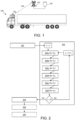
- Fig. 1 illustrates an example of a vehicle 100 where the herein disclosed embodiments may be applied with advantage.
- the vehicle 100 is exemplified as a heavy-duty vehicle combination for cargo transport.
- the vehicle 100 exemplified in Fig. 1 comprises a truck or towing vehicle configured to tow a trailer unit in a known manner, e.g., by a fifth wheel connection.
- a heavy-duty vehicle is taken to be a vehicle designed for the handling and transport of heavier objects or large quantities of cargo.
- the vehicle 100 may further comprise any number of auxiliary systems that are connected to and consumes energy in the vehicle 100.
- auxiliary systems on-board the vehicle 100 may comprise one or more of: electronic control units (ECUs), a climate control system, a thermal Energy Storage System, ESS, an air pressure system, a Power Take-off, PTO, system, and a cabin comfort system, etc.
- ECUs electronice control units
- ESS thermal Energy Storage System
- ESS air pressure system
- PTO Power Take-off
- cabin comfort system a cabin comfort system
- the embodiments disclosed herein may be applied to a wide variety of electrically powered vehicle units.
- the embodiments disclosed herein are also applicable in, for example, rigid trucks, working machines, multi-trailer electric heavy-duty vehicles comprising one or more dolly vehicle units, etc.
- the embodiments disclosed herein are also applicable for use in any electrically powered vehicle, such as, e.g. any Battery Electric Vehicles, BEVs.
- BEVs Battery Electric Vehicles
- the embodiments herein should not be considered limited to a particular type of vehicle, but should also be considered applicable in other types of vehicles.
- a processing unit 110 on the vehicle 100 may be in communication with a remote server 120 via wireless link 140 over an access point 130 that could form part of a cellular access network such as a fifth generation (5G) or sixth generation (6G) wireless access network.
- the processing unit 110 may comprise processing circuitry, as will be described in more detail below with reference to Fig. 4 .
- one of the underlying problems of providing reliable range estimations is how to handle all of the uncertainties in all of the different factors affecting the energy consumption of vehicle along a determined route. While previously known solutions may be said to address this problem by inefficient continuous re-calculations to obtain an up-to-date single value that estimates the complete energy consumption or range of the vehicle along the route, the embodiments herein provide probabilistic distribution of the energy consumption or range of the vehicle along the route depending on the arrival time. This enables the uncertainties in the different factors to be handled when optimizing the speed of the vehicle, while also enabling reliable measurements on the energy consumption and range estimations. For example, this enables the speed to be optimized towards a maximized expected net energy consumption rather than a minimized energy consumption with set reference speed values.
- Fig. 2 is an illustrated example of actions, steps or operations which may be performed by the processing unit 110 as described above with reference to Fig. 1 .
- the processing unit 110 may be located in the vehicle 100, as described in the example of Fig. 1 , but may also be located in the remote server 130 accessible via wireless communications network.
- the method may comprise the following actions, steps or operations.
- the processing unit 110 segments the route R into a plurality of sections R 1 -R 9 . This may be performed in several different ways, but it is preferable to split the route R into sections where the driving conditions are as homogenous as possible. This means, for example, that a route R may be suitably divided into different shorter sections R n , such as, e.g. the sections R 1 -R 9 shown in Fig. 3 , in which the conditions in terms of road resistance may essentially be assumed to be constant, e.g. in regards to constant road slope, constant weather conditions, constant traffic situation, etc. This may advantageously reduce the uncertainties in the calculations for each section.
- the processing unit 110 may perform Actions 202a-202f for each segmented section R n .
- the total number of route sections is denoted by N.
- the processing unit 110 obtains a set of route section characteristic values, Rscv, that will impact the energy consumption of the vehicle 100 whilst driving within the section R n .
- Rscv route section characteristic values
- the R SCV may comprise one or more of: one or more road resistance values within the section R n , one or more road weather condition values within the section R n , one or more road reference speed values within the section R n , and an expected travel time for the section R n .
- the road resistance values may comprise: a road gradient value within the section R n , a road surface condition value within the section R n , an air density value within the section R n , a wind speed value within the section R n , and a wind direction indicator value, etc. This may quantify the road resistance conditions for the section R n .
- the one or more road weather condition values may comprise: an ambient temperature value, a sun intensity value, an ambient humidity value, an air pressure value, etc. This may quantify the road weather conditions for the section R n .
- the one or more road reference speed values may, for example, comprise speed limit values for the road within the section R n or be an averaged value thereof.
- the expected travel time for the section R n may be calculated based on the other route section characteristic values in the set, R SCV , according to standard vehicle dynamics formulas known in the art.
- this set of route section characteristic values, Rscv is vehicle independent and may therefore be collected and stored in a shared server or cloud solution, such as, in a road information hub.
- the set of route section characteristic values, R SCV may be obtained by the processing unit 110 by retrieving it from a remote server 130 accessible via wireless access network.
- the processing unit 110 In addition to obtaining the route section characteristic values, Rscv, for the section R n in Action 202a, the processing unit 110 also obtains a set of vehicle energy consumption values, V ECV , that will impact the energy consumption of the vehicle 100 whilst driving within the section R n at least partly based on Rscv. This means that, for each section Rn, a number of vehicle energy consumption sensitivity factors may be assigned. These factors may be considered as the main vehicle contributors to the overall vehicle energy consumption.
- the V ECV may comprise one or more of: characteristic values of the vehicle 100 that will impact the energy consumption of the vehicle 100 whilst driving within the section R n , and energy consumption values of auxiliary systems on-board the vehicle 100.
- the characteristic values of the vehicle 100 comprises one or more of: a mass value of the vehicle 100, tire characteristic values of the vehicle 100, aerodynamic values of the vehicle 100, and characteristic values of powertrain of the vehicle 100.
- the tire characteristic values of the vehicle 100 may comprise a tire rolling resistance coefficient
- characteristic values of powertrain of the vehicle 100 may comprise an efficiency value of the powertrain and/or an energy recuperation capability value.
- Action 202c After obtaining Rscv and V ECV in Actions 202a-202b, the processing unit 110 estimates a first probability distribution, P 1 , of the energy consumption for the vehicle 100 whilst driving within the section R n based on Rscv, V ECV , and a first set of traffic information values, T 1 , within the section R n .
- the processing unit 110 may estimate a probability distribution that represent the energy consumption of the vehicle 100 for the section R n when there is no traffic in the section R n .
- T 1 and P 1 may represent ideal conditions for the vehicle 100 travelling the section R n .
- the traffic information values T 1 are vehicle-independent and may, in some cases, be stored on in a memory on-board the vehicle 100 or in the remote server 130 and be retrievable by the processing unit 110.
- the traffic information values, T 1 within the section R n may be obtained by the processing unit 110 by retrieving it from a remote server 130 accessible via wireless access network. This information may also be continuously updated during operation of the vehicle 100.
- the traffic information values, T 1 , within the section R n may comprise one or more of: one or more speed limitations set within the section R n , one or more static traffic rules applied within the section R n , one or more speed bump occurrences within the section R n , traffic intensity values within the section R n indicating a best case scenario according to previously stored traffic intensity values for the section R n , speed average values of vehicles within the section R n indicating a best case scenario according to previously stored speed average values for the section R n , and speed variance values of vehicles within the section R n indicating a best case scenario according to previously stored speed variance values for the section R n .
- the best case scenario may be represented by a combination of one or more of the lowest traffic intensity values, the highest speed average values, and the lowest speed variance values.
- the first probability distribution P 1 of the energy consumption for the vehicle 100 whilst driving within the section R n may be determined by setting an expected speed of the vehicle 100 within the section R n based on the set of route section characteristic values Rscv, e.g. the one or more road reference speed values and/or any other values in the set.
- the energy consumption of the vehicle 100 within the section R n may be estimated using a formula similar to Eq.
- W cons m v 2 S ⁇ v 2 0 2 + mg h S ⁇ h 0 + ⁇ AS 2 Dv wx + v ⁇ 2 + v wy 2 + mgC r C r ⁇ road S h ⁇ pt + W aux + W brake 1 ⁇ ⁇ brake
- an expected value of the energy consumption of the vehicle 100 within the section R n and a variance in the energy consumption of the vehicle 100 within the section R n may be determined for the section R n .
- estimating P 1 may comprise determining an expected value and a variance value for the energy consumption for the vehicle 100 by adding uncertainty values for one or more of the values in R SCV and V ECV .
- the first probability distribution P 1 of the energy consumption for the vehicle 100 whilst driving within the section R n may be fully defined by its variance and expected value.
- the processing unit 110 may estimate a second probability distribution, P 2 , of the energy consumption for the vehicle 100 whilst driving within the section R n based on R SCV , V ECV , and a second set of traffic information values, T 2 , within the section R n .
- the processing unit 110 may estimate a probability distribution that represent the energy consumption of the vehicle 100 for the section R n when the vehicle 100 adheres to heavy traffic in the section R n .
- T 2 and P 2 may represent non-ideal, or severe, conditions for the vehicle 100 travelling the section R n at a particular point in time.
- the traffic information values, T 2 , within the section R n may be collected, e.g.
- the traffic information values T 2 are vehicle-independent and may, in some cases, be stored on in a memory on-board the vehicle 100 or in the remote server 130 and be retrievable by the processing unit 110.
- the traffic information values, T 2 within the section R n may be obtained by the processing unit 110 by retrieving it from a remote server 130 accessible via wireless access network. This information may also be continuously updated during operation of the vehicle 100.
- the traffic information values, T 2 , within the section R n may comprise one or more of: traffic intensity values within the section R n indicating a worst case scenario according to previously stored traffic intensity values for the section R n , speed average values of vehicles within the section R n indicating a worst case scenario according to previously stored speed average values for the section R n , and speed variance values of vehicles within the section R n indicating a worst case scenario according to previously stored speed variance values for the section R n .
- the processing unit 110 may estimate a probability distribution that represent the energy consumption of the vehicle 100 for the section R n when the vehicle 100 follows the worst possible traffic in the section R n .
- T 2 and P 2 may represent the worst possible conditions for the vehicle 100 travelling the section R n at a particular point in time.
- the worst case scenario may be represented by a combination of one or more of the highest traffic intensity values, the lowest speed average values, and the highest speed variance values.
- the second probability distribution, P 2 , of the energy consumption for the vehicle 100 whilst driving within the section R n may be determined in the same way as the first probability distribution P 1 of the energy consumption for the vehicle 100 whilst driving within the section R n , except in that the expected speed of the vehicle 100 within the section R n is based on the average speed of the traffic within the section R n .
- formulas similar to Eq. 1 and 2 may be used to estimate P 2 in a similar manner as when estimating P 1 in Action 202c, but instead using the average speed of the traffic within the section R n .
- an expected value of the energy consumption of the vehicle 100 within the section R n and a variance in the energy consumption of the vehicle 100 within the section R n may be determined for the section R n .
- estimating P 2 may comprise determining an expected value and a variance value for the energy consumption for the vehicle 100 by adding uncertainty values for one or more of the values in R SCV and V ECV .
- the second probability distribution P 2 of the energy consumption for the vehicle 100 whilst driving within the section R n may be fully defined by its variance and expected value.
- the processing unit 110 may also estimate a traffic flow indicator, I TF , for the section R n based on R SCV , V ECV and a third set of traffic information values, T 3 , within the section R n .
- This traffic flow indicator I TF may advantageously be used to determine how the actual traffic situation within the section R n compares to the ideal conditions assumed in Action 202c and the non-ideal conditions assumed in Action 202d.
- the traffic information values, T 3 , within the section R n may comprise one or more of: an estimated traffic value for the section R n indicating the current traffic situation in the section R n ,an estimated current travel time for the section R n , and one or more additional estimated traffic values for the section R n indicating previous traffic situations in the section R n . This means that different factor may be used or averaged to compiled a traffic density value representing the actual traffic situation within the section R n .
- the traffic information values, T 3 , within the section R n may be obtained by the processing unit 110 by retrieving it from a remote server 130 accessible via wireless access network. This information may also be continuously updated during operation of the vehicle 100.
- a machine learning algorithm or model may be trained to determine the function f based on data comprising a number of vehicle speed profiles for different traffic density values.
- the I TF may here be either a deterministic value or represented as a probability distribution.
- estimating I TF may comprise determining an expected value and a variance value for the energy consumption for the vehicle 100 by adding uncertainty values for one or more of the values in R SCV and V ECV .
- the processing unit 110 may further determine a route section probability distribution, P RS , of the energy consumption for the vehicle 100 whilst driving within the section R n based on the relation between P 1 , P 2 , and I TF .
- P RS route section probability distribution
- the ITF may be used to interpolate between P1 and P2, to reflect the actual traffic situation within the section Rn.
- an expected value of the energy consumption of the vehicle 100 within the section R n and a variance in the energy consumption of the vehicle 100 within the section R n may be determined for the section R n .
- the route section probability distribution P RS of the energy consumption for the vehicle 100 whilst driving within the section R n may be fully defined by its variance and expected value.
- the processing unit 110 may determine a route probability distribution, P R , of the energy consumption for the vehicle 100 whilst driving along the route R based on the estimated P RS for all sections R n .
- P R a route probability distribution
- the estimated P RS for all sections R n may be merged into a complete route probability distribution P R of the energy consumption for the vehicle 100 whilst driving the route R.
- This has the advantage of only requiring recalculations of the current section R n in which the vehicle 110 is travelling instead of recalculating the entire route R. This may significantly reduce the computational load on the processing unit 110.
- the energy consumption for the vehicle 100 whilst driving along the route R from a source location S to a target destination T as shown in Fig. 3 may be determined based on all of the estimated energy consumptions for the vehicle 100 whilst driving within all sections R n .
- the route probability distribution, P R of the energy consumption for the vehicle 100 whilst driving along the route R may be determined based on the expected value and the variance of sum of all W sections .
- the processing unit 110 may determine one or more range estimations having a determined level of reliability for the vehicle 100 along the route R based on the estimated P R . For example, by being able to handle uncertainties, the range estimations herein will obtain a higher level of reliability than other deterministic range estimations.
- the processing unit 110 may transmit the determined one or more range estimations to the vehicle 100.
- the processing may advantageously be, at least partly, performed elsewhere according to some embodiments, and not necessarily on-board the vehicle 100.
- the processing unit 110 may comprise the following arrangement depicted in Fig. 4.
- Fig. 4 shows a schematic block diagram of embodiments of the processing unit 110. It should also be noted that, although not shown in Fig. 4 , known conventional features for operating a processing unit 110, such as, for example, a connection to a power source, e.g. a battery or the mains, may be assumed to be comprised in the processing unit 110, but is not shown or described in any further detail in regards to Fig. 4 .
- the processing unit 110 may comprise processing circuitry 410 and a memory 420. It should also be noted that some or all of the functionality described in the embodiments above as being performed by the processing unit 110 may be provided by the processing circuitry 410 executing instructions stored on a computer-readable medium, such as, e.g. the memory 420 shown in Fig. 4 . Alternative embodiments of the processing unit 110 may comprise additional components, such as, for example, an segmenting module 411, an obtaining module 412, an estimating module 413, and a determining 414, whereby each module may be configured and responsible for providing its dedicated functionality to support the embodiments described herein.
- the obtaining module 411 may form part of, or be connected to, the I/O module 430, or transceiver, for receiving and transmitting data information over a wireless network.
- the I/O module 430 may also be connected to one or more antennas 450.
- the processing unit 110 or processing circuitry 410 is configured to, or may comprise the segmenting module 411 being configured to, segment the route R into a plurality of sections R n . Also, the processing unit 110 or processing circuitry 410 is configured to, or may comprise the obtaining module 412 being configured to, for each section R n , obtain a set of route section characteristic values, Rscv, that will impact the energy consumption of the vehicle 100 whilst driving within the section R n .
- processing unit 110 or processing circuitry 410 is configured to, or may comprise the obtaining module 412 being configured to, for each section R n , obtain a set of vehicle energy consumption values, V ECV , that will impact the energy consumption of the vehicle 100 whilst driving within the section R n at least partly based on Rscv.
- the processing unit 110 or processing circuitry 410 is also configured to, or may comprise the estimating module 413 being configured to, for each section R n , estimate a first probability distribution, P 1 , of the energy consumption for the vehicle 100 whilst driving within the section R n based on R SCV , V ECV , and a first set of traffic information values, T 1 , within the section R n .
- the processing unit 110 or processing circuitry 410 is further configured to, or may comprise the estimating module 413 being configured to, for each section R n , estimate a second probability distribution, P 2 , of the energy consumption for the vehicle 100 whilst driving within the section R n based on Rscv, V ⁇ cv, and a second set of traffic information values, T 2 , within the section R n . Furthermore, the processing unit 110 or processing circuitry 410 is further configured to, or may comprise the estimating module 413 being configured to, for each section R n , estimate a traffic flow indicator, I TF , for the section R n based on R SCV , V ECV and a third set of traffic information values, T 3 , within the section R n .
- processing unit 110 or processing circuitry 410 is further configured to, or may comprise the determining module 414 being configured to, for each section R n , determine a route section probability distribution, P RS , of the energy consumption for the vehicle 100 whilst driving within the section R n based on the relation between I TF , P 1 , and P 2 .
- the processing unit 110 or processing circuitry 410 is also configured to, or may comprise the determining module 414 being configured to, determine a route probability distribution, P R , of the energy consumption for the vehicle 100 whilst driving along the route R based on the estimated P RS for all sections R n .
- the processing unit 110 or processing circuitry 410 may be configured to, or may comprise the determining module 414 being configured to, determine one or more range estimations having a determined level of reliability for the vehicle 100 along the route R based on the estimated P R . Further, the processing unit 110 or processing circuitry 410 may be configured to, or may comprise the estimating module 413 being configured to, estimate P 1 , P 2 and I TF by determining an expected value and a variance value for the energy consumption for the vehicle 100 by adding uncertainty values for one or more of R SCV and V ECV , as well as, T 1 , T 2 , and T 3 , respectively.
- R SCV may comprise one or more of: one or more road resistance values within the section R n , one or more road weather condition values within the section R n , one or more road reference speed values within the section R n , and a travel time for the section R n .
- T 1 may comprise one or more of: one or more speed limitations set within the section R n , one or more static traffic rules applied within the section R n , one or more speed bump occurrences within the section R n , traffic intensity values within the section R n indicating a best case scenario according to previously stored traffic intensity values for the section R n , speed average values of vehicles within the section R n indicating a best case scenario according to previously stored speed average values for the section R n , and speed variance values of vehicles within the section R n indicating a best case scenario according to previously stored speed variance values for the section R n .
- T 2 may comprise one or more of: traffic intensity values within the section R n indicating a worst case scenario according to previously stored traffic intensity values for the section R n , speed average values of vehicles within the section R n indicating a worst case scenario according to previously stored speed average values for the section R n , and speed variance values of vehicles within the section R n indicating a worst case scenario according to previously stored speed variance values for the section R n .
- the best case scenario may be represented by a combination of one or more of the lowest traffic intensity values, the highest speed average values, and the lowest speed variance values
- the worst case scenario may be represented by a combination of one or more of the highest traffic intensity values, the lowest speed average values, and the highest speed variance values.
- T 3 may comprise one or more of: an estimated traffic value for the section R n indicating the current traffic situation in the section R n , an estimated current travel time for the section R n , and one or more additional estimated traffic values for the section R n indicating previous traffic situations in the section R n .
- V ECV may comprise one or more of: characteristic values of the vehicle 100 that will impact the energy consumption of the vehicle 100 whilst driving within the section R n , and energy consumption values of auxiliary systems on-board the vehicle 100.
- the characteristic values of the vehicle 100 comprises one or more of: a mass value of the vehicle 100, tire characteristic values of the vehicle 100, aerodynamic values of the vehicle 100, and characteristic values of powertrain of the vehicle 100.
- the processing unit 110 may be located in a server 103 accessible via wireless network.
- the processing unit 110 or processing circuitry 410 is configured to, or may comprise the obtaining module 412 being configured to, transmit the determined one or more range estimations to the vehicle 100.
- the embodiments for enabling reliable range estimations for a vehicle 100 along a route R from a source location S to a target destination T described above may be at least partly implemented through one or more processors, such as, the processing circuitry 410 in the processing unit 110 depicted in Fig. 4 , together with computer program code for performing the functions and actions of the embodiments herein.
- the program code mentioned above may also be provided as a computer program product, for instance in the form of a data carrier carrying computer program code or code means for performing the embodiments herein when being loaded into the processing circuitry 410 in the processing unit 110.
- the data carrier, or computer readable medium may be one of an electronic signal, optical signal, radio signal or computer-readable storage medium.
- the computer program code may e.g.
- processing unit 110 may in some embodiments be implemented as computer programs stored in memory 420 in Fig. 4 , e.g. a computer readable storage unit, for execution by processors or processing modules, e.g. the processing circuitry 410 in the processing unit 110 of Fig. 4 .
- processing circuitry 410 and the memory 420 described above may refer to a combination of analog and digital circuits, and/or one or more processors configured with software and/or firmware, e.g. stored in a memory, that when executed by the one or more processors such as the processing circuitry 410 perform as described above.
- processors as well as the other digital hardware, may be included in a single application-specific integrated circuit (ASIC), or several processors and various digital hardware may be distributed among several separate components, whether individually packaged or assembled into a system-on-a-chip (SoC).
- ASIC application-specific integrated circuit
- SoC system-on-a-chip
- a computer-readable medium may include removable and non-removable storage devices including, but not limited to, Read Only Memory (ROM), Random Access Memory (RAM), compact discs (CDs), digital versatile discs (DVD), etc.
- program modules may include routines, programs, objects, components, data structures, etc. that perform particular tasks or implement particular abstract data types.
- Computer-executable instructions, associated data structures and program modules represent examples of program code for executing steps of the methods disclosed herein.
Landscapes
- Engineering & Computer Science (AREA)
- Radar, Positioning & Navigation (AREA)
- Remote Sensing (AREA)
- Power Engineering (AREA)
- Automation & Control Theory (AREA)
- Mechanical Engineering (AREA)
- Transportation (AREA)
- Physics & Mathematics (AREA)
- General Physics & Mathematics (AREA)
- Life Sciences & Earth Sciences (AREA)
- Environmental Sciences (AREA)
- Environmental & Geological Engineering (AREA)
- Computer Networks & Wireless Communication (AREA)
- Signal Processing (AREA)
- Ecology (AREA)
- Biodiversity & Conservation Biology (AREA)
- Atmospheric Sciences (AREA)
- Sustainable Development (AREA)
- Sustainable Energy (AREA)
- Traffic Control Systems (AREA)
Claims (16)
- Verfahren, das durch eine Verarbeitungseinheit (110) durchgeführt wird, zum Ermöglichen zuverlässiger Reichweitenschätzungen für ein Fahrzeug (100) entlang einer Route (R) von einem Ausgangsort (S) zu einem Zielort (T), wobei das Verfahren Folgendes umfasst:Segmentieren (301) der Route (R) in eine Vielzahl von Abschnitten (Rn);für jeden Abschnitt (Rn):Erlangen (302a) eines Satzes von Routenabschnittskennwerten, RSCV, der den Energieverbrauch des Fahrzeugs (100) während einer Fahrt innerhalb des Abschnitts (Rn) beeinflussen wird, undErlangen (302b) eines Satzes von Fahrzeugenergieverbrauchswerten, VECV, der den Energieverbrauch des Fahrzeugs (100) während der Fahrt innerhalb des Abschnitts (Rn) mindestens teilweise basierend auf dem RSCV beeinflussen wird;wobei das Verfahren ferner durch Folgendes gekennzeichnet ist:
für jeden Abschnitt (Rn):Schätzen (302c) einer ersten Wahrscheinlichkeitsverteilung, P1, des Energieverbrauchs für das Fahrzeug während der Fahrt innerhalb des Abschnitts (Rn) basierend auf RSCV, VECV und einem ersten Satz von Verkehrsinformationswerten, T1, innerhalb des Abschnitts (Rn), wobei der erste Satz von Verkehrsinformationswerten, T1, Werte umfasst, die einen bestmöglichen Fall für den Abschnitt (Rn) angeben,Schätzen (302d) einer zweiten Wahrscheinlichkeitsverteilung, P2, des Energieverbrauchs für das Fahrzeug (100) während der Fahrt innerhalb des Abschnitts (Rn) basierend auf RSCV, VECV und einem zweiten Satz von Verkehrsinformationswerten, T2, innerhalb des Abschnitts (Rn), wobei der zweite Satz von Verkehrsinformationen, T2, Werte umfasst, die einen schlimmstmöglichen Fall für den Abschnitt (Rn) angeben,Schätzen (302e) einer Verkehrsflussangabe, ITF, für den Abschnitt (Rn) basierend auf RSCV, VECV und einem dritten Satz von Verkehrsinformationswerten, T3, innerhalb des Abschnitts (Rn), wobei der dritte Satz von Verkehrsinformationswerten, T3, Werte umfasst, die eine aktuelle Verkehrssituation für den Abschnitt (Rn) angeben, undBestimmen (302f) einer Routenabschnittswahrscheinlichkeitsverteilung, PRS, des Energieverbrauchs für das Fahrzeug (100) während der Fahrt innerhalb des Abschnitts (Rn) basierend auf der Beziehung zwischen P1, P2 und ITF; und ebenfallsBestimmen (303) einer Routenwahrscheinlichkeitsverteilung, PR, des Energieverbrauchs für das Fahrzeug (100) während der Fahrt entlang der Route (R) basierend auf der geschätzten PRS für alle Abschnitte (Rn); undBestimmen (304) einer oder mehrerer Reichweitenschätzungen, die eine bestimmte Zuverlässigkeitsebene aufweisen, für das Fahrzeug (100) entlang der Route (R) basierend auf der geschätzten PR. - Verfahren nach Anspruch 1, wobei die Schätzung von P1, P2 und ITF Bestimmen eines erwarteten Wertes und eines Varianzwertes für den Energieverbrauch des Fahrzeugs (100) durch jeweiliges Hinzufügen von Unsicherheitswerten für einen oder mehrere von RSCV und VECV sowie T1, T2 und T3 umfasst.
- Verfahren nach einem der Ansprüche 1-2, wobei RSCV eines oder mehrere von Folgendem umfasst:- einem oder mehreren Straßenwiderstandswerten innerhalb des Abschnitts (Rn),- einem oder mehreren Straßenwitterungsbedingungswerten innerhalb des Abschnitts (Rn),- einem oder mehreren Straßenreferenzgeschwindigkeitswerten innerhalb des Abschnitts (Rn) und- einer Reisezeit für den Abschnitt (Rn).
- Verfahren nach einem der Ansprüche 1-3, wobei T1 eines oder mehrere von Folgendem umfasst:- einer oder mehreren Geschwindigkeitsbeschränkungen, die innerhalb des Abschnitts (Rn) festgelegt sind,- einer oder mehreren statischen Verkehrsregeln, die innerhalb des Abschnitts (Rn) angewandt werden,- einem oder mehreren Vorkommen von Rüttelschwellen innerhalb des Abschnitts (Rn),- Verkehrsintensitätswerten innerhalb des Abschnitts (Rn), die einen bestmöglichen Fall gemäß zuvor gespeicherten Verkehrsintensitätswerten für den Abschnitt (Rn) angeben,- Geschwindigkeitsdurchschnittswerten von Fahrzeugen innerhalb des Abschnitts (Rn), die einen bestmöglichen Fall gemäß zuvor gespeicherten Geschwindigkeitsdurchschnittswerten für den Abschnitt (Rn) angeben, und- Geschwindigkeitsvarianzwerten von Fahrzeugen innerhalb des Abschnitts (Rn), die einen bestmöglichen Fall gemäß zuvor gespeicherten Geschwindigkeitsvarianzwerten für den Abschnitt (Rn) angeben.
- Verfahren nach einem der Ansprüche 1-4, wobei T2 eines oder mehrere von Folgendem umfasst:- Verkehrsintensitätswerten innerhalb des Abschnitts (Rn), die einen schlimmstmöglichen Fall gemäß zuvor gespeicherten Verkehrsintensitätswerten für den Abschnitt (Rn) angeben,- Geschwindigkeitsdurchschnittswerten von Fahrzeugen innerhalb des Abschnitts (Rn), die einen schlimmstmöglichen Fall gemäß zuvor gespeicherten Geschwindigkeitsdurchschnittswerten für den Abschnitt (Rn) angeben, und- Geschwindigkeitsvarianzwerten von Fahrzeugen innerhalb des Abschnitts (Rn), die einen schlimmstmöglichen Fall gemäß zuvor gespeicherten Geschwindigkeitsvarianzwerten für den Abschnitt (Rn) angeben.
- Verfahren nach einem der Ansprüche 4-5, wobei der bestmögliche Fall durch eine Kombination eines oder mehrerer der niedrigsten Verkehrsintensitätswerte, der höchsten Geschwindigkeitsdurchschnittswerte und der niedrigsten Geschwindigkeitsvarianzwerte dargestellt wird und der schlimmstmögliche Fall durch eine Kombination eines oder mehrerer der höchsten Verkehrsintensitätswerte, der niedrigsten Geschwindigkeitsdurchschnittswerte und der höchsten Geschwindigkeitsvarianzwerte dargestellt wird.
- Verfahren nach einem der Ansprüche 1-6, wobei T3 eines oder mehrere von Folgendem umfasst:- einem geschätzten Verkehrswert für den Abschnitt (Rn), der die aktuelle Verkehrssituation in dem Abschnitt (Rn) angibt,- einer geschätzten aktuellen Reisezeit für den Abschnitt (Rn) und- einem oder mehreren zusätzlichen geschätzten Verkehrswerten für den Abschnitt (Rn), die vorherige Verkehrssituationen in dem Abschnitt (Rn) angeben.
- Verfahren nach einem der Ansprüche 1-7, wobei einer oder mehrere von RSCV, T1, T2 und T3 von einem entfernten Server (130) erlangt werden, der über ein drahtloses Kommunikationsnetz (102) zugänglich ist.
- Verfahren nach einem der Ansprüche 1-8, wobei VECV eines oder mehrere von Folgendem umfasst:- Kennwerten des Fahrzeugs (100), die den Energieverbrauch des Fahrzeugs (100) während der Fahrt innerhalb des Abschnitts (Rn) beeinflussen werden, und- Energieverbrauchswerten von Hilfssystemen an Bord des Fahrzeugs (100).
- Verfahren nach Anspruch 9, wobei die Kennwerte des Fahrzeugs (100) einen oder mehrere von Folgendem umfassen:- einem Massenwert des Fahrzeugs (100),- Reifenkennwerten des Fahrzeugs (100),- aerodynamischen Werten des Fahrzeugs (100) und- Kennwerten einer Antriebskraft des Fahrzeugs (100).
- Verfahren nach einem der Ansprüche 1-10, wobei sich die Verarbeitungseinheit (110) in einem entfernten Server (130) befindet, der über ein drahtloses Netz zugänglich ist.
- Verfahren nach Anspruch 11, ferner umfassend Übertragen (206) der bestimmten einen oder mehreren Reichweitenschätzungen an das Fahrzeug (100).
- Verarbeitungseinheit (110) zum Ermöglichen zuverlässiger Reichweitenschätzungen für ein Fahrzeug (100) entlang einer Route (R) von einem Ausgangsort (S) zu einem Zielort (T), wobei die Verarbeitungseinheit (110) zu Folgendem konfiguriert ist:Segmentieren der Route (R) in eine Vielzahl von Abschnitten (Rn) undfür jeden Abschnitt (Rn) Erlangen eines Satzes von Routenabschnittskennwerten, RSCV, der den Energieverbrauch des Fahrzeugs (100) während einer Fahrt innerhalb des Abschnitts (Rn) beeinflussen wird, und Erlangen eines Satzes von Fahrzeugenergieverbrauchswerten, VECV, der den Energieverbrauch des Fahrzeugs (100) während der Fahrt innerhalb des Abschnitts (Rn) mindestens teilweise basierend auf dem RSCV beeinflussen wird,wobei die Verarbeitungseinheit (110) ferner durch Folgendes gekennzeichnet ist: für jeden Abschnitt (Rn) Schätzen einer ersten Wahrscheinlichkeitsverteilung, P1, des Energieverbrauchs für das Fahrzeug (100) während der Fahrt innerhalb des Abschnitts (Rn) basierend auf RSCV, VECV und einem ersten Satz von Verkehrsinformationswerten, T1, innerhalb des Abschnitts (Rn), wobei der erste Satz von Verkehrsinformationswerten, T1, Werte umfasst, die einen bestmöglichen Fall für den Abschnitt (Rn) angeben, Schätzen einer zweiten Wahrscheinlichkeitsverteilung, P2, des Energieverbrauchs für das Fahrzeug (100) während der Fahrt innerhalb des Abschnitts (Rn) basierend auf RSCV, VECV und einem zweiten Satz von Verkehrsinformationswerten, T2, innerhalb des Abschnitts (Rn), wobei der zweite Satz von Verkehrsinformationen, T2, Werte umfasst, die einen schlimmstmöglichen Fall für den Abschnitt (Rn) angeben, Schätzen einer Verkehrsflussangabe, ITF, für den Abschnitt (Rn) basierend auf RSCV, VECV und einem dritten Satz von Verkehrsinformationswerten, T3, innerhalb des Abschnitts (Rn), wobei der dritte Satz von Verkehrsinformationswerten, T3, Werte umfasst, die eine aktuelle Verkehrssituation für den Abschnitt (Rn) angeben, und Bestimmen einer Routenabschnittswahrscheinlichkeitsverteilung, PRS, des Energieverbrauchs für das Fahrzeug (100) während der Fahrt innerhalb des Abschnitts (Rn) basierend auf der Beziehung zwischen ITF, P1 und P2; und ebenfallsBestimmen einer Routenwahrscheinlichkeitsverteilung, PR, des Energieverbrauchs für das Fahrzeug (100) während der Fahrt entlang der Route (R) basierend auf der geschätzten PRS für alle Abschnitte (Rn) und Bestimmen einer oder mehrerer Reichweitenschätzungen, die eine bestimmte Zuverlässigkeitsebene aufweisen, für das Fahrzeug (100) entlang der Route (R) basierend auf der geschätzten PR.
- Computerprogramm, umfassend Programmcodemittel zum Durchführen der Schritte nach einem der Ansprüche 1-12, wenn das Programm auf einem Computer oder in einem Verarbeitungsschaltkreis (410) ausgeführt wird.
- Computerprogrammträger, der ein Computerprogramm nach Anspruch 14 trägt, wobei der Computerprogrammträger eines von einem elektronischen Signal, einem optischen Signal, einem Funksignal oder einem computerlesbaren Speichermedium ist.
- Fahrzeug (31a), umfassend eine Verarbeitungseinheit (110) nach Anspruch 13.
Priority Applications (2)
| Application Number | Priority Date | Filing Date | Title |
|---|---|---|---|
| EP22152425.9A EP4215875B1 (de) | 2022-01-20 | 2022-01-20 | Verarbeitungseinheit und verfahren zum ermöglichen einer zuverlässigen reichweitenschätzung für ein fahrzeug entlang einer route |
| US18/156,169 US12359930B2 (en) | 2022-01-20 | 2023-01-18 | Processing unit and method therein for enabling reliable range estimations for a vehicle along a route |
Applications Claiming Priority (1)
| Application Number | Priority Date | Filing Date | Title |
|---|---|---|---|
| EP22152425.9A EP4215875B1 (de) | 2022-01-20 | 2022-01-20 | Verarbeitungseinheit und verfahren zum ermöglichen einer zuverlässigen reichweitenschätzung für ein fahrzeug entlang einer route |
Publications (3)
| Publication Number | Publication Date |
|---|---|
| EP4215875A1 EP4215875A1 (de) | 2023-07-26 |
| EP4215875C0 EP4215875C0 (de) | 2024-12-25 |
| EP4215875B1 true EP4215875B1 (de) | 2024-12-25 |
Family
ID=79831151
Family Applications (1)
| Application Number | Title | Priority Date | Filing Date |
|---|---|---|---|
| EP22152425.9A Active EP4215875B1 (de) | 2022-01-20 | 2022-01-20 | Verarbeitungseinheit und verfahren zum ermöglichen einer zuverlässigen reichweitenschätzung für ein fahrzeug entlang einer route |
Country Status (2)
| Country | Link |
|---|---|
| US (1) | US12359930B2 (de) |
| EP (1) | EP4215875B1 (de) |
Families Citing this family (5)
| Publication number | Priority date | Publication date | Assignee | Title |
|---|---|---|---|---|
| DE102020121696A1 (de) * | 2020-08-19 | 2022-02-24 | Bayerische Motoren Werke Aktiengesellschaft | Steuervorrichtung und Verfahren zum prädiktiven Betreiben eines Energiebordnetzes |
| EP4425102A1 (de) * | 2023-03-01 | 2024-09-04 | Volvo Truck Corporation | Reichweitenvorhersage für elektrofahrzeuge |
| WO2025073375A1 (en) | 2023-10-06 | 2025-04-10 | Volvo Truck Corporation | Sensor arrangement for determining operating conditions of a vehicle |
| KR20260006916A (ko) * | 2024-07-05 | 2026-01-13 | 현대자동차주식회사 | 차량 제어 장치 및 그 방법 |
| EP4678495A1 (de) | 2024-07-08 | 2026-01-14 | Volvo Truck Corporation | Ansätze zur bestimmung von betriebsbedingungen eines fahrzeugs |
Family Cites Families (16)
| Publication number | Priority date | Publication date | Assignee | Title |
|---|---|---|---|---|
| US8972161B1 (en) | 2005-11-17 | 2015-03-03 | Invent.Ly, Llc | Power management systems and devices |
| DE102007045991A1 (de) * | 2007-09-26 | 2009-04-02 | Siemens Ag | Verfahren zur Ermittlung von Verbrauchs- und/oder Emissionswerten |
| EP2354762B1 (de) * | 2010-02-05 | 2013-11-27 | Harman Becker Automotive Systems GmbH | Navigationssystem und Verfahren zur Bestimmung der Parameter in einem Navigationssystem |
| US8755993B2 (en) * | 2011-03-08 | 2014-06-17 | Navteq B.V. | Energy consumption profiling |
| US8554473B2 (en) * | 2011-04-25 | 2013-10-08 | Navteq B.V. | Energy efficient routing using an impedance factor |
| US10048082B2 (en) * | 2014-08-29 | 2018-08-14 | Ford Global Technologies, Llc | Route and model based energy estimation |
| US9759573B2 (en) | 2014-08-29 | 2017-09-12 | Ford Global Technologies, Llc | Route based energy consumption estimation using physical models |
| US9612130B2 (en) * | 2014-10-01 | 2017-04-04 | Ford Global Technologies, Llc | System and method of estimating available driving distance |
| EP3106836B1 (de) * | 2015-06-16 | 2018-06-06 | Volvo Car Corporation | Einheit und verfahren zur einstellung einer strassenbegrenzung |
| JP6551332B2 (ja) * | 2016-07-26 | 2019-07-31 | トヨタ自動車株式会社 | 車両の走行可能距離算出システムおよび走行可能距離算出方法 |
| WO2018035087A1 (en) * | 2016-08-15 | 2018-02-22 | Massachusetts Institute Of Technology | System and method for estimating and predicting vehicle trip energy consumption |
| WO2018087550A2 (en) * | 2016-11-09 | 2018-05-17 | Inventive Cogs (Campbell) Limited | Vehicle route guidance |
| CN113015885A (zh) * | 2018-11-13 | 2021-06-22 | 麦格纳国际公司 | 使用大数据进行车辆路由的系统和方法 |
| DE102019129807A1 (de) * | 2019-11-05 | 2021-05-06 | Bayerische Motoren Werke Aktiengesellschaft | Verfahren für eine Energiebedarfsprognose eines Fahrzeugs und System für eine Energiebedarfsprognose eines Fahrzeugs |
| CN111483322B (zh) | 2020-04-27 | 2021-10-15 | 中国第一汽车股份有限公司 | 一种车辆剩余里程确定方法、装置及车辆 |
| CN112406630B (zh) * | 2020-11-30 | 2024-03-19 | 的卢技术有限公司 | 一种基于工况识别的电动车续驶里程计算方法 |
-
2022
- 2022-01-20 EP EP22152425.9A patent/EP4215875B1/de active Active
-
2023
- 2023-01-18 US US18/156,169 patent/US12359930B2/en active Active
Also Published As
| Publication number | Publication date |
|---|---|
| EP4215875C0 (de) | 2024-12-25 |
| US12359930B2 (en) | 2025-07-15 |
| EP4215875A1 (de) | 2023-07-26 |
| US20230228581A1 (en) | 2023-07-20 |
Similar Documents
| Publication | Publication Date | Title |
|---|---|---|
| EP4215875B1 (de) | Verarbeitungseinheit und verfahren zum ermöglichen einer zuverlässigen reichweitenschätzung für ein fahrzeug entlang einer route | |
| Yavasoglu et al. | Implementation of machine learning based real time range estimation method without destination knowledge for BEVs | |
| CN111137107B (zh) | 车辆中使用的运输气候控制系统及其操作方法 | |
| CN107791854B (zh) | 用于估算电动车辆的可用行驶距离的系统和方法 | |
| US20230219569A1 (en) | Personalized vehicle operation for autonomous driving with inverse reinforcement learning | |
| Tannahill et al. | Driver alerting system using range estimation of electric vehicles in real time under dynamically varying environmental conditions | |
| CN114347793B (zh) | 汽车续航的估算方法及系统 | |
| US11983969B2 (en) | Systems and methods for modeling electric vehicle towing | |
| CN105480095A (zh) | 估计可用行驶距离的系统和方法 | |
| JP6898714B2 (ja) | 電気トラックの走行ルート選定システム、電気トラックの走行ルート選定方法 | |
| EP3323669B1 (de) | Fahrzeugsteuergerät (vcu) und betriebsverfahren dafür | |
| CN109383505A (zh) | 峰值效率推荐和分享 | |
| US20220357162A1 (en) | Battery management device, learning model, computer program, battery management method, and information providing device | |
| JP2024529003A (ja) | 規定のルートに沿った車両の移動に関する車両のエネルギー消費量を予測するための、およびルート設定のための方法およびシステム | |
| US20240391451A1 (en) | Predictive power split with zero-emission zone handling | |
| US20200094809A1 (en) | Systems and Methods for Determining Engine Start Time During Predicted Acceleration Events | |
| US11454971B2 (en) | Methods and systems for learning user preferences for lane changes | |
| US12559107B2 (en) | Range prediction for vehicles | |
| CN120245722A (zh) | 用于优化电气化运输制冷单元(e-tru)的功率供应的功率系统和方法 | |
| US12296834B2 (en) | Energy estimation apparatus | |
| Ishizuki et al. | Image and CAIS features-based estimation of road surface condition on winter local road | |
| US20220274490A1 (en) | Device and Method to Determine Available Regenerative Braking Energy in a Route for Vehicle | |
| US12559023B2 (en) | Situational external display | |
| US20250123112A1 (en) | Method for controlling a vehicle, a control system for a vehicle | |
| Schmid et al. | Prediction model for energy consumption in heavy-duty vehicle formations |
Legal Events
| Date | Code | Title | Description |
|---|---|---|---|
| PUAI | Public reference made under article 153(3) epc to a published international application that has entered the european phase |
Free format text: ORIGINAL CODE: 0009012 |
|
| STAA | Information on the status of an ep patent application or granted ep patent |
Free format text: STATUS: THE APPLICATION HAS BEEN PUBLISHED |
|
| AK | Designated contracting states |
Kind code of ref document: A1 Designated state(s): AL AT BE BG CH CY CZ DE DK EE ES FI FR GB GR HR HU IE IS IT LI LT LU LV MC MK MT NL NO PL PT RO RS SE SI SK SM TR |
|
| STAA | Information on the status of an ep patent application or granted ep patent |
Free format text: STATUS: REQUEST FOR EXAMINATION WAS MADE |
|
| 17P | Request for examination filed |
Effective date: 20240125 |
|
| RBV | Designated contracting states (corrected) |
Designated state(s): AL AT BE BG CH CY CZ DE DK EE ES FI FR GB GR HR HU IE IS IT LI LT LU LV MC MK MT NL NO PL PT RO RS SE SI SK SM TR |
|
| GRAP | Despatch of communication of intention to grant a patent |
Free format text: ORIGINAL CODE: EPIDOSNIGR1 |
|
| STAA | Information on the status of an ep patent application or granted ep patent |
Free format text: STATUS: GRANT OF PATENT IS INTENDED |
|
| RIC1 | Information provided on ipc code assigned before grant |
Ipc: B60L 53/66 20190101ALI20240621BHEP Ipc: B60L 53/30 20190101ALI20240621BHEP Ipc: B60L 1/00 20060101ALI20240621BHEP Ipc: B60L 58/12 20190101ALI20240621BHEP Ipc: G01C 21/34 20060101AFI20240621BHEP |
|
| INTG | Intention to grant announced |
Effective date: 20240730 |
|
| GRAS | Grant fee paid |
Free format text: ORIGINAL CODE: EPIDOSNIGR3 |
|
| GRAA | (expected) grant |
Free format text: ORIGINAL CODE: 0009210 |
|
| STAA | Information on the status of an ep patent application or granted ep patent |
Free format text: STATUS: THE PATENT HAS BEEN GRANTED |
|
| AK | Designated contracting states |
Kind code of ref document: B1 Designated state(s): AL AT BE BG CH CY CZ DE DK EE ES FI FR GB GR HR HU IE IS IT LI LT LU LV MC MK MT NL NO PL PT RO RS SE SI SK SM TR |
|
| REG | Reference to a national code |
Ref country code: GB Ref legal event code: FG4D |
|
| REG | Reference to a national code |
Ref country code: CH Ref legal event code: EP |
|
| REG | Reference to a national code |
Ref country code: DE Ref legal event code: R096 Ref document number: 602022008938 Country of ref document: DE |
|
| REG | Reference to a national code |
Ref country code: IE Ref legal event code: FG4D |
|
| U01 | Request for unitary effect filed |
Effective date: 20250123 |
|
| U07 | Unitary effect registered |
Designated state(s): AT BE BG DE DK EE FI FR IT LT LU LV MT NL PT RO SE SI Effective date: 20250129 |
|
| U20 | Renewal fee for the european patent with unitary effect paid |
Year of fee payment: 4 Effective date: 20250127 |
|
| PG25 | Lapsed in a contracting state [announced via postgrant information from national office to epo] |
Ref country code: HR Free format text: LAPSE BECAUSE OF FAILURE TO SUBMIT A TRANSLATION OF THE DESCRIPTION OR TO PAY THE FEE WITHIN THE PRESCRIBED TIME-LIMIT Effective date: 20241225 |
|
| PG25 | Lapsed in a contracting state [announced via postgrant information from national office to epo] |
Ref country code: NO Free format text: LAPSE BECAUSE OF FAILURE TO SUBMIT A TRANSLATION OF THE DESCRIPTION OR TO PAY THE FEE WITHIN THE PRESCRIBED TIME-LIMIT Effective date: 20250325 |
|
| PG25 | Lapsed in a contracting state [announced via postgrant information from national office to epo] |
Ref country code: GR Free format text: LAPSE BECAUSE OF FAILURE TO SUBMIT A TRANSLATION OF THE DESCRIPTION OR TO PAY THE FEE WITHIN THE PRESCRIBED TIME-LIMIT Effective date: 20250326 |
|
| PG25 | Lapsed in a contracting state [announced via postgrant information from national office to epo] |
Ref country code: RS Free format text: LAPSE BECAUSE OF FAILURE TO SUBMIT A TRANSLATION OF THE DESCRIPTION OR TO PAY THE FEE WITHIN THE PRESCRIBED TIME-LIMIT Effective date: 20250325 |
|
| PG25 | Lapsed in a contracting state [announced via postgrant information from national office to epo] |
Ref country code: SM Free format text: LAPSE BECAUSE OF FAILURE TO SUBMIT A TRANSLATION OF THE DESCRIPTION OR TO PAY THE FEE WITHIN THE PRESCRIBED TIME-LIMIT Effective date: 20241225 |
|
| PG25 | Lapsed in a contracting state [announced via postgrant information from national office to epo] |
Ref country code: PL Free format text: LAPSE BECAUSE OF FAILURE TO SUBMIT A TRANSLATION OF THE DESCRIPTION OR TO PAY THE FEE WITHIN THE PRESCRIBED TIME-LIMIT Effective date: 20241225 |
|
| PG25 | Lapsed in a contracting state [announced via postgrant information from national office to epo] |
Ref country code: ES Free format text: LAPSE BECAUSE OF FAILURE TO SUBMIT A TRANSLATION OF THE DESCRIPTION OR TO PAY THE FEE WITHIN THE PRESCRIBED TIME-LIMIT Effective date: 20241225 |
|
| PG25 | Lapsed in a contracting state [announced via postgrant information from national office to epo] |
Ref country code: IS Free format text: LAPSE BECAUSE OF FAILURE TO SUBMIT A TRANSLATION OF THE DESCRIPTION OR TO PAY THE FEE WITHIN THE PRESCRIBED TIME-LIMIT Effective date: 20250425 |
|
| PG25 | Lapsed in a contracting state [announced via postgrant information from national office to epo] |
Ref country code: SK Free format text: LAPSE BECAUSE OF FAILURE TO SUBMIT A TRANSLATION OF THE DESCRIPTION OR TO PAY THE FEE WITHIN THE PRESCRIBED TIME-LIMIT Effective date: 20241225 |
|
| PG25 | Lapsed in a contracting state [announced via postgrant information from national office to epo] |
Ref country code: CZ Free format text: LAPSE BECAUSE OF FAILURE TO SUBMIT A TRANSLATION OF THE DESCRIPTION OR TO PAY THE FEE WITHIN THE PRESCRIBED TIME-LIMIT Effective date: 20241225 |
|
| REG | Reference to a national code |
Ref country code: CH Ref legal event code: PL |
|
| PG25 | Lapsed in a contracting state [announced via postgrant information from national office to epo] |
Ref country code: MC Free format text: LAPSE BECAUSE OF FAILURE TO SUBMIT A TRANSLATION OF THE DESCRIPTION OR TO PAY THE FEE WITHIN THE PRESCRIBED TIME-LIMIT Effective date: 20241225 |
|
| PG25 | Lapsed in a contracting state [announced via postgrant information from national office to epo] |
Ref country code: CH Free format text: LAPSE BECAUSE OF NON-PAYMENT OF DUE FEES Effective date: 20250131 |
|
| PLBE | No opposition filed within time limit |
Free format text: ORIGINAL CODE: 0009261 |
|
| STAA | Information on the status of an ep patent application or granted ep patent |
Free format text: STATUS: NO OPPOSITION FILED WITHIN TIME LIMIT |
|
| 26N | No opposition filed |
Effective date: 20250926 |
|
| PG25 | Lapsed in a contracting state [announced via postgrant information from national office to epo] |
Ref country code: IE Free format text: LAPSE BECAUSE OF NON-PAYMENT OF DUE FEES Effective date: 20250120 |
|
| U20 | Renewal fee for the european patent with unitary effect paid |
Year of fee payment: 5 Effective date: 20260126 |