EP3323676A1 - Festzurr-anordnung für gegenstände auf einer oberfläche, insbesondere einem ladeboden eines transportfahrzeugs für fracht - Google Patents
Festzurr-anordnung für gegenstände auf einer oberfläche, insbesondere einem ladeboden eines transportfahrzeugs für fracht Download PDFInfo
- Publication number
- EP3323676A1 EP3323676A1 EP17199391.8A EP17199391A EP3323676A1 EP 3323676 A1 EP3323676 A1 EP 3323676A1 EP 17199391 A EP17199391 A EP 17199391A EP 3323676 A1 EP3323676 A1 EP 3323676A1
- Authority
- EP
- European Patent Office
- Prior art keywords
- ring
- base
- housing
- lashing
- support
- Prior art date
- Legal status (The legal status is an assumption and is not a legal conclusion. Google has not performed a legal analysis and makes no representation as to the accuracy of the status listed.)
- Granted
Links
Images


Classifications
-
- B—PERFORMING OPERATIONS; TRANSPORTING
- B60—VEHICLES IN GENERAL
- B60P—VEHICLES ADAPTED FOR LOAD TRANSPORTATION OR TO TRANSPORT, TO CARRY, OR TO COMPRISE SPECIAL LOADS OR OBJECTS
- B60P7/00—Securing or covering of load on vehicles
- B60P7/06—Securing of load
- B60P7/08—Securing to the vehicle floor or sides
- B60P7/0807—Attachment points
Definitions
- the invention relates to an arrangement for securing objects on a surface, in particular a loading floor of a cargo transport vehicle, of the type comprising a securing ring and hooking of a securing means.
- a securing means such as a strap or a chain
- the ring comprising a rectilinear cylindrical base engaged in a housing of complementary shape of the support , allowing pivoting of the ring in said stowed position by rotation of the base in the housing.
- the lashing arrangements which are known have the major disadvantage of not allowing to maintain the lashing ring in a position allowing the establishment of securing means such as hooks, chains or lashing straps. Generally, the operator must hold the ring with one hand to set up the securing means on it.
- the invention aims to overcome these disadvantages.
- the lashing arrangement according to the invention is characterized in that the cylindrical base of the lashing ring has a flattened central portion 19 and in that the lashing ring support is in the form of a yoke to be fixed on the supporting structure which comprises in its end adjacent to the loading floor surface a housing for the base (17) allowing the rotation thereof in this housing and below the housing, a space (26) of displacement of the base allowing the displacement of the ring in a retracted position of storage, and in that the housing is separated from the movement space 26 by a narrowed zone of passage from the base to the space, whose width is slightly greater than the thickness of the base at the level of the portion to flat, perpendicular to the flat, to allow the passage of the housing base to the displacement space only when the base is in a position in which the flat is oriented perpendicular to the passage.
- the lashing arrangement is characterized in that the support of the lashing ring comprises in the outer face of its upper end a housing groove of the fastening vertex of the ring. and at its lower end, a bearing surface on which the base bears without play when the ring is in its retracted position.
- the lashing arrangement is characterized in that the lashing ring extends, in its stowed position, beyond the loading floor surface, through a cut-out in the supporting structure, at a predetermined angle with respect to the floor surface and in that the ring is held in this position by a support means.
- the lashing arrangement is characterized in that the support of the lashing ring is capable of being fixed on a fastening surface by screws or by welding.
- the lashing arrangement is characterized in that the support of the lashing ring consists of a clevis in the form of a band whose ends each end with a leg fastening, to a surface of the supporting structure, which is perpendicular to the floor surface, the upper end portion adjacent to the floor surface being bent towards said fixing surface by forming at the top the semi-cylindrical housing of the cylindrical base of the ring, while the clevis strip forms, below the housing, the displacement space of the base which is separated from the housing by the passage narrowed by the flat portion.
- the lashing arrangement is characterized in that the support of the lashing ring in the form of a yoke comprises a median part inclined with respect to the fastening surface, which is ends at the bottom by the lower bracket and which is extended at the top by a vertical part whose end position is bent at an angle of 180 degrees and carries at its end the upper fastening tab which extends perpendicularly to this end and to the fastening surface and has on its outer surface the receiving groove of the top of the lashing ring.
- the lashing arrangements of which one is illustrated in 1 in the figures are intended to secure objects 3 on a loading surface 5, including a loading floor of a cargo transport vehicle.
- the lashing arrangement 1 is mounted in a supporting structure 7 which, on the Figures 1 and 2 is a frame that could extend along a side edge of the loading floor, that is to say the edge of the vehicle.
- the supporting structure could also be of any other suitable nature, such as an IPN spar, as shown in FIG. figure 14 .
- the lashing arrangement comprises a lashing ring 9 and a ring holder 10 which is mounted in the frame.
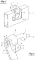
- the figure 1 shows the stowage arrangement in its working position, that is to say stowage of an object 3 on the surface of the floor 5 with a strap 14 by means of a hook 15 .
- the figure 2 shows the arrangement 1 in its retracted position in the frame 7 flush with the loading floor surface 5.
- the lashing ring comprises a rounded stirrup portion 16 for fastening the securing means and a rectilinear base 17 which connects the two ends of the stirrup.
- the base is of cylindrical shape and comprises in its central zone a flat portion 19.
- the support of this ring as seen in particular on the figure 3 , consists of a yoke in the form of a band whose ends are configured as fastening lugs 21, 22 on a surface 24 of the supporting structure, which extends perpendicularly to the loading floor, one 21 above the other 22 at a predetermined distance.
- the upper part of the screed strip which is adjacent to the loading floor, is bent in the example shown at a 180 degree angle by forming a semi-cylindrical housing 25 in which the cylindrical base of the ring can engage to allow pivoting of the ring in its stowed position as shown in FIG. figure 1 .
- the clevis defines with its attachment surface, below the housing 25, a space 26 for moving the ring from its stowed out position to its retracted retracted position, that is to say removed in the support and chassis, in accordance with figure 2 .
- the yoke comprises an inclined portion 28 which ends at the bottom by the fastening lug 22 and which extends at the top by a vertical portion 29 whose end portion is bent first at 90 degrees and then again at 90 degrees to form a descending vertical portion 31 which terminates in the bracket 21.
- This tab extends perpendicular to the vertical portion 31.
- the semi-cylindrical housing 25 is formed by the inner surfaces of the curved portions 30 and 31.
- the terms "tape-shaped screed" does not necessarily mean that the screed is made by folding a strip but it is a part with a succession of the indicated parts. This piece can be made in any suitable manner for example by molding, and any suitable material.
- the vertical clevis portion 29 is provided with a boss 34 which projects in the direction of the curved portion facing 31.
- the upper surface of the boss is in the form of a circular arc having the same radius of curvature as the housing 25 by continuing the curvature thereof.
- This boss is located, relative to the width of the yoke, in the central portion of the clevis portion 29 at the flat in the cylindrical base of the ring.
- the boss thus narrows the passage 35 between the cylindrical housing 25 and the space 26 below this housing, so that this passage is only slightly greater than the thickness of the base of the ring at the flat part. that is, the thickness of the base perpendicular to the latter.
- the base can come out of the housing only when it is in an angular position in which the flat is just above the passage, as will be explained later.
- the outer surface of the upper fastening lug 21 is in the form of a groove which is bent in a plane parallel to the fastening surface of the chassis, on the one hand and whose bottom is also curved, of complementary manner to the diameter of the bow of the stirrup and the diameter of the stirrup, so that the stirrup can be housed in this groove in its retracted position.
- the base of the ring is supported on a bearing surface 37 of the lower fastening tab 22.
- the inclined clevis portion 28 has at the bottom, above its leg 22 an outer boss 39 on which can bear the upper part of the stirrup in the retracted position of the figure 12 .
- the stirrup it is found that it has, on either side of the median line perpendicular to the base, at the top of the stirrup, excrescences 42 which facilitate the seizure of the ring of stowage.
- FIG. 13A shows the lashing ring 9 in its stowed position, in which the base is engaged in the housing 25. In this position, the ring extends outwards through a cutout 50 in the frame 7 and is supported at 51 on the edge of this cut by being inclined at an angle of for example 30 degrees. Since the ring is in support, the operator who must hang the securing means at the top of the ring, no longer needs to hold it.
- the Figure 13B shows the ring in another extended position in which it bears on the horizontal outer edge 32 of the cutout 50.
- the displacement of the ring between these two positions is done by pivoting the ring and rotating the base in 25. It is only by raising the ring vertically, in the position shown in figure 7 where the flat 19 is substantially perpendicular to the housing exit surface, i.e., the passageway, and exerting a slight rotation, the flattened portion of the ring can be passed through the narrowing produced by the boss and through it in space 26 underneath, as shown in the figure 8 . After the passage of the ring base in the wider space from below, the ring can be rotated into its position illustrated in FIG.
- the figure 14 shows the mounting of the lashing support bracket on an IPN spar. As illustrated in the figures, the support is fixed either by screw or by welding on the strip of the profile.
- the support of the lashing ring may have any other suitable form, provided that the housing of the base of the ring, of cylindrical shape on at least the greater part of its periphery, and a portion in the form of a flat part, and the passage of width narrowed but slightly greater than the thickness of the base, perpendicularly to the flat part , so as to allow the passage of the base of its housing to the movement space below, only according to the angular position of the base relative to the passage.
- the receiving groove of the rounded part of the stirrup of the ring and the bearing surface of the base configured to ensure a retracted position of the ring without play can be realized in a manner different appropriate.
Landscapes
- Engineering & Computer Science (AREA)
- Transportation (AREA)
- Mechanical Engineering (AREA)
- Fittings On The Vehicle Exterior For Carrying Loads, And Devices For Holding Or Mounting Articles (AREA)
- Clamps And Clips (AREA)
Priority Applications (1)
| Application Number | Priority Date | Filing Date | Title |
|---|---|---|---|
| PL17199391T PL3323676T3 (pl) | 2016-11-16 | 2017-10-31 | Układ zabezpieczający przedmioty na powierzchni, zwłaszcza podłogi ładunkowej pojazdu do przewozu ładunku |
Applications Claiming Priority (1)
| Application Number | Priority Date | Filing Date | Title |
|---|---|---|---|
| FR1661106A FR3058688B1 (fr) | 2016-11-16 | 2016-11-16 | Agencement d'arrimage d'objets sur une surface, notamment d'un plancher de chargement d'un vehicule de transport de cargaisons |
Publications (2)
| Publication Number | Publication Date |
|---|---|
| EP3323676A1 true EP3323676A1 (de) | 2018-05-23 |
| EP3323676B1 EP3323676B1 (de) | 2020-02-26 |
Family
ID=57909669
Family Applications (1)
| Application Number | Title | Priority Date | Filing Date |
|---|---|---|---|
| EP17199391.8A Active EP3323676B1 (de) | 2016-11-16 | 2017-10-31 | Festzurr-anordnung für gegenstände auf einer oberfläche, insbesondere einem ladeboden eines transportfahrzeugs für fracht |
Country Status (4)
| Country | Link |
|---|---|
| EP (1) | EP3323676B1 (de) |
| ES (1) | ES2793403T3 (de) |
| FR (1) | FR3058688B1 (de) |
| PL (1) | PL3323676T3 (de) |
Cited By (2)
| Publication number | Priority date | Publication date | Assignee | Title |
|---|---|---|---|---|
| CN111609794A (zh) * | 2020-04-24 | 2020-09-01 | 北京控制工程研究所 | 一种基于双机械臂抓捕的目标卫星星箭对接环抓捕点定位方法 |
| EP4357196A3 (de) * | 2022-09-15 | 2024-07-10 | Thiele GmbH & Co. KG | Schwenkbarer zurrpunkt für die ladefläche eines transportfahrzeuges |
Citations (3)
| Publication number | Priority date | Publication date | Assignee | Title |
|---|---|---|---|---|
| FR2782040A1 (fr) * | 1998-08-07 | 2000-02-11 | Pommier & Cie | Agencement d'anneau d'arrimage destine a etre encastre dans le bord de rive d'un vehicule tel qu'un porteur, une remorque ou semi-remorque |
| DE202006007916U1 (de) * | 2006-05-17 | 2006-08-24 | Koninklijke Nooteboom Trailers B.V. | Vorrichtung zum Befestigen von Ladung auf einer Ladefläche |
| EP3059119A1 (de) * | 2015-02-17 | 2016-08-24 | Thiele GmbH & Co. KG | Zurrpunkt |
-
2016
- 2016-11-16 FR FR1661106A patent/FR3058688B1/fr not_active Expired - Fee Related
-
2017
- 2017-10-31 PL PL17199391T patent/PL3323676T3/pl unknown
- 2017-10-31 ES ES17199391T patent/ES2793403T3/es active Active
- 2017-10-31 EP EP17199391.8A patent/EP3323676B1/de active Active
Patent Citations (3)
| Publication number | Priority date | Publication date | Assignee | Title |
|---|---|---|---|---|
| FR2782040A1 (fr) * | 1998-08-07 | 2000-02-11 | Pommier & Cie | Agencement d'anneau d'arrimage destine a etre encastre dans le bord de rive d'un vehicule tel qu'un porteur, une remorque ou semi-remorque |
| DE202006007916U1 (de) * | 2006-05-17 | 2006-08-24 | Koninklijke Nooteboom Trailers B.V. | Vorrichtung zum Befestigen von Ladung auf einer Ladefläche |
| EP3059119A1 (de) * | 2015-02-17 | 2016-08-24 | Thiele GmbH & Co. KG | Zurrpunkt |
Cited By (3)
| Publication number | Priority date | Publication date | Assignee | Title |
|---|---|---|---|---|
| CN111609794A (zh) * | 2020-04-24 | 2020-09-01 | 北京控制工程研究所 | 一种基于双机械臂抓捕的目标卫星星箭对接环抓捕点定位方法 |
| CN111609794B (zh) * | 2020-04-24 | 2022-04-22 | 北京控制工程研究所 | 一种基于双机械臂抓捕的目标卫星星箭对接环抓捕点定位方法 |
| EP4357196A3 (de) * | 2022-09-15 | 2024-07-10 | Thiele GmbH & Co. KG | Schwenkbarer zurrpunkt für die ladefläche eines transportfahrzeuges |
Also Published As
| Publication number | Publication date |
|---|---|
| FR3058688A1 (fr) | 2018-05-18 |
| ES2793403T3 (es) | 2020-11-13 |
| PL3323676T3 (pl) | 2020-11-02 |
| EP3323676B1 (de) | 2020-02-26 |
| FR3058688B1 (fr) | 2018-12-07 |
Similar Documents
| Publication | Publication Date | Title |
|---|---|---|
| EP2586648B1 (de) | System, das eine Gleitschiene für einen Fahrzeugsitz umfasst, und Halterung zur Befestigung an dieser Gleitschiene sowie Herstellungsverfahren eines solchen Systems | |
| FR3083178A1 (fr) | Crochet d'arrimage de charge sur le plateau d'un vehicule de transport | |
| EP3323676B1 (de) | Festzurr-anordnung für gegenstände auf einer oberfläche, insbesondere einem ladeboden eines transportfahrzeugs für fracht | |
| FR3031716A1 (fr) | Chariot pour transporter une bicyclette | |
| EP2386007B1 (de) | Einstellbare befestigungsplatte zum deformationsfreien spannen eines flexiblen flächengebildes durch kabel | |
| WO2012114018A1 (fr) | Dispositif destine a la fixation d'une roue de secours d'un vehicule | |
| FR2966490A1 (fr) | Verrou a crochet muni d'un ressort perfectionne | |
| FR2975056A1 (fr) | Dispositif d'attache de bagage pour vehicule | |
| FR2949402A1 (fr) | Support pour triangle de pre signalisation | |
| FR2974326A1 (fr) | Systeme de connexion pour la fixation d'un dispositif de portage | |
| EP3074274A1 (de) | Anordnung einer ladefläche in einem kraftfahrzeug | |
| WO2018099745A1 (fr) | Carenage aerodynamique pour roue arriere d'un vehicule automobile | |
| FR2581933A1 (fr) | Chariot de transport, notamment pour la clientele de magasins a libre-service. | |
| FR2882022A1 (fr) | Dispositif de fixation automatique d'une planche de bord sur une caisse de vehicule automobile | |
| FR2698592A1 (fr) | Agencement pour la fixation amovible d'un siège sur le support plancher d'un véhicule automobile. | |
| EP1750981B1 (de) | Befestigungsvorrichtung für kraftfahrzeugsicherheitsgurtverschlussschnalle und damit versehener sitz | |
| EP3919325B1 (de) | Platte für die montage einer lichtquelle an einer fahrzeugwand, und fahrzeug, insbesondere schienenfahrzeug, das eine solche montageplatte umfasst | |
| EP3678894B1 (de) | Befestigungsvorrichtung eines abnehmbaren sitzes an einem kraftfahrzeugboden | |
| FR2692946A1 (fr) | Dispositif de fixation. | |
| FR2902846A1 (fr) | Piece d'assemblage de deux elements entre eux, dispositif d'assemblage associe et application au domaine de l'automobile. | |
| EP3392086A1 (de) | Ringförmige festzurranordnung auf einer haltestruktur, wie eine einfassung oder einem boden, insbesondere zum beladen eines transportfahrzeugs | |
| EP3119620B1 (de) | System zur kopplung einer reihe von trägern mit einem an der heckstruktur eines kraftfahrzeugs befestigten wirbelhaken | |
| EP1907739B1 (de) | Anordnung zur anbringung unter einer befestigten halterung, wie kraftfahrzeug-gehäuseboden und verfahren zur benutzung derselben | |
| EP2100782A2 (de) | Schlaufe mit geneigter Vorderseite für einen Sicherheitsgurt | |
| WO2017216441A1 (fr) | Dispositif et procede de fixation d'un equipement technique sur le plancher de l'habitacle d'un vehicule automobile |
Legal Events
| Date | Code | Title | Description |
|---|---|---|---|
| PUAI | Public reference made under article 153(3) epc to a published international application that has entered the european phase |
Free format text: ORIGINAL CODE: 0009012 |
|
| STAA | Information on the status of an ep patent application or granted ep patent |
Free format text: STATUS: THE APPLICATION HAS BEEN PUBLISHED |
|
| AK | Designated contracting states |
Kind code of ref document: A1 Designated state(s): AL AT BE BG CH CY CZ DE DK EE ES FI FR GB GR HR HU IE IS IT LI LT LU LV MC MK MT NL NO PL PT RO RS SE SI SK SM TR |
|
| AX | Request for extension of the european patent |
Extension state: BA ME |
|
| STAA | Information on the status of an ep patent application or granted ep patent |
Free format text: STATUS: REQUEST FOR EXAMINATION WAS MADE |
|
| 17P | Request for examination filed |
Effective date: 20180924 |
|
| RBV | Designated contracting states (corrected) |
Designated state(s): AL AT BE BG CH CY CZ DE DK EE ES FI FR GB GR HR HU IE IS IT LI LT LU LV MC MK MT NL NO PL PT RO RS SE SI SK SM TR |
|
| GRAP | Despatch of communication of intention to grant a patent |
Free format text: ORIGINAL CODE: EPIDOSNIGR1 |
|
| STAA | Information on the status of an ep patent application or granted ep patent |
Free format text: STATUS: GRANT OF PATENT IS INTENDED |
|
| INTG | Intention to grant announced |
Effective date: 20190913 |
|
| GRAS | Grant fee paid |
Free format text: ORIGINAL CODE: EPIDOSNIGR3 |
|
| GRAA | (expected) grant |
Free format text: ORIGINAL CODE: 0009210 |
|
| STAA | Information on the status of an ep patent application or granted ep patent |
Free format text: STATUS: THE PATENT HAS BEEN GRANTED |
|
| AK | Designated contracting states |
Kind code of ref document: B1 Designated state(s): AL AT BE BG CH CY CZ DE DK EE ES FI FR GB GR HR HU IE IS IT LI LT LU LV MC MK MT NL NO PL PT RO RS SE SI SK SM TR |
|
| REG | Reference to a national code |
Ref country code: GB Ref legal event code: FG4D Free format text: NOT ENGLISH |
|
| REG | Reference to a national code |
Ref country code: CH Ref legal event code: EP |
|
| REG | Reference to a national code |
Ref country code: AT Ref legal event code: REF Ref document number: 1237217 Country of ref document: AT Kind code of ref document: T Effective date: 20200315 |
|
| REG | Reference to a national code |
Ref country code: IE Ref legal event code: FG4D Free format text: LANGUAGE OF EP DOCUMENT: FRENCH |
|
| REG | Reference to a national code |
Ref country code: DE Ref legal event code: R096 Ref document number: 602017012208 Country of ref document: DE |
|
| REG | Reference to a national code |
Ref country code: NL Ref legal event code: FP |
|
| PG25 | Lapsed in a contracting state [announced via postgrant information from national office to epo] |
Ref country code: NO Free format text: LAPSE BECAUSE OF FAILURE TO SUBMIT A TRANSLATION OF THE DESCRIPTION OR TO PAY THE FEE WITHIN THE PRESCRIBED TIME-LIMIT Effective date: 20200526 Ref country code: FI Free format text: LAPSE BECAUSE OF FAILURE TO SUBMIT A TRANSLATION OF THE DESCRIPTION OR TO PAY THE FEE WITHIN THE PRESCRIBED TIME-LIMIT Effective date: 20200226 Ref country code: RS Free format text: LAPSE BECAUSE OF FAILURE TO SUBMIT A TRANSLATION OF THE DESCRIPTION OR TO PAY THE FEE WITHIN THE PRESCRIBED TIME-LIMIT Effective date: 20200226 |
|
| REG | Reference to a national code |
Ref country code: LT Ref legal event code: MG4D |
|
| PG25 | Lapsed in a contracting state [announced via postgrant information from national office to epo] |
Ref country code: BG Free format text: LAPSE BECAUSE OF FAILURE TO SUBMIT A TRANSLATION OF THE DESCRIPTION OR TO PAY THE FEE WITHIN THE PRESCRIBED TIME-LIMIT Effective date: 20200526 Ref country code: IS Free format text: LAPSE BECAUSE OF FAILURE TO SUBMIT A TRANSLATION OF THE DESCRIPTION OR TO PAY THE FEE WITHIN THE PRESCRIBED TIME-LIMIT Effective date: 20200626 Ref country code: SE Free format text: LAPSE BECAUSE OF FAILURE TO SUBMIT A TRANSLATION OF THE DESCRIPTION OR TO PAY THE FEE WITHIN THE PRESCRIBED TIME-LIMIT Effective date: 20200226 Ref country code: LV Free format text: LAPSE BECAUSE OF FAILURE TO SUBMIT A TRANSLATION OF THE DESCRIPTION OR TO PAY THE FEE WITHIN THE PRESCRIBED TIME-LIMIT Effective date: 20200226 Ref country code: GR Free format text: LAPSE BECAUSE OF FAILURE TO SUBMIT A TRANSLATION OF THE DESCRIPTION OR TO PAY THE FEE WITHIN THE PRESCRIBED TIME-LIMIT Effective date: 20200527 Ref country code: HR Free format text: LAPSE BECAUSE OF FAILURE TO SUBMIT A TRANSLATION OF THE DESCRIPTION OR TO PAY THE FEE WITHIN THE PRESCRIBED TIME-LIMIT Effective date: 20200226 |
|
| PG25 | Lapsed in a contracting state [announced via postgrant information from national office to epo] |
Ref country code: SK Free format text: LAPSE BECAUSE OF FAILURE TO SUBMIT A TRANSLATION OF THE DESCRIPTION OR TO PAY THE FEE WITHIN THE PRESCRIBED TIME-LIMIT Effective date: 20200226 Ref country code: LT Free format text: LAPSE BECAUSE OF FAILURE TO SUBMIT A TRANSLATION OF THE DESCRIPTION OR TO PAY THE FEE WITHIN THE PRESCRIBED TIME-LIMIT Effective date: 20200226 Ref country code: DK Free format text: LAPSE BECAUSE OF FAILURE TO SUBMIT A TRANSLATION OF THE DESCRIPTION OR TO PAY THE FEE WITHIN THE PRESCRIBED TIME-LIMIT Effective date: 20200226 Ref country code: EE Free format text: LAPSE BECAUSE OF FAILURE TO SUBMIT A TRANSLATION OF THE DESCRIPTION OR TO PAY THE FEE WITHIN THE PRESCRIBED TIME-LIMIT Effective date: 20200226 Ref country code: SM Free format text: LAPSE BECAUSE OF FAILURE TO SUBMIT A TRANSLATION OF THE DESCRIPTION OR TO PAY THE FEE WITHIN THE PRESCRIBED TIME-LIMIT Effective date: 20200226 Ref country code: PT Free format text: LAPSE BECAUSE OF FAILURE TO SUBMIT A TRANSLATION OF THE DESCRIPTION OR TO PAY THE FEE WITHIN THE PRESCRIBED TIME-LIMIT Effective date: 20200719 Ref country code: RO Free format text: LAPSE BECAUSE OF FAILURE TO SUBMIT A TRANSLATION OF THE DESCRIPTION OR TO PAY THE FEE WITHIN THE PRESCRIBED TIME-LIMIT Effective date: 20200226 Ref country code: CZ Free format text: LAPSE BECAUSE OF FAILURE TO SUBMIT A TRANSLATION OF THE DESCRIPTION OR TO PAY THE FEE WITHIN THE PRESCRIBED TIME-LIMIT Effective date: 20200226 |
|
| REG | Reference to a national code |
Ref country code: ES Ref legal event code: FG2A Ref document number: 2793403 Country of ref document: ES Kind code of ref document: T3 Effective date: 20201113 |
|
| REG | Reference to a national code |
Ref country code: AT Ref legal event code: MK05 Ref document number: 1237217 Country of ref document: AT Kind code of ref document: T Effective date: 20200226 |
|
| REG | Reference to a national code |
Ref country code: DE Ref legal event code: R097 Ref document number: 602017012208 Country of ref document: DE |
|
| PLBE | No opposition filed within time limit |
Free format text: ORIGINAL CODE: 0009261 |
|
| STAA | Information on the status of an ep patent application or granted ep patent |
Free format text: STATUS: NO OPPOSITION FILED WITHIN TIME LIMIT |
|
| PG25 | Lapsed in a contracting state [announced via postgrant information from national office to epo] |
Ref country code: AT Free format text: LAPSE BECAUSE OF FAILURE TO SUBMIT A TRANSLATION OF THE DESCRIPTION OR TO PAY THE FEE WITHIN THE PRESCRIBED TIME-LIMIT Effective date: 20200226 |
|
| 26N | No opposition filed |
Effective date: 20201127 |
|
| PG25 | Lapsed in a contracting state [announced via postgrant information from national office to epo] |
Ref country code: SI Free format text: LAPSE BECAUSE OF FAILURE TO SUBMIT A TRANSLATION OF THE DESCRIPTION OR TO PAY THE FEE WITHIN THE PRESCRIBED TIME-LIMIT Effective date: 20200226 |
|
| PGFP | Annual fee paid to national office [announced via postgrant information from national office to epo] |
Ref country code: BE Payment date: 20201029 Year of fee payment: 4 |
|
| REG | Reference to a national code |
Ref country code: CH Ref legal event code: PL |
|
| PG25 | Lapsed in a contracting state [announced via postgrant information from national office to epo] |
Ref country code: LU Free format text: LAPSE BECAUSE OF NON-PAYMENT OF DUE FEES Effective date: 20201031 Ref country code: MC Free format text: LAPSE BECAUSE OF FAILURE TO SUBMIT A TRANSLATION OF THE DESCRIPTION OR TO PAY THE FEE WITHIN THE PRESCRIBED TIME-LIMIT Effective date: 20200226 |
|
| PG25 | Lapsed in a contracting state [announced via postgrant information from national office to epo] |
Ref country code: LI Free format text: LAPSE BECAUSE OF NON-PAYMENT OF DUE FEES Effective date: 20201031 Ref country code: CH Free format text: LAPSE BECAUSE OF NON-PAYMENT OF DUE FEES Effective date: 20201031 |
|
| PG25 | Lapsed in a contracting state [announced via postgrant information from national office to epo] |
Ref country code: IE Free format text: LAPSE BECAUSE OF NON-PAYMENT OF DUE FEES Effective date: 20201031 |
|
| PG25 | Lapsed in a contracting state [announced via postgrant information from national office to epo] |
Ref country code: TR Free format text: LAPSE BECAUSE OF FAILURE TO SUBMIT A TRANSLATION OF THE DESCRIPTION OR TO PAY THE FEE WITHIN THE PRESCRIBED TIME-LIMIT Effective date: 20200226 Ref country code: MT Free format text: LAPSE BECAUSE OF FAILURE TO SUBMIT A TRANSLATION OF THE DESCRIPTION OR TO PAY THE FEE WITHIN THE PRESCRIBED TIME-LIMIT Effective date: 20200226 Ref country code: CY Free format text: LAPSE BECAUSE OF FAILURE TO SUBMIT A TRANSLATION OF THE DESCRIPTION OR TO PAY THE FEE WITHIN THE PRESCRIBED TIME-LIMIT Effective date: 20200226 |
|
| REG | Reference to a national code |
Ref country code: BE Ref legal event code: MM Effective date: 20211031 |
|
| PG25 | Lapsed in a contracting state [announced via postgrant information from national office to epo] |
Ref country code: MK Free format text: LAPSE BECAUSE OF FAILURE TO SUBMIT A TRANSLATION OF THE DESCRIPTION OR TO PAY THE FEE WITHIN THE PRESCRIBED TIME-LIMIT Effective date: 20200226 Ref country code: AL Free format text: LAPSE BECAUSE OF FAILURE TO SUBMIT A TRANSLATION OF THE DESCRIPTION OR TO PAY THE FEE WITHIN THE PRESCRIBED TIME-LIMIT Effective date: 20200226 |
|
| PG25 | Lapsed in a contracting state [announced via postgrant information from national office to epo] |
Ref country code: BE Free format text: LAPSE BECAUSE OF NON-PAYMENT OF DUE FEES Effective date: 20211031 |
|
| P01 | Opt-out of the competence of the unified patent court (upc) registered |
Effective date: 20230518 |
|
| PGFP | Annual fee paid to national office [announced via postgrant information from national office to epo] |
Ref country code: PL Payment date: 20250925 Year of fee payment: 9 |
|
| PGFP | Annual fee paid to national office [announced via postgrant information from national office to epo] |
Ref country code: NL Payment date: 20251024 Year of fee payment: 9 |
|
| PGFP | Annual fee paid to national office [announced via postgrant information from national office to epo] |
Ref country code: DE Payment date: 20251030 Year of fee payment: 9 |
|
| PGFP | Annual fee paid to national office [announced via postgrant information from national office to epo] |
Ref country code: GB Payment date: 20251024 Year of fee payment: 9 |
|
| PGFP | Annual fee paid to national office [announced via postgrant information from national office to epo] |
Ref country code: IT Payment date: 20251030 Year of fee payment: 9 |
|
| PGFP | Annual fee paid to national office [announced via postgrant information from national office to epo] |
Ref country code: FR Payment date: 20251006 Year of fee payment: 9 |
|
| PGFP | Annual fee paid to national office [announced via postgrant information from national office to epo] |
Ref country code: ES Payment date: 20251103 Year of fee payment: 9 |