EP3323676B1 - Festzurr-anordnung für gegenstände auf einer oberfläche, insbesondere einem ladeboden eines transportfahrzeugs für fracht - Google Patents
Festzurr-anordnung für gegenstände auf einer oberfläche, insbesondere einem ladeboden eines transportfahrzeugs für fracht Download PDFInfo
- Publication number
- EP3323676B1 EP3323676B1 EP17199391.8A EP17199391A EP3323676B1 EP 3323676 B1 EP3323676 B1 EP 3323676B1 EP 17199391 A EP17199391 A EP 17199391A EP 3323676 B1 EP3323676 B1 EP 3323676B1
- Authority
- EP
- European Patent Office
- Prior art keywords
- ring
- securing
- base
- housing
- support
- Prior art date
- Legal status (The legal status is an assumption and is not a legal conclusion. Google has not performed a legal analysis and makes no representation as to the accuracy of the status listed.)
- Active
Links
Images


Classifications
-
- B—PERFORMING OPERATIONS; TRANSPORTING
- B60—VEHICLES IN GENERAL
- B60P—VEHICLES ADAPTED FOR LOAD TRANSPORTATION OR TO TRANSPORT, TO CARRY, OR TO COMPRISE SPECIAL LOADS OR OBJECTS
- B60P7/00—Securing or covering of load on vehicles
- B60P7/06—Securing of load
- B60P7/08—Securing to the vehicle floor or sides
- B60P7/0807—Attachment points
Definitions
- the invention relates to an arrangement for securing objects on a surface in particular of a loading floor of a cargo transport vehicle, of the type described in the preamble of claim 1.
- the invention aims to overcome these drawbacks.
- the securing arrangement according to the invention includes the characteristics which are set out in the characterizing part of claim 1.
- the stowage arrangements are intended to stow objects 3 on a loading surface 5, in particular of a loading floor of a cargo transport vehicle.
- the stowage arrangement 1 is mounted in a support structure 7 which, on the Figures 1 and 2 is a chassis which could extend along a lateral edge of the loading floor, i.e. the edge of the edge of the vehicle.
- the supporting structure could also be of any other appropriate nature, such as an IPN-shaped beam, as shown in the figure 14 .
- the lashing arrangement comprises a lashing ring 9 and a ring support 10 which is mounted in the chassis.
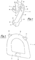
- the figure 1 shows the lashing arrangement in its working position, i.e. lashing of an object 3 on the surface of the floor 5 using a strap 14 by means of a hook 15 .
- the figure 2 shows the arrangement 1 in its retracted position in the chassis 7 flush with the loading floor surface 5.
- the lashing ring comprises a rounded stirrup part 16 for hooking the lashing means and a straight base 17 which connects the two ends of the stirrup.
- the base is cylindrical in shape and includes in its central area a flat part 19.
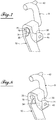
- the support for this ring as can be seen in particular on the figure 3 , consists of a yoke in the form of a band, the ends of which are configured as fixing lugs 21, 22 on a surface 24 of the carrying structure, which extends perpendicular to the loading floor, one 21 above the other 22 at a predetermined distance.
- the upper part of the yoke strip, which is adjacent to the loading floor is bent in the example shown by an angle of 180 degrees, forming at the top a semi-cylindrical housing 25 in which the cylindrical base of the ring can engage to allow pivoting of the ring in its stowed position as shown in figure 1 .
- the yoke defines with its fixing surface, below the housing 25, a space 26 allowing the displacement of the ring from its stowed out position in its retracted rest position, that is to say withdrawn in the support and chassis, in accordance with figure 2 .
- the yoke comprises an inclined part 28 which ends at the bottom by the fixing lug 22 and which is extended at the top by a vertical part 29 whose end portion is first bent at 30 by an angle of 90 degrees and then again by an angle of 90 degrees to form a vertical descending part 31 which ends in the fixing lug 21.
- This lug extends perpendicular to the vertical part 31.
- the semi-cylindrical housing 25 is formed by the internal surfaces of the curved portions 30 and 31.
- the terms "strip-shaped screed" do not necessarily mean that the screed is produced by folding a strip , but that it is a part comprising a succession of the parts indicated. This part can be made in any suitable manner, for example by molding, and in any suitable material.
- the vertical yoke part 29 is provided with a boss 34 which projects in the direction of the curved part facing 31.
- the upper surface of the boss is in the form of a circular arc having the same radius of curvature as the housing 25 while continuing the curvature thereof.
- This boss is located, relative to the width of the yoke, in the central part of the yoke part 29 at the level of the flat in the cylindrical base of the ring.
- the boss thus narrows the passage 35 between the cylindrical housing 25 and the space 26 below this housing, so that this passage is only slightly greater than the thickness of the base of the ring at the level of the flat , that is to say the thickness of the base perpendicular to the latter.
- the base can exit the housing 25 only when it is in an angular position in which the flat is located just above the passage, as will be explained later.
- the outer surface of the upper fixing lug 21 is in the form of a groove which is curved in a plane parallel to the fixing surface of the chassis, on the one hand and whose bottom is also curved, complementary to the diameter of the stirrup curvature and the diameter of the stirrup, so that the stirrup can be housed in this groove in its retracted position.
- the base of the ring is supported on a bearing surface 37 of the lower fixing lug 22.
- the inclined yoke part 28 has at the bottom, above its lug fixing 22 an external boss 39 on which can bear the upper part of the stirrup in the retracted position of the figure 12 .
- stirrup it can be seen that it has, on either side of the center line perpendicular to the base, at the level of the top of the stirrup, protuberances 42 which facilitate the grasping of the ring. stowage.
- this can be done by screws, namely, by three screws, the passage holes of which are indicated at 45.
- This fixing can also be carried out by welding .
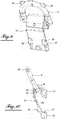
- FIG. 13A shows the lashing ring 9 in its lashing position, in which the base is engaged in the housing 25. In this position, the ring extends outward through a cutout 50 in the chassis 7 and is supported at 51 on the edge of this cut while being inclined at an angle of for example 30 degrees. Since the ring is in support, the operator who must hang the securing means at the top of the ring, no longer needs to hold it.
- the figure 13B shows the ring in another extended position in which it rests on the outer horizontal edge 32 of the cutout 50.
- the movement of the ring between these two positions is effected by pivoting of the ring and by rotation of the base in its housing 25. Only by raising the ring vertically, in the position shown in the figure 7 where the flat 19 is located practically perpendicular to the housing exit surface, that is to say the passage, and by exerting a slight rotation, the flat portion of the ring can be passed through the narrowing produced by the boss and through it in the space 26 below, as shown in the figure 8 . After the ring base has passed through the larger space below, the ring can be pivoted to its position shown in the illustration.
- the figure 14 shows the mounting of the support for the lashing arrangement on an IPN-shaped beam. As illustrated in the figures, the support is fixed either by screws or by welding on the profile blade.
- the support for the lashing ring may have any other suitable shape, provided that the housing for the base of the ring, of cylindrical shape over at least the major part of its periphery, and a part in the form of a flat, and the passage of width narrowed but slightly greater than the thickness of the base, perpendicular to the flat , so as to allow the passage of the base from its housing towards the displacement space situated below, only as a function of the angular position of the base relative to the passage.
- the groove for receiving the rounded part of the stirrup of the ring and the bearing surface of the base configured so as to ensure a retracted position of the ring without play can be produced in a way appropriate different.
Landscapes
- Engineering & Computer Science (AREA)
- Transportation (AREA)
- Mechanical Engineering (AREA)
- Fittings On The Vehicle Exterior For Carrying Loads, And Devices For Holding Or Mounting Articles (AREA)
- Clamps And Clips (AREA)
Claims (6)
- Festzurr-Anordnung für Gegenstände auf einer Oberfläche, insbesondere auf einem Ladeboden (5) eines Transportfahrzeugs für Fracht, des Typs, umfassend einen Festzurr- und Befestigungsring (9) eines Festzurrmittels (14) wie ein Gurt oder eine Kette, und einen Halter (10) in Form einer Abdeckung, die bestimmt ist, auf einer tragenden Struktur (7) befestigt zu sein und in welcher der Ring zwischen mindestens einer Festzurrposition und einer Ruheposition verlagerbar ist, wobei der Ring eine zylindrische gerade Basis umfasst, die in eine Aufnahme komplementärer Form zum Halter eingesetzt ist, welche das Schwenken des Rings in die Festzurrposition durch Rotation der Basis in der Aufnahme erlaubt, dadurch gekennzeichnet, dass die zylindrische Basis des Festzurrrings (9) einen zentralen Abschnitt mit Abflachung (19) aufweist und dass der Festzurrringhalter (10) in seinem Ende, das der Oberfläche des Ladebodens (5) benachbart ist, eine Aufnahme (25) für die Basis (17) umfasst, welche die Rotation derselben in dieser Aufnahme erlaubt, und unterhalb der Aufnahme einen Verlagerungsbereich (26) der Basis (17) und welche die Verlagerung des Rings in eine versenkte Verstauposition erlaubt, und dass die Aufnahme (25) vom Verlagerungsbereich (26) durch eine verengte Durchgangszone (35) der Basis zum Bereich (26) getrennt ist, die etwas breiter als die Basis im Abflachungsabschnitt (19) ist, senkrecht zu der Abflachung, um den Durchgang der Basis (17) von der Aufnahme (25) zum Verlagerungsbereich (26) nur dann zu erlauben, wenn sich die Basis in einer Position befindet, in welcher die Abflachung senkrecht zum Durchgang ausgerichtet ist.
- Festzurr-Anordnung nach Anspruch 1, dadurch gekennzeichnet, dass der Halter (10) des Festzurrrings in der Außenfläche seines oberen Endes eine Aufnahmenut (36) der Befestigungsspitze (16) des Rings und im Bereich seines unteren Endes eine Abstützoberfläche (37), auf welcher sich die Basis (17) ohne Spiel abstützt, wenn der Ring in seiner versenkten Position ist, aufweist.
- Festzurr-Anordnung nach den Ansprüchen 1 bis 2, dadurch gekennzeichnet, dass sich der Festzurrring, in seiner Festzurrposition, jenseits der Oberfläche eines Ladebodens (5) erstreckt, durch einen Ausschnitt (50) in der tragenden Struktur, gemäß einem in Bezug auf die Oberfläche des Ladebodens (5) vorher festgelegten Winkel, und dass der Ring in dieser Position von einem Abstützmittel (51) gehalten wird.
- Festzurr-Anordnung nach einem der Ansprüche 1 bis 3, dadurch gekennzeichnet, dass der Halter (10) des Festzurrrings (9) an einer Befestigungsoberfläche (24) durch Schrauben oder durch Schweißen befestigbar ist.
- Festzurr-Anordnung nach einem der Ansprüche 1 bis 4, dadurch gekennzeichnet, dass der Halter (10) des Festzurrrings (9) aus einer Abdeckung in Form eines Bands besteht, dessen Enden jeweils in einem Befestigungsfuß (21 oder 22) an einer Oberfläche (24) der tragenden Struktur enden, die senkrecht zur Oberfläche des Bodens (5) ist, wobei der obere Endteil in Nachbarschaft zu der Oberfläche des Bodens (5) zu der Befestigungsoberfläche gekrümmt ist, indem er an der Spitze die halbzylindrische Aufnahme (25) der zylindrischen Basis (17) des Rings (9) bildet, wohingegen das Abdeckungsband unterhalb der Aufnahme den Verlagerungsbereich (26) der Basis (9) bildet, der von der Aufnahme (25) durch den vom Abflachungsabschnitt (19) verengten Durchgang getrennt ist.
- Festzurr-Anordnung nach Anspruch 5, dadurch gekennzeichnet, dass der Halter (9) des Festzurrrings (10) in Form einer Abdeckung einen in Bezug auf die Befestigungsoberfläche (24) mittleren geneigten Abschnitt (28) umfasst, der unten mit dem unteren Befestigungsfuß (22) endet und der sich oben mit einem vertikalen Abschnitt (29) verlängert, dessen Endabschnitt (30, 31) in einem Winkel von 180 Grad gekrümmt ist und an seinem Ende den oberen Befestigungsfuß (21) trägt, der sich senkrecht zu diesem Ende und zu der Befestigungsoberfläche (24) erstreckt und auf seiner äußeren Oberfläche die Aufnahmenut der Spitze des Festzurrrings aufweist.
Priority Applications (1)
| Application Number | Priority Date | Filing Date | Title |
|---|---|---|---|
| PL17199391T PL3323676T3 (pl) | 2016-11-16 | 2017-10-31 | Układ zabezpieczający przedmioty na powierzchni, zwłaszcza podłogi ładunkowej pojazdu do przewozu ładunku |
Applications Claiming Priority (1)
| Application Number | Priority Date | Filing Date | Title |
|---|---|---|---|
| FR1661106A FR3058688B1 (fr) | 2016-11-16 | 2016-11-16 | Agencement d'arrimage d'objets sur une surface, notamment d'un plancher de chargement d'un vehicule de transport de cargaisons |
Publications (2)
| Publication Number | Publication Date |
|---|---|
| EP3323676A1 EP3323676A1 (de) | 2018-05-23 |
| EP3323676B1 true EP3323676B1 (de) | 2020-02-26 |
Family
ID=57909669
Family Applications (1)
| Application Number | Title | Priority Date | Filing Date |
|---|---|---|---|
| EP17199391.8A Active EP3323676B1 (de) | 2016-11-16 | 2017-10-31 | Festzurr-anordnung für gegenstände auf einer oberfläche, insbesondere einem ladeboden eines transportfahrzeugs für fracht |
Country Status (4)
| Country | Link |
|---|---|
| EP (1) | EP3323676B1 (de) |
| ES (1) | ES2793403T3 (de) |
| FR (1) | FR3058688B1 (de) |
| PL (1) | PL3323676T3 (de) |
Families Citing this family (2)
| Publication number | Priority date | Publication date | Assignee | Title |
|---|---|---|---|---|
| CN111609794B (zh) * | 2020-04-24 | 2022-04-22 | 北京控制工程研究所 | 一种基于双机械臂抓捕的目标卫星星箭对接环抓捕点定位方法 |
| DE202022105208U1 (de) * | 2022-09-15 | 2024-01-10 | Thiele Gmbh & Co Kg | Schwenkbarer Zurrpunkt für die Ladefläche eines Transportfahrzeuges |
Family Cites Families (3)
| Publication number | Priority date | Publication date | Assignee | Title |
|---|---|---|---|---|
| FR2782040B1 (fr) * | 1998-08-07 | 2000-10-06 | Pommier & Cie | Agencement d'anneau d'arrimage destine a etre encastre dans le bord de rive d'un vehicule tel qu'un porteur, une remorque ou semi-remorque |
| DE202006007916U1 (de) * | 2006-05-17 | 2006-08-24 | Koninklijke Nooteboom Trailers B.V. | Vorrichtung zum Befestigen von Ladung auf einer Ladefläche |
| DE202015100750U1 (de) * | 2015-02-17 | 2015-03-03 | Thiele Gmbh & Co. Kg | Zurrpunkt |
-
2016
- 2016-11-16 FR FR1661106A patent/FR3058688B1/fr not_active Expired - Fee Related
-
2017
- 2017-10-31 PL PL17199391T patent/PL3323676T3/pl unknown
- 2017-10-31 ES ES17199391T patent/ES2793403T3/es active Active
- 2017-10-31 EP EP17199391.8A patent/EP3323676B1/de active Active
Non-Patent Citations (1)
| Title |
|---|
| None * |
Also Published As
| Publication number | Publication date |
|---|---|
| FR3058688A1 (fr) | 2018-05-18 |
| ES2793403T3 (es) | 2020-11-13 |
| PL3323676T3 (pl) | 2020-11-02 |
| EP3323676A1 (de) | 2018-05-23 |
| FR3058688B1 (fr) | 2018-12-07 |
Similar Documents
| Publication | Publication Date | Title |
|---|---|---|
| EP2586648B1 (de) | System, das eine Gleitschiene für einen Fahrzeugsitz umfasst, und Halterung zur Befestigung an dieser Gleitschiene sowie Herstellungsverfahren eines solchen Systems | |
| EP3323676B1 (de) | Festzurr-anordnung für gegenstände auf einer oberfläche, insbesondere einem ladeboden eines transportfahrzeugs für fracht | |
| FR3083178A1 (fr) | Crochet d'arrimage de charge sur le plateau d'un vehicule de transport | |
| CH644312A5 (fr) | Chaine pour pneumatique. | |
| EP2890906B1 (de) | Buchse zur befestigung eines bolzens an einem träger und entsprechende anordnung | |
| FR2782040A1 (fr) | Agencement d'anneau d'arrimage destine a etre encastre dans le bord de rive d'un vehicule tel qu'un porteur, une remorque ou semi-remorque | |
| EP3658790B1 (de) | Mutterkäfigsystem mit einem mutterkäfig und einem träger, auf dem der käfig montiert werden soll | |
| EP1870602B1 (de) | Montageteil zur Verbindung von zwei Elementen miteinander, entsprechende Montagevorrichtung und Anwendung im Automobilbereich | |
| EP2678212A1 (de) | Vorrichtung zur befestigung eines reserverades eines fahrzeuges | |
| FR2966490A1 (fr) | Verrou a crochet muni d'un ressort perfectionne | |
| FR2974326A1 (fr) | Systeme de connexion pour la fixation d'un dispositif de portage | |
| EP3392086B1 (de) | Ringförmige festzurranordnung auf einer haltestruktur, wie eine einfassung oder einem boden, insbesondere zum beladen eines transportfahrzeugs | |
| EP2867098B1 (de) | Halterung zum fügen eines stossfängerhaut an eines fahrzeugbauteil | |
| FR2698592A1 (fr) | Agencement pour la fixation amovible d'un siège sur le support plancher d'un véhicule automobile. | |
| FR2725780A1 (fr) | Procede de fixation d'une buse sur un radiateur de refroidissement | |
| EP2341014B1 (de) | Modularer Bootshaken für Abdeckelement | |
| EP3168119A1 (de) | System zur befestigung eines zubehörs, insbesondere eines gepäcks, auf einem motorrad | |
| EP3678894B1 (de) | Befestigungsvorrichtung eines abnehmbaren sitzes an einem kraftfahrzeugboden | |
| FR2581933A1 (fr) | Chariot de transport, notamment pour la clientele de magasins a libre-service. | |
| FR3082592A1 (fr) | Bord de panneau conforme pour la reception d’une pince a ecrou. | |
| EP4169770A1 (de) | Regal eines warentransportfachs | |
| EP1907739B1 (de) | Anordnung zur anbringung unter einer befestigten halterung, wie kraftfahrzeug-gehäuseboden und verfahren zur benutzung derselben | |
| EP3119620B1 (de) | System zur kopplung einer reihe von trägern mit einem an der heckstruktur eines kraftfahrzeugs befestigten wirbelhaken | |
| EP2100782A2 (de) | Schlaufe mit geneigter Vorderseite für einen Sicherheitsgurt | |
| FR2915152A1 (fr) | Barre de maintien de charge pour vehicule utilitaire et ensemble de barres pour maintien de charge. |
Legal Events
| Date | Code | Title | Description |
|---|---|---|---|
| PUAI | Public reference made under article 153(3) epc to a published international application that has entered the european phase |
Free format text: ORIGINAL CODE: 0009012 |
|
| STAA | Information on the status of an ep patent application or granted ep patent |
Free format text: STATUS: THE APPLICATION HAS BEEN PUBLISHED |
|
| AK | Designated contracting states |
Kind code of ref document: A1 Designated state(s): AL AT BE BG CH CY CZ DE DK EE ES FI FR GB GR HR HU IE IS IT LI LT LU LV MC MK MT NL NO PL PT RO RS SE SI SK SM TR |
|
| AX | Request for extension of the european patent |
Extension state: BA ME |
|
| STAA | Information on the status of an ep patent application or granted ep patent |
Free format text: STATUS: REQUEST FOR EXAMINATION WAS MADE |
|
| 17P | Request for examination filed |
Effective date: 20180924 |
|
| RBV | Designated contracting states (corrected) |
Designated state(s): AL AT BE BG CH CY CZ DE DK EE ES FI FR GB GR HR HU IE IS IT LI LT LU LV MC MK MT NL NO PL PT RO RS SE SI SK SM TR |
|
| GRAP | Despatch of communication of intention to grant a patent |
Free format text: ORIGINAL CODE: EPIDOSNIGR1 |
|
| STAA | Information on the status of an ep patent application or granted ep patent |
Free format text: STATUS: GRANT OF PATENT IS INTENDED |
|
| INTG | Intention to grant announced |
Effective date: 20190913 |
|
| GRAS | Grant fee paid |
Free format text: ORIGINAL CODE: EPIDOSNIGR3 |
|
| GRAA | (expected) grant |
Free format text: ORIGINAL CODE: 0009210 |
|
| STAA | Information on the status of an ep patent application or granted ep patent |
Free format text: STATUS: THE PATENT HAS BEEN GRANTED |
|
| AK | Designated contracting states |
Kind code of ref document: B1 Designated state(s): AL AT BE BG CH CY CZ DE DK EE ES FI FR GB GR HR HU IE IS IT LI LT LU LV MC MK MT NL NO PL PT RO RS SE SI SK SM TR |
|
| REG | Reference to a national code |
Ref country code: GB Ref legal event code: FG4D Free format text: NOT ENGLISH |
|
| REG | Reference to a national code |
Ref country code: CH Ref legal event code: EP |
|
| REG | Reference to a national code |
Ref country code: AT Ref legal event code: REF Ref document number: 1237217 Country of ref document: AT Kind code of ref document: T Effective date: 20200315 |
|
| REG | Reference to a national code |
Ref country code: IE Ref legal event code: FG4D Free format text: LANGUAGE OF EP DOCUMENT: FRENCH |
|
| REG | Reference to a national code |
Ref country code: DE Ref legal event code: R096 Ref document number: 602017012208 Country of ref document: DE |
|
| REG | Reference to a national code |
Ref country code: NL Ref legal event code: FP |
|
| PG25 | Lapsed in a contracting state [announced via postgrant information from national office to epo] |
Ref country code: NO Free format text: LAPSE BECAUSE OF FAILURE TO SUBMIT A TRANSLATION OF THE DESCRIPTION OR TO PAY THE FEE WITHIN THE PRESCRIBED TIME-LIMIT Effective date: 20200526 Ref country code: FI Free format text: LAPSE BECAUSE OF FAILURE TO SUBMIT A TRANSLATION OF THE DESCRIPTION OR TO PAY THE FEE WITHIN THE PRESCRIBED TIME-LIMIT Effective date: 20200226 Ref country code: RS Free format text: LAPSE BECAUSE OF FAILURE TO SUBMIT A TRANSLATION OF THE DESCRIPTION OR TO PAY THE FEE WITHIN THE PRESCRIBED TIME-LIMIT Effective date: 20200226 |
|
| REG | Reference to a national code |
Ref country code: LT Ref legal event code: MG4D |
|
| PG25 | Lapsed in a contracting state [announced via postgrant information from national office to epo] |
Ref country code: BG Free format text: LAPSE BECAUSE OF FAILURE TO SUBMIT A TRANSLATION OF THE DESCRIPTION OR TO PAY THE FEE WITHIN THE PRESCRIBED TIME-LIMIT Effective date: 20200526 Ref country code: IS Free format text: LAPSE BECAUSE OF FAILURE TO SUBMIT A TRANSLATION OF THE DESCRIPTION OR TO PAY THE FEE WITHIN THE PRESCRIBED TIME-LIMIT Effective date: 20200626 Ref country code: SE Free format text: LAPSE BECAUSE OF FAILURE TO SUBMIT A TRANSLATION OF THE DESCRIPTION OR TO PAY THE FEE WITHIN THE PRESCRIBED TIME-LIMIT Effective date: 20200226 Ref country code: LV Free format text: LAPSE BECAUSE OF FAILURE TO SUBMIT A TRANSLATION OF THE DESCRIPTION OR TO PAY THE FEE WITHIN THE PRESCRIBED TIME-LIMIT Effective date: 20200226 Ref country code: GR Free format text: LAPSE BECAUSE OF FAILURE TO SUBMIT A TRANSLATION OF THE DESCRIPTION OR TO PAY THE FEE WITHIN THE PRESCRIBED TIME-LIMIT Effective date: 20200527 Ref country code: HR Free format text: LAPSE BECAUSE OF FAILURE TO SUBMIT A TRANSLATION OF THE DESCRIPTION OR TO PAY THE FEE WITHIN THE PRESCRIBED TIME-LIMIT Effective date: 20200226 |
|
| PG25 | Lapsed in a contracting state [announced via postgrant information from national office to epo] |
Ref country code: SK Free format text: LAPSE BECAUSE OF FAILURE TO SUBMIT A TRANSLATION OF THE DESCRIPTION OR TO PAY THE FEE WITHIN THE PRESCRIBED TIME-LIMIT Effective date: 20200226 Ref country code: LT Free format text: LAPSE BECAUSE OF FAILURE TO SUBMIT A TRANSLATION OF THE DESCRIPTION OR TO PAY THE FEE WITHIN THE PRESCRIBED TIME-LIMIT Effective date: 20200226 Ref country code: DK Free format text: LAPSE BECAUSE OF FAILURE TO SUBMIT A TRANSLATION OF THE DESCRIPTION OR TO PAY THE FEE WITHIN THE PRESCRIBED TIME-LIMIT Effective date: 20200226 Ref country code: EE Free format text: LAPSE BECAUSE OF FAILURE TO SUBMIT A TRANSLATION OF THE DESCRIPTION OR TO PAY THE FEE WITHIN THE PRESCRIBED TIME-LIMIT Effective date: 20200226 Ref country code: SM Free format text: LAPSE BECAUSE OF FAILURE TO SUBMIT A TRANSLATION OF THE DESCRIPTION OR TO PAY THE FEE WITHIN THE PRESCRIBED TIME-LIMIT Effective date: 20200226 Ref country code: PT Free format text: LAPSE BECAUSE OF FAILURE TO SUBMIT A TRANSLATION OF THE DESCRIPTION OR TO PAY THE FEE WITHIN THE PRESCRIBED TIME-LIMIT Effective date: 20200719 Ref country code: RO Free format text: LAPSE BECAUSE OF FAILURE TO SUBMIT A TRANSLATION OF THE DESCRIPTION OR TO PAY THE FEE WITHIN THE PRESCRIBED TIME-LIMIT Effective date: 20200226 Ref country code: CZ Free format text: LAPSE BECAUSE OF FAILURE TO SUBMIT A TRANSLATION OF THE DESCRIPTION OR TO PAY THE FEE WITHIN THE PRESCRIBED TIME-LIMIT Effective date: 20200226 |
|
| REG | Reference to a national code |
Ref country code: ES Ref legal event code: FG2A Ref document number: 2793403 Country of ref document: ES Kind code of ref document: T3 Effective date: 20201113 |
|
| REG | Reference to a national code |
Ref country code: AT Ref legal event code: MK05 Ref document number: 1237217 Country of ref document: AT Kind code of ref document: T Effective date: 20200226 |
|
| REG | Reference to a national code |
Ref country code: DE Ref legal event code: R097 Ref document number: 602017012208 Country of ref document: DE |
|
| PLBE | No opposition filed within time limit |
Free format text: ORIGINAL CODE: 0009261 |
|
| STAA | Information on the status of an ep patent application or granted ep patent |
Free format text: STATUS: NO OPPOSITION FILED WITHIN TIME LIMIT |
|
| PG25 | Lapsed in a contracting state [announced via postgrant information from national office to epo] |
Ref country code: AT Free format text: LAPSE BECAUSE OF FAILURE TO SUBMIT A TRANSLATION OF THE DESCRIPTION OR TO PAY THE FEE WITHIN THE PRESCRIBED TIME-LIMIT Effective date: 20200226 |
|
| 26N | No opposition filed |
Effective date: 20201127 |
|
| PG25 | Lapsed in a contracting state [announced via postgrant information from national office to epo] |
Ref country code: SI Free format text: LAPSE BECAUSE OF FAILURE TO SUBMIT A TRANSLATION OF THE DESCRIPTION OR TO PAY THE FEE WITHIN THE PRESCRIBED TIME-LIMIT Effective date: 20200226 |
|
| PGFP | Annual fee paid to national office [announced via postgrant information from national office to epo] |
Ref country code: BE Payment date: 20201029 Year of fee payment: 4 |
|
| REG | Reference to a national code |
Ref country code: CH Ref legal event code: PL |
|
| PG25 | Lapsed in a contracting state [announced via postgrant information from national office to epo] |
Ref country code: LU Free format text: LAPSE BECAUSE OF NON-PAYMENT OF DUE FEES Effective date: 20201031 Ref country code: MC Free format text: LAPSE BECAUSE OF FAILURE TO SUBMIT A TRANSLATION OF THE DESCRIPTION OR TO PAY THE FEE WITHIN THE PRESCRIBED TIME-LIMIT Effective date: 20200226 |
|
| PG25 | Lapsed in a contracting state [announced via postgrant information from national office to epo] |
Ref country code: LI Free format text: LAPSE BECAUSE OF NON-PAYMENT OF DUE FEES Effective date: 20201031 Ref country code: CH Free format text: LAPSE BECAUSE OF NON-PAYMENT OF DUE FEES Effective date: 20201031 |
|
| PG25 | Lapsed in a contracting state [announced via postgrant information from national office to epo] |
Ref country code: IE Free format text: LAPSE BECAUSE OF NON-PAYMENT OF DUE FEES Effective date: 20201031 |
|
| PG25 | Lapsed in a contracting state [announced via postgrant information from national office to epo] |
Ref country code: TR Free format text: LAPSE BECAUSE OF FAILURE TO SUBMIT A TRANSLATION OF THE DESCRIPTION OR TO PAY THE FEE WITHIN THE PRESCRIBED TIME-LIMIT Effective date: 20200226 Ref country code: MT Free format text: LAPSE BECAUSE OF FAILURE TO SUBMIT A TRANSLATION OF THE DESCRIPTION OR TO PAY THE FEE WITHIN THE PRESCRIBED TIME-LIMIT Effective date: 20200226 Ref country code: CY Free format text: LAPSE BECAUSE OF FAILURE TO SUBMIT A TRANSLATION OF THE DESCRIPTION OR TO PAY THE FEE WITHIN THE PRESCRIBED TIME-LIMIT Effective date: 20200226 |
|
| REG | Reference to a national code |
Ref country code: BE Ref legal event code: MM Effective date: 20211031 |
|
| PG25 | Lapsed in a contracting state [announced via postgrant information from national office to epo] |
Ref country code: MK Free format text: LAPSE BECAUSE OF FAILURE TO SUBMIT A TRANSLATION OF THE DESCRIPTION OR TO PAY THE FEE WITHIN THE PRESCRIBED TIME-LIMIT Effective date: 20200226 Ref country code: AL Free format text: LAPSE BECAUSE OF FAILURE TO SUBMIT A TRANSLATION OF THE DESCRIPTION OR TO PAY THE FEE WITHIN THE PRESCRIBED TIME-LIMIT Effective date: 20200226 |
|
| PG25 | Lapsed in a contracting state [announced via postgrant information from national office to epo] |
Ref country code: BE Free format text: LAPSE BECAUSE OF NON-PAYMENT OF DUE FEES Effective date: 20211031 |
|
| P01 | Opt-out of the competence of the unified patent court (upc) registered |
Effective date: 20230518 |
|
| PGFP | Annual fee paid to national office [announced via postgrant information from national office to epo] |
Ref country code: PL Payment date: 20250925 Year of fee payment: 9 |
|
| PGFP | Annual fee paid to national office [announced via postgrant information from national office to epo] |
Ref country code: NL Payment date: 20251024 Year of fee payment: 9 |
|
| PGFP | Annual fee paid to national office [announced via postgrant information from national office to epo] |
Ref country code: DE Payment date: 20251030 Year of fee payment: 9 |
|
| PGFP | Annual fee paid to national office [announced via postgrant information from national office to epo] |
Ref country code: GB Payment date: 20251024 Year of fee payment: 9 |
|
| PGFP | Annual fee paid to national office [announced via postgrant information from national office to epo] |
Ref country code: IT Payment date: 20251030 Year of fee payment: 9 |
|
| PGFP | Annual fee paid to national office [announced via postgrant information from national office to epo] |
Ref country code: FR Payment date: 20251006 Year of fee payment: 9 |
|
| PGFP | Annual fee paid to national office [announced via postgrant information from national office to epo] |
Ref country code: ES Payment date: 20251103 Year of fee payment: 9 |