EP3323708B1 - Défense de proue - Google Patents
Défense de proue Download PDFInfo
- Publication number
- EP3323708B1 EP3323708B1 EP17199165.6A EP17199165A EP3323708B1 EP 3323708 B1 EP3323708 B1 EP 3323708B1 EP 17199165 A EP17199165 A EP 17199165A EP 3323708 B1 EP3323708 B1 EP 3323708B1
- Authority
- EP
- European Patent Office
- Prior art keywords
- fender
- bow
- support blocks
- front side
- skidable
- Prior art date
- Legal status (The legal status is an assumption and is not a legal conclusion. Google has not performed a legal analysis and makes no representation as to the accuracy of the status listed.)
- Active
Links
Images
Classifications
-
- B—PERFORMING OPERATIONS; TRANSPORTING
- B63—SHIPS OR OTHER WATERBORNE VESSELS; RELATED EQUIPMENT
- B63B—SHIPS OR OTHER WATERBORNE VESSELS; EQUIPMENT FOR SHIPPING
- B63B59/00—Hull protection specially adapted for vessels; Cleaning devices specially adapted for vessels
- B63B59/02—Fenders integral with waterborne vessels or specially adapted therefor, e.g. fenders forming part of the hull or incorporated in the hull; Rubbing-strakes
-
- B—PERFORMING OPERATIONS; TRANSPORTING
- B63—SHIPS OR OTHER WATERBORNE VESSELS; RELATED EQUIPMENT
- B63B—SHIPS OR OTHER WATERBORNE VESSELS; EQUIPMENT FOR SHIPPING
- B63B21/00—Tying-up; Shifting, towing, or pushing equipment; Anchoring
-
- B—PERFORMING OPERATIONS; TRANSPORTING
- B63—SHIPS OR OTHER WATERBORNE VESSELS; RELATED EQUIPMENT
- B63B—SHIPS OR OTHER WATERBORNE VESSELS; EQUIPMENT FOR SHIPPING
- B63B27/00—Arrangement of ship-based loading or unloading equipment for cargo or passengers
- B63B27/30—Arrangement of ship-based loading or unloading equipment for transfer at sea between ships or between ships and off-shore structures
-
- B—PERFORMING OPERATIONS; TRANSPORTING
- B63—SHIPS OR OTHER WATERBORNE VESSELS; RELATED EQUIPMENT
- B63B—SHIPS OR OTHER WATERBORNE VESSELS; EQUIPMENT FOR SHIPPING
- B63B27/00—Arrangement of ship-based loading or unloading equipment for cargo or passengers
- B63B27/14—Arrangement of ship-based loading or unloading equipment for cargo or passengers of ramps, gangways or outboard ladders ; Pilot lifts
Definitions
- the present invention relates to a bow fender for service vessels for the offshore wind industry and oil and gas market, comprising an elongated fender equipped with two in longitudinal and opposite directions movable support blocks, wherein said support blocks are longitudinally skidable on a front side of the rubber fender under the influence of a pressure actuator.
- Offshore wind turbines are normally gathered in wind farms placed on the continental shelf with reduced water dept. Higher wind speeds are available offshore compared to land, and supplies more energy.
- Offshore wind power refers to the construction of wind farms in bodies of water to generate electricity from wind. Offshore wind power utilizes traditional fixed-bottom wind turbine technologies, as well as deep-water areas utilizing floating wind turbines.
- the service crews are normally brought from ports or accommodation vessels with service vessels, and the service personnel embark and disembark between the service vessel and the turbines or platforms.
- Each turbine has two vertical poles/fender bars to protect the turbine while the service vessel approach the turbine and allows the service personnel to use the turbines ladder between the two poles for embarking and disembarking. With the vessels engines/propellers the vessel's transverse bow-fender is pushed against the poles.
- the challenge is to keep the bow of the vessel steady when the service personnel embark and disembark in rougher sea conditions.
- a hydraulic clamping system that is mounted on the deck of the crew transfer vessel. Its main elements are two hydraulic arms which can rotate around a vertical axis. At their front-end a hydraulic clamp is mounted which can be swung around the vertical fender bars of the wind turbine, and by activating two hydraulic rams they pull the vessel's fender against the fender bars with a preset force. The resulting friction stabilizes the position of the vessel.
- GB 2476858 A discloses an apparatus for stabilizing a floating craft against a stationary structure.
- the apparatus comprises means of attaching the apparatus to a floating craft, an elongate fender comprising a structure contacting face, and at least two jaws, each comprising a front face and a structure contacting surface.
- At least one jaw is movable from a first position to a second position and vice versa, in order that said jaws may be positioned in a first open position where the structure contacting surfaces of the jaws are relatively far apart and a second closed position wherein the structure contacting surfaces of the jaws are relatively close together.
- the apparatus is positioned such that a suitably sized part of the stationary structure is placed between the jaws, the said jaws can then be brought into the closed position, thereby creating craft stabilizing contact between the structure contacting surfaces of the jaws and the structure.
- EP 2520485 A1 discloses a system for mooring a vessel against a stationary object, for example the mast of a wind turbine erected in water.
- the stationary object comprises at least one substantially vertical bumper bar which is attached to the stationary object by means of an extension.
- the vessel comprises a hull, an engine for propelling the vessel, and a buffer body which protrudes in relation to the hull.
- the bumper bar comprises a substantially vertical, inside guide track which substantially faces the stationary object and a substantially vertical, outside guide track which substantially faces away from the stationary object.
- the vessel comprises at least one engagement arm which at one end is provided with an engagement member.
- the engagement arm can be moved in relation to the hull between a mooring state, in which the engagement member engages on the inside guide track of the bumper bar and is vertically displaceable along this, and a release state, in which the engagement member is out of engagement with the inside guide track.
- the buffer body in the mooring state engages on the outside guide track of the bumper bar and is vertically displaceable along this.
- the inside guide track protrudes sideways in relation to an adjacent part of the extension of the bumper bar such that the engagement member of the engagement arm in the mooring state can be moved past the extension on vertical displacement along the inside guide track of the bumper bar.
- An object of the present invention is to provide an improved alternative and simplified solution with an integrated solution in the bow fender, making the vessel's bow fender to stay quiet while the service crew embark and disembark in rough sea conditions.
- the present invention also provides a solution which makes it easy to center the bow of the vessel to the correct positioned, which save time and increase the safety.
- a bow fender on a crew transfer vessel comprising an elongated fender equipped with two in longitudinal and opposite directions movable support blocks, wherein said support blocks are longitudinally skidable on a front side of the fender under the influence of a pressure actuator, wherein each of said support blocks comprises a U-shaped base plate, which at least partially envelopes the fender, and with an interior width between respective side faces of the U-shaped base plate corresponding to the height of the fender.
- Said base plate can comprise at least one internal connection arm extending though a longitudinal slit in the front side of the fender, and which is connected to the pressure actuator, such as a hydraulic cylinder.
- the pressure actuator can be resting in an open box placed in a back side of the fender, and the pressure actuator and the connection arm of the support block can be connected to a skid plate, said skid plate being skidable in respective side slots in the box.
- Each of said support blocks can comprise a rubber covering, said rubber covering may be placed on an outer side of the base plate.
- Two boxes with a hydraulic cylinder can be placed on opposite sides to a center line of the fender, and connected to each of said support blocks.
- the support blocks can be skidable to an extracted position and a retracted position on the front side of the elongated fender.
- the support blocks When said support blocks are in the retracted position on the front side of the fender, the support blocks are preferable clamping against an object, in order to prevent movement of the bow fender in relation to said object.
- the object can be two vertical fender bars on an offshore wind turbine foundation.
- Said support blocks can comprise respective connection arms, which extends through longitudinal slits in the front side of the fender, and the connection arms of each support block can be connected to a respective hydraulic actuator extending through a cavity in the fender.
- the bow fender is connected to a control system on the vessel's bridge, in order to activate the bow fender to retract or extract the support blocks.
- the fender can in the middle of the front side comprise a protruding, ticker part, and the two in longitudinal and opposite directions movable support blocks are skidable on each side of the ticker middle part.
- the elongated fender can be made of rubber, or the elongated fender can be made of plastic.
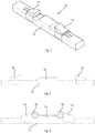
- the bow fender 10 comprises an elongated rubber fender 12. In the middle of the rubber fender 12 there is a ticker part 36 on the front side 12a, which is pressed against a ladder 54 of a wind turbine foundation 52.
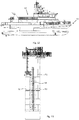
- the bow fender 10 is mounted on the bow of a vessel 60, such as a crew transfer vessel, with the ticker part 36 facing forward.
- the elongated fender 12 is disclosed as made of rubber, but the elongated fender 12 can be made of plastic or other suitable material.
- the bow fender 10 according to the invention is disclosed in relation to a wind turbine foundation, but may of course be used with any similar offshore construction.
- Such a bow fender 10 can for instance be approximately 10m long, and with a thickness of 45cm and a height of 65cm.
- Support poles 50, or fender bars, on a typical wind turbine foundation 52 have a diameter of 33cm, and a center distance of for instance 1,8m.
- the ticker part 36 of the bow fender is accommodated between the support poles 50 when the vessel 60 is pushing forward.
- the thrust by the vessel may for instance be between 8 to 10 tons.
- the bow fender 10 is equipped with two support blocks 14, or fender clamps/shoes, which can be pushed against the outside of each support pole 50.
- the support blocks 14 can each be pushed against the poles 50 with a force of for instance 5 tons, which together with the forward trust from the vessel makes the bow of the vessel steady with respect to the ladder 54, and allowing the service crew to enter the construction safely. Due to the high forces, the bow fender can for instance be compressed approximately 10cm in the area where the bow fender meets the poles. If the fender 12 is made of thick rubber, such a compression is unproblematic.
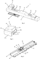
- the support blocks 14 or fender clamps/shoes are made of a baseplate 20, which at least partly envelopes the rubber fender 12.
- a rubber fender 12 normally has a square or rectangular cross-section, and the baseplate 20 is thus formed in a corresponding U-shape.
- the baseplate may have a similar shape.
- An interior width between respective side faces 20a,20b of the baseplate 20 corresponds preferable to the height of the rubber fender 12.
- the support blocks 14 are thus skidable in longitudinal directions back and forth on the front side 12a of the rubber fender 12.
- the side faces 20a,20b will normally not completely cover the rubber fender 12 to allow for compression of the rubber fender 12.
- the support blocks 14 comprises a rubber covering 30, which is placed externally on an outer side 20c of the base plate 20.
- the baseplate 20 can have a height of 65cm, similar to the height of the rubber fender 12, and a length of 80cm.
- the base part of the rubber covering 30 can have similar length of 80cm and a thickness of 20cm.
- the rubber covering 30 may extend quite a bit passed the baseplate 20, in the direction towards the middle of the rubber fender 12.
- the rubber covering 30 may extend passed the baseplate 20 with 20cm.
- the front face 30a of the rubber covering 30, i.e. the part that is pressed against the support poles 50 on the wind turbine foundation 54, can have an arched surface similar to the radius of the poles.
- the front part can also be thicker than the rear part.
- the base plate 20 comprise on the inside one or two downward directed internal connections arm 22, which extend through longitudinal slits 16 in the front side 12a of the rubber fender 12.
- An open box with a hydraulic actuator 18, such as a hydraulic cylinder, is placed in a cavity 40 in the back side 12b of the rubber fender 12.
- the box is secured to the rubber fender 12, and can also be secured to the vessel's bow.
- the connection arms 22 extending down through the slits 16 are connected to the hydraulic actuator 18 via a skid plate 26 placed in the bottom of the box.
- the skid plate 26 has a connection 34 for connection of a rod part of the actuator 18, and a connection 32 for connection of each of the connection arms 22.
- the box 24 may comprise respective side slots 28.
- the sides of the skid plate 26 may comprise a glider 38 to ease movement in the side slots 28.
- Said glider 38 can be made of brass, and the side slots 28 can be covered by a nonstick material, such as Teflon.
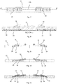
- Figures 9-11 show an alternative and simplified embodiment of the bow fender 10 according to the invention.
- the hydraulic actuator 18 is placed biased in a somewhat larger slit or cavity 45 in a back side 12b of the rubber fender, and is directly connected to the connection arms 22 to push and pull on the support blocks 14.
- Figure 9 shows the support blocks 14 in a retracted position.
- Figure 10 shows the support blocks 14 in an extracted position.
- Figure 11 shows the support blocks 14 in both retracted and extracted positions.
- the rubber covering 12 may be equipped with other slits (not shown) than the slits for the connection arms 22, and the interior of the base plate 20 can have corresponding protrusions to further restrict unwanted tilting or other movement of the base plate.
- the bow fender 10 is preferable connected to a control system on the vessel's bridge, in order to activate the bow fender to retract or extract the support blocks 14.
Landscapes
- Chemical & Material Sciences (AREA)
- Engineering & Computer Science (AREA)
- Combustion & Propulsion (AREA)
- Mechanical Engineering (AREA)
- Ocean & Marine Engineering (AREA)
- Wind Motors (AREA)
- Body Structure For Vehicles (AREA)
Claims (12)
- Défense de proue (10) pour un navire de transfert d'équipage, comprenant une défense allongée (12) équipée de deux blocs de support (14) mobiles dans une direction longitudinale et dans une direction opposée, dans laquelle lesdits blocs de support (14) peuvent glisser de manière longitudinale sur un côté avant (12a) de la défense (12) sous l'influence d'un actionneur de pression (18),
caractérisé en ce que chacun desdits blocs de support (14) comprend une plaque de base en forme de U (20), qui enveloppe au moins partiellement la défense (12), et avec une largeur intérieure entre des faces latérales respectives (20a, 20b) de la plaque de base en forme de U (20) correspondant à la hauteur de la défense (12). - Défense de proue (10) selon la revendication 1, dans laquelle ladite plaque de base (20) comprend au moins un bras de raccordement interne (22) s'étendant à travers une fente longitudinale (16) sur le côté avant (12a) de la défense (12), et qui est raccordé à l'actionneur de pression (18), comme un cylindre hydraulique.
- Défense de proue (10) selon la revendication 1 à 2, dans laquelle l'actionneur de pression (18) s'appuie sur un boîtier ouvert (24) placé sur le côté arrière (12b) de la défense (12), et l'actionneur de pression (18) et le bras de connexion (22) du bloc de support (14) sont raccordés à une plaque de protection (26), ladite plaque de protection (26) pouvant glisser dans des fentes latérales respectives (28) dans le boîtier (24).
- Défense de proue (10) selon la revendication 1, dans laquelle chacun desdits blocs de support (14) comprend une couverture en caoutchouc (30), ladite couverture en caoutchouc (30) est située sur un côté extérieur (20c) de la plaque de base (20).
- Défense de proue (10) selon la revendication 1 à 4, dans laquelle deux boîtiers (24) avec un cylindre hydraulique (18) sont placés sur des côtés opposés à une ligne centrale de la défense (12), et raccordés à chacun desdits blocs de support (14).
- Défense de proue (10) selon la revendication 1, dans laquelle lesdits blocs de support (14) peuvent glisser vers une position extraite et une position rétractée sur le côté avant (12a) de la défense allongée (12).
- Défense de proue (10) selon la revendication 6, dans laquelle, lorsque lesdits blocs de support (14) sont dans la position rétractée sur le côté avant (12a) de la défense (12), les blocs de support (14) sont serrés contre un objet, afin d'empêcher le mouvement de la défense de proue (10) relativement audit objet.
- Défense de proue (10) selon la revendication 7, dans laquelle ledit objet est constitué de deux barres de défense verticales (50) sur une fondation d'éolienne offshore (52).
- Défense de proue (10) selon la revendication 1, dans laquelle lesdits blocs de support (14) comprennent des bras de raccordement respectifs (22), qui s'étendent à travers des fentes longitudinales (16) sur le côté avant (12a) de la défense (12), et les bras de raccordement (22) de chaque bloc de support (14) sont raccordés à un actionneur hydraulique respectif (18) s'étendant à travers une cavité (45) dans la défense (12).
- Défense de proue (10) selon les revendications 1 à 9, dans laquelle la défense de proue (10) est raccordée à un système de commande sur le pont du vaisseau, afin d'activer la défense de proue (10) afin de rétracter ou d'extraire les blocs de support (14).
- Défense de proue (10) selon les revendications 1 à 10, dans laquelle la défense (12) au centre du côté avant (12a) comprend une partie de bandeau saillante (36), et les deux blocs de support (14) mobiles dans la direction longitudinale et la direction opposée peuvent glisser de chaque côté de la partie centrale de bandeau (36).
- Défense de proue (10) selon les revendications 1 à 11, dans laquelle la défense allongée (12) est réalisée en caoutchouc, ou la défense allongée (12) est réalisée en plastique.
Applications Claiming Priority (1)
| Application Number | Priority Date | Filing Date | Title |
|---|---|---|---|
| NO20161849A NO20161849A1 (en) | 2016-11-22 | 2016-11-22 | Bow fender |
Publications (2)
| Publication Number | Publication Date |
|---|---|
| EP3323708A1 EP3323708A1 (fr) | 2018-05-23 |
| EP3323708B1 true EP3323708B1 (fr) | 2019-05-22 |
Family
ID=60191261
Family Applications (1)
| Application Number | Title | Priority Date | Filing Date |
|---|---|---|---|
| EP17199165.6A Active EP3323708B1 (fr) | 2016-11-22 | 2017-10-30 | Défense de proue |
Country Status (3)
| Country | Link |
|---|---|
| EP (1) | EP3323708B1 (fr) |
| DK (1) | DK3323708T3 (fr) |
| NO (1) | NO20161849A1 (fr) |
Families Citing this family (4)
| Publication number | Priority date | Publication date | Assignee | Title |
|---|---|---|---|---|
| EP3715239A1 (fr) | 2019-03-25 | 2020-09-30 | Offshore Windservice A/S | Récipient doté d'une protection inclinable |
| GB2592028B (en) * | 2020-02-12 | 2023-06-21 | Bmt Ltd | Cassette assembly, waterborne vessel and method of servicing a water-accessible structure |
| GB2592029B (en) * | 2020-02-12 | 2023-06-28 | Bmt Ltd | Cassette assembly, waterborne vessel and method of servicing a water-accessible structure |
| CN116620498A (zh) * | 2023-03-10 | 2023-08-22 | 福建海电运维科技股份有限公司 | 一种风电运维船顶靠橡胶碰垫 |
Family Cites Families (3)
| Publication number | Priority date | Publication date | Assignee | Title |
|---|---|---|---|---|
| GB2476858C (en) * | 2010-11-19 | 2021-07-21 | Stephen Mattey Ronald | Jaw apparatus for stabilising a floating craft against a stationary structure |
| NL2006710C2 (nl) * | 2011-05-03 | 2012-11-06 | Presign Holding B V | Systeem en werkwijze voor het aanmeren van een drijvend vaartuig tegen een stationair object. |
| EP2923941A1 (fr) * | 2014-03-26 | 2015-09-30 | World Marine Offshore A/S | Dispositif amortisseur hydraulique maritime |
-
2016
- 2016-11-22 NO NO20161849A patent/NO20161849A1/no unknown
-
2017
- 2017-10-30 EP EP17199165.6A patent/EP3323708B1/fr active Active
- 2017-10-30 DK DK17199165.6T patent/DK3323708T3/da active
Non-Patent Citations (1)
| Title |
|---|
| None * |
Also Published As
| Publication number | Publication date |
|---|---|
| DK3323708T3 (da) | 2019-06-24 |
| NO341915B1 (en) | 2018-02-19 |
| NO20161849A1 (en) | 2018-02-19 |
| EP3323708A1 (fr) | 2018-05-23 |
Similar Documents
| Publication | Publication Date | Title |
|---|---|---|
| EP3323708B1 (fr) | Défense de proue | |
| NL1009277C2 (nl) | Werkwijze en inrichting voor het nauwkeurig plaatsen van relatief zware voorwerpen op en wegnemen van zware voorwerpen van de zeebodem. | |
| EP2316721B1 (fr) | Procédé de stabilisation d'un navire contre un objet immobile | |
| KR101577157B1 (ko) | 부체식 풍력 발전 장치 및 부체식 풍력 발전 장치의 계류 방법 | |
| EP2487102B1 (fr) | Appareil d'accès pour le transfert depuis des récipients vers des structures fixes | |
| JP2015530315A (ja) | 浮上式プラットフォームの移動及び設置用船体、およびその船体を用いた浮上式プラットフォームの移動及び設置方法 | |
| US6276875B1 (en) | Method and transporter for installation or removal of a jacket for an offshore platform | |
| GB2483401A (en) | Pivoting deck vessel for allowing transfer to a fixed structure | |
| EP2923941A1 (fr) | Dispositif amortisseur hydraulique maritime | |
| CN110546064A (zh) | 靠泊装置船舶 | |
| EP3715239A1 (fr) | Récipient doté d'une protection inclinable | |
| US11760447B2 (en) | System for stabilizing a vessel against a stationary object | |
| EP2661392B1 (fr) | T.d.d. (dispositif d'accostage à tube) | |
| NZ747817A (en) | Marine vessel | |
| EP2623413B1 (fr) | Procédé et système de fourniture d'accès entre un navire flottant et une structure marine | |
| GB2520094A (en) | Pole Engagement device for marine vessels | |
| WO2022019801A1 (fr) | Procédé de transport d'iceberg de grande taille | |
| FR3016341A1 (fr) | Dispositif de mat telescopique de navire | |
| EP3243734A1 (fr) | Ensemble d'un bateau et un module flottant | |
| GB2475085A (en) | Pivoting deck vessel for allowing transfer to a fixed structure | |
| JP2015054623A (ja) | プッシャバージの連結昇降装置、プッシャバージ、及びバージ | |
| EP3254946B1 (fr) | Navire adapte a la manipulation d'une ancre | |
| EP2844541B1 (fr) | Navire équipé d'un système de tirage vertical | |
| NL2014304B1 (en) | Tugboat provided with a carrousel-type towing system. | |
| US20250010959A1 (en) | System of articulated fins for a boat |
Legal Events
| Date | Code | Title | Description |
|---|---|---|---|
| PUAI | Public reference made under article 153(3) epc to a published international application that has entered the european phase |
Free format text: ORIGINAL CODE: 0009012 |
|
| STAA | Information on the status of an ep patent application or granted ep patent |
Free format text: STATUS: THE APPLICATION HAS BEEN PUBLISHED |
|
| AK | Designated contracting states |
Kind code of ref document: A1 Designated state(s): AL AT BE BG CH CY CZ DE DK EE ES FI FR GB GR HR HU IE IS IT LI LT LU LV MC MK MT NL NO PL PT RO RS SE SI SK SM TR |
|
| AX | Request for extension of the european patent |
Extension state: BA ME |
|
| STAA | Information on the status of an ep patent application or granted ep patent |
Free format text: STATUS: REQUEST FOR EXAMINATION WAS MADE |
|
| 17P | Request for examination filed |
Effective date: 20181123 |
|
| RBV | Designated contracting states (corrected) |
Designated state(s): AL AT BE BG CH CY CZ DE DK EE ES FI FR GB GR HR HU IE IS IT LI LT LU LV MC MK MT NL NO PL PT RO RS SE SI SK SM TR |
|
| GRAP | Despatch of communication of intention to grant a patent |
Free format text: ORIGINAL CODE: EPIDOSNIGR1 |
|
| STAA | Information on the status of an ep patent application or granted ep patent |
Free format text: STATUS: GRANT OF PATENT IS INTENDED |
|
| RIC1 | Information provided on ipc code assigned before grant |
Ipc: B63B 21/00 20060101ALI20181218BHEP Ipc: B63B 27/30 20060101ALI20181218BHEP Ipc: B63B 59/02 20060101AFI20181218BHEP |
|
| INTG | Intention to grant announced |
Effective date: 20190122 |
|
| GRAS | Grant fee paid |
Free format text: ORIGINAL CODE: EPIDOSNIGR3 |
|
| GRAA | (expected) grant |
Free format text: ORIGINAL CODE: 0009210 |
|
| STAA | Information on the status of an ep patent application or granted ep patent |
Free format text: STATUS: THE PATENT HAS BEEN GRANTED |
|
| AK | Designated contracting states |
Kind code of ref document: B1 Designated state(s): AL AT BE BG CH CY CZ DE DK EE ES FI FR GB GR HR HU IE IS IT LI LT LU LV MC MK MT NL NO PL PT RO RS SE SI SK SM TR |
|
| REG | Reference to a national code |
Ref country code: GB Ref legal event code: FG4D |
|
| REG | Reference to a national code |
Ref country code: CH Ref legal event code: EP |
|
| REG | Reference to a national code |
Ref country code: IE Ref legal event code: FG4D |
|
| REG | Reference to a national code |
Ref country code: DE Ref legal event code: R096 Ref document number: 602017004126 Country of ref document: DE |
|
| REG | Reference to a national code |
Ref country code: AT Ref legal event code: REF Ref document number: 1135776 Country of ref document: AT Kind code of ref document: T Effective date: 20190615 |
|
| REG | Reference to a national code |
Ref country code: DK Ref legal event code: T3 Effective date: 20190621 |
|
| REG | Reference to a national code |
Ref country code: NL Ref legal event code: MP Effective date: 20190522 |
|
| REG | Reference to a national code |
Ref country code: LT Ref legal event code: MG4D |
|
| PG25 | Lapsed in a contracting state [announced via postgrant information from national office to epo] |
Ref country code: FI Free format text: LAPSE BECAUSE OF FAILURE TO SUBMIT A TRANSLATION OF THE DESCRIPTION OR TO PAY THE FEE WITHIN THE PRESCRIBED TIME-LIMIT Effective date: 20190522 Ref country code: NO Free format text: LAPSE BECAUSE OF FAILURE TO SUBMIT A TRANSLATION OF THE DESCRIPTION OR TO PAY THE FEE WITHIN THE PRESCRIBED TIME-LIMIT Effective date: 20190822 Ref country code: HR Free format text: LAPSE BECAUSE OF FAILURE TO SUBMIT A TRANSLATION OF THE DESCRIPTION OR TO PAY THE FEE WITHIN THE PRESCRIBED TIME-LIMIT Effective date: 20190522 Ref country code: SE Free format text: LAPSE BECAUSE OF FAILURE TO SUBMIT A TRANSLATION OF THE DESCRIPTION OR TO PAY THE FEE WITHIN THE PRESCRIBED TIME-LIMIT Effective date: 20190522 Ref country code: AL Free format text: LAPSE BECAUSE OF FAILURE TO SUBMIT A TRANSLATION OF THE DESCRIPTION OR TO PAY THE FEE WITHIN THE PRESCRIBED TIME-LIMIT Effective date: 20190522 Ref country code: PT Free format text: LAPSE BECAUSE OF FAILURE TO SUBMIT A TRANSLATION OF THE DESCRIPTION OR TO PAY THE FEE WITHIN THE PRESCRIBED TIME-LIMIT Effective date: 20190922 Ref country code: ES Free format text: LAPSE BECAUSE OF FAILURE TO SUBMIT A TRANSLATION OF THE DESCRIPTION OR TO PAY THE FEE WITHIN THE PRESCRIBED TIME-LIMIT Effective date: 20190522 Ref country code: LT Free format text: LAPSE BECAUSE OF FAILURE TO SUBMIT A TRANSLATION OF THE DESCRIPTION OR TO PAY THE FEE WITHIN THE PRESCRIBED TIME-LIMIT Effective date: 20190522 Ref country code: NL Free format text: LAPSE BECAUSE OF FAILURE TO SUBMIT A TRANSLATION OF THE DESCRIPTION OR TO PAY THE FEE WITHIN THE PRESCRIBED TIME-LIMIT Effective date: 20190522 |
|
| PG25 | Lapsed in a contracting state [announced via postgrant information from national office to epo] |
Ref country code: BG Free format text: LAPSE BECAUSE OF FAILURE TO SUBMIT A TRANSLATION OF THE DESCRIPTION OR TO PAY THE FEE WITHIN THE PRESCRIBED TIME-LIMIT Effective date: 20190822 Ref country code: RS Free format text: LAPSE BECAUSE OF FAILURE TO SUBMIT A TRANSLATION OF THE DESCRIPTION OR TO PAY THE FEE WITHIN THE PRESCRIBED TIME-LIMIT Effective date: 20190522 Ref country code: LV Free format text: LAPSE BECAUSE OF FAILURE TO SUBMIT A TRANSLATION OF THE DESCRIPTION OR TO PAY THE FEE WITHIN THE PRESCRIBED TIME-LIMIT Effective date: 20190522 Ref country code: GR Free format text: LAPSE BECAUSE OF FAILURE TO SUBMIT A TRANSLATION OF THE DESCRIPTION OR TO PAY THE FEE WITHIN THE PRESCRIBED TIME-LIMIT Effective date: 20190823 |
|
| REG | Reference to a national code |
Ref country code: AT Ref legal event code: MK05 Ref document number: 1135776 Country of ref document: AT Kind code of ref document: T Effective date: 20190522 |
|
| PG25 | Lapsed in a contracting state [announced via postgrant information from national office to epo] |
Ref country code: RO Free format text: LAPSE BECAUSE OF FAILURE TO SUBMIT A TRANSLATION OF THE DESCRIPTION OR TO PAY THE FEE WITHIN THE PRESCRIBED TIME-LIMIT Effective date: 20190522 Ref country code: CZ Free format text: LAPSE BECAUSE OF FAILURE TO SUBMIT A TRANSLATION OF THE DESCRIPTION OR TO PAY THE FEE WITHIN THE PRESCRIBED TIME-LIMIT Effective date: 20190522 Ref country code: SK Free format text: LAPSE BECAUSE OF FAILURE TO SUBMIT A TRANSLATION OF THE DESCRIPTION OR TO PAY THE FEE WITHIN THE PRESCRIBED TIME-LIMIT Effective date: 20190522 Ref country code: EE Free format text: LAPSE BECAUSE OF FAILURE TO SUBMIT A TRANSLATION OF THE DESCRIPTION OR TO PAY THE FEE WITHIN THE PRESCRIBED TIME-LIMIT Effective date: 20190522 Ref country code: AT Free format text: LAPSE BECAUSE OF FAILURE TO SUBMIT A TRANSLATION OF THE DESCRIPTION OR TO PAY THE FEE WITHIN THE PRESCRIBED TIME-LIMIT Effective date: 20190522 |
|
| REG | Reference to a national code |
Ref country code: DE Ref legal event code: R097 Ref document number: 602017004126 Country of ref document: DE |
|
| PG25 | Lapsed in a contracting state [announced via postgrant information from national office to epo] |
Ref country code: SM Free format text: LAPSE BECAUSE OF FAILURE TO SUBMIT A TRANSLATION OF THE DESCRIPTION OR TO PAY THE FEE WITHIN THE PRESCRIBED TIME-LIMIT Effective date: 20190522 Ref country code: IT Free format text: LAPSE BECAUSE OF FAILURE TO SUBMIT A TRANSLATION OF THE DESCRIPTION OR TO PAY THE FEE WITHIN THE PRESCRIBED TIME-LIMIT Effective date: 20190522 |
|
| PLBE | No opposition filed within time limit |
Free format text: ORIGINAL CODE: 0009261 |
|
| STAA | Information on the status of an ep patent application or granted ep patent |
Free format text: STATUS: NO OPPOSITION FILED WITHIN TIME LIMIT |
|
| PG25 | Lapsed in a contracting state [announced via postgrant information from national office to epo] |
Ref country code: TR Free format text: LAPSE BECAUSE OF FAILURE TO SUBMIT A TRANSLATION OF THE DESCRIPTION OR TO PAY THE FEE WITHIN THE PRESCRIBED TIME-LIMIT Effective date: 20190522 |
|
| 26N | No opposition filed |
Effective date: 20200225 |
|
| PG25 | Lapsed in a contracting state [announced via postgrant information from national office to epo] |
Ref country code: PL Free format text: LAPSE BECAUSE OF FAILURE TO SUBMIT A TRANSLATION OF THE DESCRIPTION OR TO PAY THE FEE WITHIN THE PRESCRIBED TIME-LIMIT Effective date: 20190522 |
|
| PG25 | Lapsed in a contracting state [announced via postgrant information from national office to epo] |
Ref country code: SI Free format text: LAPSE BECAUSE OF FAILURE TO SUBMIT A TRANSLATION OF THE DESCRIPTION OR TO PAY THE FEE WITHIN THE PRESCRIBED TIME-LIMIT Effective date: 20190522 Ref country code: MC Free format text: LAPSE BECAUSE OF FAILURE TO SUBMIT A TRANSLATION OF THE DESCRIPTION OR TO PAY THE FEE WITHIN THE PRESCRIBED TIME-LIMIT Effective date: 20190522 |
|
| PG25 | Lapsed in a contracting state [announced via postgrant information from national office to epo] |
Ref country code: LU Free format text: LAPSE BECAUSE OF NON-PAYMENT OF DUE FEES Effective date: 20191030 |
|
| REG | Reference to a national code |
Ref country code: BE Ref legal event code: MM Effective date: 20191031 |
|
| PG25 | Lapsed in a contracting state [announced via postgrant information from national office to epo] |
Ref country code: BE Free format text: LAPSE BECAUSE OF NON-PAYMENT OF DUE FEES Effective date: 20191031 |
|
| PG25 | Lapsed in a contracting state [announced via postgrant information from national office to epo] |
Ref country code: IE Free format text: LAPSE BECAUSE OF NON-PAYMENT OF DUE FEES Effective date: 20191030 |
|
| PG25 | Lapsed in a contracting state [announced via postgrant information from national office to epo] |
Ref country code: CY Free format text: LAPSE BECAUSE OF FAILURE TO SUBMIT A TRANSLATION OF THE DESCRIPTION OR TO PAY THE FEE WITHIN THE PRESCRIBED TIME-LIMIT Effective date: 20190522 |
|
| REG | Reference to a national code |
Ref country code: CH Ref legal event code: PL |
|
| PG25 | Lapsed in a contracting state [announced via postgrant information from national office to epo] |
Ref country code: LI Free format text: LAPSE BECAUSE OF FAILURE TO SUBMIT A TRANSLATION OF THE DESCRIPTION OR TO PAY THE FEE WITHIN THE PRESCRIBED TIME-LIMIT Effective date: 20201031 Ref country code: IS Free format text: LAPSE BECAUSE OF FAILURE TO SUBMIT A TRANSLATION OF THE DESCRIPTION OR TO PAY THE FEE WITHIN THE PRESCRIBED TIME-LIMIT Effective date: 20190922 Ref country code: CH Free format text: LAPSE BECAUSE OF FAILURE TO SUBMIT A TRANSLATION OF THE DESCRIPTION OR TO PAY THE FEE WITHIN THE PRESCRIBED TIME-LIMIT Effective date: 20201031 |
|
| PG25 | Lapsed in a contracting state [announced via postgrant information from national office to epo] |
Ref country code: HU Free format text: LAPSE BECAUSE OF FAILURE TO SUBMIT A TRANSLATION OF THE DESCRIPTION OR TO PAY THE FEE WITHIN THE PRESCRIBED TIME-LIMIT; INVALID AB INITIO Effective date: 20171030 Ref country code: MT Free format text: LAPSE BECAUSE OF FAILURE TO SUBMIT A TRANSLATION OF THE DESCRIPTION OR TO PAY THE FEE WITHIN THE PRESCRIBED TIME-LIMIT Effective date: 20190522 |
|
| PG25 | Lapsed in a contracting state [announced via postgrant information from national office to epo] |
Ref country code: MK Free format text: LAPSE BECAUSE OF FAILURE TO SUBMIT A TRANSLATION OF THE DESCRIPTION OR TO PAY THE FEE WITHIN THE PRESCRIBED TIME-LIMIT Effective date: 20190522 |
|
| P01 | Opt-out of the competence of the unified patent court (upc) registered |
Effective date: 20230509 |
|
| PGFP | Annual fee paid to national office [announced via postgrant information from national office to epo] |
Ref country code: DK Payment date: 20250903 Year of fee payment: 9 |
|
| PGFP | Annual fee paid to national office [announced via postgrant information from national office to epo] |
Ref country code: DE Payment date: 20251010 Year of fee payment: 9 |
|
| PGFP | Annual fee paid to national office [announced via postgrant information from national office to epo] |
Ref country code: GB Payment date: 20251013 Year of fee payment: 9 |
|
| PGFP | Annual fee paid to national office [announced via postgrant information from national office to epo] |
Ref country code: FR Payment date: 20251014 Year of fee payment: 9 |