EP3715239A1 - Récipient doté d'une protection inclinable - Google Patents
Récipient doté d'une protection inclinable Download PDFInfo
- Publication number
- EP3715239A1 EP3715239A1 EP19164885.6A EP19164885A EP3715239A1 EP 3715239 A1 EP3715239 A1 EP 3715239A1 EP 19164885 A EP19164885 A EP 19164885A EP 3715239 A1 EP3715239 A1 EP 3715239A1
- Authority
- EP
- European Patent Office
- Prior art keywords
- fender
- bow
- vessel
- tiltable
- elongated
- Prior art date
- Legal status (The legal status is an assumption and is not a legal conclusion. Google has not performed a legal analysis and makes no representation as to the accuracy of the status listed.)
- Withdrawn
Links
- 230000035939 shock Effects 0.000 claims description 5
- 230000000284 resting effect Effects 0.000 claims description 2
- XLYOFNOQVPJJNP-UHFFFAOYSA-N water Substances O XLYOFNOQVPJJNP-UHFFFAOYSA-N 0.000 description 5
- 238000003032 molecular docking Methods 0.000 description 4
- 238000013459 approach Methods 0.000 description 3
- 238000010276 construction Methods 0.000 description 3
- 230000006835 compression Effects 0.000 description 2
- 238000007906 compression Methods 0.000 description 2
- 230000001419 dependent effect Effects 0.000 description 2
- 239000000463 material Substances 0.000 description 2
- 230000000087 stabilizing effect Effects 0.000 description 2
- 229910001369 Brass Inorganic materials 0.000 description 1
- 239000004809 Teflon Substances 0.000 description 1
- 229920006362 Teflon® Polymers 0.000 description 1
- 230000004308 accommodation Effects 0.000 description 1
- 230000003213 activating effect Effects 0.000 description 1
- 239000010951 brass Substances 0.000 description 1
- 210000000078 claw Anatomy 0.000 description 1
- 238000006073 displacement reaction Methods 0.000 description 1
- 230000005611 electricity Effects 0.000 description 1
- 238000005516 engineering process Methods 0.000 description 1
- 239000004033 plastic Substances 0.000 description 1
Images


Classifications
-
- B—PERFORMING OPERATIONS; TRANSPORTING
- B63—SHIPS OR OTHER WATERBORNE VESSELS; RELATED EQUIPMENT
- B63B—SHIPS OR OTHER WATERBORNE VESSELS; EQUIPMENT FOR SHIPPING
- B63B59/00—Hull protection specially adapted for vessels; Cleaning devices specially adapted for vessels
- B63B59/02—Fenders integral with waterborne vessels or specially adapted therefor, e.g. fenders forming part of the hull or incorporated in the hull; Rubbing-strakes
-
- B—PERFORMING OPERATIONS; TRANSPORTING
- B63—SHIPS OR OTHER WATERBORNE VESSELS; RELATED EQUIPMENT
- B63B—SHIPS OR OTHER WATERBORNE VESSELS; EQUIPMENT FOR SHIPPING
- B63B27/00—Arrangement of ship-based loading or unloading equipment for cargo or passengers
- B63B27/30—Arrangement of ship-based loading or unloading equipment for transfer at sea between ships or between ships and off-shore structures
Definitions
- the present invention relates to a vessel comprising a bow with an elongated bow fender.
- the vessel can for instance be a service vessel for the offshore wind industry and oil and gas market.
- Offshore wind turbines are normally gathered in wind farms placed on the continental shelf with reduced water dept. Higher wind speeds are available offshore compared to land, and supplies more energy.
- Offshore wind power refers to the construction of wind farms in bodies of water to generate electricity from wind. Offshore wind power utilizes traditional fixed-bottom wind turbine technologies, as well as deep-water areas utilizing floating wind turbines.
- the service crews are normally brought from ports or accommodation vessels with service vessels, and the service personnel embark and disembark between the service vessel and the turbines or platforms.
- Each turbine has two vertical poles/fender bars to protect the turbine while the service vessel approach the turbine and allows the service personnel to use the turbines ladder between the two poles for embarking and disembarking. With the vessels engines/propellers the vessel's transverse bow-fender is pushed against the poles.
- the challenge is to keep the bow of the vessel steady when the service personnel embark and disembark in rougher sea conditions.
- a hydraulic clamping system that is mounted on the deck of the crew transfer vessel. Its main elements are two hydraulic arms, which can rotate around a vertical axis. At their front-end a hydraulic clamp is mounted which can be swung around the vertical fender bars of the wind turbine, and by activating two hydraulic rams they pull the vessel's fender against the fender bars with a preset force. The resulting friction stabilizes the position of the vessel.
- GB 2476858 A discloses an apparatus for stabilizing a floating craft against a stationary structure.
- the apparatus comprises means of attaching the apparatus to a floating craft, an elongate fender comprising a structure contacting face, and at least two jaws, each comprising a front face and a structure-contacting surface.
- At least one jaw is movable from a first position to a second position and vice versa, in order that said jaws may be positioned in a first open position where the structure contacting surfaces of the jaws are relatively far apart and a second closed position wherein the structure contacting surfaces of the jaws are relatively close together.
- the apparatus is positioned such that a suitably sized part of the stationary structure is placed between the jaws, the said jaws can then be brought into the closed position, thereby creating craft stabilizing contact between the structure contacting surfaces of the jaws and the structure.
- EP 2520485 A1 discloses a system for mooring a vessel against a stationary object, for example the mast of a wind turbine erected in water.
- the stationary object comprises at least one substantially vertical bumper bar, which is attached to the stationary object by means of an extension.
- the vessel comprises a hull, an engine for propelling the vessel, and a buffer body, which protrudes in relation to the hull.
- the bumper bar comprises a substantially vertical, inside guide track, which substantially faces the stationary object, and a substantially vertical, outside guide track, which substantially faces away from the stationary object.
- the vessel comprises at least one engagement arm, which at one end is provided with an engagement member.
- the engagement arm can be moved in relation to the hull between a mooring state, in which the engagement member engages on the inside guide track of the bumper bar and is vertically displaceable along this, and a release state, in which the engagement member is out of engagement with the inside guide track.
- the buffer body in the mooring state engages on the outside guide track of the bumper bar and is vertically displaceable along this.
- the inside guide track protrudes sideways in relation to an adjacent part of the extension of the bumper bar such that the engagement member of the engagement arm in the mooring state can be moved past the extension on vertical displacement along the inside guide track of the bumper bar.
- EP3323708 A1 disclose a bow fender on a crew transfer vessel, comprising an elongated fender equipped with two in longitudinal and opposite directions movable support blocks, wherein said support blocks are skidable on a front side of the fender under the influence of a pressure actuator.
- Each of said support blocks comprises a U-shaped base plate, which at least partially envelopes the fender, and with an interior width between respective side faces corresponding to the height of the fender.
- Hinged or tiltable fenders are known from for instance SU1105386 A1 , JPS5483293 A , US2010012009 A1 , US445910 A , and FR2314861 A1 . However, none of the documents discloses bow fenders.
- An object of the present invention is to provide an improved, alternative and simplified solution, wherein the vessel's bow fender is adjustable and tiltable to improve docking and to stabilize the bow while the service crew embark and disembark in rough sea conditions.
- the tiltable bow fender of the invention will also improve adjustment of forces acting on the bow fender/bow of the vessel and the wind turbine foundation.
- the present invention also provides a solution that makes it easy to center the bow of the vessel to the correct position, which save time and increase the safety.
- a vessel comprising a transverse bow with an elongated bow fender, wherein the bow fender is tiltable mounted to a front face on the bow of the vessel, and is tiltable between a parked position on the bow of the vessel, and an active, oblique position.
- the bow fender is preferably tiltable about a pivot point on the bow of the vessel.
- the bow fender can be tiltable supported in the pivot point, and be driven out and in between the parked position and the active, oblique position by one or more actuators.
- the pivot point can be one or more hinges between the bow of the vessel and a lower part on a backside of the bow fender.
- the one or more actuators can be connected between the bow of the vessel and an upper part on a backside of the bow fender. Said actuators can be hydraulic cylinders.
- the one or more actuators can also be acting as shock dampers.
- the bow fender can comprise an elongated fender made of rubber.
- the bow of the vessel can have a flat front face, and the bow fender can comprise an elongated fender made of rubber mounted in transverse direction on said front face.
- the bow fender can comprise an elongated fender equipped with two in longitudinal and opposite directions movable support blocks, wherein said support blocks are skidable on a front side of the fender under the influence of a pressure actuator, wherein each of said support blocks comprises a U-shaped base plate, which at least partially envelopes the fender, and with an interior width between respective side faces corresponding to the height of the fender.
- the base plate can comprise at least one internal connection arm extending though a longitudinal slit in the front side of the fender, and which is connected to the pressure actuator.
- the pressure actuator of the bow fender can be resting in an open box placed in a backside of the fender, and the pressure actuator and the connection arm of the support block can be connected to a skid plate, said skid plate being skidable in respective side slots in the box.
- Said box may further be hingedly connected to the bow of the vessel, and to said actuator(s).
- Said support blocks can be skidable to an extracted position and a retracted position on the front side of the elongated fender.
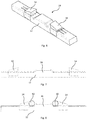
- the present invention is related to a vessel 60 as shown in figure 1 , such as a crew transfer vessel discussed previously, equipped with a bow fender 10. At least an upper part of the bow 62 is on the front face flat and is equipped with an elongated bow fender 10 placed transverse on the bow 62, as seen in figure 2 .
- a wind turbine foundation 52 is shown in figure 3 having two vertical poles/fender bars 50 to protect the turbine while the service vessel approach the turbine and allows the service personnel to use the turbine ladder 54 between the two poles for embarking and disembarking.
- the vessel's transverse bow fender 10 is pushed against the poles 50.
- a vessel 60 with a bow fender 10 according to the invention can be used to adjust or reduce the impact on the poles, or other foundation, when the vessel 60 approaches and docs at the wind turbine.
- bow fender 10 can in its simplest form be a rubber fender mounted to a base plate.
- the bow fender 10 can be in a parked position on a front face of the bow 62 of the vessel 60. In the parked position, the bow fender 10 is placed on the bow 62, i.e. adjacent or parallel to the front face of the bow 62.
- the bow fender 10 is tiltable about a pivot point or axis 46, said pivot point being for instance one or more hinges.
- the pivot point/hinges 46 is/are provided on a lower part of a backside or backplate 10a of the bow fender 10, and runs in longitudinal direction, i.e. on the transverse and flat front face of the bow 62.
- the bow fender 10 is mounted out of the water, i.e. on the upper and most forward part of the bow 62.
- the bow fender 10 can be shifted to an active position on the bow 62 of the vessel 60.
- the bow fender 10 In the active position, the bow fender 10 is pivoted or tilted to an oblique position.
- One or more actuators 42 can be used to drive the bow fender 10 from the parked position to the active position, and back again.
- the actuator(s) 42 can, as shown, be mounted between the bow 62 of the vessel 60 and an upper connection part 48 on the backside or backplate 10a of the bow fender.
- the actuators 42 may further be housed in a cavity 44, said cavity being below deck and in the front face of the bow 62.
- Several actuators 42 can be mounted in parallel, as shown in figure 2 .
- the actuators 42 are hydraulic cylinders. However, other actuators may be used, such as pneumatic cylinders or electric driven actuators.
- the actuators 42 will also act as shock dampers when a force is acting on the bow fender.
- the bow fender 10 is driven out (tilted) to the active position, for instance to an angle of 20-25°, as seen in figure 5 .
- the upper part of the bow fender 10 will then hit the poles 50 of the wind turbine foundation 52. If the vessel is 150-175 dwt and the vessel is moving at 1-2 knots, the force will be quite large.
- the forces acting on one of the support poles on the wind turbine foundation 52 may vary from 440 kN for a vessel of 150 dwt and speed of 1 knots up to 2330 kN for a vessel of 175 dwt and speed of 2 knots.
- Dependent of the angle of the bow fender and the speed of the vessel, the combined impact forces on the support points may thus vary from approximately 40 kN to 260 kN.
- the actuators 42 should, when acting as shock dampers, be able to absorb such forces.
- the actuators 42 of the bow fender 10 are preferable connected to a control system on the vessel's bridge, in order to activate the bow fender.
- one example of the bow fender 10 can comprise an elongated rubber fender 12. In the middle of the rubber fender 12 there is a ticker part 36 on the front side 12a, which is pressed against the ladder 54 of the wind turbine foundation 52.
- the bow fender 10 is as mentioned mounted on the bow of a vessel 60, such as a crew transfer vessel, with the ticker part 36 facing forward.
- the elongated fender 12 is disclosed as made of rubber, but the elongated fender 12 can be made of plastic or other suitable material.
- the bow fender 10 is disclosed in relation to a wind turbine foundation, but may of course be used with any similar offshore construction.
- Such a bow fender 10 can for instance be approximately 10m long, and with a thickness of 45cm and a height of 65-100cm.
- Support poles 50, or fender bars, on a typical wind turbine foundation 52 have a diameter of 33cm, and a center distance of for instance 1,8m.
- the ticker part 36 of the bow fender can be accommodated between the support poles 50 when the vessel 60 is pushing forward.
- the thrust by the vessel may for instance be between 8 to 10 tons.
- the bow fender 10 can be equipped with two support blocks 14, or fender clamps/shoes, which can be pushed against the outside of each support pole 50.
- the support blocks 14 are preferable used when the bow fender 10 is in the parked position.
- the support blocks 14 can each be pushed against the poles 50 with a force of for instance 5 tons, which together with the forward trust from the vessel makes the bow of the vessel steady with respect to the ladder 54, and allowing the service crew to enter the construction safely. Due to the high forces, the bow fender can for instance be compressed approximately 10cm in the area where the bow fender meets the poles. If the fender 12 is made of thick rubber, such a compression is unproblematic.
- the support blocks 14 or fender clamps/shoes are made of a baseplate 20, which at least partly envelopes the rubber fender 12.
- a rubber fender 12 normally has a square or rectangular cross-section, and the baseplate 20 is thus formed in a corresponding U-shape.
- the baseplate may have a similar shape.
- An interior width between respective side faces 20a,20b of the baseplate 20 corresponds preferable to the height of the rubber fender 12.
- the support blocks 14 are thus skidable in longitudinal directions back and forth on the front side 12a of the rubber fender 12.
- the side faces 20a,20b will normally not completely cover the rubber fender 12 to allow for compression of the rubber fender 12.
- the support blocks 14 comprises a rubber covering 30, which is placed externally on an outer side 20c of the base plate 20.
- the baseplate 20 can have a height of 65-100cm, similar to the height of the rubber fender 12, and a length of 80cm.
- the base part of the rubber covering 30 can have similar length of 80cm and a thickness of 20cm.
- the rubber covering 30 may extend quite a bit passed the baseplate 20, in the direction towards the middle of the rubber fender 12.
- the rubber covering 30 may extend passed the baseplate 20 with 20cm.
- the front face 30a of the rubber covering 30, i.e. the part that is pressed against the support poles 50 on the wind turbine foundation 54, can have an arched surface similar to the radius of the poles.
- the front part can also be thicker than the rear part.
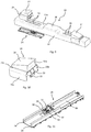
- the base plate 20 comprise on the inside one or two downward directed internal connections arm 22, which extend through longitudinal slits 16 in the front side 12a of the rubber fender 12.
- An open box with a hydraulic actuator 18, such as a hydraulic cylinder, is placed in a cavity 40 in the backside 12b of the rubber fender 12.
- the box is secured to the rubber fender 12, and can be secured to the vessel's bow.
- the connection arms 22 extending down through the slits 16 are connected to the hydraulic actuator 18 via a skid plate 26 placed in the bottom of the box.
- the skid plate 26 has a connection 34 for connection of a rod part of the actuator 18, and a connection 32 for connection of each of the connection arms 22.
- the box 24 may comprise respective side slots 28.
- the sides of the skid plate 26 may comprise a glider 38 to ease movement in the side slots 28.
- Said glider 38 can be made of brass, and the side slots 28 can be covered by a nonstick material, such as Teflon.
- the box 24 can be equipped with hinges and connected in the pivot point 46.
- the bow fender 10 is preferable connected to a control system on the vessel's bridge, in order to activate the bow fender to retract or extract the support blocks 14.
- the support blocks 14 are normally activated when the bow fender 10 is in parked position, but they may be activated also when the bow fender 10 is tilted in active position.
- Figure 4 shows the bow fender 10 without the support blocks 14, while figure 5 shows the bow fender 10 with the support block 14.
Landscapes
- Chemical & Material Sciences (AREA)
- Engineering & Computer Science (AREA)
- Combustion & Propulsion (AREA)
- Mechanical Engineering (AREA)
- Ocean & Marine Engineering (AREA)
- Body Structure For Vehicles (AREA)
Priority Applications (1)
| Application Number | Priority Date | Filing Date | Title |
|---|---|---|---|
| EP19164885.6A EP3715239A1 (fr) | 2019-03-25 | 2019-03-25 | Récipient doté d'une protection inclinable |
Applications Claiming Priority (1)
| Application Number | Priority Date | Filing Date | Title |
|---|---|---|---|
| EP19164885.6A EP3715239A1 (fr) | 2019-03-25 | 2019-03-25 | Récipient doté d'une protection inclinable |
Publications (1)
| Publication Number | Publication Date |
|---|---|
| EP3715239A1 true EP3715239A1 (fr) | 2020-09-30 |
Family
ID=65911077
Family Applications (1)
| Application Number | Title | Priority Date | Filing Date |
|---|---|---|---|
| EP19164885.6A Withdrawn EP3715239A1 (fr) | 2019-03-25 | 2019-03-25 | Récipient doté d'une protection inclinable |
Country Status (1)
| Country | Link |
|---|---|
| EP (1) | EP3715239A1 (fr) |
Cited By (2)
| Publication number | Priority date | Publication date | Assignee | Title |
|---|---|---|---|---|
| CN116620498A (zh) * | 2023-03-10 | 2023-08-22 | 福建海电运维科技股份有限公司 | 一种风电运维船顶靠橡胶碰垫 |
| US12337947B2 (en) * | 2022-12-19 | 2025-06-24 | Hyundai Motor Company | Dispersion structure for impact |
Citations (10)
| Publication number | Priority date | Publication date | Assignee | Title |
|---|---|---|---|---|
| US445910A (en) | 1891-02-03 | Elastic fender for vessels | ||
| FR2314861A1 (fr) | 1975-06-17 | 1977-01-14 | Brummenaes Irving | Procede d'accostage d'un bateau a un debarcadere et ensemble de dispositifs pare-chocs |
| JPS5483293A (en) | 1977-12-13 | 1979-07-03 | Bridgestone Corp | Fender device |
| SU1105386A1 (ru) | 1983-04-11 | 1984-07-30 | Предприятие П/Я Г-4806 | Устройство дл защиты от повреждени подводных крыльев судна при швартовке |
| US20100012009A1 (en) | 2002-07-30 | 2010-01-21 | Cavotec Msl Holdings Limited | Mooring system with active control |
| GB2475085A (en) * | 2009-11-05 | 2011-05-11 | David Armstrong | Pivoting deck vessel for allowing transfer to a fixed structure |
| GB2476858A (en) | 2010-11-19 | 2011-07-13 | Ronald Stephen Mattey | Apparatus for stabilising a floating craft against a stationary structure |
| KR20110137585A (ko) * | 2010-06-17 | 2011-12-23 | 삼성중공업 주식회사 | 펜더 장치 및 그 장치를 구비한 선박 |
| EP2520485A1 (fr) | 2011-05-03 | 2012-11-07 | Presign Holding B.V. | Système et procédé pour amarrer un vaisseau flottant contre un objet fixe |
| EP3323708A1 (fr) | 2016-11-22 | 2018-05-23 | Offshore Windservice A/S | Défense de proue |
-
2019
- 2019-03-25 EP EP19164885.6A patent/EP3715239A1/fr not_active Withdrawn
Patent Citations (10)
| Publication number | Priority date | Publication date | Assignee | Title |
|---|---|---|---|---|
| US445910A (en) | 1891-02-03 | Elastic fender for vessels | ||
| FR2314861A1 (fr) | 1975-06-17 | 1977-01-14 | Brummenaes Irving | Procede d'accostage d'un bateau a un debarcadere et ensemble de dispositifs pare-chocs |
| JPS5483293A (en) | 1977-12-13 | 1979-07-03 | Bridgestone Corp | Fender device |
| SU1105386A1 (ru) | 1983-04-11 | 1984-07-30 | Предприятие П/Я Г-4806 | Устройство дл защиты от повреждени подводных крыльев судна при швартовке |
| US20100012009A1 (en) | 2002-07-30 | 2010-01-21 | Cavotec Msl Holdings Limited | Mooring system with active control |
| GB2475085A (en) * | 2009-11-05 | 2011-05-11 | David Armstrong | Pivoting deck vessel for allowing transfer to a fixed structure |
| KR20110137585A (ko) * | 2010-06-17 | 2011-12-23 | 삼성중공업 주식회사 | 펜더 장치 및 그 장치를 구비한 선박 |
| GB2476858A (en) | 2010-11-19 | 2011-07-13 | Ronald Stephen Mattey | Apparatus for stabilising a floating craft against a stationary structure |
| EP2520485A1 (fr) | 2011-05-03 | 2012-11-07 | Presign Holding B.V. | Système et procédé pour amarrer un vaisseau flottant contre un objet fixe |
| EP3323708A1 (fr) | 2016-11-22 | 2018-05-23 | Offshore Windservice A/S | Défense de proue |
Cited By (2)
| Publication number | Priority date | Publication date | Assignee | Title |
|---|---|---|---|---|
| US12337947B2 (en) * | 2022-12-19 | 2025-06-24 | Hyundai Motor Company | Dispersion structure for impact |
| CN116620498A (zh) * | 2023-03-10 | 2023-08-22 | 福建海电运维科技股份有限公司 | 一种风电运维船顶靠橡胶碰垫 |
Similar Documents
| Publication | Publication Date | Title |
|---|---|---|
| US8925130B2 (en) | Access apparatus for transferring from vessels to fixed structures | |
| NL1009277C2 (nl) | Werkwijze en inrichting voor het nauwkeurig plaatsen van relatief zware voorwerpen op en wegnemen van zware voorwerpen van de zeebodem. | |
| EP2316721B1 (fr) | Procédé de stabilisation d'un navire contre un objet immobile | |
| EP3323708B1 (fr) | Défense de proue | |
| EP3715239A1 (fr) | Récipient doté d'une protection inclinable | |
| WO2015120862A1 (fr) | Procédé et système de compensation de gîte de bateau, et bateau pourvu dudit système | |
| US11760447B2 (en) | System for stabilizing a vessel against a stationary object | |
| EP2923941A1 (fr) | Dispositif amortisseur hydraulique maritime | |
| NZ546441A (en) | Horizontally disposed hydrofoil system for monohull sailboat | |
| CN1226865A (zh) | 集装箱船装卸装置 | |
| AU2018343213B2 (en) | Motor boat with foils which are retractable by tilting | |
| NL2008207C2 (en) | A method of providing access between a floating vessel and a marine structure. | |
| US8181588B2 (en) | Automatic reversing-reposition rocker arm | |
| GB2024734A (en) | A cargo loading and unloading assembly for ships | |
| CN109533217B (zh) | 可变平衡翼海上作业船 | |
| CN114435537B (zh) | 用以抛石作业的船舶定位装置 | |
| FR3016341A1 (fr) | Dispositif de mat telescopique de navire | |
| NO345559B1 (no) | System for offshore kraftgenerering | |
| CN117302432A (zh) | 一种海用监测平台回收方法及装置 | |
| CN214029058U (zh) | 一种工作艇滑道收放装置 | |
| NL1043284B9 (nl) | Ontwikkelingen en verbeteringen van "Automatische losinrichting bij het wegvaren" naar ook automatisch aanleggen | |
| EP3318477A1 (fr) | Voilier à faible gîte | |
| NL2014304B1 (en) | Tugboat provided with a carrousel-type towing system. | |
| CN221214455U (zh) | 一种可拆卸船艇尾板 | |
| CN214363302U (zh) | 一种可高度调节的系船柱 |
Legal Events
| Date | Code | Title | Description |
|---|---|---|---|
| PUAI | Public reference made under article 153(3) epc to a published international application that has entered the european phase |
Free format text: ORIGINAL CODE: 0009012 |
|
| STAA | Information on the status of an ep patent application or granted ep patent |
Free format text: STATUS: THE APPLICATION HAS BEEN PUBLISHED |
|
| AK | Designated contracting states |
Kind code of ref document: A1 Designated state(s): AL AT BE BG CH CY CZ DE DK EE ES FI FR GB GR HR HU IE IS IT LI LT LU LV MC MK MT NL NO PL PT RO RS SE SI SK SM TR |
|
| AX | Request for extension of the european patent |
Extension state: BA ME |
|
| STAA | Information on the status of an ep patent application or granted ep patent |
Free format text: STATUS: THE APPLICATION IS DEEMED TO BE WITHDRAWN |
|
| 18D | Application deemed to be withdrawn |
Effective date: 20210331 |