EP3323737B1 - Machine à ficeler une barre d'armature - Google Patents
Machine à ficeler une barre d'armature Download PDFInfo
- Publication number
- EP3323737B1 EP3323737B1 EP17192273.5A EP17192273A EP3323737B1 EP 3323737 B1 EP3323737 B1 EP 3323737B1 EP 17192273 A EP17192273 A EP 17192273A EP 3323737 B1 EP3323737 B1 EP 3323737B1
- Authority
- EP
- European Patent Office
- Prior art keywords
- wire
- tying machine
- steel wire
- main body
- rebar tying
- Prior art date
- Legal status (The legal status is an assumption and is not a legal conclusion. Google has not performed a legal analysis and makes no representation as to the accuracy of the status listed.)
- Active
Links
- 238000004804 winding Methods 0.000 claims description 42
- 229910000831 Steel Inorganic materials 0.000 claims description 37
- 239000010959 steel Substances 0.000 claims description 37
- 238000007599 discharging Methods 0.000 claims description 20
- 230000005540 biological transmission Effects 0.000 claims description 16
- 238000005520 cutting process Methods 0.000 claims description 9
- NJPPVKZQTLUDBO-UHFFFAOYSA-N novaluron Chemical compound C1=C(Cl)C(OC(F)(F)C(OC(F)(F)F)F)=CC=C1NC(=O)NC(=O)C1=C(F)C=CC=C1F NJPPVKZQTLUDBO-UHFFFAOYSA-N 0.000 claims description 6
- 230000003014 reinforcing effect Effects 0.000 claims description 2
- 238000010586 diagram Methods 0.000 description 18
- 230000033001 locomotion Effects 0.000 description 4
- 230000002093 peripheral effect Effects 0.000 description 4
- 230000007704 transition Effects 0.000 description 3
- 238000000034 method Methods 0.000 description 2
- 230000002452 interceptive effect Effects 0.000 description 1
- 238000004519 manufacturing process Methods 0.000 description 1
- 230000002035 prolonged effect Effects 0.000 description 1
- 238000004904 shortening Methods 0.000 description 1
- 239000007858 starting material Substances 0.000 description 1
Images








Classifications
-
- E—FIXED CONSTRUCTIONS
- E04—BUILDING
- E04G—SCAFFOLDING; FORMS; SHUTTERING; BUILDING IMPLEMENTS OR AIDS, OR THEIR USE; HANDLING BUILDING MATERIALS ON THE SITE; REPAIRING, BREAKING-UP OR OTHER WORK ON EXISTING BUILDINGS
- E04G21/00—Preparing, conveying, or working-up building materials or building elements in situ; Other devices or measures for constructional work
- E04G21/12—Mounting of reinforcing inserts; Prestressing
- E04G21/122—Machines for joining reinforcing bars
- E04G21/123—Wire twisting tools
-
- B—PERFORMING OPERATIONS; TRANSPORTING
- B65—CONVEYING; PACKING; STORING; HANDLING THIN OR FILAMENTARY MATERIAL
- B65B—MACHINES, APPARATUS OR DEVICES FOR, OR METHODS OF, PACKAGING ARTICLES OR MATERIALS; UNPACKING
- B65B13/00—Bundling articles
- B65B13/02—Applying and securing binding material around articles or groups of articles, e.g. using strings, wires, strips, bands or tapes
- B65B13/04—Applying and securing binding material around articles or groups of articles, e.g. using strings, wires, strips, bands or tapes with means for guiding the binding material around the articles prior to severing from supply
-
- B—PERFORMING OPERATIONS; TRANSPORTING
- B65—CONVEYING; PACKING; STORING; HANDLING THIN OR FILAMENTARY MATERIAL
- B65B—MACHINES, APPARATUS OR DEVICES FOR, OR METHODS OF, PACKAGING ARTICLES OR MATERIALS; UNPACKING
- B65B13/00—Bundling articles
- B65B13/02—Applying and securing binding material around articles or groups of articles, e.g. using strings, wires, strips, bands or tapes
- B65B13/04—Applying and securing binding material around articles or groups of articles, e.g. using strings, wires, strips, bands or tapes with means for guiding the binding material around the articles prior to severing from supply
- B65B13/06—Stationary ducts or channels
-
- B—PERFORMING OPERATIONS; TRANSPORTING
- B65—CONVEYING; PACKING; STORING; HANDLING THIN OR FILAMENTARY MATERIAL
- B65B—MACHINES, APPARATUS OR DEVICES FOR, OR METHODS OF, PACKAGING ARTICLES OR MATERIALS; UNPACKING
- B65B13/00—Bundling articles
- B65B13/18—Details of, or auxiliary devices used in, bundling machines or bundling tools
- B65B13/185—Details of tools
- B65B13/187—Motor means
-
- B—PERFORMING OPERATIONS; TRANSPORTING
- B65—CONVEYING; PACKING; STORING; HANDLING THIN OR FILAMENTARY MATERIAL
- B65B—MACHINES, APPARATUS OR DEVICES FOR, OR METHODS OF, PACKAGING ARTICLES OR MATERIALS; UNPACKING
- B65B13/00—Bundling articles
- B65B13/18—Details of, or auxiliary devices used in, bundling machines or bundling tools
- B65B13/24—Securing ends of binding material
- B65B13/28—Securing ends of binding material by twisting
- B65B13/285—Hand tools
-
- B—PERFORMING OPERATIONS; TRANSPORTING
- B65—CONVEYING; PACKING; STORING; HANDLING THIN OR FILAMENTARY MATERIAL
- B65B—MACHINES, APPARATUS OR DEVICES FOR, OR METHODS OF, PACKAGING ARTICLES OR MATERIALS; UNPACKING
- B65B13/00—Bundling articles
- B65B13/02—Applying and securing binding material around articles or groups of articles, e.g. using strings, wires, strips, bands or tapes
- B65B13/025—Hand-held tools
-
- B—PERFORMING OPERATIONS; TRANSPORTING
- B65—CONVEYING; PACKING; STORING; HANDLING THIN OR FILAMENTARY MATERIAL
- B65B—MACHINES, APPARATUS OR DEVICES FOR, OR METHODS OF, PACKAGING ARTICLES OR MATERIALS; UNPACKING
- B65B13/00—Bundling articles
- B65B13/18—Details of, or auxiliary devices used in, bundling machines or bundling tools
- B65B13/185—Details of tools
-
- B—PERFORMING OPERATIONS; TRANSPORTING
- B65—CONVEYING; PACKING; STORING; HANDLING THIN OR FILAMENTARY MATERIAL
- B65B—MACHINES, APPARATUS OR DEVICES FOR, OR METHODS OF, PACKAGING ARTICLES OR MATERIALS; UNPACKING
- B65B27/00—Bundling particular articles presenting special problems using string, wire, or narrow tape or band; Baling fibrous material, e.g. peat, not otherwise provided for
- B65B27/10—Bundling rods, sticks, or like elongated objects
Definitions
- the present invention relates to a rebar tying machine according to claim 1.
- a rebar tying machine includes: a tying thread feeding mechanism, configured to feed a tying thread for a steel wire reeled on a steel wire reel and wind the tying thread on the rebar; and a tying thread twisting mechanism, configured to twist the tying thread wound on the rebar.
- the tying thread feeding mechanism and the tying thread twisting mechanism work in sequence through the operation of a starter, in order to complete a series of tying actions.
- a rebar tying machine including: a main sleeve having a hook pivotally mounted at its leading end, a leading end shaft nested inside the main sleeve, a spiral threaded groove formed at the leading end shaft, a nested opening passing through the main sleeve from outside to inside, a tab which is nested in the nested opening and clamped into the threaded groove, a short sleeve which is disposed on the periphery of the main sleeve and covers the tab, and a clamping unit which is formed on the short sleeve and controls the rotation of the main sleeve.
- the rebar tying machine with such a structure has relatively low stability during operation and is easily jammed after dirt enters the mechanism.
- a rebar tying machine of the kind defined by the preamble of claim 1 is known from the JP 2003 041777 A .
- the rebar tying machine of WO 2007/141822 A1 discloses a steel wire cutting-off mechanism comprising a transmission device, a wire discharging block and a linear cutting-off device, which are mounted within the main body.
- the transmission device is connected to the linear cutting-off device.
- the wire discharging block has a wire discharging passage, and is further provided with a chute intersected with the wire discharging passage.
- a wire cutter is provided in the linear cutting-off device linearly slides in the chute.
- the technical problem to be solved by the present invention is to provide a rebar tying machine which has accurate positioning, high safety factor and long service life and can effectively avoid the generation of jamming, in order to overcome shortcomings of the prior art.
- the invention provides for a rebar tying machine with the features of claim 1.
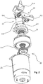
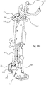
- a rebar tying machine including a tying machine main body 1 and a steel wire winding assembly 2 mounted within the tying machine main body 1.
- the steel wire winding assembly 2 includes a winding mechanism 21 and a driving device 22 for driving the winding mechanism 21, and a locking device 23 for locking the winding mechanism 21.
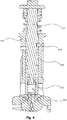
- An anti-rotation fixing pin 231 of the locking device 23 axially moves in the advance/retreat locating slot 211, and slides in a peripheral direction in the rotating cam slot 212.
- the winding mechanism 21 internally starts to rotate under the drive of the driving device 22.
- the anti-rotation fixing pin 231 in the locking device 23 is located in the advance/retreat locating slot 211, and the winding mechanism 21 can just advance or retreat instead of rotating; and after the winding mechanism 21 is advanced for a certain distance, the anti-rotation fixing pin 231 will slip out from the winding mechanism 21 into the rotating cam slot 212, and can slide in a peripheral direction in the rotating cam slot 212, and at this moment the winding mechanism 21 may rotate.
- the positioning of the steel wire winding assembly 2 is much more accurate, and the safety factor of the overall work is improved by the advance/retreat locating slot 211 and the rotating cam slot 212.
- two advance/retreat locating slots 211 and two rotating cam slots 212 are disposed symmetrically, thereby substantially ensuring that the anti-rotation fixing pin 231 can enter the locating slot when the winding mechanism 21 rotates for half cycle at most and that the sleeve carries out a linear retreat movement, saving the return time, shortening the duration of one working cycle and improving the operating efficiency.
- the advance/retreat locating slot 211 is axially disposed along the winding mechanism 21, and the rotating cam slot 212 is peripherally disposed along the winding mechanism 21.
- Such a structure ensures that the anti-rotation fixing pin 231 in the locking device 23 can accurately move in the axial direction and the peripheral direction of the winding mechanism 21, and that the winding mechanism 21 operates stably and accurately.
- the rotating cam slot 212 is gradually shallower in the peripheral direction, and the axial extension of a side wall of the rotating cam slot 212 along a sleeve 216 forms a chamfer structure by which the anti-rotation fixing pin 231 is prevented from being jammed in the rotating cam slot 212 when the driving device 22 rotates reversely and the sleeve 216 retreats.
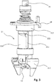
- the winding mechanism 21 includes an inner core 213, a winding guide head 214 mounted on the inner core 213, and a lead screw 215 driving the inner core 213.
- the inner core 213 and the lead screw 215 are mounted within the sleeve 216, and the advance/retreat locating slot 211 and the rotating cam slot 212 are disposed on the sleeve 216.
- a fixing sheath 217 is mounted on the sleeve 216.
- a threaded block 218 connected to the sleeve 216 through the fixing sheath 217 is mounted on the lead screw 215.
- the driving device 22 drives the lead screw 215 to rotate, and the lead screw 215 drives the inner core 213 to open the winding guide head 214 during the rotation.
- the threaded block 218, which is fitted with the spiral structure on the lead screw 215 is mounted on the sleeve 216 sleeved outside the lead screw 215.
- the anti-rotation fixing pin 231 is located in the advance/retreat locating slot 211 on the sleeve 215, and can just take linear advance movement under the action of the lead screw 215 and the threaded block 218.
- the winding guide head 214 moves to the location of the steel wires and clamps them when the sleeve 216 advances.
- the anti-rotation fixing pin 231 on the locking device 23 moves relative to the sleeve 216 back to a position where the rotating cam slot 212 is located.
- the anti-rotation fixing pin 231 is unable to restrict the rotation of the sleeve 216, and this moment the threaded block also moves to a top end of the spiral structure on the lead screw.
- the lead screw is connected to the sleeve and the winding guide head 214 through the threaded block to rotate together, in order to twist the clamped steel wires, thereby for winding.
- the driving device 22 starts to drive the lead screw 215 to rotate reversely, and the sleeve 216 retreats and rotates reversely accordingly. Due to the single direction of the rotating cam slot 212, the anti-rotation fixing pin 231 is clamped into the groove, and the rotation of the sleeve 216 is restricted only to linear retreat movement under the action of the lead screw 215. The anti-rotation fixing pin 231 enters the advance/retreat locating slot 211, the driving device 22 stops operating, and the winding mechanism 21 is fixed in a correct standby position. The process thus enters the next operating state.
- the winding mechanism 21 further includes a wire cutting plate 24 mounted on the sleeve 216 through the fixing sheath 217.
- the wire cutting plate 24 in the winding mechanism 21 is connected to a linear cutting-off device 33, and the wire cutting plate 24 is connected to the linear cutting-off device 33 on the tying machine main body 1.
- the wire cutting plate 24 travels forward to enable the linear cutting-off device 33 to cut the steel wire off.
- the driving device 22 includes a drive motor 221 and a transmission gear set 222 connected to the drive motor 221, the transmission gear set 222 being connected to the lead screw 215.
- the drive motor 221 in the driving device 22 powers the lead screw 215 to rotate and rotate reversely, and the power output by the drive motor 221 is transferred to the lead screw 215 by the transmission gear set 222 connected to the lead screw 215.
- the transmission gear set 222 uses a transmission mode of a planetary gear set. However, it is not limited thereto, and other transmission modes may be used.
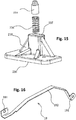
- the locking device 23 further includes a fixing base 232 and a connecting plate 233 mounted on the fixing base 232.
- the anti-rotation fixing pin 231 is mounted on the connecting plate 233, and a fixing shaft 235 with a resetting spring 234 is disposed on the fixing base 232; and the connecting plate 233 is mounted on the fixing shaft 234. Since the advance/retreat locating slot 211 and the rotating cam slot 212, which are disposed on an outer wall of the sleeve 216, are fitted with the resetting spring 234 on the fixing shaft 235, the jamming caused by the entrance of the dirt is effectively avoided, and the service life of the machine is prolonged.
- the locking device 23 further includes a pedestal 236 having thereon a hollow protrusion 237 within which the anti-rotation fixing pin 231 is disposed.
- a resetting spring 234 is provided between the anti-rotation fixing pin 231 and the protrusion 237; and a reinforcing rib 238 is formed between the pedestal 236 and the protrusion 237 to reinforce the connection strength. Since the advance/retreat locating slot 211 and the rotating cam slot 212 are fitted with each other by the anti-rotation fixing pin therein, when in operation, the winding assembly can automatically rotate and stop rotating in accordance with specific conditions, thereby improving the safety factor of the overall operation.
- the steel wire cutting-off mechanism 3 includes a transmission device 31, a wire discharging block 32 and a linear cutting-off device 33.
- the transmission device 31 is connected to the linear cutting-off device 33;
- the wire discharging block 32 has a wire discharging passage 321, and is further provided with a chute 322 intersected with the wire discharging passage 321; and a wire cutter 323 in the linear cutting-off device 33 linearly slides in the chute 322.
- the chute 322 intersected with the wire discharging passage 321 is disposed within the wire discharging block 32.
- the rebar tying machine lowers the processing requirements and is easy to mount and low in production cost.
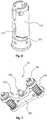
- the linear cutting-off device 33 includes an oscillator 331 connected to the wire cutter 323, a driving leg 332 of the oscillator 331 is connected to the transmission device 31, and a linkage leg 333 of the oscillator 331 is connected to the wire cutter 323 through a connecting sheet 334.
- the transmission device 31 includes a large fork 312 and a small fork 313 connected to each other through a connecting pin 311, and a lower drive plate 314 connected to the large fork 312.
- the small fork 313 is connected to the oscillator 331 through a connecting rod 315.
- a guide portion 11, the leading end of which bends into a circular arc, is disposed at the leading end of the main body 1, the oscillator 331 is rotationally mounted on the guide portion 11 through a bushing 12, and the wire discharging block 32 is mounted at the leading end of the guide portion 11.
- a waist-shaped hole 13 is formed on the guide portion 11, and the driving leg 333 can slide in the waist-shaped hole 13 to be connected to the connecting rod 315.
- a wire guide block 14 is disposed on the guide portion 11, and a wire guide post 15 by which the steel wires are led into the wire discharging block 32 is disposed on the wire guide block 14.
- the large fork 312 and the small fork 313 are rotationally mounted on the guide portion 11, with triggers 16 being disposed on the large fork 312 and the small fork 313 and supported against the wire cutting plate 24.
- an elastic wire guide piece 18 is mounted in the wire discharging passage 321 of the guide portion 11, both two ends of the elastic wire guide piece 18 are bent to form a fixing piece 181 by which the elastic wire guide piece 18 is mounted on the guide portion 11, and a downward-bent leading portion 182 fitted with the wire discharging passage 321 is formed on the elastic wire guide piece 18.
- a steel wire reel 4 and a wire wheel brake mechanism 5 for restricting the rotation of the steel wire reel 4 can be rotationally mounted on the main body 1.
- a power transmission device 6 for driving the wire wheel brake mechanism 5 is mounted on the guide portion 11, and connected to the wire cutting plate 24; the power transmission device 6 includes a brake plate 61 and a linkage plate 63 connected to the brake plate 61 through a lower connecting rod 62, the linkage plate 63 being connected to the wire wheel brake mechanism 5, the brake plate 61 being resisted against the wire cutting plate24.
- the wire wheel brake mechanism 5 includes a brake shaft 51, as well as a brake piece 52 and a brake rocker arm 53 which are both rotationally mounted on the brake shaft 51, the brake piece 52 being connected to the steel wire reel 4.
- Locking grooves 41 are evenly disposed on the steel wire reel 4; and a bent brake block 54 is formed on the brake piece 52 and clamped within the locking grooves 41.
- an accommodating cavity 42 for accommodating the steel wire reel 4 is disposed on the main body 1; and a cover plate 43 is rotationally mounted at the accommodating cavity 42 on the main body 1.
- a rotating lock device 44 is mounted on the cover plate 43, and the steel wire reel 4 is mounted within the accommodating cavity 42 by the cover plate 43 through the rotating lock device 44. Since the rotating lock device 44 is mounted on the tying machine main body 1, not only the steel wire reel 4 may be mounted on the main body 1, but also the cover plate 43 mounted on the tying machine main body 1 may be completely opened, without interfering the mounting and demounting of the steel wire reel 4 so that the steel wire reel 4 may be demounted and mounted conveniently.
- the rotating lock device 44 includes a cover plate chuck 441 mounted on the main body 1, and a rotary knob 442 rotationally mounted on the cover plate 43, the rotary knob 442 being clamped on the cover plate chuck 441.
- the cover plate 43 is forced in a closed direction, and when the rotary knob 442 mounted on the cover plate 43 is turned to have a click sound, it is indicated that the rotary knob 442 has been clamped into the cover plate chuck 441. Therefore, the cover plate 43 has been in a locked state.
- a user may close the cover plate 43 without turning the rotary knob 442, so that some action may be omitted during the operation.
- the rotary knob 442 may rotate around a rotary knob securing shaft 448 for rotationally mounting the rotary knob 442.
- the cover plate 43 is automatically opened under the action of a cover plate torsion spring on a hinge shaft between the cover plate 43 and the main body 1.
- a clamping slot 443 is formed on the cover plate chuck 441.
- a clamp leg 444 and a push bar 445 are disposed on the rotary knob 442.
- the steel wire reel 4 is mounted within the accommodating cavity 42 by clamping the clamp leg 444 into the clamping slot 443; and a transition bevel 446 is formed at the leading end of the cover plate chuck 441.
- the clamp leg 444 is clamped into the clamping slot 443 through the transition bevel 446, and the push bar 445 is connected to the clamp leg 444 through a connecting block 447.
- the rotary knob 442 is automatically clamped into the clamping slot 443 under the action of the torsion spring, thereby locking the cover plate 43.
Landscapes
- Engineering & Computer Science (AREA)
- Mechanical Engineering (AREA)
- Architecture (AREA)
- Civil Engineering (AREA)
- Structural Engineering (AREA)
- Basic Packing Technique (AREA)
Claims (1)
- Machine à ficeler une barre d'armature comprenant un corps principal de machine à ficeler (1) et un ensemble d'enroulement de fil d'acier (2) monté dans le corps principal (1),
dans laquelle l'ensemble d'enroulement de fil d'acier (2) comprend un mécanisme d'enroulement (21) et un dispositif d'entraînement (22) pour l'entraînement du mécanisme d'enroulement (21), et comprend en outre un dispositif de verrouillage (23) ; une fente de positionnement d'avance/de recul (211) disposée axialement le long du mécanisme d'enroulement (21) et une fente de came rotative (212) disposée le long de la périphérie du mécanisme d'enroulement (21) qui sont en communication l'une avec l'autre et sont disposées sur le mécanisme d'enroulement (21) ; un axe de fixation antirotation (231) du dispositif de verrouillage (23) se déplaçant dans la fente de positionnement d'avance/de recul (211), et coulissant dans la fente de came rotative (212) ; et un mécanisme de découpe de fil d'acier (3), auquel une plaque de coupe de fil (24) dans l'ensemble d'enroulement de fil d'acier (2) est raccordée, est en outre monté dans le corps principal (1) ;
caractérisée en ce que
le mécanisme de découpe de fil d'acier (3) comprend un dispositif de transmission (31), un bloc d'évacuation de fil (32) et un dispositif de découpe linéaire (33) qui sont montés dans le corps principal (1) ; le dispositif de transmission (31) est raccordé au dispositif de découpe linéaire (33) ;
le bloc d'évacuation de fil (32) présente un passage d'évacuation de fil (321), et est en outre doté d'une glissière (322) en intersection avec le passage d'évacuation de fil (321) ;
dans laquelle
un dispositif de coupe de fil (323) dans le dispositif de découpe linéaire (33) coulisse linéairement dans la glissière (322), le dispositif de verrouillage (23) comprend en outre un socle (236) fixé sur le corps principal (1) et présentant dessus une saillie creuse (237) dans laquelle l'axe de fixation antirotation (231) est disposé ;
un ressort de réinitialisation (234) est prévu entre l'axe de fixation antirotation (231) et la saillie (237) ; et
une nervure de renforcement (238) est formée entre le socle (236) et la saillie (237).
Applications Claiming Priority (3)
| Application Number | Priority Date | Filing Date | Title |
|---|---|---|---|
| CN2013202914709U CN203237416U (zh) | 2013-05-23 | 2013-05-23 | 钢丝绕丝总成以及钢筋捆扎机 |
| PCT/CN2013/001410 WO2014186927A1 (fr) | 2013-05-23 | 2013-11-18 | Machine à ficeler une barre d'armature |
| EP13885145.6A EP3000738B1 (fr) | 2013-05-23 | 2013-11-18 | Machine à ficeler une barre d'armature |
Related Parent Applications (2)
| Application Number | Title | Priority Date | Filing Date |
|---|---|---|---|
| EP13885145.6A Division EP3000738B1 (fr) | 2013-05-23 | 2013-11-18 | Machine à ficeler une barre d'armature |
| EP13885145.6A Division-Into EP3000738B1 (fr) | 2013-05-23 | 2013-11-18 | Machine à ficeler une barre d'armature |
Publications (2)
| Publication Number | Publication Date |
|---|---|
| EP3323737A1 EP3323737A1 (fr) | 2018-05-23 |
| EP3323737B1 true EP3323737B1 (fr) | 2019-09-18 |
Family
ID=49314739
Family Applications (2)
| Application Number | Title | Priority Date | Filing Date |
|---|---|---|---|
| EP17192273.5A Active EP3323737B1 (fr) | 2013-05-23 | 2013-11-18 | Machine à ficeler une barre d'armature |
| EP13885145.6A Active EP3000738B1 (fr) | 2013-05-23 | 2013-11-18 | Machine à ficeler une barre d'armature |
Family Applications After (1)
| Application Number | Title | Priority Date | Filing Date |
|---|---|---|---|
| EP13885145.6A Active EP3000738B1 (fr) | 2013-05-23 | 2013-11-18 | Machine à ficeler une barre d'armature |
Country Status (4)
| Country | Link |
|---|---|
| US (1) | US10443252B2 (fr) |
| EP (2) | EP3323737B1 (fr) |
| CN (1) | CN203237416U (fr) |
| WO (1) | WO2014186927A1 (fr) |
Families Citing this family (37)
| Publication number | Priority date | Publication date | Assignee | Title |
|---|---|---|---|---|
| CN203237416U (zh) * | 2013-05-23 | 2013-10-16 | 台州市新大陆电子科技有限公司 | 钢丝绕丝总成以及钢筋捆扎机 |
| KR101518227B1 (ko) * | 2014-05-15 | 2015-05-12 | 김병수 | 배근 결속장치 |
| CN104533095B (zh) * | 2014-12-17 | 2016-10-05 | 广东顺德华焱电子科技有限公司 | 一种自动钢筋捆扎机 |
| CN116988655A (zh) | 2015-07-22 | 2023-11-03 | 美克司株式会社 | 捆扎机 |
| JP6674265B2 (ja) * | 2016-01-28 | 2020-04-01 | 株式会社マキタ | 鉄筋結束機 |
| JP6698425B2 (ja) | 2016-05-20 | 2020-05-27 | 株式会社マキタ | 鉄筋結束機 |
| JP6919017B2 (ja) * | 2016-05-20 | 2021-08-11 | 株式会社マキタ | 鉄筋結束機 |
| JP6930097B2 (ja) * | 2016-12-07 | 2021-09-01 | マックス株式会社 | 結束機 |
| CN106639332B (zh) * | 2017-01-24 | 2022-08-30 | 应海萍 | 一种钢筋捆扎机 |
| CN107165416A (zh) * | 2017-05-23 | 2017-09-15 | 成都智诚利合科技有限公司 | 一种建筑物混凝土的预埋钢筋智能捆扎设备 |
| GB201710375D0 (en) * | 2017-06-28 | 2017-08-09 | Sympafix Bv | Wire reels for reinforcing bar binding machinery |
| WO2019227304A1 (fr) * | 2018-05-29 | 2019-12-05 | 广东顺德华焱电子科技有限公司 | Mécanisme de liaison pour machine d'attache de barre d'armature et machine d'attache de barre d'armature |
| CN108590196A (zh) * | 2018-05-29 | 2018-09-28 | 广东顺德华焱电子科技有限公司 | 一种钢筋捆扎机的联动机构及钢筋捆扎机 |
| CN108560925B (zh) * | 2018-06-07 | 2023-08-29 | 建科机械(天津)股份有限公司 | 一种钢筋绑扎机 |
| JP7175557B2 (ja) | 2018-07-06 | 2022-11-21 | 株式会社共和 | 結束機 |
| JP7259225B2 (ja) * | 2018-07-31 | 2023-04-18 | マックス株式会社 | 結束機 |
| JP6633720B1 (ja) * | 2018-11-08 | 2020-01-22 | 建ロボテック株式会社 | 鉄筋結束用自走ロボット |
| CN110700595A (zh) * | 2019-10-30 | 2020-01-17 | 理工华汇(潍坊)智能机器人有限公司 | 一种用于绑扎的扭转机构 |
| CN110980207A (zh) * | 2019-12-28 | 2020-04-10 | 深圳市智信精密仪器有限公司 | 一种回流传送夹治具快速上料并夹紧装置 |
| DK180547B1 (en) * | 2020-02-05 | 2021-06-17 | Cmc Elements Aps | Binding Structure |
| CN111550057A (zh) * | 2020-03-31 | 2020-08-18 | 新昌县七星街道新伟机械厂 | 一种建筑钢筋交接处捆扎用施工装置 |
| JP7047880B2 (ja) * | 2020-10-29 | 2022-04-05 | マックス株式会社 | 結束機 |
| CN112554571B (zh) * | 2020-11-20 | 2022-09-09 | 安徽广泱建设工程有限公司 | 一种钢筋捆扎定位组装辅助胎具 |
| CN113235938B (zh) * | 2021-04-29 | 2022-12-09 | 中建三局科创产业发展有限公司 | 一种建筑工地用钢筋捆扎机 |
| CN113844723A (zh) * | 2021-09-18 | 2021-12-28 | 台州市新大陆电子科技有限公司 | 一种可反馈工作状态的捆扎机及其方法 |
| CN114086769B (zh) * | 2021-11-16 | 2022-11-22 | 北京好运达智创科技有限公司 | 一种位置可调的钢筋绑扎装置 |
| CN113982278B (zh) * | 2021-11-29 | 2023-10-10 | 新晟建设集团有限公司 | 一种建筑钢筋自动捆扎装置 |
| CN114669684A (zh) * | 2022-03-23 | 2022-06-28 | 贵州大通路桥工程建设有限公司 | 一种隧道二衬钢筋弯曲安装的机械装置 |
| CN115821747B (zh) * | 2022-07-19 | 2025-11-11 | 中交建筑集团第六工程有限公司 | 一种现浇桥梁下构系梁钢筋辅助安装设备 |
| CN115045513B (zh) * | 2022-07-20 | 2024-02-09 | 武汉建工集团股份有限公司 | 一种建筑施工钢筋快速自动绑扎装置及其使用方法 |
| CN115324358B (zh) * | 2022-08-30 | 2024-04-26 | 上海大学 | 一种钢筋绑扎机 |
| CN115788058A (zh) * | 2022-12-16 | 2023-03-14 | 台州市新大陆电子科技有限公司 | 一种由绕丝内套切丝的钢筋捆扎机 |
| CN115822269B (zh) * | 2022-12-16 | 2025-07-15 | 台州市新大陆电子科技有限公司 | 一种可顶出丝圈的钢筋捆扎机 |
| JP1768705S (ja) * | 2023-06-13 | 2024-04-22 | 鉄筋結束機 | |
| JP1766305S (ja) * | 2023-06-13 | 2024-03-25 | 鉄筋結束機本体 | |
| CN117086230A (zh) * | 2023-09-15 | 2023-11-21 | 福建三钢闽光股份有限公司 | 一种钢筋弯曲打包装置及其使用方法 |
| CN118204449B (zh) * | 2024-04-12 | 2024-08-16 | 东华链条兴化有限公司 | 一种多功能金属线材剪断设备 |
Family Cites Families (11)
| Publication number | Priority date | Publication date | Assignee | Title |
|---|---|---|---|---|
| DE69610371T2 (de) * | 1995-06-30 | 2001-01-25 | Max Co. Ltd., Tokio/Tokyo | Drahtführungsvorrichtung für eine Vorrichtung zum Binden von Armierungseisen und Vorrichtung zum Binden von Armierungseisen |
| JPH10250703A (ja) * | 1997-03-13 | 1998-09-22 | Toyota Kihan:Kk | 鉄筋結束機 |
| JP4747455B2 (ja) * | 2001-07-30 | 2011-08-17 | マックス株式会社 | 鉄筋結束機の結束線クランプ装置 |
| JP3624873B2 (ja) * | 2001-10-29 | 2005-03-02 | マックス株式会社 | 鉄筋結束機の結束線捩り装置 |
| JP3680804B2 (ja) * | 2002-03-12 | 2005-08-10 | マックス株式会社 | 鉄筋結束機 |
| JP4649239B2 (ja) * | 2005-03-10 | 2011-03-09 | ヘラマンタイトン株式会社 | 結束工具の結束位置決め構造及び結束位置決め方法 |
| ATE475758T1 (de) * | 2006-06-07 | 2010-08-15 | Revelin Evaristo & Figli Snc | Werkzeug zur bindung von metallstangen |
| TWI500843B (zh) * | 2008-05-19 | 2015-09-21 | Max Co Ltd | 鐵筋捆紮機 |
| JP5045548B2 (ja) | 2008-05-19 | 2012-10-10 | マックス株式会社 | 鉄筋結束機 |
| CN102409859B (zh) * | 2011-09-16 | 2014-10-22 | 陆福军 | 一种全自动钢筋捆扎机的丝盘安装机构 |
| CN203237416U (zh) * | 2013-05-23 | 2013-10-16 | 台州市新大陆电子科技有限公司 | 钢丝绕丝总成以及钢筋捆扎机 |
-
2013
- 2013-05-23 CN CN2013202914709U patent/CN203237416U/zh not_active Expired - Lifetime
- 2013-11-18 EP EP17192273.5A patent/EP3323737B1/fr active Active
- 2013-11-18 US US14/893,026 patent/US10443252B2/en active Active
- 2013-11-18 WO PCT/CN2013/001410 patent/WO2014186927A1/fr not_active Ceased
- 2013-11-18 EP EP13885145.6A patent/EP3000738B1/fr active Active
Non-Patent Citations (1)
| Title |
|---|
| None * |
Also Published As
| Publication number | Publication date |
|---|---|
| US10443252B2 (en) | 2019-10-15 |
| EP3323737A1 (fr) | 2018-05-23 |
| EP3000738B1 (fr) | 2017-12-20 |
| US20160108632A1 (en) | 2016-04-21 |
| WO2014186927A1 (fr) | 2014-11-27 |
| EP3000738A1 (fr) | 2016-03-30 |
| CN203237416U (zh) | 2013-10-16 |
| EP3000738A4 (fr) | 2016-11-16 |
Similar Documents
| Publication | Publication Date | Title |
|---|---|---|
| EP3323737B1 (fr) | Machine à ficeler une barre d'armature | |
| US11346107B2 (en) | Rebar tying tool | |
| CA2664964C (fr) | Lieuse de barres renforcee | |
| EP0886020B1 (fr) | Dispositif de torsion d'un fil dans une pince à ligaturer pour armatures | |
| WO2021070481A1 (fr) | Machine de fixation de barre d'armature | |
| JP7670213B2 (ja) | 結束機 | |
| US20220333392A1 (en) | Binding machine | |
| WO2019208104A1 (fr) | Outil d'entraînement | |
| EP3848292B1 (fr) | Machine de liaison | |
| WO2018235390A1 (fr) | Bobine de fil de machine de liaison de barre de renforcement et procédé de fabrication de bobine de fil de machine de liaison de barre de renforcement | |
| US20180187435A1 (en) | Binding machine | |
| AU2022201520B2 (en) | Fastening tool | |
| EP2898772B1 (fr) | Moulinet pour la pêche | |
| CN219241381U (zh) | 一种由绕丝内套切丝的钢筋捆扎机 | |
| CN113829033B (zh) | 扭簧安装机构及其控制方法 | |
| US20230122502A1 (en) | Binding machine | |
| JP2021011725A (ja) | 鉄筋結束機 | |
| CN208499999U (zh) | 一种具有切割功能的数据线加工用绕线机 | |
| CN219339801U (zh) | 一种钢丝绕丝总成以及捆扎机 | |
| CN108330616B (zh) | 一种电动绕线器 | |
| WO2024124628A1 (fr) | Machine à lier des barres d'armature coupant un fil au moyen d'un manchon d'enroulement de fil interne | |
| JPH06179411A (ja) | 電線バインド工具 |
Legal Events
| Date | Code | Title | Description |
|---|---|---|---|
| PUAI | Public reference made under article 153(3) epc to a published international application that has entered the european phase |
Free format text: ORIGINAL CODE: 0009012 |
|
| STAA | Information on the status of an ep patent application or granted ep patent |
Free format text: STATUS: THE APPLICATION HAS BEEN PUBLISHED |
|
| AC | Divisional application: reference to earlier application |
Ref document number: 3000738 Country of ref document: EP Kind code of ref document: P |
|
| AK | Designated contracting states |
Kind code of ref document: A1 Designated state(s): AL AT BE BG CH CY CZ DE DK EE ES FI FR GB GR HR HU IE IS IT LI LT LU LV MC MK MT NL NO PL PT RO RS SE SI SK SM TR |
|
| STAA | Information on the status of an ep patent application or granted ep patent |
Free format text: STATUS: REQUEST FOR EXAMINATION WAS MADE |
|
| 17P | Request for examination filed |
Effective date: 20181116 |
|
| RBV | Designated contracting states (corrected) |
Designated state(s): AL AT BE BG CH CY CZ DE DK EE ES FI FR GB GR HR HU IE IS IT LI LT LU LV MC MK MT NL NO PL PT RO RS SE SI SK SM TR |
|
| GRAP | Despatch of communication of intention to grant a patent |
Free format text: ORIGINAL CODE: EPIDOSNIGR1 |
|
| STAA | Information on the status of an ep patent application or granted ep patent |
Free format text: STATUS: GRANT OF PATENT IS INTENDED |
|
| INTG | Intention to grant announced |
Effective date: 20190416 |
|
| GRAS | Grant fee paid |
Free format text: ORIGINAL CODE: EPIDOSNIGR3 |
|
| GRAA | (expected) grant |
Free format text: ORIGINAL CODE: 0009210 |
|
| STAA | Information on the status of an ep patent application or granted ep patent |
Free format text: STATUS: THE PATENT HAS BEEN GRANTED |
|
| AC | Divisional application: reference to earlier application |
Ref document number: 3000738 Country of ref document: EP Kind code of ref document: P |
|
| AK | Designated contracting states |
Kind code of ref document: B1 Designated state(s): AL AT BE BG CH CY CZ DE DK EE ES FI FR GB GR HR HU IE IS IT LI LT LU LV MC MK MT NL NO PL PT RO RS SE SI SK SM TR |
|
| REG | Reference to a national code |
Ref country code: GB Ref legal event code: FG4D |
|
| REG | Reference to a national code |
Ref country code: CH Ref legal event code: EP |
|
| REG | Reference to a national code |
Ref country code: DE Ref legal event code: R096 Ref document number: 602013060851 Country of ref document: DE |
|
| REG | Reference to a national code |
Ref country code: AT Ref legal event code: REF Ref document number: 1181010 Country of ref document: AT Kind code of ref document: T Effective date: 20191015 |
|
| REG | Reference to a national code |
Ref country code: IE Ref legal event code: FG4D |
|
| REG | Reference to a national code |
Ref country code: NL Ref legal event code: MP Effective date: 20190918 |
|
| REG | Reference to a national code |
Ref country code: DE Ref legal event code: R082 Ref document number: 602013060851 Country of ref document: DE Representative=s name: MEISSNER BOLTE PATENTANWAELTE RECHTSANWAELTE P, DE |
|
| PG25 | Lapsed in a contracting state [announced via postgrant information from national office to epo] |
Ref country code: HR Free format text: LAPSE BECAUSE OF FAILURE TO SUBMIT A TRANSLATION OF THE DESCRIPTION OR TO PAY THE FEE WITHIN THE PRESCRIBED TIME-LIMIT Effective date: 20190918 Ref country code: LT Free format text: LAPSE BECAUSE OF FAILURE TO SUBMIT A TRANSLATION OF THE DESCRIPTION OR TO PAY THE FEE WITHIN THE PRESCRIBED TIME-LIMIT Effective date: 20190918 Ref country code: BG Free format text: LAPSE BECAUSE OF FAILURE TO SUBMIT A TRANSLATION OF THE DESCRIPTION OR TO PAY THE FEE WITHIN THE PRESCRIBED TIME-LIMIT Effective date: 20191218 Ref country code: NO Free format text: LAPSE BECAUSE OF FAILURE TO SUBMIT A TRANSLATION OF THE DESCRIPTION OR TO PAY THE FEE WITHIN THE PRESCRIBED TIME-LIMIT Effective date: 20191218 Ref country code: SE Free format text: LAPSE BECAUSE OF FAILURE TO SUBMIT A TRANSLATION OF THE DESCRIPTION OR TO PAY THE FEE WITHIN THE PRESCRIBED TIME-LIMIT Effective date: 20190918 Ref country code: FI Free format text: LAPSE BECAUSE OF FAILURE TO SUBMIT A TRANSLATION OF THE DESCRIPTION OR TO PAY THE FEE WITHIN THE PRESCRIBED TIME-LIMIT Effective date: 20190918 |
|
| REG | Reference to a national code |
Ref country code: LT Ref legal event code: MG4D |
|
| PG25 | Lapsed in a contracting state [announced via postgrant information from national office to epo] |
Ref country code: AL Free format text: LAPSE BECAUSE OF FAILURE TO SUBMIT A TRANSLATION OF THE DESCRIPTION OR TO PAY THE FEE WITHIN THE PRESCRIBED TIME-LIMIT Effective date: 20190918 Ref country code: GR Free format text: LAPSE BECAUSE OF FAILURE TO SUBMIT A TRANSLATION OF THE DESCRIPTION OR TO PAY THE FEE WITHIN THE PRESCRIBED TIME-LIMIT Effective date: 20191219 Ref country code: RS Free format text: LAPSE BECAUSE OF FAILURE TO SUBMIT A TRANSLATION OF THE DESCRIPTION OR TO PAY THE FEE WITHIN THE PRESCRIBED TIME-LIMIT Effective date: 20190918 Ref country code: LV Free format text: LAPSE BECAUSE OF FAILURE TO SUBMIT A TRANSLATION OF THE DESCRIPTION OR TO PAY THE FEE WITHIN THE PRESCRIBED TIME-LIMIT Effective date: 20190918 |
|
| REG | Reference to a national code |
Ref country code: AT Ref legal event code: MK05 Ref document number: 1181010 Country of ref document: AT Kind code of ref document: T Effective date: 20190918 |
|
| PG25 | Lapsed in a contracting state [announced via postgrant information from national office to epo] |
Ref country code: PT Free format text: LAPSE BECAUSE OF FAILURE TO SUBMIT A TRANSLATION OF THE DESCRIPTION OR TO PAY THE FEE WITHIN THE PRESCRIBED TIME-LIMIT Effective date: 20200120 Ref country code: NL Free format text: LAPSE BECAUSE OF FAILURE TO SUBMIT A TRANSLATION OF THE DESCRIPTION OR TO PAY THE FEE WITHIN THE PRESCRIBED TIME-LIMIT Effective date: 20190918 Ref country code: RO Free format text: LAPSE BECAUSE OF FAILURE TO SUBMIT A TRANSLATION OF THE DESCRIPTION OR TO PAY THE FEE WITHIN THE PRESCRIBED TIME-LIMIT Effective date: 20190918 Ref country code: IT Free format text: LAPSE BECAUSE OF FAILURE TO SUBMIT A TRANSLATION OF THE DESCRIPTION OR TO PAY THE FEE WITHIN THE PRESCRIBED TIME-LIMIT Effective date: 20190918 Ref country code: EE Free format text: LAPSE BECAUSE OF FAILURE TO SUBMIT A TRANSLATION OF THE DESCRIPTION OR TO PAY THE FEE WITHIN THE PRESCRIBED TIME-LIMIT Effective date: 20190918 Ref country code: AT Free format text: LAPSE BECAUSE OF FAILURE TO SUBMIT A TRANSLATION OF THE DESCRIPTION OR TO PAY THE FEE WITHIN THE PRESCRIBED TIME-LIMIT Effective date: 20190918 Ref country code: ES Free format text: LAPSE BECAUSE OF FAILURE TO SUBMIT A TRANSLATION OF THE DESCRIPTION OR TO PAY THE FEE WITHIN THE PRESCRIBED TIME-LIMIT Effective date: 20190918 Ref country code: PL Free format text: LAPSE BECAUSE OF FAILURE TO SUBMIT A TRANSLATION OF THE DESCRIPTION OR TO PAY THE FEE WITHIN THE PRESCRIBED TIME-LIMIT Effective date: 20190918 |
|
| PG25 | Lapsed in a contracting state [announced via postgrant information from national office to epo] |
Ref country code: SK Free format text: LAPSE BECAUSE OF FAILURE TO SUBMIT A TRANSLATION OF THE DESCRIPTION OR TO PAY THE FEE WITHIN THE PRESCRIBED TIME-LIMIT Effective date: 20190918 Ref country code: IS Free format text: LAPSE BECAUSE OF FAILURE TO SUBMIT A TRANSLATION OF THE DESCRIPTION OR TO PAY THE FEE WITHIN THE PRESCRIBED TIME-LIMIT Effective date: 20200224 Ref country code: CZ Free format text: LAPSE BECAUSE OF FAILURE TO SUBMIT A TRANSLATION OF THE DESCRIPTION OR TO PAY THE FEE WITHIN THE PRESCRIBED TIME-LIMIT Effective date: 20190918 Ref country code: SM Free format text: LAPSE BECAUSE OF FAILURE TO SUBMIT A TRANSLATION OF THE DESCRIPTION OR TO PAY THE FEE WITHIN THE PRESCRIBED TIME-LIMIT Effective date: 20190918 |
|
| REG | Reference to a national code |
Ref country code: DE Ref legal event code: R097 Ref document number: 602013060851 Country of ref document: DE |
|
| REG | Reference to a national code |
Ref country code: CH Ref legal event code: PL |
|
| PLBE | No opposition filed within time limit |
Free format text: ORIGINAL CODE: 0009261 |
|
| STAA | Information on the status of an ep patent application or granted ep patent |
Free format text: STATUS: NO OPPOSITION FILED WITHIN TIME LIMIT |
|
| PG2D | Information on lapse in contracting state deleted |
Ref country code: IS |
|
| PG25 | Lapsed in a contracting state [announced via postgrant information from national office to epo] |
Ref country code: LI Free format text: LAPSE BECAUSE OF NON-PAYMENT OF DUE FEES Effective date: 20191130 Ref country code: MC Free format text: LAPSE BECAUSE OF FAILURE TO SUBMIT A TRANSLATION OF THE DESCRIPTION OR TO PAY THE FEE WITHIN THE PRESCRIBED TIME-LIMIT Effective date: 20190918 Ref country code: LU Free format text: LAPSE BECAUSE OF NON-PAYMENT OF DUE FEES Effective date: 20191118 Ref country code: DK Free format text: LAPSE BECAUSE OF FAILURE TO SUBMIT A TRANSLATION OF THE DESCRIPTION OR TO PAY THE FEE WITHIN THE PRESCRIBED TIME-LIMIT Effective date: 20190918 Ref country code: CH Free format text: LAPSE BECAUSE OF NON-PAYMENT OF DUE FEES Effective date: 20191130 Ref country code: IS Free format text: LAPSE BECAUSE OF FAILURE TO SUBMIT A TRANSLATION OF THE DESCRIPTION OR TO PAY THE FEE WITHIN THE PRESCRIBED TIME-LIMIT Effective date: 20200119 |
|
| REG | Reference to a national code |
Ref country code: BE Ref legal event code: MM Effective date: 20191130 |
|
| 26N | No opposition filed |
Effective date: 20200619 |
|
| PG25 | Lapsed in a contracting state [announced via postgrant information from national office to epo] |
Ref country code: SI Free format text: LAPSE BECAUSE OF FAILURE TO SUBMIT A TRANSLATION OF THE DESCRIPTION OR TO PAY THE FEE WITHIN THE PRESCRIBED TIME-LIMIT Effective date: 20190918 |
|
| GBPC | Gb: european patent ceased through non-payment of renewal fee |
Effective date: 20191218 |
|
| PG25 | Lapsed in a contracting state [announced via postgrant information from national office to epo] |
Ref country code: GB Free format text: LAPSE BECAUSE OF NON-PAYMENT OF DUE FEES Effective date: 20191218 Ref country code: IE Free format text: LAPSE BECAUSE OF NON-PAYMENT OF DUE FEES Effective date: 20191118 Ref country code: FR Free format text: LAPSE BECAUSE OF NON-PAYMENT OF DUE FEES Effective date: 20191118 |
|
| PG25 | Lapsed in a contracting state [announced via postgrant information from national office to epo] |
Ref country code: BE Free format text: LAPSE BECAUSE OF NON-PAYMENT OF DUE FEES Effective date: 20191130 |
|
| PG25 | Lapsed in a contracting state [announced via postgrant information from national office to epo] |
Ref country code: CY Free format text: LAPSE BECAUSE OF FAILURE TO SUBMIT A TRANSLATION OF THE DESCRIPTION OR TO PAY THE FEE WITHIN THE PRESCRIBED TIME-LIMIT Effective date: 20190918 |
|
| PG25 | Lapsed in a contracting state [announced via postgrant information from national office to epo] |
Ref country code: HU Free format text: LAPSE BECAUSE OF FAILURE TO SUBMIT A TRANSLATION OF THE DESCRIPTION OR TO PAY THE FEE WITHIN THE PRESCRIBED TIME-LIMIT; INVALID AB INITIO Effective date: 20131118 Ref country code: MT Free format text: LAPSE BECAUSE OF FAILURE TO SUBMIT A TRANSLATION OF THE DESCRIPTION OR TO PAY THE FEE WITHIN THE PRESCRIBED TIME-LIMIT Effective date: 20190918 |
|
| PG25 | Lapsed in a contracting state [announced via postgrant information from national office to epo] |
Ref country code: TR Free format text: LAPSE BECAUSE OF FAILURE TO SUBMIT A TRANSLATION OF THE DESCRIPTION OR TO PAY THE FEE WITHIN THE PRESCRIBED TIME-LIMIT Effective date: 20190918 |
|
| PG25 | Lapsed in a contracting state [announced via postgrant information from national office to epo] |
Ref country code: MK Free format text: LAPSE BECAUSE OF FAILURE TO SUBMIT A TRANSLATION OF THE DESCRIPTION OR TO PAY THE FEE WITHIN THE PRESCRIBED TIME-LIMIT Effective date: 20190918 |
|
| PGFP | Annual fee paid to national office [announced via postgrant information from national office to epo] |
Ref country code: DE Payment date: 20241129 Year of fee payment: 12 |