EP3324083B1 - Agencement d'étanchéité et son utilisation - Google Patents
Agencement d'étanchéité et son utilisation Download PDFInfo
- Publication number
- EP3324083B1 EP3324083B1 EP17201009.2A EP17201009A EP3324083B1 EP 3324083 B1 EP3324083 B1 EP 3324083B1 EP 17201009 A EP17201009 A EP 17201009A EP 3324083 B1 EP3324083 B1 EP 3324083B1
- Authority
- EP
- European Patent Office
- Prior art keywords
- sealing
- sealing ring
- sealed
- seal arrangement
- arrangement according
- Prior art date
- Legal status (The legal status is an assumption and is not a legal conclusion. Google has not performed a legal analysis and makes no representation as to the accuracy of the status listed.)
- Active
Links
Images

Classifications
-
- F—MECHANICAL ENGINEERING; LIGHTING; HEATING; WEAPONS; BLASTING
- F16—ENGINEERING ELEMENTS AND UNITS; GENERAL MEASURES FOR PRODUCING AND MAINTAINING EFFECTIVE FUNCTIONING OF MACHINES OR INSTALLATIONS; THERMAL INSULATION IN GENERAL
- F16J—PISTONS; CYLINDERS; SEALINGS
- F16J15/00—Sealings
- F16J15/16—Sealings between relatively-moving surfaces
- F16J15/32—Sealings between relatively-moving surfaces with elastic sealings, e.g. O-rings
- F16J15/3204—Sealings between relatively-moving surfaces with elastic sealings, e.g. O-rings with at least one lip
- F16J15/3232—Sealings between relatively-moving surfaces with elastic sealings, e.g. O-rings with at least one lip having two or more lips
- F16J15/3236—Sealings between relatively-moving surfaces with elastic sealings, e.g. O-rings with at least one lip having two or more lips with at least one lip for each surface, e.g. U-cup packings
-
- F—MECHANICAL ENGINEERING; LIGHTING; HEATING; WEAPONS; BLASTING
- F16—ENGINEERING ELEMENTS AND UNITS; GENERAL MEASURES FOR PRODUCING AND MAINTAINING EFFECTIVE FUNCTIONING OF MACHINES OR INSTALLATIONS; THERMAL INSULATION IN GENERAL
- F16J—PISTONS; CYLINDERS; SEALINGS
- F16J15/00—Sealings
- F16J15/16—Sealings between relatively-moving surfaces
- F16J15/164—Sealings between relatively-moving surfaces the sealing action depending on movements; pressure difference, temperature or presence of leaking fluid
-
- F—MECHANICAL ENGINEERING; LIGHTING; HEATING; WEAPONS; BLASTING
- F16—ENGINEERING ELEMENTS AND UNITS; GENERAL MEASURES FOR PRODUCING AND MAINTAINING EFFECTIVE FUNCTIONING OF MACHINES OR INSTALLATIONS; THERMAL INSULATION IN GENERAL
- F16J—PISTONS; CYLINDERS; SEALINGS
- F16J15/00—Sealings
- F16J15/56—Other sealings for reciprocating rods
-
- F—MECHANICAL ENGINEERING; LIGHTING; HEATING; WEAPONS; BLASTING
- F16—ENGINEERING ELEMENTS AND UNITS; GENERAL MEASURES FOR PRODUCING AND MAINTAINING EFFECTIVE FUNCTIONING OF MACHINES OR INSTALLATIONS; THERMAL INSULATION IN GENERAL
- F16F—SPRINGS; SHOCK-ABSORBERS; MEANS FOR DAMPING VIBRATION
- F16F9/00—Springs, vibration-dampers, shock-absorbers, or similarly-constructed movement-dampers using a fluid or the equivalent as damping medium
- F16F9/32—Details
- F16F9/36—Special sealings, including sealings or guides for piston-rods
- F16F9/362—Combination of sealing and guide arrangements for piston rods
- F16F9/363—Combination of sealing and guide arrangements for piston rods the guide being mounted between the piston and the sealing, enabling lubrication of the guide
Definitions
- the invention relates to a sealing arrangement for sealing two spaces which are arranged adjacent to one another in the axial direction and are to be sealed off from one another, comprising a first machine element, a second machine element and a sealing ring, the first machine element being enclosed by the second machine element at a radial distance, and in which the Radially spaced gap of the sealing ring is arranged, wherein the sealing ring has at least one dynamically stressed first sealing lip, which sealingly surrounds a surface to be sealed of the first machine element, wherein the sealing ring is arranged in an installation space of the second machine element and wherein the sealing ring has a first and a second Has end face, of which the first end face axially faces the first space to be sealed and the second end face faces the second space to be sealed, the first space, relative to the second space, with a relative overpressure b can be opened, the second end face being designed as the first contact surface of the sealing ring, the second machine element having a second contact surface on the side axially facing the first contact surface and
- the invention also relates to the use of such a sealing arrangement.
- Such a sealing arrangement is from the DE 197 28 605 A1 known.
- the known sealing arrangement comprises a rod or piston seal, which is essentially C-shaped and is designed to be open axially in the direction of the first space to be sealed.
- the sealing lips of the sealing ring are more or less spread open in the radial direction and, with appropriate preload, they contact the surfaces of the machine elements to be sealed against each other.
- Both sealing lips are subject to dynamic loads.
- One sealing lip is sealingly supported on the boundary wall of the installation space of the second machine element, the other dynamically stressed sealing lip, on the other hand, on the surface of the first machine element to be sealed, which can be moved back and forth in the axial direction with respect to the second machine element.
- the mutually facing contact surfaces of the sealing ring and the installation space each extend in the radial direction.
- the radial pressure of the sealing lips on the surfaces to be sealed is solely dependent on the expansion of the sealing lips due to overpressure.
- In the area of the contact surface of the sealing ring there is a support bulge which is bulged radially in the direction of the first machine element and which is connected to the sealing lip arranged axially opposite by an arcuate section.
- the arcuate section comprises at least two grooves which extend in the circumferential direction and are axially adjacent to one another, webs are arranged between the grooves, which together with the grooves limit lubricant pockets.
- the sealing arrangement comprises an elastic sealing ring which can be inserted into an annular groove in one part and has a conical shell-like head part which is provided with a sealing edge.
- the foot part of the sealing ring is split into two narrow ring parts which spread elastically from one another and which end on their sides facing away from each other in a further sealing edge which interacts with a corresponding side wall of the ring groove.
- the sealing ring can have annular groove-like recesses that can be filled with lubricant.
- Another sealing arrangement is known in which an essentially triangular-shaped sealing ring is arranged in an essentially triangular-shaped installation space.
- the side walls delimiting the installation space enclose a larger angle than the walls delimiting the sealing ring.
- the sealing ring has crashed with a corner under radial preload in the V-shaped groove base of the installation space.
- the corner forms a fulcrum for the sealing ring, about which the sealing ring can be pivoted essentially in the axial direction, depending on the direction of the pressurization.
- the sealing device comprises a sealing ring which is arranged in an annular installation space.
- the installation space has one, viewed in section, V-shaped cross section.
- the sealing ring has a substantially triangular cross section, with flanks converging towards the groove base of the installation space.
- the sealing ring can be tilted around the groove base of the installation space.
- the converging flanks form a fulcrum around the groove base of the installation space, around which the sealing ring can be tilted.
- the sealing ring is installed in its rest position with a predetermined play against the inner surface of the body to be sealed, so that the distance between the pivot point of the tilting movement and the points of contact line between the sealing ring and the surface is greater under the pressure which causes the tilting movement than the largest diameter of the seal ring at rest.
- a brake cylinder seal with a recess which has a rollback function.
- the brake cylinder seal is provided for sealing a brake piston in a disc brake, a sealing ring being arranged between the brake housing and the outside diameter of the brake piston.
- the rollback function retrieves the brake piston between the brake disc and the brake pads after the brake has been actuated in order to set a predetermined clearance between the brake disc and the brake pads.
- the sealing ring has a rectangular cross-sectional area and sits in a sealing groove of the housing saddle.
- the sealing ring has so-called relaxation recesses, which create an adjustable space into which the sealing ring can be deformed.
- the return of the brake piston takes place without additional means solely through the deformation characteristics of the sealing ring itself.
- the above-mentioned clearance fluctuates by ⁇ 0.006 mm around a nominal value, which is 0.18 mm.
- a low hydraulic pressure acts on the sealing ring, the lower ends of the sealing ring are elastically deformed in the direction of the pressure.
- the elastic deformation of the lower ends of the Sealing ring after switching off the brake pressure to bring the piston back against the direction of the elastic deformation by a certain amount, which corresponds to the clearance of the brake pads on the brake disc.
- the low-pressure side end of the sealing ring extends in the radial direction due to the manufacturing process, corresponding to the boundary wall of the installation groove.
- the sealing arrangement comprises a statically stressed sealing ring which is designed as a standard O-ring and serves as a pressing element for a dynamically stressed sealing ring which consists of a polymeric material.
- the statically stressed sealing ring and the dynamically stressed sealing ring are pressed in their installation space by a prestressing element which is effective in the axial direction, the prestressing element forming part of a housing.
- the forces acting on the sealing rings are essentially always constant, with the statically stressed sealing ring being gripped radially on the inside by the dynamically stressed sealing ring in the form of a back ring, in order to prevent gaps extrusion and thus damage to the statically stressed sealing ring during its intended use to avoid the sealing arrangement.
- the sealing arrangement comprises a sealing ring with a dynamically stressed sealing edge, the task of the known sealing arrangement being that the contact pressure of the sealing edge against the surface of the machine element to be sealed should be as independent as possible of the pressure of the medium to be sealed.
- the sealing arrangement comprises a pressure ring designed as an O-ring, which has a sealing ring made of a polymeric material with its sealing edge on the surface to be sealed of the machine element to be sealed.
- the sealing ring On the side axially facing the space to be sealed, the sealing ring has a radially inner conical surface and a radially outer conical surface, the radially inner conical surface delimiting the sealing edge radially on the inside and the radially outer conical surface touching an imaginary radial plane radially on the outside, which passes through in the radial direction the sealing edge extends through.
- the two conical surfaces mentioned therefore have approximately the same axial length. As a result, the forces exerted on both conical surfaces cancel each other out.
- a further sealing arrangement which comprises a sealing ring.
- the sealing ring is arranged between a radially inwardly facing outer boundary surface of an annular sealing gap and a radially outwardly facing inner boundary surface of the sealing gap.
- the sealing ring used comprises a sealing surface which bears tightly against one of the boundary surfaces of the sealing gap, and a pressure surface which forms on the side of the sealing ring radially opposite the sealing surface with the other of the boundary surfaces of the sealing gap an intermediate space which is wedge-shaped in cross section.
- the sealing arrangement comprises a pressure ring which is at least temporarily biased by the pressure to be sealed into the intermediate space against the other of the boundary surfaces of the sealing gap and the pressure surface, for pressing the sealing surface against the one boundary surface of the sealing gap.
- the invention is based on the object of further developing a sealing arrangement of the type mentioned in such a way that the sealing ring has a simple geometry, is simple and inexpensive to produce and that the sealing ring encloses the first machine element in a sealing manner in proportion to the relative overpressure in the first space under elastic prestressing, even without a C-shaped configuration.
- the object is achieved in that the first and the second contact surface are congruent to each other due to the manufacturing process, that the contact surfaces are each designed as an inclined plane in such a way that when the sealing ring is displaced axially in the direction of the second space, the two contact surfaces move relative to one another and the inner diameter of the at least one sealing lip sealingly surrounds the surface to be sealed with increasing radial prestress, the contact surfaces with an imaginary radial plane which intersects the contact surfaces each enclosing an angle which is 5 ° to 45 °.
- the sealing ring has a very simple geometric shape, in particular is not C-shaped, and nevertheless seals the surface of the first machine element to be sealed with a variable radial contact pressure, depending on the level of the relative overpressure in the first space.
- the first sealing lip surrounds the surface of the first machine element to be sealed in any operating state. So even if there is no differential pressure between the two rooms to be sealed. In such a case, the elastic preload in the radial direction, with which the first sealing lip seals the surface of the first machine element to be sealed due to the overlap with the first machine element, is sufficient to reliably seal the two spaces from one another.
- the sealing ring is pressed axially in the direction of the second space.
- the first contact surface of the sealing ring which is designed as an inclined plane, is pressed more strongly onto the second contact surface of the installation space, which is likewise designed as an inclined plane.
- the strength of the radial preload with which the first sealing lip seals the surface of the first machine element to be sealed correlates with the relative overpressure in the space to be sealed.
- the contact surfaces with an imaginary radial plane that intersects the contact surfaces each enclose an angle that is 5 ° to 45 °.
- the properties of use are particularly advantageous if the angles are 10 ° to 30 °. Due to the comparatively small angle, the sealing arrangement is compact in the axial direction, and even with small paths of the sealing ring axially in the direction of the second space to be sealed on the low-pressure side, the radial preload of the sealing lip on the surface of the first machine element to be sealed can be significantly increased.
- the first end face can be arranged in the radial direction parallel to the imaginary radial plane.
- the first end face forms the surface on which the relative overpressure from the first space to be sealed is present.
- the first end face is circular and essentially has a smooth surface in the radial direction, without abrupt changes in direction.
- the angles described above, in conjunction with the first end face extending in the radial direction, result in a configuration by which the sealing ring has a thickness in the axial direction that increases in the radial direction toward the first sealing lip.
- the inner circumferential surface of the sealing ring has a greater axial extent than the outer circumferential surface. It is advantageous here that the comparatively large extent of the inner circumference in the axial direction can be used to provide, in addition to the first sealing lip, additional sealing lips, if necessary, which functionally follow the first sealing lip.
- the first sealing lip can be assigned axially on the side facing the contact surfaces at least one dynamically stressed further sealing lip in a functional series connection axially adjacent.
- a functional series connection of sealing lips is advantageous in order to improve the performance properties of the sealing arrangement, in particular the To improve the sealing effect at high pressures to be sealed. Nevertheless, the friction and wear of the sealing lip should be as minimal as possible.
- the further sealing lips can preferably have a larger diameter, based on the first sealing lip, the closer they are to the contact surfaces in the axial direction. Such a configuration enables the previously described minimization of the friction and wear of the sealing lips. With increasing pressure in the first space, in addition to the first sealing lip, the further sealing lips are brought into sealing contact with the first machine element, depending on the level of pressure in the first space.
- the additional sealing lip axially closest to the first sealing lip also seals against the surface of the first machine element to be sealed.
- the radial preload of the first sealing lip is greater than the radial preload of the further sealing lip.
- all the sealing lips enclose the surface of the machine element to be sealed with radial preload, in this case also the radial preload with which the first sealing lip sealingly surrounds the surface of the first machine element to be sealed is greatest and the radial preload of the axially adjacent sealing lips decreases with increasing axial distance from the first sealing lip.
- the geometry of the sealing ring is excellently adapted to the particular circumstances of the application, in particular to the level of the pressures to be sealed, whereby friction and wear are minimized and the service life of the sealing ring is maximized.
- the sealing ring can preferably be formed in one piece.
- Such a sealing ring is simple and inexpensive to manufacture.
- the one-piece sealing ring is also extremely easy to install and the risk of assembly errors is kept to a minimum. With regard to multi-part sealing rings, this is of particular advantage.
- the sealing ring is preferably made of the same material. In addition to the simple and inexpensive manufacture of the sealing ring, it is advantageous that such a sealing ring can be recycled according to type after its service life.
- the material from which the sealing ring mainly consists can comprise a filler.
- the filler is preferably designed to reduce wear and / or reduce friction.
- the sealing lips used have an excellent durability even in the event of insufficient lubrication, so that the sealing ring has consistently good usage properties over a long service life.
- the slidability of the inclined planes between the sealing ring and the second machine element can be positively influenced.
- the sealing ring consists at least mainly of an FKM material. As a result, the sealing ring has good durability over a long period of use and is wide Temperature range applicable and resistant to most media to be sealed.
- the invention also relates to the use of a sealing arrangement as described above in a single-tube shock absorber.
- single-tube shock absorbers are used, for example, in motor vehicles and, compared to two-tube shock absorbers, have a simple and low-part construction and are therefore inexpensive to produce.
- the sealing ring In a monotube shock absorber, the sealing ring is statically prestressed within its installation space, with a relative overpressure in the first space to be sealed, which is approximately 15 bar.
- a relative overpressure in the first space to be sealed which is approximately 15 bar.
- the differential pressure changes depending on whether the single-tube shock absorber is compressed in the axial direction or pulled apart in the axial direction. Regardless of the operating conditions, there is always a static relative overpressure in the first room to be sealed.
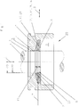
- FIG. 1 An embodiment of a sealing arrangement according to the invention is shown in a schematic representation.
- the seal assembly Figure 1 is used in a monotube shock absorber of a motor vehicle and comprises the first machine element 4, the second machine element 5 and the sealing ring 6, which seals the two spaces 2, 3 which are arranged adjacent to one another in the axial direction 1.
- the first machine element 4 is designed as a piston of the single-tube shock absorber 25, the second machine element 5 as a housing of the single-tube shock absorber 25, which surrounds the piston on the outer circumference.
- the piston is movable back and forth relative to the housing in the axial direction 1, the piston being enclosed by the housing at a radial distance.
- the sealing ring 6 is arranged in the gap 7 formed by the radial distance within the installation space 10.
- the sealing ring 6 comprises the dynamically stressed first sealing lip 8 and two further dynamically stressed sealing lips 20, 21, which are connected downstream of the first sealing lip 8 on the side axially facing away from the first space 2 to be sealed in a functional series connection.
- the sealing ring 6 is of circular design and comprises a first 11 and a second end face 12.
- the first end face 11 is the first space 2 to be sealed and the second end face 12 is the second space 3 to be sealed axially facing.
- the first space 2 forms the high-pressure space of the monotube shock absorber 25, the second space 3, in contrast, the low-pressure space.
- the second end face 12 of the sealing ring 6 is designed as a first contact surface 13, the first contact surface 13 abutting a second contact surface 14 which is part of the second machine element 5 and is arranged on the side of the second machine element 5 which faces the first contact surface 13.
- the contact surfaces 13 are each formed as an inclined plane 15, 16.
- the inner diameters of the sealing lips 8, 20, 21 are reduced radially towards one another in the direction of the surface 9 to be sealed by a displacement of the contact surfaces 13, 14.
- the contact surfaces 13, 14 shown here close with the imaginary radial plane 17, which cuts through the contact surfaces 13, 14 in the radial direction, in each case an angle ⁇ 1 , ⁇ 2 , which is 12 to 25 degrees.
- the first end face 11 is arranged axially opposite to the second end face 12 of the sealing ring 6 and extends in the radial direction 18 parallel to the imaginary radial plane 17. Due to the configuration of the end faces 11, 12 and the aforementioned angles of the contact surfaces 13, 14, the Sealing ring 6 has a greater thickness 19 radially on the inside in the axial direction 1 than on the outside circumference in the radial direction 18.
- the sealing ring 6 is made in one piece and of the same material and consists predominantly of an FKM material, which can optionally be filled with a wear-reducing and / or friction-reducing filler 24.
- the first machine element 4 moves analogously to the micro-vibrations relative to the second machine element 5 during the entire transport of the motor vehicle.
- the sealing lips 8, 20, 21 are insufficiently lubricated, in contrast to the intended use of the sealing arrangement, for example when the motor vehicle is driven on the road, the first machine element 4 axially differs from the second machine element 5 large amplitudes moved and thereby the sealing lips 8, 20, 21 are sufficiently lubricated.
- the sealing ring 6 is shown in its production-related state.
- the first machine element 4 to be sealed is shown invisibly in two-dot-dash lines.
- the first sealing lip 8 has an inner diameter that is smaller than the diameter of the surface 9 to be sealed of the first machine element 4. Due to this overlap, the first sealing lip 8 always surrounds the surface 9 to be sealed in a sealing manner under radial prestress.
- the diameter 22 of the sealing lip 20 arranged axially adjacent to the sealing lip 8 is the same or only very slightly smaller than the diameter of the surface to be sealed 9.
- the second sealing lip 20 encloses the surface 9 to be sealed without a differential pressure between the spaces 2, 3 with a very slight, if any, radial preload.
- the third sealing lip 21 has a larger diameter 23 than the surface 9 to be sealed, so that the third sealing lip 21 seals the surface 9 to be sealed only when there is a clear differential pressure between the spaces 2, 3 to be sealed, for example in the order of magnitude of 25 bar encloses.
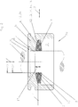
- Figure 2 is a section of the seal arrangement according to Figure 1 shown.
- the sealing arrangement is shown in the assembled state, the differential pressure between the rooms 2, 3 to be sealed being approximately 0 bar.
- the first sealing lip 8 surrounds the surface 9 to be sealed with a sufficiently large radial preload
- the second sealing lip 20 also surrounds the surface 9 to be sealed with a relatively lower radial preload
- the third sealing lip 21 surrounds the surface 9 to be sealed with a radial spacing; it does not touch the surface 9 to be sealed.
- Figure 3 is the excerpt from the Figures 1 and 2 shown, the differential pressure between the rooms to be sealed against each other 2, 3 is about 25 bar.
- the surface 9 to be sealed is sealingly enclosed by all three sealing lips 8, 20, 21 under radial prestressing, the radial prestressing of the first sealing lip 8 being greatest, the second sealing lip 20 being moderately large and the third sealing lip 21 being the smallest.
Landscapes
- Engineering & Computer Science (AREA)
- General Engineering & Computer Science (AREA)
- Mechanical Engineering (AREA)
- Sealing With Elastic Sealing Lips (AREA)
- Sealing Devices (AREA)
Claims (12)
- Agencement d'étanchéité pour l'étanchéité de deux espaces (2, 3) disposés l'un à côté de l'autre dans la direction axiale (1) et devant être étanchéifiés l'un par rapport à l'autre, comprenant un premier élément de machine (4), un deuxième élément de machine (5) et une bague d'étanchéité (6), le premier élément de machine (4) étant entouré à distance radiale par le deuxième élément de machine (5), et la bague d'étanchéité (6) étant disposée dans la fente (7) formée par la distance radiale, la bague d'étanchéité (6) présentant au moins une première lèvre d'étanchéité (8) sollicitée dynamiquement, qui entoure hermétiquement une surface à étanchéifier (9) du premier élément de machine (4), la bague d'étanchéité (6) étant disposée dans un espace d'installation (10) du deuxième élément de machine (5) et la bague d'étanchéité (6) présentant un premier (11) et un deuxième (12) côté frontal, parmi lesquels le premier côté frontal (11) est tourné axialement vers le premier espace (2) à étanchéifier et le deuxième côté frontal (12) est tourné axialement vers le deuxième espace (3) à étanchéifier, le premier espace (2) pouvant être sollicité par rapport au deuxième espace (3) avec une surpression relative, le deuxième côté frontal (12) étant réalisé sous forme de première surface de contact (13) de la bague d'étanchéité (6), le deuxième élément de machine (5) présentant une deuxième surface de contact (14) du côté tourné axialement vers la première surface de contact (13), et la première (13) et la deuxième (14) surface de contact étant en contact en appui l'une contre l'autre, caractérisé en ce que la première (13) et la deuxième (14) surface de contact sont réalisées de manière à coïncider l'une avec l'autre du fait de la fabrication, en ce que les surfaces de contact (13, 14) sont réalisées à chaque fois sous forme de plans obliques (15, 16) de telle sorte que lors d'un déplacement de la bague d'étanchéité (6) axialement dans la direction du deuxième espace (3), il se produise simultanément un mouvement relatif des deux surfaces de contact (13, 14) l'une vers l'autre et que le diamètre intérieur de l'au moins une lèvre d'étanchéité (8) entoure de manière hermétique la surface à étanchéifier (9) avec une précontrainte radiale croissante, les surfaces de contact (13, 14) formant à chaque fois un angle (α1, α2) compris entre 5° et 45° avec un plan radial imaginaire (17) qui passe à travers les surfaces de contact (13, 14).
- Agencement d'étanchéité selon la revendication 1, caractérisé en ce que les angles (α1, α2) valent à chaque fois 10° à 30°.
- Agencement d'étanchéité selon l'une quelconque des revendications 1 et 2, caractérisé en ce que le premier côté frontal (11) est disposé dans la direction radiale (18) parallèlement au plan radial imaginaire (17).
- Agencement d'étanchéité selon l'une quelconque des revendications 1 à 3, caractérisé en ce que la bague d'étanchéité (6) présente dans la direction axiale (1) une épaisseur croissante (19) dans la direction radiale (18) vers la première lèvre d'étanchéité (8).
- Agencement d'étanchéité selon l'une quelconque des revendications 1 à 4, caractérisé en ce qu'à la première lèvre d'étanchéité (8) est associée, de manière axialement adjacente dans un montage en série fonctionnel technique, axialement du côté tourné vers les surfaces de contact (13, 14), au moins une lèvre d'étanchéité supplémentaire sollicitée dynamiquement (20, 21).
- Agencement d'étanchéité selon la revendication 5, caractérisé en ce que les lèvres d'étanchéité supplémentaires (20, 21), présentent, par rapport à la première lèvre d'étanchéité (8), un plus grand diamètre (22, 23) plus elles sont proches des surfaces de contact (13, 14) dans la direction axiale (1).
- Agencement d'étanchéité selon l'une quelconque des revendications 1 à 6, caractérisé en ce que la bague d'étanchéité (6) est réalisée d'une seule pièce.
- Agencement d'étanchéité selon l'une quelconque des revendications 1 à 7, caractérisé en ce que la bague d'étanchéité (6) est réalisée de manière monobloc.
- Agencement d'étanchéité selon l'une quelconque des revendications 1 à 7, caractérisé en ce que le matériau constituant majoritairement la bague d'étanchéité (6) comprend une charge (24).
- Agencement d'étanchéité selon la revendication 9, caractérisé en ce que la charge (24) est réalisée de manière à réduire l'usure et/ou à réduire les frottements.
- Agencement d'étanchéité selon l'une quelconque des revendications 1 à 10, caractérisé en ce que la bague d'étanchéité (6) se compose au moins principalement d'un matériau à base de FKM.
- Utilisation d'un agencement d'étanchéité selon l'une quelconque des revendications 1 à 11 dans un amortisseur monotube (25).
Applications Claiming Priority (1)
| Application Number | Priority Date | Filing Date | Title |
|---|---|---|---|
| DE102016013638.3A DE102016013638B4 (de) | 2016-11-16 | 2016-11-16 | Dichtungsanordnung und deren Verwendung |
Publications (2)
| Publication Number | Publication Date |
|---|---|
| EP3324083A1 EP3324083A1 (fr) | 2018-05-23 |
| EP3324083B1 true EP3324083B1 (fr) | 2020-01-01 |
Family
ID=60301882
Family Applications (1)
| Application Number | Title | Priority Date | Filing Date |
|---|---|---|---|
| EP17201009.2A Active EP3324083B1 (fr) | 2016-11-16 | 2017-11-10 | Agencement d'étanchéité et son utilisation |
Country Status (3)
| Country | Link |
|---|---|
| US (1) | US10408351B2 (fr) |
| EP (1) | EP3324083B1 (fr) |
| DE (1) | DE102016013638B4 (fr) |
Families Citing this family (1)
| Publication number | Priority date | Publication date | Assignee | Title |
|---|---|---|---|---|
| DE102020106646B3 (de) * | 2020-03-11 | 2020-11-26 | Carl Freudenberg Kg | Dichtungsanordnung und deren Verwendung |
Family Cites Families (15)
| Publication number | Priority date | Publication date | Assignee | Title |
|---|---|---|---|---|
| US3218087A (en) * | 1962-07-09 | 1965-11-16 | Boeing Co | Foot seal |
| FR1438393A (fr) * | 1965-03-29 | 1966-05-13 | Joint d'étanchéité | |
| CH560340A5 (fr) * | 1973-02-09 | 1975-03-27 | Occident Etablissements | |
| DE3703360C2 (de) * | 1987-02-04 | 1993-11-18 | Knorr Bremse Ag | Dichtungsanordnung mit einem in eine Ringnut einsetzbaren Dichtungsring |
| DE3828692A1 (de) * | 1988-08-24 | 1990-03-15 | Busak & Luyken Gmbh & Co | Anordnung zum abdichten einer hin- und herbewegten stange |
| DE4104070A1 (de) * | 1991-02-11 | 1992-08-13 | Teves Gmbh Alfred | Bremszylinderdichtung mit ausnehmung |
| DE19728605C2 (de) | 1997-07-04 | 2000-03-02 | Freudenberg Carl Fa | Stangen- oder Kolbendichtung |
| JP3702416B2 (ja) * | 2000-03-16 | 2005-10-05 | 株式会社日立製作所 | 液圧緩衝器 |
| DE10102161B4 (de) | 2001-01-19 | 2006-06-22 | Wobben, Aloys, Dipl.-Ing. | Ringförmige Dichtung |
| JP2003049887A (ja) * | 2001-08-02 | 2003-02-21 | Showa Corp | 油圧緩衝器の軸封部構造及びその組立方法 |
| DE10151023C1 (de) * | 2001-10-16 | 2003-02-27 | Thyssen Krupp Bilstein Gmbh | Hydraulischer Stoßdämpfer |
| US6896110B2 (en) * | 2003-09-25 | 2005-05-24 | Tenneco Automotive Operating Company Inc. | Temperature compensated dual acting slip |
| EP2516189B1 (fr) * | 2009-12-21 | 2014-07-30 | Aktiebolaget SKF (publ) | Procédé et dispositif d'un système d'étanchéité |
| DE102011056692A1 (de) * | 2011-12-20 | 2013-06-20 | Parker Hannifin Manufacturing Germany GmbH & Co. KG | Dichtung mit Druckentlastungsfunktion |
| ITTO20130548A1 (it) * | 2013-07-01 | 2015-01-02 | Skf Ab | Complesso di tenuta a basso attrito per una unita¿ mozzo ruota ed unita¿ mozzo ruota equipaggiata con tale complesso di tenuta |
-
2016
- 2016-11-16 DE DE102016013638.3A patent/DE102016013638B4/de not_active Expired - Fee Related
-
2017
- 2017-11-10 EP EP17201009.2A patent/EP3324083B1/fr active Active
- 2017-11-15 US US15/813,170 patent/US10408351B2/en active Active
Non-Patent Citations (1)
| Title |
|---|
| None * |
Also Published As
| Publication number | Publication date |
|---|---|
| US10408351B2 (en) | 2019-09-10 |
| US20180135758A1 (en) | 2018-05-17 |
| DE102016013638B4 (de) | 2019-05-02 |
| EP3324083A1 (fr) | 2018-05-23 |
| DE102016013638A1 (de) | 2018-05-17 |
Similar Documents
| Publication | Publication Date | Title |
|---|---|---|
| EP2529134B1 (fr) | Ensemble joint d'étanchéité rotatif | |
| EP2035732B1 (fr) | Joint et ensemble joint | |
| EP2027403B1 (fr) | Structure d'étanchéite pour décompression | |
| DE2609446A1 (de) | Kugelventil | |
| EP3625484B1 (fr) | Arrangement de garniture d'étanchéité rotative et garniture d'étanchéité rotative avec fonction de refoulement | |
| EP3180550B1 (fr) | Dispositif d'étanchéité avec système d'amortissement | |
| EP0724693B1 (fr) | Dispositif d'étanchéité | |
| EP0491771B1 (fr) | Dispositif d'etancheite | |
| EP3324083B1 (fr) | Agencement d'étanchéité et son utilisation | |
| DE102008024163B4 (de) | Verbundkolben für ein Kraftfahrzeuggetriebe | |
| EP0573539B1 (fr) | Dispositif d'etancheite | |
| WO2016169965A1 (fr) | Ensemble piston-cylindre pour un compresseur à piston avec un segment d'étanchéité dynamique spécial | |
| EP1611380A1 (fr) | Ensemble joint | |
| DE102008029642A1 (de) | Tellerfederanordnung | |
| EP2963319A1 (fr) | Bague d'étanchéité | |
| DE102010052558A1 (de) | Dachmanschettenring für einen Dachmanschettendichtungssatz | |
| DE102020106646B3 (de) | Dichtungsanordnung und deren Verwendung | |
| EP3511590B1 (fr) | Joint d'étanchéité et dispositif d'étanchéité comprenant le joint d'étanchéité | |
| EP1687557B1 (fr) | Systeme d'assemblage | |
| DE2121067A1 (de) | Elastisches Lager, insbesondere für die Motoraufhängung in Kraftfahrzeugen | |
| DE19610809A1 (de) | Dichtungsanordnung | |
| DE102017003999B4 (de) | Stangendichtung | |
| DE10000084A1 (de) | Stützring zur Abstützung eines O-Rings | |
| EP1878953A1 (fr) | Dispositif d'étanchéité | |
| DE102023101557A1 (de) | Rückschlagventil, Schwingungsdämpfer mit einem solchen Rückschlagventil und Verwendung eines solchen Rückschlagventils |
Legal Events
| Date | Code | Title | Description |
|---|---|---|---|
| PUAI | Public reference made under article 153(3) epc to a published international application that has entered the european phase |
Free format text: ORIGINAL CODE: 0009012 |
|
| STAA | Information on the status of an ep patent application or granted ep patent |
Free format text: STATUS: THE APPLICATION HAS BEEN PUBLISHED |
|
| AK | Designated contracting states |
Kind code of ref document: A1 Designated state(s): AL AT BE BG CH CY CZ DE DK EE ES FI FR GB GR HR HU IE IS IT LI LT LU LV MC MK MT NL NO PL PT RO RS SE SI SK SM TR |
|
| AX | Request for extension of the european patent |
Extension state: BA ME |
|
| STAA | Information on the status of an ep patent application or granted ep patent |
Free format text: STATUS: REQUEST FOR EXAMINATION WAS MADE |
|
| RIN1 | Information on inventor provided before grant (corrected) |
Inventor name: WADDELL, PAUL Inventor name: DIXON, ROSS Inventor name: WATLING, SIMON Inventor name: BILLANY, MATT Inventor name: EMIG, JUERGEN |
|
| 17P | Request for examination filed |
Effective date: 20180801 |
|
| RBV | Designated contracting states (corrected) |
Designated state(s): AL AT BE BG CH CY CZ DE DK EE ES FI FR GB GR HR HU IE IS IT LI LT LU LV MC MK MT NL NO PL PT RO RS SE SI SK SM TR |
|
| RIN1 | Information on inventor provided before grant (corrected) |
Inventor name: WATLING, SIMON Inventor name: DIXON, ROSS Inventor name: BILLANY, MATT Inventor name: EMIG, JUERGEN Inventor name: WADDELL, PAUL |
|
| RIC1 | Information provided on ipc code assigned before grant |
Ipc: F16J 15/16 20060101AFI20190725BHEP |
|
| GRAP | Despatch of communication of intention to grant a patent |
Free format text: ORIGINAL CODE: EPIDOSNIGR1 |
|
| STAA | Information on the status of an ep patent application or granted ep patent |
Free format text: STATUS: GRANT OF PATENT IS INTENDED |
|
| INTG | Intention to grant announced |
Effective date: 20190904 |
|
| GRAS | Grant fee paid |
Free format text: ORIGINAL CODE: EPIDOSNIGR3 |
|
| GRAA | (expected) grant |
Free format text: ORIGINAL CODE: 0009210 |
|
| STAA | Information on the status of an ep patent application or granted ep patent |
Free format text: STATUS: THE PATENT HAS BEEN GRANTED |
|
| AK | Designated contracting states |
Kind code of ref document: B1 Designated state(s): AL AT BE BG CH CY CZ DE DK EE ES FI FR GB GR HR HU IE IS IT LI LT LU LV MC MK MT NL NO PL PT RO RS SE SI SK SM TR |
|
| REG | Reference to a national code |
Ref country code: GB Ref legal event code: FG4D Free format text: NOT ENGLISH |
|
| REG | Reference to a national code |
Ref country code: CH Ref legal event code: EP Ref country code: AT Ref legal event code: REF Ref document number: 1220173 Country of ref document: AT Kind code of ref document: T Effective date: 20200115 |
|
| REG | Reference to a national code |
Ref country code: IE Ref legal event code: FG4D Free format text: LANGUAGE OF EP DOCUMENT: GERMAN |
|
| REG | Reference to a national code |
Ref country code: DE Ref legal event code: R096 Ref document number: 502017003342 Country of ref document: DE |
|
| REG | Reference to a national code |
Ref country code: NL Ref legal event code: MP Effective date: 20200101 |
|
| REG | Reference to a national code |
Ref country code: LT Ref legal event code: MG4D |
|
| PG25 | Lapsed in a contracting state [announced via postgrant information from national office to epo] |
Ref country code: LT Free format text: LAPSE BECAUSE OF FAILURE TO SUBMIT A TRANSLATION OF THE DESCRIPTION OR TO PAY THE FEE WITHIN THE PRESCRIBED TIME-LIMIT Effective date: 20200101 Ref country code: PT Free format text: LAPSE BECAUSE OF FAILURE TO SUBMIT A TRANSLATION OF THE DESCRIPTION OR TO PAY THE FEE WITHIN THE PRESCRIBED TIME-LIMIT Effective date: 20200527 Ref country code: NL Free format text: LAPSE BECAUSE OF FAILURE TO SUBMIT A TRANSLATION OF THE DESCRIPTION OR TO PAY THE FEE WITHIN THE PRESCRIBED TIME-LIMIT Effective date: 20200101 Ref country code: CZ Free format text: LAPSE BECAUSE OF FAILURE TO SUBMIT A TRANSLATION OF THE DESCRIPTION OR TO PAY THE FEE WITHIN THE PRESCRIBED TIME-LIMIT Effective date: 20200101 Ref country code: FI Free format text: LAPSE BECAUSE OF FAILURE TO SUBMIT A TRANSLATION OF THE DESCRIPTION OR TO PAY THE FEE WITHIN THE PRESCRIBED TIME-LIMIT Effective date: 20200101 Ref country code: NO Free format text: LAPSE BECAUSE OF FAILURE TO SUBMIT A TRANSLATION OF THE DESCRIPTION OR TO PAY THE FEE WITHIN THE PRESCRIBED TIME-LIMIT Effective date: 20200401 Ref country code: RS Free format text: LAPSE BECAUSE OF FAILURE TO SUBMIT A TRANSLATION OF THE DESCRIPTION OR TO PAY THE FEE WITHIN THE PRESCRIBED TIME-LIMIT Effective date: 20200101 |
|
| PG25 | Lapsed in a contracting state [announced via postgrant information from national office to epo] |
Ref country code: HR Free format text: LAPSE BECAUSE OF FAILURE TO SUBMIT A TRANSLATION OF THE DESCRIPTION OR TO PAY THE FEE WITHIN THE PRESCRIBED TIME-LIMIT Effective date: 20200101 Ref country code: BG Free format text: LAPSE BECAUSE OF FAILURE TO SUBMIT A TRANSLATION OF THE DESCRIPTION OR TO PAY THE FEE WITHIN THE PRESCRIBED TIME-LIMIT Effective date: 20200401 Ref country code: GR Free format text: LAPSE BECAUSE OF FAILURE TO SUBMIT A TRANSLATION OF THE DESCRIPTION OR TO PAY THE FEE WITHIN THE PRESCRIBED TIME-LIMIT Effective date: 20200402 Ref country code: IS Free format text: LAPSE BECAUSE OF FAILURE TO SUBMIT A TRANSLATION OF THE DESCRIPTION OR TO PAY THE FEE WITHIN THE PRESCRIBED TIME-LIMIT Effective date: 20200501 Ref country code: SE Free format text: LAPSE BECAUSE OF FAILURE TO SUBMIT A TRANSLATION OF THE DESCRIPTION OR TO PAY THE FEE WITHIN THE PRESCRIBED TIME-LIMIT Effective date: 20200101 Ref country code: LV Free format text: LAPSE BECAUSE OF FAILURE TO SUBMIT A TRANSLATION OF THE DESCRIPTION OR TO PAY THE FEE WITHIN THE PRESCRIBED TIME-LIMIT Effective date: 20200101 |
|
| REG | Reference to a national code |
Ref country code: DE Ref legal event code: R097 Ref document number: 502017003342 Country of ref document: DE |
|
| PG25 | Lapsed in a contracting state [announced via postgrant information from national office to epo] |
Ref country code: EE Free format text: LAPSE BECAUSE OF FAILURE TO SUBMIT A TRANSLATION OF THE DESCRIPTION OR TO PAY THE FEE WITHIN THE PRESCRIBED TIME-LIMIT Effective date: 20200101 Ref country code: SM Free format text: LAPSE BECAUSE OF FAILURE TO SUBMIT A TRANSLATION OF THE DESCRIPTION OR TO PAY THE FEE WITHIN THE PRESCRIBED TIME-LIMIT Effective date: 20200101 Ref country code: DK Free format text: LAPSE BECAUSE OF FAILURE TO SUBMIT A TRANSLATION OF THE DESCRIPTION OR TO PAY THE FEE WITHIN THE PRESCRIBED TIME-LIMIT Effective date: 20200101 Ref country code: RO Free format text: LAPSE BECAUSE OF FAILURE TO SUBMIT A TRANSLATION OF THE DESCRIPTION OR TO PAY THE FEE WITHIN THE PRESCRIBED TIME-LIMIT Effective date: 20200101 Ref country code: ES Free format text: LAPSE BECAUSE OF FAILURE TO SUBMIT A TRANSLATION OF THE DESCRIPTION OR TO PAY THE FEE WITHIN THE PRESCRIBED TIME-LIMIT Effective date: 20200101 Ref country code: SK Free format text: LAPSE BECAUSE OF FAILURE TO SUBMIT A TRANSLATION OF THE DESCRIPTION OR TO PAY THE FEE WITHIN THE PRESCRIBED TIME-LIMIT Effective date: 20200101 |
|
| PLBE | No opposition filed within time limit |
Free format text: ORIGINAL CODE: 0009261 |
|
| STAA | Information on the status of an ep patent application or granted ep patent |
Free format text: STATUS: NO OPPOSITION FILED WITHIN TIME LIMIT |
|
| 26N | No opposition filed |
Effective date: 20201002 |
|
| PG25 | Lapsed in a contracting state [announced via postgrant information from national office to epo] |
Ref country code: IT Free format text: LAPSE BECAUSE OF FAILURE TO SUBMIT A TRANSLATION OF THE DESCRIPTION OR TO PAY THE FEE WITHIN THE PRESCRIBED TIME-LIMIT Effective date: 20200101 |
|
| PG25 | Lapsed in a contracting state [announced via postgrant information from national office to epo] |
Ref country code: SI Free format text: LAPSE BECAUSE OF FAILURE TO SUBMIT A TRANSLATION OF THE DESCRIPTION OR TO PAY THE FEE WITHIN THE PRESCRIBED TIME-LIMIT Effective date: 20200101 Ref country code: PL Free format text: LAPSE BECAUSE OF FAILURE TO SUBMIT A TRANSLATION OF THE DESCRIPTION OR TO PAY THE FEE WITHIN THE PRESCRIBED TIME-LIMIT Effective date: 20200101 |
|
| PG25 | Lapsed in a contracting state [announced via postgrant information from national office to epo] |
Ref country code: MC Free format text: LAPSE BECAUSE OF FAILURE TO SUBMIT A TRANSLATION OF THE DESCRIPTION OR TO PAY THE FEE WITHIN THE PRESCRIBED TIME-LIMIT Effective date: 20200101 |
|
| REG | Reference to a national code |
Ref country code: CH Ref legal event code: PL |
|
| PG25 | Lapsed in a contracting state [announced via postgrant information from national office to epo] |
Ref country code: LU Free format text: LAPSE BECAUSE OF NON-PAYMENT OF DUE FEES Effective date: 20201110 |
|
| REG | Reference to a national code |
Ref country code: BE Ref legal event code: MM Effective date: 20201130 |
|
| PG25 | Lapsed in a contracting state [announced via postgrant information from national office to epo] |
Ref country code: CH Free format text: LAPSE BECAUSE OF NON-PAYMENT OF DUE FEES Effective date: 20201130 Ref country code: LI Free format text: LAPSE BECAUSE OF NON-PAYMENT OF DUE FEES Effective date: 20201130 |
|
| PG25 | Lapsed in a contracting state [announced via postgrant information from national office to epo] |
Ref country code: IE Free format text: LAPSE BECAUSE OF NON-PAYMENT OF DUE FEES Effective date: 20201110 Ref country code: FR Free format text: LAPSE BECAUSE OF NON-PAYMENT OF DUE FEES Effective date: 20201130 |
|
| PG25 | Lapsed in a contracting state [announced via postgrant information from national office to epo] |
Ref country code: TR Free format text: LAPSE BECAUSE OF FAILURE TO SUBMIT A TRANSLATION OF THE DESCRIPTION OR TO PAY THE FEE WITHIN THE PRESCRIBED TIME-LIMIT Effective date: 20200101 Ref country code: MT Free format text: LAPSE BECAUSE OF FAILURE TO SUBMIT A TRANSLATION OF THE DESCRIPTION OR TO PAY THE FEE WITHIN THE PRESCRIBED TIME-LIMIT Effective date: 20200101 Ref country code: CY Free format text: LAPSE BECAUSE OF FAILURE TO SUBMIT A TRANSLATION OF THE DESCRIPTION OR TO PAY THE FEE WITHIN THE PRESCRIBED TIME-LIMIT Effective date: 20200101 |
|
| PG25 | Lapsed in a contracting state [announced via postgrant information from national office to epo] |
Ref country code: MK Free format text: LAPSE BECAUSE OF FAILURE TO SUBMIT A TRANSLATION OF THE DESCRIPTION OR TO PAY THE FEE WITHIN THE PRESCRIBED TIME-LIMIT Effective date: 20200101 Ref country code: AL Free format text: LAPSE BECAUSE OF FAILURE TO SUBMIT A TRANSLATION OF THE DESCRIPTION OR TO PAY THE FEE WITHIN THE PRESCRIBED TIME-LIMIT Effective date: 20200101 |
|
| GBPC | Gb: european patent ceased through non-payment of renewal fee |
Effective date: 20211110 |
|
| PG25 | Lapsed in a contracting state [announced via postgrant information from national office to epo] |
Ref country code: BE Free format text: LAPSE BECAUSE OF NON-PAYMENT OF DUE FEES Effective date: 20201130 |
|
| PG25 | Lapsed in a contracting state [announced via postgrant information from national office to epo] |
Ref country code: GB Free format text: LAPSE BECAUSE OF NON-PAYMENT OF DUE FEES Effective date: 20211110 |
|
| REG | Reference to a national code |
Ref country code: AT Ref legal event code: MM01 Ref document number: 1220173 Country of ref document: AT Kind code of ref document: T Effective date: 20221110 |
|
| PG25 | Lapsed in a contracting state [announced via postgrant information from national office to epo] |
Ref country code: AT Free format text: LAPSE BECAUSE OF NON-PAYMENT OF DUE FEES Effective date: 20221110 |
|
| PGFP | Annual fee paid to national office [announced via postgrant information from national office to epo] |
Ref country code: DE Payment date: 20251126 Year of fee payment: 9 |