EP3324729B1 - Dispositif de climatisation pour une serre - Google Patents
Dispositif de climatisation pour une serre Download PDFInfo
- Publication number
- EP3324729B1 EP3324729B1 EP16751188.0A EP16751188A EP3324729B1 EP 3324729 B1 EP3324729 B1 EP 3324729B1 EP 16751188 A EP16751188 A EP 16751188A EP 3324729 B1 EP3324729 B1 EP 3324729B1
- Authority
- EP
- European Patent Office
- Prior art keywords
- cooling
- condenser
- condensation device
- tubular
- hollow bodies
- Prior art date
- Legal status (The legal status is an assumption and is not a legal conclusion. Google has not performed a legal analysis and makes no representation as to the accuracy of the status listed.)
- Active
Links
Images



Classifications
-
- A—HUMAN NECESSITIES
- A01—AGRICULTURE; FORESTRY; ANIMAL HUSBANDRY; HUNTING; TRAPPING; FISHING
- A01G—HORTICULTURE; CULTIVATION OF VEGETABLES, FLOWERS, RICE, FRUIT, VINES, HOPS OR SEAWEED; FORESTRY; WATERING
- A01G9/00—Cultivation in receptacles, forcing-frames or greenhouses; Edging for beds, lawn or the like
- A01G9/24—Devices or systems for heating, ventilating, regulating temperature, illuminating, or watering, in greenhouses, forcing-frames, or the like
-
- A—HUMAN NECESSITIES
- A01—AGRICULTURE; FORESTRY; ANIMAL HUSBANDRY; HUNTING; TRAPPING; FISHING
- A01G—HORTICULTURE; CULTIVATION OF VEGETABLES, FLOWERS, RICE, FRUIT, VINES, HOPS OR SEAWEED; FORESTRY; WATERING
- A01G9/00—Cultivation in receptacles, forcing-frames or greenhouses; Edging for beds, lawn or the like
- A01G9/24—Devices or systems for heating, ventilating, regulating temperature, illuminating, or watering, in greenhouses, forcing-frames, or the like
- A01G9/246—Air-conditioning systems
-
- B—PERFORMING OPERATIONS; TRANSPORTING
- B01—PHYSICAL OR CHEMICAL PROCESSES OR APPARATUS IN GENERAL
- B01D—SEPARATION
- B01D5/00—Condensation of vapours; Recovering volatile solvents by condensation
- B01D5/0003—Condensation of vapours; Recovering volatile solvents by condensation by using heat-exchange surfaces for indirect contact between gases or vapours and the cooling medium
- B01D5/0009—Horizontal tubes
-
- B—PERFORMING OPERATIONS; TRANSPORTING
- B01—PHYSICAL OR CHEMICAL PROCESSES OR APPARATUS IN GENERAL
- B01D—SEPARATION
- B01D5/00—Condensation of vapours; Recovering volatile solvents by condensation
- B01D5/0003—Condensation of vapours; Recovering volatile solvents by condensation by using heat-exchange surfaces for indirect contact between gases or vapours and the cooling medium
- B01D5/0012—Vertical tubes
-
- F—MECHANICAL ENGINEERING; LIGHTING; HEATING; WEAPONS; BLASTING
- F28—HEAT EXCHANGE IN GENERAL
- F28B—STEAM OR VAPOUR CONDENSERS
- F28B1/00—Condensers in which the steam or vapour is separate from the cooling medium by walls, e.g. surface condenser
-
- Y—GENERAL TAGGING OF NEW TECHNOLOGICAL DEVELOPMENTS; GENERAL TAGGING OF CROSS-SECTIONAL TECHNOLOGIES SPANNING OVER SEVERAL SECTIONS OF THE IPC; TECHNICAL SUBJECTS COVERED BY FORMER USPC CROSS-REFERENCE ART COLLECTIONS [XRACs] AND DIGESTS
- Y02—TECHNOLOGIES OR APPLICATIONS FOR MITIGATION OR ADAPTATION AGAINST CLIMATE CHANGE
- Y02A—TECHNOLOGIES FOR ADAPTATION TO CLIMATE CHANGE
- Y02A40/00—Adaptation technologies in agriculture, forestry, livestock or agroalimentary production
- Y02A40/10—Adaptation technologies in agriculture, forestry, livestock or agroalimentary production in agriculture
- Y02A40/25—Greenhouse technology, e.g. cooling systems therefor
Definitions
- the invention relates to a cooling and condensation device for a greenhouse, preferably a foil greenhouse, with at least one condenser arranged in the greenhouse, the wall of which is in contact on the outside with the air to be cooled in the greenhouse and a cooling medium is applied to the inside.
- the greenhouse described here has a heat exchanger device with a total of three pairs of pipelines, which are suspended via a carrier device on a support structure above the plant space of the greenhouse.
- the pipelines are spiral rib tubes with radially protruding spiral ribs, the pipelines being able to be adjusted by means of the carrier device between an upper position, in the head area of the plants, and a lower position, in the area of plant troughs.
- cooling water which preferably has a temperature below the dew point of the air in the greenhouse, flows through the pipelines; in cooling mode, the pipelines are in the upper position, in the head area of the plants, so that the warm, moist air rising in the greenhouse the pipelines can flow around. This means that the humidity contained in the air condenses on the pipes.
- the condensate can be fed to the plants.
- the heat exchange device is relatively bulky and heavy, especially when the weight of the cooling water is taken into account, so that installation in lightweight greenhouses or foil greenhouses would not be possible without additional support elements.
- the object of the invention is to propose a cooling and condensation device for a greenhouse, which is simple and inexpensive Manufacture distinguishes itself, whereby the possibility of retrofitting existing greenhouses and the problem-free use in foil greenhouses should be given.
- the at least one capacitor is designed as a foldable film tube and in particular consists of lined up hollow bodies made of a foldable film material, the tubular capacitor being unfolded from a folded storage shape into an elongated operating shape.
- the advantage of the invention is in particular that instead of the rigid, heavy structure of the WO 2015/028470 known device, which with its spiral tubes and suspension devices must be adapted to the special shape and dimensions of a greenhouse, lightweight, completely flexible capacitors made of a foldable plastic film material are used, which are kept in the folded state and only when assembled in the greenhouse - similar to a bellows - to be unfolded.
- the dismantling of the cooling and condensation device offers a further advantage, since essential parts, namely the tubular condensers made of foil material, can be recycled and therefore no cleaning and storage of these parts is necessary at the end of the season.
- the individual hollow bodies of the capacitor preferably consist of the lateral surfaces of straight truncated pyramids or truncated cones which have a base edge and a collar-shaped transition opening to the adjacent hollow body, the truncated pyramids or truncated cones being connected to one another at their base edges and collars.
- the basic structure can be triangular, square or also hexagonal, with hollow bodies in the form of a double truncated cone also being possible.
- the hollow bodies of the condenser have a square cross-sectional area and form a flat, octahedral body, with two opposite, blunt corners being cut off to form the transfer openings for the cooling medium.
- the cooling and condensation device There are two main design variants for the cooling and condensation device according to the invention, in a first variant the at least one tubular condenser or several capacitors arranged parallel to one another are fastened in a horizontal position in the greenhouse, as well as a second design variant in which the tubular condensers are in in a vertical orientation hanging freely from the ceiling in a greenhouse.
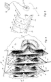
- the illustrated embodiment variant of a cooling and condensation device 10 for a greenhouse 1 with a foil-covered metal frame 2 has at least one, essentially horizontally arranged, tubular condenser 11 (whereby several condensers 11 arranged parallel next to one another are of course advantageous), the wall of which on the Outside 21 is in contact with the air to be cooled in the greenhouse 1 and a cooling medium is applied to the inside 22.
- the tubular Capacitors 11 consist, for example, of lined up hollow bodies 12 made of a foldable film material, which starting from a compact, folded-up storage form (see Fig. 3 ) in the e.g. in the FIGS. 1 and 2 shown elongated operating form can be unfolded.
- the length of the film tube can - compared to the operating form - be shortened by 70% to 95%.
- the hollow bodies 12 of the condenser 11 consist, for example, of the lateral surfaces 13 of straight truncated pyramids or truncated cones, each of which has a base edge 14 and a collar 15 forming a transition opening 16 to the adjacent hollow body 12, the pyramids - Or truncated cones are connected to one another at their base edges 14 and collars 15.
- the hollow bodies 12 of the capacitor 11 have a square cross-sectional area and form a flat, octahedral body, with two opposite, blunt corners being cut off to form the transfer openings 16 for the cooling medium (see FIG Fig. 4 ).
- Fastening means 17, 18 are provided for the horizontal mounting of the tubular condensers 11 in the greenhouse 1, a connecting flange 23 being formed at the inlet end and at the outlet end of each tubular condenser 11, which is connected to a passage opening in a wall, for example the front wall 3 and the rear wall 4 of greenhouse 1, can be connected (see FIGS. 1 and 2 ).
- hooks 17 which are fastened to the hollow bodies 12 and which engage in a support cable 18, preferably made of plastic, can be provided.
- the support cable 18 can be attached to the two connection flanges 23, for example.
- a separating surface 19 which is normal to the longitudinal axis 11 'of the condenser 11 and which has through openings 20 on the edge for the air used as the cooling medium, preferably ambient or outside air (see Fig. 4 , Arrows 35).
- the air used as the cooling medium preferably ambient or outside air (see Fig. 4 , Arrows 35).
- the air flow is deflected several times, the flow path is lengthened and the cooling effect is increased.
- the condensate 36 dripping off the outside 21 of the condenser 11.
- the separating surfaces 19 arranged in the interior of the hollow bodies 12 have a greater wall thickness or are designed to be more rigid than the flexible jacket surface 13 and therefore exercise a support function for the hollow bodies 12 in their elongated operating form.
- a ventilation device 24 is arranged on or in at least one connection flange 23 of the condenser 11, with which a cooling air flow can be produced through the condenser 11 in the pressure direction or suction direction.
- the ventilation device 24 can preferably be driven with the electrical energy from a solar panel 25.
- an inflatable collecting channel 26 for receiving the condensate 36 accumulating on the outside 21 of the condenser 11 can be attached.
- the collecting channel 26 consists of a film material and has inflatable, tubular chambers 27 arranged at the edge, on which holding elements 28 engage, which are fastened to the hollow bodies 12 of the tubular capacitor 11.
- the collecting channels 26 can also be recycled at the end of the season.
- Fig. 6 shows a flat film element for producing a hollow body 12 of the tubular capacitor 11, which is punched or cut out of a plastic film and after welding or gluing along the edges 40 results in the outer surface 13 of a square, square truncated pyramid.
- the four trapezoidal surfaces each have an acute angle of approx. 50 °.
- the individual hollow bodies 12 according to Fig. 7 consist of a first truncated pyramid A and a second truncated pyramid B, the base edges 14 of which are welded or glued to one another with the interposition of a separating surface 19 together with edge-side passage openings 20 for the cooling air. Finally, the individual hollow bodies 12 are welded or glued together on the collar 15, which forms the transition opening 16.
- FIG Fig. 6 It is also possible to use two flat film elements according to FIG Fig. 6 to be placed on top of each other and first welded or glued to the collar line 15. The two film elements are then pulled up in opposite directions and welded at the edges 40. The elements produced in this way are then connected to one another to form a tubular capacitor 11 with a separating surface 19 in between.
- the illustrated embodiment variant of a cooling and condensation device 10 for a greenhouse 1 with a foil-covered metal frame 2 has at least one, essentially vertically arranged, tubular condenser 11 (although several condensers 11 arranged in parallel are also advantageous here), the wall of which is in contact on the outside 21 with the air to be cooled in the greenhouse 1 and on the inside 22 with a cooling medium (cooling water 37 in Drop shape) is applied.
- the tubular capacitors 11 consist, for example - as described above - of concatenated hollow bodies 12 made of a foldable film material which, starting from a compact, folded-up storage form (see FIG Fig. 3 ) into the in Fig. 8 shown elongated operating form can be unfolded.
- a cooling water tank 29 is formed, which has openings 30 on the bottom for discharging cooling water 37 in the form of drops into the Has interior of the tubular capacitor 11.
- the cooling water released in the form of drops drips onto the inside 22 of the hollow bodies 12 made of film material and flows off along the inner surface.
- condensate 36 forms on the outside of the condenser and, in simple design variants, drips directly onto the plants in greenhouse 1.
- a collecting container 31 for the cooling water can be formed at the outlet end of the tubular condenser 11, preferably at an end connection flange 23, with a return device 32 for the cooling water being provided, starting from the collecting container 31, which opens into the cooling water container 29 arranged on the inlet side.
- the return device 32 can be equipped with a cooling water pump 33, which is preferably operated by means of solar energy.
- support cables 18, preferably made of plastic, are stretched between the inlet-side and outlet-side connection flange 23.
- no separating surfaces 19 are provided.
- a collecting pan 34 for receiving the condensate 36 accumulating on the outside 21 of the condenser 11 can be attached to the outlet end of the tubular condenser 11.
- the collecting trough 34 is formed by a circumferential wall 38 of the lower connection flange 23 and has a drainage hose 39.
- Fig. 10 shows a transition element 41 of the vertical capacitor 11 made of foil material which can be welded or glued between (only schematically indicated) adjacent hollow bodies 12 in order to round off the transition on the collar 15 forming the transition opening 16. This measure improves the wetting of the inside of the condenser 11 and prevents the cooling water from dripping off the collar 15.
- the collapsible, tubular condenser 11 can according to FIG Fig. 11 can be formed from several (four in the variant shown) film strips 42 which are welded or glued together at the side edges 43, which are jagged, for example, at an angle of approximately 100 °. Connection flanges 23 are then attached to the ends 44.
Landscapes
- Life Sciences & Earth Sciences (AREA)
- Environmental Sciences (AREA)
- Greenhouses (AREA)
- Heat-Exchange Devices With Radiators And Conduit Assemblies (AREA)
- Fixed Capacitors And Capacitor Manufacturing Machines (AREA)
- Vaporization, Distillation, Condensation, Sublimation, And Cold Traps (AREA)
Claims (17)
- Dispositif de refroidissement et de condensation (10) pour une serre (1), de préférence une serre en feuilles, doté d'au moins un condensateur (11) monté dont la paroi sur le côté extérieur (21) est en contact avec l'air à refroidir et auquel peut être appliqué, sur le côté intérieur (22), un milieu de refroidissement, caractérisé en ce que ledit au moins un condensateur (11) est réalisé en tant que tube en feuilles pliable et est composé notamment de corps creux (12) mis bout à bout, en matériau en feuilles pliable, ledit condensateur (11) de forme tubulaire pouvant être déplié pour passer d'une forme de stockage pliée en une forme d'utilisation allongée.
- Dispositif de refroidissement et de condensation (10) selon la revendication 1, caractérisé en ce que les corps creux (12) du condensateur (11) se composent des surfaces d'enveloppe (13) de troncs de pyramide ou troncs de cône droits qui présentent chacun un bord de base (14) et une collerette (15) formant une ouverture de déversement (16) vers le corps creux voisin (12), lesdits troncs de pyramide ou troncs de cône étant reliés les uns aux autres chacun au niveau de leurs bords de base (14) et collerettes (15).
- Dispositif de refroidissement et de condensation (10) selon la revendication 2, caractérisé en ce que les corps creux (12) du condensateur (11) présentent une surface de section quadratique et forment un corps plat de forme octaédrale, deux coins obtus en vis à vis étant découpés pour former les ouvertures de déversement (16).
- Dispositif de refroidissement et de condensation (10) selon l'une quelconque des revendications 1 à 3, caractérisé en ce que ledit au moins un condensateur (11) de forme tubulaire présente des moyens de fixation (17, 18) destinés au montage horizontal.
- Dispositif de refroidissement et de condensation (10) selon la revendication 4, caractérisé en ce qu'une surface de séparation (19) située de façon normale sur l'axe longitudinal (11') du condensateur (11) est agencée respectivement à l'intérieur des corps creux (12) au niveau du bord de base (14), laquelle surface de séparation présente des ouvertures de passage (20) périphériques pour l'air utilisé en tant que milieu de refroidissement, de préférence de l'air extérieur.
- Dispositif de refroidissement et de condensation (10) selon la revendication 5, caractérisé en ce que les surfaces de séparation (19) agencées à l'intérieur des corps creux (12) présentent une épaisseur de paroi plus importante ou sont conçus plus rigides que la surface d'enveloppe (13) et qu'elles exercent une fonction de soutien pour les corps creux (12) dans leur forme d'utilisation allongée.
- Dispositif de refroidissement et de condensation (10) selon l'une quelconque des revendications 4 à 6,
caractérisé en ce qu'une bride de raccordement (23), qui peut être raccordée à une ouverture de passage dans une paroi (3, 4) d'une serre (1), est formée respectivement à l'extrémité d'entrée et à l'extrémité de sortie de chaque condensateur (11) de forme tubulaire. - Dispositif de refroidissement et de condensation (10) selon l'une quelconque des revendications 4 à 7,
caractérisé en ce que des crochets (17), en prise dans un câble porteur (18), de préférence en matière plastique, et fixés aux corps creux (12) sont prévus en tant que moyens de fixation du condensateur (11) de forme tubulaire. - Dispositif de refroidissement et de condensation (10) selon la revendication 7 ou 8, caractérisé en ce qu'un dispositif de ventilation (24), avec lequel un courant d'air de refroidissement peut être généré au travers du condensateur (11), est agencé sur ou dans au moins une bride de raccordement (23) du condensateur (11).
- Dispositif de refroidissement et de condensation (10) selon l'une quelconque des revendications 4 à 9, caractérisé en ce que, en position d'utilisation, une rigole collectrice (26) gonflable est fixée au-dessous du condensateur (11) de forme tubulaire pour recueillir le condensat se formant sur le côté extérieur (21) du condensateur (11).
- Dispositif de refroidissement et de condensation (10) selon la revendication 10, caractérisé en ce que ladite rigole collectrice (26) se compose d'un matériau en feuilles et présente des chambres (27) de forme tubulaires, agencées en périphérie et gonflables, dans lesquelles sont en prise des éléments de maintien (28) qui sont fixés au corps creux (12) du condensateur de forme tubulaire.
- Dispositif de refroidissement et de condensation (10) selon l'une quelconque des revendications 1 à 3, caractérisé en ce que ledit au moins un condensateur (11) de forme tubulaire présente des moyens de fixation (18, 23) destinés au montage vertical.
- Dispositif de refroidissement et de condensation (10) selon la revendication 12, caractérisé en ce qu'est conçu, à l'extrémité d'entrée du condensateur (11) de forme tubulaire, de préférence à une bride de raccordement (23), un récipient d'eau de refroidissement (29) qui présente des ouvertures (30) en son fond pour distribuer de l'eau de refroidissement sous forme de gouttes dans l'intérieur du condensateur (11) de forme tubulaire, de sorte que ladite eau de refroidissement distribuée sous forme de gouttes s'égoutte sur le côté intérieur (22) des corps creux (12) en matériau en feuilles et s'écoule le long de la surface intérieure.
- Dispositif de refroidissement et de condensation (10) selon la revendication 12 ou 13, caractérisé en ce qu'à l'extrémité de sortie du condensateur (11) de forme tubulaire, de préférence à une bride de raccordement (23), un récipient (31) est conçu pour récupérer l'eau de refroidissement, ainsi qu'en ce qu'un dispositif de retour (32) de l'eau de refroidissement débouchant dans le récipient d'eau de refroidissement (29) agencé du côté de l'entrée est prévu à partir du récipient de récupération (31).
- Dispositif de refroidissement et de condensation (10) selon la revendication 14, caractérisé en ce que le dispositif de retour (32) de l'eau de refroidissement présente une pompe à eau de refroidissement (33) fonctionnant de préférence à l'énergie solaire.
- Dispositif de refroidissement et de condensation (10) selon la revendication 14 ou 15, caractérisé en ce que des câbles porteurs (18), de préférence en matière plastique, qui délimitent l'étirement longitudinal du condensateur (11) de forme tubulaire, sont tendus entre la bride de raccordement (23) du côté de l'entrée et celle du côté de la sortie.
- Dispositif de refroidissement et de condensation (10) selon l'une quelconque des revendications 12 à 16, caractérisé en ce qu'une cuvette de rétention (34) est fixée à l'extrémité de sortie du condensateur (11) de forme tubulaire pour recueillir le condensat se formant sur le côté extérieur (21) du condensateur (11).
Applications Claiming Priority (2)
| Application Number | Priority Date | Filing Date | Title |
|---|---|---|---|
| ATA50641/2015A AT517237B1 (de) | 2015-07-21 | 2015-07-21 | Kühl- und kondensationseinrichtung für ein gewächshaus |
| PCT/EP2016/067173 WO2017013112A1 (fr) | 2015-07-21 | 2016-07-19 | Dispositif de refroidissement et de condensation pour une serre |
Publications (2)
| Publication Number | Publication Date |
|---|---|
| EP3324729A1 EP3324729A1 (fr) | 2018-05-30 |
| EP3324729B1 true EP3324729B1 (fr) | 2021-03-17 |
Family
ID=56684587
Family Applications (1)
| Application Number | Title | Priority Date | Filing Date |
|---|---|---|---|
| EP16751188.0A Active EP3324729B1 (fr) | 2015-07-21 | 2016-07-19 | Dispositif de climatisation pour une serre |
Country Status (8)
| Country | Link |
|---|---|
| US (1) | US10881053B2 (fr) |
| EP (1) | EP3324729B1 (fr) |
| CN (1) | CN107920476B (fr) |
| AT (1) | AT517237B1 (fr) |
| AU (1) | AU2016295011B2 (fr) |
| BR (1) | BR112018001334B1 (fr) |
| ES (1) | ES2874797T3 (fr) |
| WO (1) | WO2017013112A1 (fr) |
Families Citing this family (2)
| Publication number | Priority date | Publication date | Assignee | Title |
|---|---|---|---|---|
| WO2020060402A1 (fr) * | 2018-09-20 | 2020-03-26 | B. Van Den Berg Holding B.V. | Serre comportant un système de régulation de climatisation, système de régulation de climatisation et procédé de fonctionnement de la serre |
| AT521950B1 (de) * | 2018-11-26 | 2020-06-15 | Kerschgens Daniel | Kühl- und/oder Kondensationseinrichtung für einen Innenraum |
Family Cites Families (30)
| Publication number | Priority date | Publication date | Assignee | Title |
|---|---|---|---|---|
| US2625872A (en) * | 1947-12-03 | 1953-01-20 | Follansbee Rogers | Air circulating unit |
| US2804284A (en) * | 1953-04-03 | 1957-08-27 | Griscom Russell Co | Heat exchanger |
| US3359687A (en) * | 1964-08-17 | 1967-12-26 | Haveg Industries Inc | Expansible seal |
| US4163342A (en) * | 1978-03-24 | 1979-08-07 | General Electric Company | Controlled environment agriculture facility and method for its operation |
| US4290242A (en) * | 1979-03-23 | 1981-09-22 | Gregory Jr William T | Greenhouse tubular insulation barrier |
| US4291499A (en) * | 1979-08-14 | 1981-09-29 | Prewer John R | Propagation of plants |
| US4352259A (en) * | 1980-03-24 | 1982-10-05 | X. S. Smith, Inc. | Movable inflatable ceiling or partition for greenhouse use |
| EP0097051A1 (fr) * | 1982-06-11 | 1983-12-28 | Mortimer Technology Limited | Ecran |
| US4672888A (en) * | 1985-01-03 | 1987-06-16 | Insul-Rib, Inc. | Inflatable greenhouse vent cover |
| NL194529C (nl) * | 1990-08-24 | 2002-07-02 | Wiebe Jan Boter | Inrichting voor het kweken van een gewas in een in hoofdzaak gesloten ruimte. |
| JP2001201286A (ja) * | 2000-01-21 | 2001-07-27 | Mitsubishi Heavy Ind Ltd | 熱交換チューブ |
| CN2428969Y (zh) * | 2000-06-08 | 2001-05-09 | 北京市富通环境工程公司 | 温室高效地中热交换装置 |
| US6442903B1 (en) * | 2000-11-13 | 2002-09-03 | Thomas H. Hebert | Inflatable insulative covering |
| CN1312450A (zh) * | 2001-02-28 | 2001-09-12 | 任春严 | 节水、节能的装置和方法 |
| DE10223578A1 (de) | 2002-05-27 | 2003-12-24 | Hubert Hamm | Vorrichtung zur Brauchwassergewinnung |
| US20040099408A1 (en) * | 2002-11-26 | 2004-05-27 | Shabtay Yoram Leon | Interconnected microchannel tube |
| US20040194371A1 (en) * | 2003-04-02 | 2004-10-07 | Kinnis Ralph Arthur | Greenhouse climate control system |
| CA2432097C (fr) * | 2003-06-12 | 2008-04-15 | Jean-Guy Dube | Barriere de ventilation |
| KR100672778B1 (ko) * | 2005-05-30 | 2007-01-22 | 김명한 | 농업용 열교환 합성수지 |
| GB0519791D0 (en) * | 2005-09-29 | 2005-11-09 | Cote Eric | Inflatable insulating panel |
| US8397434B2 (en) * | 2006-03-28 | 2013-03-19 | David Bayne | Greenhouse insulation system |
| GB2472041A (en) * | 2009-07-22 | 2011-01-26 | Questor Group Ltd C | Greenhouse having a system of watering by collecting condensate |
| JP2011252619A (ja) * | 2010-05-31 | 2011-12-15 | Pura Giken:Kk | 熱交換用パイプ |
| CN202101592U (zh) * | 2011-03-30 | 2012-01-04 | 鹿泽海 | 实用新型换热器 |
| CN202420220U (zh) * | 2011-12-26 | 2012-09-05 | 北京广厦环能科技有限公司 | 螺旋折流板波纹管冷凝器 |
| DE102013217286B4 (de) * | 2013-08-29 | 2015-04-30 | Humboldt-Universität Zu Berlin | Wärmetauschereinrichtung für ein Gewächshaus |
| NL2011966C2 (nl) * | 2013-12-16 | 2015-06-17 | Maurice Kassenbouw B V | Warenhuis en werkwijze voor klimaatbeheersing in een warenhuis. |
| CN204006817U (zh) | 2014-07-29 | 2014-12-10 | 河南科隆集团有限公司 | 一种褶皱式吹胀冷凝器 |
| CN104142075B (zh) * | 2014-08-20 | 2015-12-16 | 济南巴顿化肥有限公司 | 一种化肥冷却机 |
| CN204377496U (zh) * | 2014-12-25 | 2015-06-10 | 王琛 | 一种冷藏库改造的菇房 |
-
2015
- 2015-07-21 AT ATA50641/2015A patent/AT517237B1/de not_active IP Right Cessation
-
2016
- 2016-07-19 US US15/746,015 patent/US10881053B2/en not_active Expired - Fee Related
- 2016-07-19 WO PCT/EP2016/067173 patent/WO2017013112A1/fr not_active Ceased
- 2016-07-19 CN CN201680049501.6A patent/CN107920476B/zh not_active Expired - Fee Related
- 2016-07-19 BR BR112018001334-0A patent/BR112018001334B1/pt not_active IP Right Cessation
- 2016-07-19 ES ES16751188T patent/ES2874797T3/es active Active
- 2016-07-19 AU AU2016295011A patent/AU2016295011B2/en not_active Ceased
- 2016-07-19 EP EP16751188.0A patent/EP3324729B1/fr active Active
Non-Patent Citations (1)
| Title |
|---|
| None * |
Also Published As
| Publication number | Publication date |
|---|---|
| AU2016295011A1 (en) | 2018-02-22 |
| AT517237B1 (de) | 2016-12-15 |
| AU2016295011B2 (en) | 2020-08-06 |
| WO2017013112A1 (fr) | 2017-01-26 |
| CN107920476B (zh) | 2020-11-27 |
| US10881053B2 (en) | 2021-01-05 |
| BR112018001334A2 (pt) | 2018-09-11 |
| EP3324729A1 (fr) | 2018-05-30 |
| ES2874797T3 (es) | 2021-11-05 |
| BR112018001334B1 (pt) | 2021-11-03 |
| US20180199522A1 (en) | 2018-07-19 |
| CN107920476A (zh) | 2018-04-17 |
| AT517237A4 (de) | 2016-12-15 |
Similar Documents
| Publication | Publication Date | Title |
|---|---|---|
| EP3077670B1 (fr) | Élément de transition entre des parties d'une tour d'une éolienne et tour d'une éolienne comportant un élément de transition | |
| DE102010011365B4 (de) | Wetterschutz für Arbeitsbühnen an Propellerblättern von Windkraftanlagen | |
| WO2016050228A1 (fr) | Installation pour la condensation de vapeur | |
| DE202014104666U1 (de) | Anlage zur Kondensation von Dampf | |
| DE102008013013A1 (de) | Wärmeübertragendes Rohr | |
| EP3324729B1 (fr) | Dispositif de climatisation pour une serre | |
| EP3728975B1 (fr) | Installation de condenseur à refroidissement par air | |
| AT517220B1 (de) | Solarthermische vorrichtung zur aufbereitung von trinkwasser aus abwasser | |
| AT509426B1 (de) | Vorrichtung zur gewinnung von frischwasser aus rohwasser | |
| DE102010006370B4 (de) | Wärmetauscher | |
| DE102007017876B4 (de) | Ölfangvorrichtung, Getriebe und Verfahren | |
| WO2012136609A1 (fr) | Dispositif et procédé de condensation de vapeur dans un récipient | |
| EP2520872B1 (fr) | Récepteur solaire pour centrale à tour solaire | |
| AT521950B1 (de) | Kühl- und/oder Kondensationseinrichtung für einen Innenraum | |
| DE3045662A1 (de) | Waermeabsorber zum entziehen von waermeenergie aus der umgebung und/oder aus der sonnenstrahlung fuer den betrieb von heizungsanlagen | |
| EP2940418A1 (fr) | Dispositif de distribution de liquide | |
| EP0125673B1 (fr) | Echangeur de chaleur | |
| DE102009043308B4 (de) | Wärmetauscher | |
| EP1382916A2 (fr) | Echangeur de chaleur avec tapis de tubes capillaires en plastic enroulés en spirale et méthode d'utilisation | |
| DE202006013779U1 (de) | Windkraftanlage | |
| DE102006051903A1 (de) | Kompaktlüfter, bestehend aus Wärmetauscher mit integrierten oder angedockten Ventilatoren | |
| EP2188581B1 (fr) | Refroidisseur à sec à alimentation par air | |
| DE1939245A1 (de) | Kondensator fuer das Kopfprodukt einer Destillier- oder Rektifizier-Kolonne | |
| DE102014012131A1 (de) | Wärmeübertragungselement; Anordnung eines Wärmeübertragungselements zur Herstellung eines Energiespeichers | |
| DE2431851A1 (de) | Trockener querstrom-kuehlturm |
Legal Events
| Date | Code | Title | Description |
|---|---|---|---|
| STAA | Information on the status of an ep patent application or granted ep patent |
Free format text: STATUS: THE INTERNATIONAL PUBLICATION HAS BEEN MADE |
|
| PUAI | Public reference made under article 153(3) epc to a published international application that has entered the european phase |
Free format text: ORIGINAL CODE: 0009012 |
|
| STAA | Information on the status of an ep patent application or granted ep patent |
Free format text: STATUS: REQUEST FOR EXAMINATION WAS MADE |
|
| 17P | Request for examination filed |
Effective date: 20180122 |
|
| AK | Designated contracting states |
Kind code of ref document: A1 Designated state(s): AL AT BE BG CH CY CZ DE DK EE ES FI FR GB GR HR HU IE IS IT LI LT LU LV MC MK MT NL NO PL PT RO RS SE SI SK SM TR |
|
| AX | Request for extension of the european patent |
Extension state: BA ME |
|
| DAV | Request for validation of the european patent (deleted) | ||
| DAX | Request for extension of the european patent (deleted) | ||
| GRAP | Despatch of communication of intention to grant a patent |
Free format text: ORIGINAL CODE: EPIDOSNIGR1 |
|
| STAA | Information on the status of an ep patent application or granted ep patent |
Free format text: STATUS: GRANT OF PATENT IS INTENDED |
|
| INTG | Intention to grant announced |
Effective date: 20201113 |
|
| GRAS | Grant fee paid |
Free format text: ORIGINAL CODE: EPIDOSNIGR3 |
|
| GRAA | (expected) grant |
Free format text: ORIGINAL CODE: 0009210 |
|
| STAA | Information on the status of an ep patent application or granted ep patent |
Free format text: STATUS: THE PATENT HAS BEEN GRANTED |
|
| AK | Designated contracting states |
Kind code of ref document: B1 Designated state(s): AL AT BE BG CH CY CZ DE DK EE ES FI FR GB GR HR HU IE IS IT LI LT LU LV MC MK MT NL NO PL PT RO RS SE SI SK SM TR |
|
| REG | Reference to a national code |
Ref country code: GB Ref legal event code: FG4D Free format text: NOT ENGLISH |
|
| REG | Reference to a national code |
Ref country code: CH Ref legal event code: EP |
|
| REG | Reference to a national code |
Ref country code: DE Ref legal event code: R096 Ref document number: 502016012617 Country of ref document: DE |
|
| REG | Reference to a national code |
Ref country code: IE Ref legal event code: FG4D Free format text: LANGUAGE OF EP DOCUMENT: GERMAN |
|
| REG | Reference to a national code |
Ref country code: AT Ref legal event code: REF Ref document number: 1371334 Country of ref document: AT Kind code of ref document: T Effective date: 20210415 |
|
| REG | Reference to a national code |
Ref country code: LT Ref legal event code: MG9D |
|
| PG25 | Lapsed in a contracting state [announced via postgrant information from national office to epo] |
Ref country code: BG Free format text: LAPSE BECAUSE OF FAILURE TO SUBMIT A TRANSLATION OF THE DESCRIPTION OR TO PAY THE FEE WITHIN THE PRESCRIBED TIME-LIMIT Effective date: 20210617 Ref country code: NO Free format text: LAPSE BECAUSE OF FAILURE TO SUBMIT A TRANSLATION OF THE DESCRIPTION OR TO PAY THE FEE WITHIN THE PRESCRIBED TIME-LIMIT Effective date: 20210617 Ref country code: FI Free format text: LAPSE BECAUSE OF FAILURE TO SUBMIT A TRANSLATION OF THE DESCRIPTION OR TO PAY THE FEE WITHIN THE PRESCRIBED TIME-LIMIT Effective date: 20210317 Ref country code: GR Free format text: LAPSE BECAUSE OF FAILURE TO SUBMIT A TRANSLATION OF THE DESCRIPTION OR TO PAY THE FEE WITHIN THE PRESCRIBED TIME-LIMIT Effective date: 20210618 Ref country code: HR Free format text: LAPSE BECAUSE OF FAILURE TO SUBMIT A TRANSLATION OF THE DESCRIPTION OR TO PAY THE FEE WITHIN THE PRESCRIBED TIME-LIMIT Effective date: 20210317 |
|
| REG | Reference to a national code |
Ref country code: NL Ref legal event code: MP Effective date: 20210317 |
|
| PG25 | Lapsed in a contracting state [announced via postgrant information from national office to epo] |
Ref country code: LV Free format text: LAPSE BECAUSE OF FAILURE TO SUBMIT A TRANSLATION OF THE DESCRIPTION OR TO PAY THE FEE WITHIN THE PRESCRIBED TIME-LIMIT Effective date: 20210317 Ref country code: RS Free format text: LAPSE BECAUSE OF FAILURE TO SUBMIT A TRANSLATION OF THE DESCRIPTION OR TO PAY THE FEE WITHIN THE PRESCRIBED TIME-LIMIT Effective date: 20210317 Ref country code: SE Free format text: LAPSE BECAUSE OF FAILURE TO SUBMIT A TRANSLATION OF THE DESCRIPTION OR TO PAY THE FEE WITHIN THE PRESCRIBED TIME-LIMIT Effective date: 20210317 |
|
| PG25 | Lapsed in a contracting state [announced via postgrant information from national office to epo] |
Ref country code: NL Free format text: LAPSE BECAUSE OF FAILURE TO SUBMIT A TRANSLATION OF THE DESCRIPTION OR TO PAY THE FEE WITHIN THE PRESCRIBED TIME-LIMIT Effective date: 20210317 |
|
| PG25 | Lapsed in a contracting state [announced via postgrant information from national office to epo] |
Ref country code: LT Free format text: LAPSE BECAUSE OF FAILURE TO SUBMIT A TRANSLATION OF THE DESCRIPTION OR TO PAY THE FEE WITHIN THE PRESCRIBED TIME-LIMIT Effective date: 20210317 Ref country code: CZ Free format text: LAPSE BECAUSE OF FAILURE TO SUBMIT A TRANSLATION OF THE DESCRIPTION OR TO PAY THE FEE WITHIN THE PRESCRIBED TIME-LIMIT Effective date: 20210317 Ref country code: EE Free format text: LAPSE BECAUSE OF FAILURE TO SUBMIT A TRANSLATION OF THE DESCRIPTION OR TO PAY THE FEE WITHIN THE PRESCRIBED TIME-LIMIT Effective date: 20210317 Ref country code: SM Free format text: LAPSE BECAUSE OF FAILURE TO SUBMIT A TRANSLATION OF THE DESCRIPTION OR TO PAY THE FEE WITHIN THE PRESCRIBED TIME-LIMIT Effective date: 20210317 |
|
| REG | Reference to a national code |
Ref country code: ES Ref legal event code: FG2A Ref document number: 2874797 Country of ref document: ES Kind code of ref document: T3 Effective date: 20211105 |
|
| PG25 | Lapsed in a contracting state [announced via postgrant information from national office to epo] |
Ref country code: IS Free format text: LAPSE BECAUSE OF FAILURE TO SUBMIT A TRANSLATION OF THE DESCRIPTION OR TO PAY THE FEE WITHIN THE PRESCRIBED TIME-LIMIT Effective date: 20210717 Ref country code: PT Free format text: LAPSE BECAUSE OF FAILURE TO SUBMIT A TRANSLATION OF THE DESCRIPTION OR TO PAY THE FEE WITHIN THE PRESCRIBED TIME-LIMIT Effective date: 20210719 Ref country code: PL Free format text: LAPSE BECAUSE OF FAILURE TO SUBMIT A TRANSLATION OF THE DESCRIPTION OR TO PAY THE FEE WITHIN THE PRESCRIBED TIME-LIMIT Effective date: 20210317 Ref country code: SK Free format text: LAPSE BECAUSE OF FAILURE TO SUBMIT A TRANSLATION OF THE DESCRIPTION OR TO PAY THE FEE WITHIN THE PRESCRIBED TIME-LIMIT Effective date: 20210317 Ref country code: RO Free format text: LAPSE BECAUSE OF FAILURE TO SUBMIT A TRANSLATION OF THE DESCRIPTION OR TO PAY THE FEE WITHIN THE PRESCRIBED TIME-LIMIT Effective date: 20210317 |
|
| REG | Reference to a national code |
Ref country code: DE Ref legal event code: R097 Ref document number: 502016012617 Country of ref document: DE |
|
| PLBE | No opposition filed within time limit |
Free format text: ORIGINAL CODE: 0009261 |
|
| STAA | Information on the status of an ep patent application or granted ep patent |
Free format text: STATUS: NO OPPOSITION FILED WITHIN TIME LIMIT |
|
| PG25 | Lapsed in a contracting state [announced via postgrant information from national office to epo] |
Ref country code: AL Free format text: LAPSE BECAUSE OF FAILURE TO SUBMIT A TRANSLATION OF THE DESCRIPTION OR TO PAY THE FEE WITHIN THE PRESCRIBED TIME-LIMIT Effective date: 20210317 Ref country code: DK Free format text: LAPSE BECAUSE OF FAILURE TO SUBMIT A TRANSLATION OF THE DESCRIPTION OR TO PAY THE FEE WITHIN THE PRESCRIBED TIME-LIMIT Effective date: 20210317 |
|
| REG | Reference to a national code |
Ref country code: DE Ref legal event code: R119 Ref document number: 502016012617 Country of ref document: DE |
|
| 26N | No opposition filed |
Effective date: 20211220 |
|
| PG25 | Lapsed in a contracting state [announced via postgrant information from national office to epo] |
Ref country code: SI Free format text: LAPSE BECAUSE OF FAILURE TO SUBMIT A TRANSLATION OF THE DESCRIPTION OR TO PAY THE FEE WITHIN THE PRESCRIBED TIME-LIMIT Effective date: 20210317 |
|
| REG | Reference to a national code |
Ref country code: CH Ref legal event code: PL |
|
| GBPC | Gb: european patent ceased through non-payment of renewal fee |
Effective date: 20210719 |
|
| PG25 | Lapsed in a contracting state [announced via postgrant information from national office to epo] |
Ref country code: MC Free format text: LAPSE BECAUSE OF FAILURE TO SUBMIT A TRANSLATION OF THE DESCRIPTION OR TO PAY THE FEE WITHIN THE PRESCRIBED TIME-LIMIT Effective date: 20210317 |
|
| REG | Reference to a national code |
Ref country code: BE Ref legal event code: MM Effective date: 20210731 |
|
| PG25 | Lapsed in a contracting state [announced via postgrant information from national office to epo] |
Ref country code: LI Free format text: LAPSE BECAUSE OF NON-PAYMENT OF DUE FEES Effective date: 20210731 Ref country code: GB Free format text: LAPSE BECAUSE OF NON-PAYMENT OF DUE FEES Effective date: 20210719 Ref country code: DE Free format text: LAPSE BECAUSE OF NON-PAYMENT OF DUE FEES Effective date: 20220201 Ref country code: CH Free format text: LAPSE BECAUSE OF NON-PAYMENT OF DUE FEES Effective date: 20210731 |
|
| PG25 | Lapsed in a contracting state [announced via postgrant information from national office to epo] |
Ref country code: IS Free format text: LAPSE BECAUSE OF FAILURE TO SUBMIT A TRANSLATION OF THE DESCRIPTION OR TO PAY THE FEE WITHIN THE PRESCRIBED TIME-LIMIT Effective date: 20210717 Ref country code: LU Free format text: LAPSE BECAUSE OF NON-PAYMENT OF DUE FEES Effective date: 20210719 Ref country code: FR Free format text: LAPSE BECAUSE OF NON-PAYMENT OF DUE FEES Effective date: 20210731 |
|
| PG25 | Lapsed in a contracting state [announced via postgrant information from national office to epo] |
Ref country code: IE Free format text: LAPSE BECAUSE OF NON-PAYMENT OF DUE FEES Effective date: 20210719 Ref country code: BE Free format text: LAPSE BECAUSE OF NON-PAYMENT OF DUE FEES Effective date: 20210731 |
|
| REG | Reference to a national code |
Ref country code: AT Ref legal event code: MM01 Ref document number: 1371334 Country of ref document: AT Kind code of ref document: T Effective date: 20210719 |
|
| PG25 | Lapsed in a contracting state [announced via postgrant information from national office to epo] |
Ref country code: AT Free format text: LAPSE BECAUSE OF NON-PAYMENT OF DUE FEES Effective date: 20210719 |
|
| PG25 | Lapsed in a contracting state [announced via postgrant information from national office to epo] |
Ref country code: HU Free format text: LAPSE BECAUSE OF FAILURE TO SUBMIT A TRANSLATION OF THE DESCRIPTION OR TO PAY THE FEE WITHIN THE PRESCRIBED TIME-LIMIT; INVALID AB INITIO Effective date: 20160719 |
|
| PG25 | Lapsed in a contracting state [announced via postgrant information from national office to epo] |
Ref country code: CY Free format text: LAPSE BECAUSE OF FAILURE TO SUBMIT A TRANSLATION OF THE DESCRIPTION OR TO PAY THE FEE WITHIN THE PRESCRIBED TIME-LIMIT Effective date: 20210317 |
|
| PGFP | Annual fee paid to national office [announced via postgrant information from national office to epo] |
Ref country code: TR Payment date: 20230719 Year of fee payment: 8 Ref country code: IT Payment date: 20230731 Year of fee payment: 8 Ref country code: ES Payment date: 20230821 Year of fee payment: 8 |
|
| PG25 | Lapsed in a contracting state [announced via postgrant information from national office to epo] |
Ref country code: MK Free format text: LAPSE BECAUSE OF FAILURE TO SUBMIT A TRANSLATION OF THE DESCRIPTION OR TO PAY THE FEE WITHIN THE PRESCRIBED TIME-LIMIT Effective date: 20210317 |
|
| PG25 | Lapsed in a contracting state [announced via postgrant information from national office to epo] |
Ref country code: MT Free format text: LAPSE BECAUSE OF FAILURE TO SUBMIT A TRANSLATION OF THE DESCRIPTION OR TO PAY THE FEE WITHIN THE PRESCRIBED TIME-LIMIT Effective date: 20210317 |
|
| PG25 | Lapsed in a contracting state [announced via postgrant information from national office to epo] |
Ref country code: IT Free format text: LAPSE BECAUSE OF NON-PAYMENT OF DUE FEES Effective date: 20240719 |
|
| REG | Reference to a national code |
Ref country code: ES Ref legal event code: FD2A Effective date: 20250829 |
|
| PG25 | Lapsed in a contracting state [announced via postgrant information from national office to epo] |
Ref country code: ES Free format text: LAPSE BECAUSE OF NON-PAYMENT OF DUE FEES Effective date: 20240720 |