EP3324909B1 - Applicateurs de tampon réutilisables, procédés de fabrication et procédés d'utilisation - Google Patents
Applicateurs de tampon réutilisables, procédés de fabrication et procédés d'utilisation Download PDFInfo
- Publication number
- EP3324909B1 EP3324909B1 EP16828515.3A EP16828515A EP3324909B1 EP 3324909 B1 EP3324909 B1 EP 3324909B1 EP 16828515 A EP16828515 A EP 16828515A EP 3324909 B1 EP3324909 B1 EP 3324909B1
- Authority
- EP
- European Patent Office
- Prior art keywords
- tampon
- slit
- pusher
- reusable
- tampon applicator
- Prior art date
- Legal status (The legal status is an assumption and is not a legal conclusion. Google has not performed a legal analysis and makes no representation as to the accuracy of the status listed.)
- Active
Links
Images


Classifications
-
- A—HUMAN NECESSITIES
- A61—MEDICAL OR VETERINARY SCIENCE; HYGIENE
- A61F—FILTERS IMPLANTABLE INTO BLOOD VESSELS; PROSTHESES; DEVICES PROVIDING PATENCY TO, OR PREVENTING COLLAPSING OF, TUBULAR STRUCTURES OF THE BODY, e.g. STENTS; ORTHOPAEDIC, NURSING OR CONTRACEPTIVE DEVICES; FOMENTATION; TREATMENT OR PROTECTION OF EYES OR EARS; BANDAGES, DRESSINGS OR ABSORBENT PADS; FIRST-AID KITS
- A61F13/00—Bandages or dressings; Absorbent pads
- A61F13/15—Absorbent pads, e.g. sanitary towels, swabs or tampons for external or internal application to the body; Supporting or fastening means therefor; Tampon applicators
- A61F13/20—Tampons, e.g. catamenial tampons; Accessories therefor
- A61F13/26—Means for inserting tampons, i.e. applicators
- A61F13/266—Insertion devices, e.g. rods or plungers, separate from the tampon
-
- A—HUMAN NECESSITIES
- A61—MEDICAL OR VETERINARY SCIENCE; HYGIENE
- A61F—FILTERS IMPLANTABLE INTO BLOOD VESSELS; PROSTHESES; DEVICES PROVIDING PATENCY TO, OR PREVENTING COLLAPSING OF, TUBULAR STRUCTURES OF THE BODY, e.g. STENTS; ORTHOPAEDIC, NURSING OR CONTRACEPTIVE DEVICES; FOMENTATION; TREATMENT OR PROTECTION OF EYES OR EARS; BANDAGES, DRESSINGS OR ABSORBENT PADS; FIRST-AID KITS
- A61F13/00—Bandages or dressings; Absorbent pads
- A61F13/15—Absorbent pads, e.g. sanitary towels, swabs or tampons for external or internal application to the body; Supporting or fastening means therefor; Tampon applicators
- A61F13/15203—Properties of the article, e.g. stiffness or absorbency
- A61F13/15268—Properties of the article, e.g. stiffness or absorbency reusable
-
- A—HUMAN NECESSITIES
- A61—MEDICAL OR VETERINARY SCIENCE; HYGIENE
- A61F—FILTERS IMPLANTABLE INTO BLOOD VESSELS; PROSTHESES; DEVICES PROVIDING PATENCY TO, OR PREVENTING COLLAPSING OF, TUBULAR STRUCTURES OF THE BODY, e.g. STENTS; ORTHOPAEDIC, NURSING OR CONTRACEPTIVE DEVICES; FOMENTATION; TREATMENT OR PROTECTION OF EYES OR EARS; BANDAGES, DRESSINGS OR ABSORBENT PADS; FIRST-AID KITS
- A61F13/00—Bandages or dressings; Absorbent pads
- A61F13/15—Absorbent pads, e.g. sanitary towels, swabs or tampons for external or internal application to the body; Supporting or fastening means therefor; Tampon applicators
- A61F13/20—Tampons, e.g. catamenial tampons; Accessories therefor
- A61F13/2082—Apparatus or processes of manufacturing
- A61F13/2085—Catamenial tampons
- A61F13/2097—Catamenial tampons method of manufacturing tampon applicators
Definitions
- Embodiments of the present invention broadly relate to tampon applicators, and methods for manufacture and use of tampon applicators.
- disposable tampon applicators currently available on the market are mostly made of thin, cheap plastics that have undergone minimal molding and trimming to minimize production cost and reduce manufacturing complexity. Safety and hygiene issues can arise during tampon application as such low-quality disposable tampon applicators may pinch or even slice a user's internal tissues.
- no reusable tampon applicators are available today, thus users often resort to modifying single-use disposable applicators to fit washable tampons knitted or crocheted from cotton or other suitable materials, yet protrusions and/or depressions hidden within a disposable applicator often makes it difficult to wash with water or to clean with hygiene wipes after each use.
- USD719653S discloses a design for a reusable tampon applicator which includes a cover that is used to encase a barrel and a plunger, the barrel being used to hold a tampon, and the plunger used to insert the tampon through the barrel.
- US20040199100 discloses tampon applicator assembly including a plunger having a first end, a second end, and a main body.
- the first end of the plunger is about 10% to about 15% larger than the main body and the second end is more than about 50% larger than the main body.
- WO2014004560 discloses a tampon applicator package assembly having a tampon applicator and a cap having a closed end and an open end.
- the tampon applicator has a barrel for housing a pledget and a plunger.
- the plunger has an end portion that is a cap cover that connects to a remainder of the plunger and mates with the cap at the open end to provide a seal with the cap that allegedly completely encloses the tampon applicator in the cap.
- an assembly having a tampon applicator, a cap having both a closed end and open end, and a cap cover for covering the open end of the cap. When the cap cover is placed on the open end, the open end is sealed and the tampon applicator is allegedly completely enclosed in the cap.
- US2011040234 discloses a tampon applicator with full slit openings.
- the present disclosure provides a reusable tampon applicator according to claim 1, a reusable tampon applicator hygiene pack according to claim 14 which includes the reusable tampon applicator of claim 1, and a method of manufacturing a reusable tampon applicator according to claim 16.
- Advantageous embodiments are described in the dependent claims.
- embodiments of the present invention relate to reusable tampon applicators, and methods and systems for manufacture, and methods of use of said tampon applicator devices.
- Such reusable tampon applicators are designed and developed to supplement, substitute, or replace disposable plastic or paper tampon applicators currently available today, providing a more eco-conscious, safe, and clean alternative to disposable plastic applicators.
- various embodiments of the present invention comprise one or more of a pusher or plunger, an applicator body, and an enclosing cover case, where the constituting components may be assembled telescopically and securely when not in use.
- the pusher and the enclosing case may be formed in any suitable shape
- the applicator body is cylindrical, and resembles a bullet or a lipstick tube in appearance, with a tube-shaped barrel extending from a distal end to a proximal end that curves into a convex apex.
- a single disposable or reusable tampon is placed inside the barrel from a base opening on the distal end of the cylindrical body, and pushed through the cylindrical body by the pusher or plunger, out from one or more intersecting slit openings on the apex located at the top of the cylindrical body.
- the reusable tampon applicator may be visually indistinguishable from a lipstick, thus allowing a user to handle and carry it with ease in public.
- One feature of the present invention is the extension of at least one slit opening, laterally from the proximal end to the distal end of the cylindrical body, to form a full slit on one side, and possibly a partial slit on another side.
- the full slit allows the insertion of a brush or a finger for thorough cleaning of the inside of the cylindrical body after use, thus giving a user the comfort that she or he may scrub all the surface inside if desired.
- the full slit also allows a tampon string to pass through when applying the tampon, thus minimizing the probability of accidentally latching the string in the applicator, or leaving the string in a crushed or tangled state, which makes the string difficult to catch when removing the tampon after use.
- the partial slit on the other end, may be cut a few millimeters into the straight barrel, past the apex or the curved contour tip of the cylindrical body, to allow for the apex to open wide enough for the tampon to pass through in an intended straight direction, without forcing the tampon to lean towards the open full slit.
- Another feature of the present invention is the use of medical-grade or food-grade silicone on the exterior surface of the cylindrical body to maximize user comfort, while also maximizing the flexibility of both the slit opening and the side slits for quick, comfortable tampon insertion and easy cleaning.
- a rigid plastic material such as Nylon is used to form the interior of the barrel, possibly embedded entirely in the silicone layer, to provide solid support and facilitate tampon insertion.
- the silicone exterior and the plastic interior of the cylindrical body may be formed through co-molding or similar processes.
- Yet another feature of the present invention is the minimal use of projections, protrusions, depressions, grooves, or other similar features for locking or securing separate components together.
- Such a minimalistic design is not only modern and iconic, it also provides a multitude of functional advantages. Firstly, potential pinching or slicing factor is minimized, making the reusable tampon applicator much more desirable than flimsy disposable tampon applicators. Secondly, potential blood pooling around such features is minimized, making the reusable tampon applicator easy to clean, even with bare fingers.
- manufacturing cost may be reduced as surface contour complexity of the tampon applicator is lessened, making the present invention an economic supplement or substitute to currently available disposable tampon applicators, and perfect for use with washable tampons made from sea sponge, or knitted or crocheted from cotton or similar materials.
- the ease of manufacture, use, maintenance, and relative low cost may further enable the current invention to be deployed in developing countries, where hygienic menstrual products may help improve the quality of life of millions of women.
- disposable tampons pre-packaged with disposable tampon applicators may be convenient to use, there have been instances of tainted moldy tampons found fresh out of the box. A user would not be able to visually examine the state of an enclosed tampon since such a tampon is exposed only during application or insertion. Bacteria contaminations pose consumer safety risks such as vaginal infections and pelvic inflammatory diseases that may significantly impact user health in both the short and the long terms.
- reusable tampon applicators as disclosed herein allow separate storage of tampons and applicators, thus enabling a user to examine a tampon closely before tampon application and to discard visibly contaminated tampons if necessary.
- THINX is a trademark name carrying embodiments of the present invention, and hence, the aforementioned trademark name may be interchangeably used in the specification and drawing to refer to products made according to various embodiments of the present invention.
- the term THINX may be used in this specification to describe any reusable tampon applicator as presented.
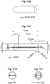
- Figs. 1A, 1B, 1C, and 1D show back, side, bottom, and front views respectively of a cover case 100 for a reusable tampon applicator, according to one embodiment of the present invention.
- cover case 100 is of a simple straight cylindrical shape, with a sealed flat surface 111 on a proximal end 110, and an open flat surface 131 with a base opening on a distal end 130.
- Barrel 120 is of a straight cylindrical shape and extends from proximal end 110 to distal end 130 to form cover case 100.
- cover case 100 When the tampon applicator is not in use, cover case 100 encloses other components of the tampon applicator, for hygienic and compact storage in a purse or a back pocket.
- Flat proximal and distal surfaces 111 and 131 allow cover case 100 to be stood up on either end, for easy placement on a counter-top, and for quick drying after a water rinse.
- proximal surface 111 and distal surface 131 may be curved or shaped differently, and barrel 120 may be further contoured or curved.
- a bottom view as shown in Fig. 1C reveals a circular base opening in this particular illustrative example.
- cross-sections of cover case 100 along different locations of barrel 120 may vary in shape.
- Cover case 100 may be made of flexible or rigid materials, and may comprise one or more materials such as silicone, plastics, metal, and fabrics.
- Figs. 2A, 2B, 2C, 2D, and 2E show back, side, bottom, sectional and front views respectively of a body 200 for a reusable tampon applicator, according to one embodiment of the present invention.
- body 200 is of a cylindrical shape, comprising a convex apex 215 on a proximal end 210, a hollow barrel portion 220, a transition portion 225, and a base grip portion 235 on a distal end 230.
- transition portion 225 and base grip 235 are optional and excluded.
- base grip 235 may have an external diameter larger than that of barrel 220, while curved transition portion 225 may taper to smoothly transit base grip 235 towards barrel portion 220.
- Such a design allows hygienic handling of the tampon applicator during use, as it enables a user to hold cylindrical body 200 at base grip 235 firmly without touching barrel 220, which in turn comes into contact with internal tissues during use.
- barrel 220 is of a straight cylindrical shape in this example, it may include a convex bulge or a concave narrowing in its upper, middle, or lower section in some other embodiments.
- convex apex 215 is shown as rounded or spherical in Figs. 2A, 2B, and 2E , in some other embodiments of the present invention, convex apex 215 may be acute, obtuse, or of any other convex shape that may facilitate easy insertion into a user's vagina during tampon application.
- a single slit opening 205 as shown in Fig. 2A cuts apex 215 into two separate pieces or "petals" 204, which may bend to allow a tampon to pass through slit opening 205 during tampon application.
- slit opening 205 may extend along barrel 220 laterally, down from proximal end 210 towards distal end 230 to form a partial slit 260 as shown in Fig. 2A , and from proximal end 210 to distal end 230 to form a full slit 270, as shown in Fig. 2E .
- partial slit 260 cuts only a few millimeters into barrel 220, past convex apex 215.
- partial slit 260 may cut 2mm to 5mm, 5mm to 7mm, or 7mm to 10mm into barrel 220, past convex apex 215.
- partial slit 260 may cut or extend through up to half of a lateral length of straight barrel 220. In yet some other embodiments, partial slit 260 may cut or extend through almost all of the lateral length of barrel 220. The partial slit is shorter in length along the cylindrical body than the full slit. In some other embodiments not shown here, more than one slits may intersect at the convex apex to form more than two petals, making the convex apex resemble a floret that can easily open during tampon application. Each slit opening may cut into the straight barrel portion at different depths. Moreover, as shown in Fig.
- a flat distal surface 231 on distal end 230 allows cylindrical body 200 to be stood up straight, for easy upright placement on a counter-top, and quick water drainage and drying after cleaning.
- distal surface 231 may be contoured or curved differently, with or without flat portions for upright placements.
- partial slit 260 as shown in Figs. 2A and 2E allows slit opening 205 to open wide enough for a tampon to pass through in an intended straight direction during use, without forcing the tampon towards or out of open full slit 270 on the opposite side.
- Full slit 270 as shown in Fig. 2E allows the insertion of a brush or a finger for thorough cleaning of the inside of cylindrical body 200 after each use.
- Full slit 270 also allows a tampon string to pass through during tampon application, thus minimizing the probability of accidentally catching or latching the tampon string in the applicator, or leaving the tampon string in a crushed or tangled state, which may make the tampon string difficult to catch after tampon use.
- curved corners 280 where full slit 270 and flat distal surface 231 join is contoured to maximize user safety and comfort. Similar curvatures may be further included in other corners, edges, rims, ridges, or similar features of the tampon applicator.
- Figs. 11A to 13E provide an illustrative embodiment where individual curvatures are respectively labeled.
- Fig. 2C shows a bottom view of cylindrical body 200.
- a partial ring-shaped protrusion 243 is formed along the internal circumference of cylindrical body 200 at an appropriate lateral position. Partial ring-shaped protrusion 243 interfaces with a latch or notch 323 on a pusher 300 to tightly secure cylindrical body 200 and pusher 300 when not in use, as discussed with respect to Figs. 3A .
- Such a partial ring-shaped protrusion may be optional and excluded in some other embodiments not explicitly shown here.
- Fig. 2D shows a sectional view of cylindrical body obtained along corresponding cutting planes A-A in Fig. 2B .
- cylindrical body 200 comprises an outer layer 250 and an inner support layer 255.
- Inner support layer 255 is shown to be completely flush to outer layer 250.
- a smooth inner surface of cylindrical body 200 thus obtained allows a tampon to glide through easily.
- the inner and outer layers may be mechanically attached or bounded through a co-molding process such as co-injection molding or bi-injection molding.
- Outer layer 250 may fully extend over the entire exterior surface of cylindrical body 200, including barrel 220, convex apex 215, and optional transition portion 225 and grip portion 235.
- Partial slit 260 and full slit 270 as displayed in Fig. 2E are cut into outer layer 250.
- outer layer 250 is made of a flexible biocompatible material such as medical-grade or food-grade silicone to reduce possible allergic reactions or immune responses when cylindrical body 200 comes into contact with internal tissues during use.
- outer layer 250 is made of a hydrophobic or water-repellent material, or coated with such a layer, so blood or other body fluids are less likely to accumulate. Having a hydrophobic composition or coating also enables quick drying after a water rinse.
- outer layer 250 is made of a water-proof or water impermeable material.
- outer layer 250 may be made flexible enough so petals 204 as shown in Fig. 2A open up during tampon application to allow a tampon to pass through slit opening 205.
- flexible folds or flaps 251 as shown in Fig. 2D allow full slit 270 to open slightly for easy washing and cleaning.
- inner support layer 255 extends over an interior lateral surface of barrel 220. In the lateral direction, inner support layer 255 may cover the entirety or a portion of barrel 220. When optional transition portion 225 and base grip 235 as shown in Fig. 2A are present, inner support layer 255 as shown in Fig. 2D may extend fully or partially over the interior surface of these portions as well. Moreover, inner support layer 255 may open wider along full slit opening 270, as shown in Fig. 2D . This difference in slit opening widths forms folds or flaps 251.
- inner support layer 255 is completely flush to outer layer 250.
- the smooth inner surface of cylindrical body 200 allow a tampon to glide through easily.
- a portion or all of inner support layer 255 may be exposed and visible from the inner surface of cylindrical body 200, while being completely flush to outer layer 250.
- inner support layer 255 may be completely embedded within outer layer 250, where inner support layer 255 is invisible from the inner surface of cylindrical body 200. The absence of part-lines between inner support layer 255 and outer layer 250 may ensure no blood or bacteria may be caught in between to cause any sanitation or hygiene problems.
- inner support layer 255 is made of natural or synthetic, hard, rigid or semi-rigid materials such as polymers, metals, and/or ceramics.
- inner support layer 255 may be a plastic support made from polymeric materials such as Acrylonitrile butadiene styrene (ABS), Nylon, rubber, latex, and such.
- ABS Acrylonitrile butadiene styrene
- Nylon Nylon
- rubber latex
- inner support layer 255 may be patterned to include one or more additional lateral, helical, or rotational slits or cuts, so a cross-sectional view of cylindrical body 200 resembles a cut-open internal "gear" where the teeth are formed on the inner surface.
- the "gear" teeth may be parallel to or at an angle to the lateral axis of cylindrical body 200, similar to a spur gear, a helical gear, a worm gear, or such.
- a patterned inner support layer 255 as described may enhance the flexibility of cylindrical body 200 without significantly impacting its rigidity.
- inner layer 255 may fully "unroll" cylindrical body 200 for thorough scrubbing and cleaning, while inner layer 255 still provides sufficient structural support for tampon insertion during use.
- a patterned inner support layer 255 may also serve as a movement guide for the tampon being applied.
- slits or cuts within inner support layer 255 may be filled or injected with the same material as outer layer 250, so inner support layer 255 is either flush to outer layer 250 on the inner surface of cylindrical body 200, or completely embedded within outer layer 250.
- Figs. 3A, 3B, 3C, and 3D show back, side, bottom, and front views of a pusher 300 for a reusable tampon applicator respectively, according to one embodiment of the present invention.
- pusher 300 as shown in Fig. 3A comprises a cylindrical straight barrel portion 320 extending from a proximal end 310 to a distal end 330.
- pusher 300 further comprises one or more of a conical pyramid-shaped tip 315 at proximal end 310, a transition potion 325 at a distal end 330 of straight barrel 320, a step transition portion 326, and a base grip portion 335 at distal end 330.
- Conical pyramid-shaped tip 315 may comprise a flat proximal surface 311 for exerting force on a tampon during tampon application.
- base grip 335 may have an external diameter larger than or smaller than that of straight barrel 320 and step transition portion 326.
- step transition portion 326 may have a diameter larger than or smaller than that of straight barrel 320.
- transition portion 325 may taper appropriately to smoothly transit between the two portions. Transition portion 325, step transition portion 326, and base grip portion 335 may also be excluded entirely.
- Base grip portion 335 allows hygienic handling of the tampon applicator during use, as it enables a user to hold pusher 300 firmly without touching straight barrel 320, which comes into contact with the tampon and cylindrical body 200 during tampon application.
- a flat distal surface 331 of pusher 300 allows pusher 300 to be stood up straight, for easy upright placement on a counter-top, and quick water drainage and drying after cleaning.
- distal surface 331 may be contoured or curved differently, with or without flat portions for upright placement.
- bottom view as shown in Fig. 3C may be of square, rectangular, stellar, or any other shape.
- one or more bumps, latches or notches such as 323 and 327 shown in Fig. 3A may be present, for tightly securing pusher 300, cylindrical body 200, and/or case 100 when the tampon applicator is not in use. It would be understood by persons skilled in the art that the drawings are not necessarily drawn to scale, thus notches 323 and 327 may raise or bump above the lateral surface only minimally. In some embodiments, corresponding individual or ring-shaped depressions, dents, grooves or protrusions may be present on an internal surface of cylindrical body 200 and/or case 100 for interfacing or clicking onto the notches as shown.
- Such notches and/or depressions may be located symmetrically or asymmetrically around the internal lateral circumferences of straight barrel 220, internal lateral circumferences of case 100, or external lateral circumferences of straight barrel 320 and step transition portion 326.
- neither notches nor depressions may be present, and various internal and external diameters of case 100, body 200, and pusher 300 may be carefully designed so that a tight and secure assembly can be achieved.
- Figs. 4A and 4B show a back side view 400 and a front side view 450 of cylindrical body 200 respectively, according to one embodiment of the present invention.
- cylindrical body 200 comprises a convex apex 215 on a proximal end 210, a barrel portion 220, an optional tapered transition portion 225, and an optional base grip portion 235 on a distal end 230.
- Dotted line 415 in Fig. 4A represents an adjoining boundary between convex apex 215 and straight barrel 220.
- Slit opening 205 extends along straight barrel 220 laterally or longitudinally, down from proximal end 210 towards distal end 230 to form partial slit 260 shown in Fig. 4A , with a length 460, and from proximal end 210 to distal end 230 to form full slit 270 shown in Fig. 4B , with a length 470.
- the ratio of length 460 to length 470 is between 1:10 and 2:7, between 2:7 and 1:3, between 1:3 and 1:2, or between 1:2 and 19:20, either inclusively or exclusively.
- partial slit 260 does not cut into straight barrel 220.
- partial slit 260 cuts into straight barrel 220, and length 440 is between 2mm to 5mm, 5mm to 7mm, 7mm to 10mm, or is more than 10mm. Partial slit 260 is shorter in length than full slit 270.
- partial slit 260 and full slit 270 have the same uniform width 472.
- slit width may differ between partial slit 260 and full slit 270, and slit width 472 may vary along the lateral side of cylindrical body 200.
- slit width 472 may be larger towards the proximal end to facilitate easy tampon expulsion, or may be larger towards the distal end to make cleaning easier.
- straight barrel portion 220 from Fig. 4A is shown to have a uniform external diameter 420 in Fig. 4B .
- external diameter 420 may vary laterally along cylindrical body 200.
- barrel portion 220 may comprise a convex bulge in its upper, middle, or lower section, with a narrower convex apex 215 and/or a narrower base grip portion 235, or may comprise a concave narrowing in its upper, middle, or lower section, with a wider convex apex 215 and/or a wider base grip portion 235.
- Base grip portion 235 has an external diameter 490 in this illustration example.
- transition portion 225 with length 425 smoothly transits straight barrel portion 220 into base grip portion 235 with length 435.
- Each of lengths 425 and 435 may vary between zero and a third of length 470.
- An external base grip diameter 490 larger than an external barrel diameter 420 allows a user to hold cylindrical body 200 firmly without touching barrel portion 220.
- external base grip diameter 490 may be smaller than external barrel diameter 420, with transition portion 225 curving into instead of curving out to base grip portion 225. Such a design may help trap the tampon once disposed inside cylindrical body 200, thus avoiding accidentally dropping the tampon during tampon application.
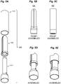
- Fig. 5A shows an exploded perspective view 500 of a reusable tampon applicator, having the case, the body, and the pusher shown in Figs. 1A , 2A , and 3A respectively, according to one embodiment of the present invention.
- Case 510, cylindrical body 520, and pusher 530 are as described with respect to Figs. 1A to 4B .
- Each of case 510, cylindrical body 520, and pusher 530 may be manufactured with an injection molding process.
- a co-molding process may also be employed to form or bound outer and inner layers of cylindrical body 520.
- case 510 and at least a segment of pusher 520 may be made of stamped metal, without injection molding.
- Fig. 5B shows a front view of an assembly 580 when pusher 530 is telescopically inserted into cylindrical body 520
- Fig. 5C shows another front view of an assembly 590 when case 510 encloses the assembly 580.
- Figs. 5D and 5E zoom into assembled views in Figs. 5B and 5C respectively around the distal end of the tampon applicator, showing optional notches for securing individual components together.
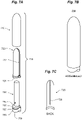
- Figs. 6A, 6B, 6C, and 6D illustrate the use of a reusable tampon applicator for disposing a tampon into the tampon applicator, and inserting the tampon into a user's body, according to one embodiment of the present invention. More specifically, Fig. 6A presents an assembled tampon applicator 610 ready for use or storage. After the cover case is removed, Fig. 6B illustrates a pulling action to remove the telescopically inserted pusher 630 from cylindrical body 620. Next, a tampon 640 as shown in Fig. 6C may be inserted by a user into cylindrical body 620, followed by pusher 630.
- Tampon string 645 maybe positioned along full slit 670 shown in Fig. 6D during this process.
- the assembled pusher-tampon-body may then be inserted into the vaginal opening, and force may be exerted through pusher 630 to expulse or eject tampon 640 through the slit opening on the proximal end of cylindrical body 620, as illustrated by Fig. 6D .
- "Petals" 604 and 606 formed by the slit opening open or bend outward to allow tampon 640 to pass through, and tampon string 645 may glide along full slit 670 in this process.
- Fig. 7A shows an exploded perspective view 700 of a reusable tampon applicator, according to a second embodiment of the present invention, with case 710, cylindrical body 720, and pusher 730.
- Fig. 7B shows a corresponding assembled view 750
- Fig. 7C shows a back view of cylindrical body 720.
- case 710 is flat on the distal end, but convexly curved on the proximal end. It would be clear to ones skilled in the art that case 710 may take on any shape as long as it is capable of enclosing the body and pusher portions of a reusable tampon applicator as disclosed.
- cylindrical body 720 as shown in Fig.
- Distal surface 721 of cylindrical body 720 is curved in this particular example.
- pusher 730 may contain a seat portion 755 with curved proximal surface 754 that locks with distal surface 721 of cylindrical body 720.
- Pusher 730 may further comprise decorative components such as surface line 757, while base grip 758 may comprise a curved distal surface 759.
- Fig. 8A shows an exploded perspective view 800 of a reusable tampon applicator, according to a third embodiment of the present invention, with case 810, cylindrical body 820, and pusher 830.
- Fig. 8B shows a corresponding assembled view 850.
- Figs. 8C and 8D show top views 825 and 835 of cylindrical body 820 and pusher 830 respectively.
- case 810 is slanted on the distal end, and convexly curved on the proximal end.
- Cylindrical body 820 comprises a full slit 827, and a partial slit on the opposite side.
- Pusher 830 may be hollow, with a proximal opening 831 through which a tampon string can be inserted or threaded. A full slit 837 on one side of pusher 830 also allows the tampon string to pass through. A circular rim 832 may serve as a tightening notch to secure pusher 830 and body 820 together when the tampon applicator is not in use. Furthermore, in this example, base grip 833 has a contoured distal surface 834.
- Fig. 9A shows an exploded perspective view 900 of a reusable tampon applicator, according to a fourth embodiment of the present invention, with case 910, cylindrical body 920, and pusher 930.
- Fig. 9B shows a corresponding assembled view 950.
- Figs. 9C and 9D show top views 925 and 935 of cylindrical body 920 and pusher 930 respectively.
- case 910 is flat on both the distal end and the proximal end, and has decagon-shaped cross-sections.
- cylindrical body 920 also has decagon-shaped cross-sections.
- case 910, cylindrical body 920, and pusher 930 may have cross-sections shaped as regular or non-regular polygons with any number of edges.
- cylindrical body 920 does not include any full lateral slits. Instead, more than one slit openings are cut on convex apex 922 to form a floret containing more than two petals. As shown in Fig. 9C , five petals including petal 928 are present in this particular example.
- Pusher 930 has a spoked cross-section, illustrated by Fig. 9D .
- slit openings on convex apex 922 may extend and cut into the barrel portion of body 920, at the same or different lengths or depths.
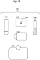
- Fig. 10 shows a THINX reusable tampon applicator hygiene pack 1000, according to one embodiment of the present invention. While a THINX reusable tampon applicator 1010 as described previously with references to Figs. 1A to 9D may be carried and used individually, it may also be combined with one or more other optional accessories such as biodegradable films 1040, biodegradable wipes 1050, a tampon 1060 with a built-in film, and a clutch or carrying purse 1070. A biodegradable film 1040 may be used to cover the entire tampon applicator body before tampon insertion, during which a tampon pushes through a perforation.
- biodegradable film 1040 may be used to cover the entire tampon applicator body before tampon insertion, during which a tampon pushes through a perforation.
- Biodegradable film 1040 may be disposable to provide a convenient and hygienic way of minimizing direct contact of the reusable tampon applicator with blood or other body fluids.
- a tampon 1060 with a build-in film may be made of organic cotton packed and wrapped with a hygienic, biocompatible film that extends beyond the body of the tampon, to offer additional hygienic protection by minimizing direct contact of the tampon with the inside surface of the cylindrical body of a reusable tampon applicator.
- Biodegradable wipe 1050 may be made of organic cotton and pre-moistened to provide a portable and disposable solution for cleaning and refreshing the user's hands or the reusable tampon applicator before and/or after a tampon change.
- clutch or carrying purse 1070 may be compartmentalized to store any of reusable tampon applicator 1010, biodegradable films 1040, biodegradable wipes 1050, and tampon 1060.
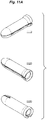
- Fig. 11A shows three perspective views 1110, 1120, and 1130 of an exemplary applicator body, according to one embodiment of the present invention. Following general engineering drawing protocols, part outlines and section lines are solid, while hidden lines are dotted. A full slit is visible in perspective views 1110 and 1120, while a partial slit is visible in perspective view 1130.
- Figs. 11B, 11C, 11D, 11E , 11F, 11G, 11H, and 11J show respective different side and sectional views of the exemplary applicator body in Fig. 11A , with illustrative dimensions where appropriate.
- Side views 1140 in Fig. 11B and 1160 in Fig. 11F , front view 1150 in Fig. 11C , bottom view 1154 in Fig. 11E , and back side view 1170 in Fig. 11H are similar to the ones shown in Figs. 2A, 2B, 2C, and 2E .
- Top view 1152 in Fig. 11D is obtained by looking down the convex apex of the cylindrical body, bottom view 1154 in Fig.
- FIG. 11E is obtained by looking up the distal base opening of the cylindrical body, while sectional views 1162 in Fig. 11G and 1172 in Fig. 11J are obtained along corresponding cutting planes A-A and B-B shown in Figs. 11F and 11H .
- the partial lateral slit exceeds the lateral length of the convex apex by 4mm, in a range between 2mm and 5mm.
- the partial lateral slit and full lateral slit has a ratio in length of 2:7 (20mm:70mm), in a range between 1:10 and 2:7 inclusive.
- the exemplary cylindrical body has a thickness of 0.79mm at the tip along the slit opening, and a thickness of 1.50mm along the length of the straight barrel portion.
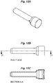
- Fig. 12A shows a perspective view of an exemplary pusher, according to one embodiment of the present invention.
- Figs. 12B, 12C , 12D, 12E, and 12F show respective side and sectional views of the exemplary pusher in Fig. 11A , with illustrative dimensions where appropriate.
- FIG. 13A shows a perspective view of an exemplary case, according to one embodiment of the present invention.
- Figs. 13B, 13C, 13D, and 13E show respective side and sectional views of the exemplary case in Fig. 13A , with illustrative dimensions where appropriate.
- Every embodiment may be unique, and constituting components may be either shortened or lengthened, narrowed or widened; methods and steps may also be shortened or lengthened, overlapped with other activities, postponed, delayed, and continued after a time gap, during the practice of the present invention.
Landscapes
- Health & Medical Sciences (AREA)
- Engineering & Computer Science (AREA)
- Vascular Medicine (AREA)
- Epidemiology (AREA)
- Biomedical Technology (AREA)
- Heart & Thoracic Surgery (AREA)
- Life Sciences & Earth Sciences (AREA)
- Animal Behavior & Ethology (AREA)
- General Health & Medical Sciences (AREA)
- Public Health (AREA)
- Veterinary Medicine (AREA)
- Manufacturing & Machinery (AREA)
- Absorbent Articles And Supports Therefor (AREA)
Claims (18)
- Applicateur de tampon réutilisable (1010), comprenant :un corps (200) pour contenir un tampon (1060) pour l'application de tampon (1060), le corps (200) comprenant une extrémité distale (230), une extrémité proximale (210), et une ouverture de base au niveau de l'extrémité distale (230) pour insérer le tampon (1060) dans un cylindre (220) raccordé à un sommet convexe (215) au niveau de l'extrémité proximale (210),dans lequel le sommet convexe (215) comprend une pluralité d'ouvertures en fente (205) pour former plus d'un pétale (204) pour que le tampon (1060) passe à travers durant l'application de tampon (1060), dans lequel une première ouverture en fente (205) s'étend le long d'une première partie du cylindre (220) latéralement à partir de l'extrémité proximale (210) jusqu'à l'extrémité distale (230) pour former une fente complète (270), dans lequel une seconde ouverture en fente (205) s'étend le long d'une seconde partie du cylindre (220) latéralement à partir d'une première ouverture en fente (205) au niveau de l'extrémité proximale (210) et partiellement en direction de l'extrémité distale (230) pour former une fente partielle (260), dans lequel le corps (200) comprend en outre des plis ou rabats (251) flexibles configurés pour permettre l'ouverture partielle de la fente complète (270) et de la fente partielle (260) ; etun dispositif de poussée (300), pour l'insertion télescopique dans le corps (200), et pour pousser le tampon (1060) hors des une ou plusieurs ouvertures en fente (205) durant l'application de tampon (1060).
- Applicateur de tampon réutilisable (1010) selon la revendication 1, comprenant en outre :
un étui (100) pour enfermer de manière télescopique le corps (200) et le dispositif de poussée (300). - Applicateur de tampon réutilisable (1010) selon la revendication 1, dans lequel le dispositif de poussée (300) comprend au moins une encoche (323) sur une surface latérale externe pour fixer le dispositif de poussée (300) et le corps (200) lorsqu'ils ne sont pas utilisés.
- Applicateur de tampon réutilisable (1010) selon la revendication 1, dans lequel le dispositif de poussée (300) comprend un bord circulaire (832) pour fixer le dispositif de poussée (300) et le corps (200) lorsqu'ils ne sont pas utilisés.
- Applicateur de tampon réutilisable (1010) selon la revendication 1, dans lequel le corps (200) comprend au moins un taquet ou une encoche pour fixer le corps (200) et le dispositif de poussée (300) lorsqu'ils ne sont pas utilisés.
- Applicateur de tampon réutilisable (1010) selon la revendication 1, dans lequel le corps (200) comprend :
une partie de préhension de base (235) au niveau de l'extrémité distale (230) du corps (200), dans lequel un diamètre externe de la partie de préhension de base (235) est plus grand qu'un diamètre externe du cylindre (220). - Applicateur de tampon réutilisable (1010) selon la revendication 1, dans lequel l'extrémité distale (230) du corps (200) comprend une surface de base plate, la surface de base plate pour faire tenir le corps (200) debout sur une surface plate.
- Applicateur de tampon réutilisable (1010) selon la revendication 1, dans lequel une extrémité distale (330) du dispositif de poussée (300) comprend une surface de base plate, la surface de base plate pour faire tenir le dispositif de poussée (300) debout sur une surface plate.
- Applicateur de tampon réutilisable (1010) selon la revendication 1, dans lequel le dispositif de poussée (300) comprend :une partie proximale (310), une partie de préhension de base (335) au niveau d'une extrémité distale (330) du dispositif de poussée (300),dans lequel un diamètre externe de la partie proximale (310) est inférieur à un diamètre interne de l'ouverture de base du corps (200), etdans lequel un diamètre externe de la partie de préhension de base (335) du dispositif de poussée (300) est plus grand que le diamètre interne de l'ouverture de base du corps (200).
- Applicateur de tampon réutilisable (1010) selon la revendication 1, dans lequel le dispositif de poussée (300) est en outre scellé au niveau d'une extrémité distale (330) du dispositif de poussée (300).
- Applicateur de tampon réutilisable (1010) selon la revendication 1, dans lequel au moins une parmi les ouvertures en fente (205) sur le sommet convexe (215) s'étend dans le cylindre (220) pour former une fente latérale partielle.
- Applicateur de tampon réutilisable (1010) selon la revendication 11, dans lequel la fente latérale partielle dépasse la longueur latérale du sommet convexe (215) d'une valeur comprise entre 2 mm et 5 mm.
- Applicateur de tampon réutilisable (1010) selon la revendication 11, dans lequel la fente latérale partielle et le corps (200) ont un rapport de longueur latérale compris entre 1/10 et 2/7, inclus.
- Emballage hygiénique (1000) d'applicateur de tampon réutilisable, comprenant :l'applicateur de tampon réutilisable (1010) selon l'une quelconque des revendications 1 à 13 ; etun sac de transport (1070) pour stocker l'applicateur de tampon réutilisable (1010).
- Emballage hygiénique (1000) d'applicateur de tampon réutilisable selon la revendication 14, comprenant en outre un tampon (1060) avec un film intégré.
- Procédé de fabrication d'un applicateur de tampon réutilisable (1010), comprenant les étapes de :formation d'un corps (200), le corps (200) comprenant une extrémité distale (230) et une extrémité proximale (210),dans lequel l'extrémité distale (230) comprend une ouverture de base pour insérer un tampon (1060) dans un cylindre (220) raccordé à un sommet convexe (215) au niveau de l'extrémité proximale (210),dans lequel le sommet convexe (215) comprend une pluralité d'ouvertures en fente (205) pour former plus d'un pétale (204) pour que le tampon (1060) passe à travers durant l'application de tampon (1060), dans lequel une première ouverture en fente (205) s'étend le long du cylindre (220) latéralement à partir de l'extrémité proximale (210) jusqu'à l'extrémité distale (230) pour former une fente complète (270), dans lequel une seconde ouverture en fente (205) s'étend le long d'une seconde partie du cylindre (220) latéralement à partir de la première ouverture en fente (205) au niveau de l'extrémité proximale (210) et partiellement en direction de l'extrémité distale (230) pour former une fente partielle (260), dans lequel le corps (200) comprend en outre des plis ou rabats (251) flexibles configurés pour permettre l'ouverture partielle de la fente complète (270) et de la fente partielle (260) ; etla formation d'un dispositif de poussée (300), pour l'insertion télescopique dans le corps (200), et pour pousser le tampon (1060) hors des une ou plusieurs ouvertures en fente (205) durant l'application de tampon (1060).
- Procédé selon la revendication 16, dans lequel la formation du corps (200) comprend la délimitation d'une couche de support interne en plastique et d'une couche externe en silicone de qualité médicale ou de qualité alimentaire.
- Procédé selon la revendication 16, dans lequel le dispositif de poussée (300) est en outre scellé au niveau d'une extrémité distale (330) du dispositif de poussée (300).
Applications Claiming Priority (3)
| Application Number | Priority Date | Filing Date | Title |
|---|---|---|---|
| US201562195295P | 2015-07-22 | 2015-07-22 | |
| US15/184,512 US9532907B1 (en) | 2015-07-22 | 2016-06-16 | Reusable tampon applicators, methods of manufacture, and methods of use |
| PCT/US2016/043253 WO2017015426A1 (fr) | 2015-07-22 | 2016-07-21 | Applicateurs de tampon réutilisables, procédés de fabrication et procédés d'utilisation |
Publications (3)
| Publication Number | Publication Date |
|---|---|
| EP3324909A1 EP3324909A1 (fr) | 2018-05-30 |
| EP3324909A4 EP3324909A4 (fr) | 2018-12-19 |
| EP3324909B1 true EP3324909B1 (fr) | 2022-03-30 |
Family
ID=57682271
Family Applications (1)
| Application Number | Title | Priority Date | Filing Date |
|---|---|---|---|
| EP16828515.3A Active EP3324909B1 (fr) | 2015-07-22 | 2016-07-21 | Applicateurs de tampon réutilisables, procédés de fabrication et procédés d'utilisation |
Country Status (8)
| Country | Link |
|---|---|
| US (2) | US9532907B1 (fr) |
| EP (1) | EP3324909B1 (fr) |
| JP (1) | JP6228715B1 (fr) |
| KR (1) | KR20180031695A (fr) |
| CN (2) | CN108670560A (fr) |
| AU (1) | AU2016297013B2 (fr) |
| CA (1) | CA2966514C (fr) |
| WO (1) | WO2017015426A1 (fr) |
Families Citing this family (18)
| Publication number | Priority date | Publication date | Assignee | Title |
|---|---|---|---|---|
| WO2014004560A1 (fr) | 2012-06-25 | 2014-01-03 | Playtex Products, Llc | Ensemble emballage pour ou comprenant un applicateur de tampon |
| WO2017223500A1 (fr) * | 2016-06-24 | 2017-12-28 | Edgewell Personal Care Brands, Llc | Emballage pour applicateurs de tampons. |
| WO2018018046A1 (fr) | 2016-07-22 | 2018-01-25 | Edgewell Personal Care Brands, Llc | Applicateur de tampon à extrémité d'insertion améliorée |
| WO2018140192A1 (fr) * | 2017-01-24 | 2018-08-02 | Liv Labs Inc. | Dispositif pour incontinence urinaire à l'effort (iue) |
| US11191677B2 (en) * | 2018-05-18 | 2021-12-07 | Tina Holdings, Llc | Tampon insertion device |
| ES1217271Y (es) * | 2018-07-24 | 2018-12-05 | Font Caselles Ramon | Aplicador de tampones |
| AU2020275000B2 (en) * | 2019-05-14 | 2025-07-10 | Obstetrx, Inc. | Post-partum hemorrhage treatment device |
| US11324643B1 (en) * | 2019-07-01 | 2022-05-10 | Jessica Samson | Reusable tampon applicator |
| USD901684S1 (en) * | 2019-07-24 | 2020-11-10 | Rinovum Subsidiary 2, LLC | Reusable incontinence device applicator |
| WO2021031162A1 (fr) * | 2019-08-21 | 2021-02-25 | 吴静茹 | Tampon de type cathéter, ensemble de cathéters télescopiques et doigtier de tampon |
| CN112402107A (zh) * | 2019-08-21 | 2021-02-26 | 吴静茹 | 导管式卫生棉条及其伸缩导管组及卫生棉条指套 |
| WO2021120123A1 (fr) * | 2019-12-19 | 2021-06-24 | 吴静茹 | Procédé de fabrication d'un tampon type traction |
| CN112998961A (zh) * | 2019-12-19 | 2021-06-22 | 吴静茹 | 牵动式卫生棉条的制造方法 |
| CO2020006998A1 (es) | 2020-06-08 | 2021-12-10 | Productos Familia Sa | Aplicador reutilizable de tampón |
| SI26117B (sl) * | 2020-12-09 | 2026-01-30 | Tosama Tovarna Sanitetnega Materiala D.O.O. | Večkratno uporabljiv aplikator za vstavljanje higienskega tampona |
| KR102520507B1 (ko) * | 2021-03-30 | 2023-04-10 | 장소피아미정 | 친환경 탐폰 어플리케이터 및 이의 제조방법 |
| USD1071181S1 (en) | 2022-04-20 | 2025-04-15 | Liv Labs Inc. | Urinary incontinence device |
| CN115350002B (zh) * | 2022-10-09 | 2022-12-27 | 兴晔新材料(南通)有限公司 | 一种环保型卫生棉条套装及其使用方法 |
Citations (1)
| Publication number | Priority date | Publication date | Assignee | Title |
|---|---|---|---|---|
| USD719653S1 (en) * | 2014-08-10 | 2014-12-16 | Thinx, LLC | Reusable tampon applicator |
Family Cites Families (55)
| Publication number | Priority date | Publication date | Assignee | Title |
|---|---|---|---|---|
| US2733714A (en) * | 1956-02-07 | |||
| US940519A (en) * | 1908-10-17 | 1909-11-16 | Eugene H Eastman | Surgical applicator. |
| US2351836A (en) * | 1938-10-18 | 1944-06-20 | Popper Otto | Vaginal pack device |
| GB744209A (en) | 1953-08-17 | 1956-02-01 | Yervant Hosrof Kurkjian | Improvements relating to tampon introducers |
| US3204635A (en) * | 1963-03-21 | 1965-09-07 | Voss | Hygienic devices |
| US3674026A (en) | 1970-12-28 | 1972-07-04 | Kimberly Clark Co | Tampon insertion device |
| US3895634A (en) | 1973-10-18 | 1975-07-22 | Rapid American Corp | Tampon inserter |
| USD250663S (en) | 1977-04-25 | 1978-12-26 | The Procter & Gamble Company | Tampon inserter |
| US4159719A (en) * | 1977-05-09 | 1979-07-03 | Xomed, Inc. | Moisture-expandable ear wick |
| USD250049S (en) | 1977-08-05 | 1978-10-24 | The Procter & Gamble Company | Outer tube for a tampon inserter |
| US4148317A (en) | 1977-09-14 | 1979-04-10 | Personal Products Company | Reduced length tampon-applicator assembly |
| JPS5921786Y2 (ja) * | 1979-02-07 | 1984-06-28 | 株式会社吉野工業所 | 女性用吸湿剤入り容器 |
| JPS5925375Y2 (ja) * | 1979-02-23 | 1984-07-25 | 株式会社吉野工業所 | タンポン插入具 |
| US4699610A (en) | 1984-11-29 | 1987-10-13 | Lion Corporation | Catamenial tampon inserter |
| JPS6233826U (fr) * | 1985-08-12 | 1987-02-27 | ||
| US4650459A (en) | 1985-10-21 | 1987-03-17 | Kimberly-Clark Corporation | Convolutely wound paper tampon tube |
| GB8711486D0 (en) | 1987-05-15 | 1987-06-17 | Smith & Nephew Ass | Tampon applicators |
| US4895559A (en) * | 1987-08-04 | 1990-01-23 | Shippert Ronald D | Nasal pack syringe |
| JPH0225227U (fr) * | 1988-08-05 | 1990-02-20 | ||
| DE3910458C1 (en) * | 1989-03-31 | 1990-09-20 | Johnson & Johnson Gmbh, 4000 Duesseldorf, De | Tampon applicator |
| US5988386A (en) | 1998-03-20 | 1999-11-23 | Morrow; Jacqueline M. | Feminine hygiene storage unit |
| USD432784S (en) | 1998-04-24 | 2000-10-31 | Optoplast Plc | Tampon holder |
| USD427424S (en) | 1998-04-24 | 2000-07-04 | Optoplast Plc | Tampon holder |
| USD415565S (en) | 1999-01-04 | 1999-10-19 | The Procter & Gamble Company | Tampon applicator |
| WO2001030291A1 (fr) * | 1999-09-17 | 2001-05-03 | The Procter & Gamble Company | Dispositif d'insertion de tampon |
| AU7371500A (en) | 1999-09-17 | 2001-04-17 | Procter & Gamble Company, The | Tampon insertion device |
| US6450986B1 (en) * | 2000-06-19 | 2002-09-17 | Mcneil-Ppc, Inc. | Tampon applicator having outwardly flared rim |
| USD477075S1 (en) | 2001-09-26 | 2003-07-08 | Johnson & Johnson Gmbh | Tampon with compressed grooves |
| US6508780B1 (en) * | 2002-01-04 | 2003-01-21 | Playtex Products, Inc. | Laterally loaded insertion device |
| US6786883B2 (en) * | 2002-04-15 | 2004-09-07 | Ronald D. Shippert | Applicator for insertion of cargo into a body cavity |
| WO2004000160A2 (fr) * | 2002-06-21 | 2003-12-31 | Playtex Products, Inc. | Applicateur de tampon conique |
| US7727208B2 (en) * | 2002-09-12 | 2010-06-01 | Playtex Products, Inc. | Ergonomic tampon applicator |
| USD484681S1 (en) | 2002-12-26 | 2004-01-06 | Radius Corporation | Large tampon case |
| US7044928B2 (en) | 2003-04-04 | 2006-05-16 | Platex Products, Inc. | Tampon applicator assembly having an improved plunger and methods of making |
| USD492033S1 (en) | 2003-04-04 | 2004-06-22 | Playtex Products, Inc. | Tampon applicator assembly |
| US9192522B2 (en) * | 2003-05-02 | 2015-11-24 | Eveready Battery Company, Inc. | Tampon assembly having shaped pledget |
| ES2309404T3 (es) | 2004-02-05 | 2008-12-16 | THE PROCTER & GAMBLE COMPANY | Tampon con ranuras desplazadas. |
| US7137995B2 (en) * | 2004-03-01 | 2006-11-21 | Jsm Licensing, Llc. | Breast implant injector and method of use |
| USD517210S1 (en) | 2004-03-11 | 2006-03-14 | Playtex Products, Inc. | Tampon applicator plunger |
| USD516716S1 (en) | 2004-03-11 | 2006-03-07 | Playtex Products, Inc. | Tampon applicator plunger |
| USD615202S1 (en) | 2006-06-23 | 2010-05-04 | Playtex Products, Inc. | Tampon applicator with finger grip |
| USD602587S1 (en) | 2006-06-23 | 2009-10-20 | Playtex Products, Inc. | Tampon applicator with finger grip |
| USD568995S1 (en) | 2007-05-10 | 2008-05-13 | The Procter & Gamble Company | Tampon applicator |
| US20110275977A1 (en) * | 2008-08-29 | 2011-11-10 | Hitoshi Watanabe | Applicator for tampon |
| US20100193386A1 (en) * | 2009-01-30 | 2010-08-05 | Adrienne Rae Loyd | Vaginal-Health Products Comprising Colored Applicators |
| US20110040234A1 (en) | 2009-08-14 | 2011-02-17 | Bernard Chaffringeon | Dilator and tampon applicator device |
| USD619478S1 (en) | 2009-12-04 | 2010-07-13 | Playtex Products, Inc. | Tampon wrapper |
| CA2823792C (fr) * | 2011-01-07 | 2020-06-23 | John Mikhail | Applicateur de tampon hygienique hydrosoluble et biodegradable et procede et appareil pour sa fabrication |
| WO2014004560A1 (fr) * | 2012-06-25 | 2014-01-03 | Playtex Products, Llc | Ensemble emballage pour ou comprenant un applicateur de tampon |
| US9211216B2 (en) * | 2012-06-29 | 2015-12-15 | Kimberly-Clark Worldwide, Inc. | Tampon method of manufacture |
| USD716020S1 (en) | 2013-08-02 | 2014-10-28 | Thinx, LLC | Undergarment |
| CN203852487U (zh) * | 2014-05-13 | 2014-10-01 | 莎容企业有限公司 | 携带式小体积导管式卫生棉条 |
| US9615977B2 (en) * | 2014-06-06 | 2017-04-11 | Triple L Holdings, Inc. | Sanitary device |
| USD717950S1 (en) | 2014-08-10 | 2014-11-18 | Thinx, LLC | Reusable tampon applicator |
| USD741479S1 (en) | 2015-08-10 | 2015-10-20 | Thinx, Inc. | Reusable tampon applicator |
-
2016
- 2016-06-16 US US15/184,512 patent/US9532907B1/en active Active
- 2016-07-21 CA CA2966514A patent/CA2966514C/fr active Active
- 2016-07-21 AU AU2016297013A patent/AU2016297013B2/en active Active
- 2016-07-21 WO PCT/US2016/043253 patent/WO2017015426A1/fr not_active Ceased
- 2016-07-21 US US15/744,902 patent/US10993846B2/en active Active
- 2016-07-21 EP EP16828515.3A patent/EP3324909B1/fr active Active
- 2016-07-21 KR KR1020187003571A patent/KR20180031695A/ko not_active Withdrawn
- 2016-07-21 CN CN201810587100.7A patent/CN108670560A/zh active Pending
- 2016-07-21 JP JP2017523892A patent/JP6228715B1/ja active Active
- 2016-07-21 CN CN201680003461.1A patent/CN107106354B/zh active Active
Patent Citations (1)
| Publication number | Priority date | Publication date | Assignee | Title |
|---|---|---|---|---|
| USD719653S1 (en) * | 2014-08-10 | 2014-12-16 | Thinx, LLC | Reusable tampon applicator |
Also Published As
| Publication number | Publication date |
|---|---|
| EP3324909A1 (fr) | 2018-05-30 |
| AU2016297013B2 (en) | 2017-06-22 |
| AU2016297013A1 (en) | 2017-05-18 |
| KR20180031695A (ko) | 2018-03-28 |
| CN107106354B (zh) | 2018-06-29 |
| US20180207037A1 (en) | 2018-07-26 |
| CA2966514A1 (fr) | 2017-01-26 |
| EP3324909A4 (fr) | 2018-12-19 |
| CA2966514C (fr) | 2018-03-20 |
| US20170020744A1 (en) | 2017-01-26 |
| CN107106354A (zh) | 2017-08-29 |
| HK1251439A1 (en) | 2019-02-01 |
| JP6228715B1 (ja) | 2017-11-08 |
| US9532907B1 (en) | 2017-01-03 |
| CN108670560A (zh) | 2018-10-19 |
| WO2017015426A1 (fr) | 2017-01-26 |
| US10993846B2 (en) | 2021-05-04 |
| JP2017536883A (ja) | 2017-12-14 |
Similar Documents
| Publication | Publication Date | Title |
|---|---|---|
| EP3324909B1 (fr) | Applicateurs de tampon réutilisables, procédés de fabrication et procédés d'utilisation | |
| US9498383B2 (en) | Swab applicator and methods of use | |
| US10575999B2 (en) | Package assembly for or with a tampon applicator | |
| US10080469B2 (en) | Bathing towel | |
| US20160361203A1 (en) | System and Method for Removal of Earwax and Particulates | |
| KR20210042630A (ko) | 생리컵과 생리컵 삽입 어플리케이터 | |
| WO2018048398A1 (fr) | Système et procédé d'élimination de cérumen et de particules | |
| US20240216178A1 (en) | Ear Hygienic Implements and Kit | |
| WO2017027302A1 (fr) | Dispositif d'hygiène personnelle | |
| KR101492256B1 (ko) | 스틱 일체형 화장품 용기 | |
| HK1251439B (en) | Reusable tampon applicators, methods of manufacture, and methods of use | |
| US20220280140A1 (en) | Personal hygiene swabs | |
| US20140182073A1 (en) | Fully Disposable Toilet Bowl Brush | |
| KR20070000185U (ko) | 캡슐형 일회용 칫솔 | |
| JP2017127655A (ja) | 口腔ケア具 | |
| US20080015484A1 (en) | Apparatus and method for cleaning and disinfecting body piercings | |
| KR200460278Y1 (ko) | 이어 클리너 | |
| CN213324453U (zh) | 吸管收纳盒 | |
| JP7459790B2 (ja) | 拭き取りチップ | |
| JP4580032B2 (ja) | 女性用エチケット用品 | |
| KR20250093564A (ko) | 귀 청소기 | |
| US20170079452A1 (en) | Covering attachments for chopsticks | |
| KR20180002441A (ko) | 스파츌라 수납구 | |
| SE2150348A1 (en) | A menstrual Cup | |
| FR3060973A1 (fr) | Ustensile a main pour le massage manuel du visage comportant une combinaison de corps massant |
Legal Events
| Date | Code | Title | Description |
|---|---|---|---|
| STAA | Information on the status of an ep patent application or granted ep patent |
Free format text: STATUS: THE INTERNATIONAL PUBLICATION HAS BEEN MADE |
|
| PUAI | Public reference made under article 153(3) epc to a published international application that has entered the european phase |
Free format text: ORIGINAL CODE: 0009012 |
|
| STAA | Information on the status of an ep patent application or granted ep patent |
Free format text: STATUS: REQUEST FOR EXAMINATION WAS MADE |
|
| 17P | Request for examination filed |
Effective date: 20170501 |
|
| AK | Designated contracting states |
Kind code of ref document: A1 Designated state(s): AL AT BE BG CH CY CZ DE DK EE ES FI FR GB GR HR HU IE IS IT LI LT LU LV MC MK MT NL NO PL PT RO RS SE SI SK SM TR |
|
| AX | Request for extension of the european patent |
Extension state: BA ME |
|
| DAV | Request for validation of the european patent (deleted) | ||
| DAX | Request for extension of the european patent (deleted) | ||
| A4 | Supplementary search report drawn up and despatched |
Effective date: 20181120 |
|
| RIC1 | Information provided on ipc code assigned before grant |
Ipc: A61F 13/30 20060101ALI20181114BHEP Ipc: A61F 13/20 20060101AFI20181114BHEP Ipc: A61F 13/32 20060101ALI20181114BHEP Ipc: A61F 13/26 20060101ALI20181114BHEP |
|
| REG | Reference to a national code |
Ref country code: HK Ref legal event code: DE Ref document number: 1251439 Country of ref document: HK |
|
| STAA | Information on the status of an ep patent application or granted ep patent |
Free format text: STATUS: EXAMINATION IS IN PROGRESS |
|
| 17Q | First examination report despatched |
Effective date: 20190705 |
|
| TPAC | Observations filed by third parties |
Free format text: ORIGINAL CODE: EPIDOSNTIPA |
|
| TPAC | Observations filed by third parties |
Free format text: ORIGINAL CODE: EPIDOSNTIPA |
|
| GRAP | Despatch of communication of intention to grant a patent |
Free format text: ORIGINAL CODE: EPIDOSNIGR1 |
|
| STAA | Information on the status of an ep patent application or granted ep patent |
Free format text: STATUS: GRANT OF PATENT IS INTENDED |
|
| INTG | Intention to grant announced |
Effective date: 20211102 |
|
| GRAS | Grant fee paid |
Free format text: ORIGINAL CODE: EPIDOSNIGR3 |
|
| GRAA | (expected) grant |
Free format text: ORIGINAL CODE: 0009210 |
|
| STAA | Information on the status of an ep patent application or granted ep patent |
Free format text: STATUS: THE PATENT HAS BEEN GRANTED |
|
| AK | Designated contracting states |
Kind code of ref document: B1 Designated state(s): AL AT BE BG CH CY CZ DE DK EE ES FI FR GB GR HR HU IE IS IT LI LT LU LV MC MK MT NL NO PL PT RO RS SE SI SK SM TR |
|
| REG | Reference to a national code |
Ref country code: GB Ref legal event code: FG4D |
|
| REG | Reference to a national code |
Ref country code: CH Ref legal event code: EP |
|
| REG | Reference to a national code |
Ref country code: AT Ref legal event code: REF Ref document number: 1478524 Country of ref document: AT Kind code of ref document: T Effective date: 20220415 |
|
| REG | Reference to a national code |
Ref country code: DE Ref legal event code: R096 Ref document number: 602016070576 Country of ref document: DE |
|
| REG | Reference to a national code |
Ref country code: IE Ref legal event code: FG4D |
|
| REG | Reference to a national code |
Ref country code: NL Ref legal event code: FP |
|
| REG | Reference to a national code |
Ref country code: LT Ref legal event code: MG9D |
|
| PG25 | Lapsed in a contracting state [announced via postgrant information from national office to epo] |
Ref country code: SE Free format text: LAPSE BECAUSE OF FAILURE TO SUBMIT A TRANSLATION OF THE DESCRIPTION OR TO PAY THE FEE WITHIN THE PRESCRIBED TIME-LIMIT Effective date: 20220330 Ref country code: RS Free format text: LAPSE BECAUSE OF FAILURE TO SUBMIT A TRANSLATION OF THE DESCRIPTION OR TO PAY THE FEE WITHIN THE PRESCRIBED TIME-LIMIT Effective date: 20220330 Ref country code: NO Free format text: LAPSE BECAUSE OF FAILURE TO SUBMIT A TRANSLATION OF THE DESCRIPTION OR TO PAY THE FEE WITHIN THE PRESCRIBED TIME-LIMIT Effective date: 20220630 Ref country code: LT Free format text: LAPSE BECAUSE OF FAILURE TO SUBMIT A TRANSLATION OF THE DESCRIPTION OR TO PAY THE FEE WITHIN THE PRESCRIBED TIME-LIMIT Effective date: 20220330 Ref country code: HR Free format text: LAPSE BECAUSE OF FAILURE TO SUBMIT A TRANSLATION OF THE DESCRIPTION OR TO PAY THE FEE WITHIN THE PRESCRIBED TIME-LIMIT Effective date: 20220330 Ref country code: BG Free format text: LAPSE BECAUSE OF FAILURE TO SUBMIT A TRANSLATION OF THE DESCRIPTION OR TO PAY THE FEE WITHIN THE PRESCRIBED TIME-LIMIT Effective date: 20220630 |
|
| REG | Reference to a national code |
Ref country code: AT Ref legal event code: MK05 Ref document number: 1478524 Country of ref document: AT Kind code of ref document: T Effective date: 20220330 |
|
| PG25 | Lapsed in a contracting state [announced via postgrant information from national office to epo] |
Ref country code: LV Free format text: LAPSE BECAUSE OF FAILURE TO SUBMIT A TRANSLATION OF THE DESCRIPTION OR TO PAY THE FEE WITHIN THE PRESCRIBED TIME-LIMIT Effective date: 20220330 Ref country code: GR Free format text: LAPSE BECAUSE OF FAILURE TO SUBMIT A TRANSLATION OF THE DESCRIPTION OR TO PAY THE FEE WITHIN THE PRESCRIBED TIME-LIMIT Effective date: 20220701 Ref country code: FI Free format text: LAPSE BECAUSE OF FAILURE TO SUBMIT A TRANSLATION OF THE DESCRIPTION OR TO PAY THE FEE WITHIN THE PRESCRIBED TIME-LIMIT Effective date: 20220330 |
|
| PG25 | Lapsed in a contracting state [announced via postgrant information from national office to epo] |
Ref country code: SM Free format text: LAPSE BECAUSE OF FAILURE TO SUBMIT A TRANSLATION OF THE DESCRIPTION OR TO PAY THE FEE WITHIN THE PRESCRIBED TIME-LIMIT Effective date: 20220330 Ref country code: SK Free format text: LAPSE BECAUSE OF FAILURE TO SUBMIT A TRANSLATION OF THE DESCRIPTION OR TO PAY THE FEE WITHIN THE PRESCRIBED TIME-LIMIT Effective date: 20220330 Ref country code: RO Free format text: LAPSE BECAUSE OF FAILURE TO SUBMIT A TRANSLATION OF THE DESCRIPTION OR TO PAY THE FEE WITHIN THE PRESCRIBED TIME-LIMIT Effective date: 20220330 Ref country code: PT Free format text: LAPSE BECAUSE OF FAILURE TO SUBMIT A TRANSLATION OF THE DESCRIPTION OR TO PAY THE FEE WITHIN THE PRESCRIBED TIME-LIMIT Effective date: 20220801 Ref country code: ES Free format text: LAPSE BECAUSE OF FAILURE TO SUBMIT A TRANSLATION OF THE DESCRIPTION OR TO PAY THE FEE WITHIN THE PRESCRIBED TIME-LIMIT Effective date: 20220330 Ref country code: EE Free format text: LAPSE BECAUSE OF FAILURE TO SUBMIT A TRANSLATION OF THE DESCRIPTION OR TO PAY THE FEE WITHIN THE PRESCRIBED TIME-LIMIT Effective date: 20220330 Ref country code: CZ Free format text: LAPSE BECAUSE OF FAILURE TO SUBMIT A TRANSLATION OF THE DESCRIPTION OR TO PAY THE FEE WITHIN THE PRESCRIBED TIME-LIMIT Effective date: 20220330 Ref country code: AT Free format text: LAPSE BECAUSE OF FAILURE TO SUBMIT A TRANSLATION OF THE DESCRIPTION OR TO PAY THE FEE WITHIN THE PRESCRIBED TIME-LIMIT Effective date: 20220330 |
|
| PG25 | Lapsed in a contracting state [announced via postgrant information from national office to epo] |
Ref country code: PL Free format text: LAPSE BECAUSE OF FAILURE TO SUBMIT A TRANSLATION OF THE DESCRIPTION OR TO PAY THE FEE WITHIN THE PRESCRIBED TIME-LIMIT Effective date: 20220330 Ref country code: IS Free format text: LAPSE BECAUSE OF FAILURE TO SUBMIT A TRANSLATION OF THE DESCRIPTION OR TO PAY THE FEE WITHIN THE PRESCRIBED TIME-LIMIT Effective date: 20220730 Ref country code: AL Free format text: LAPSE BECAUSE OF FAILURE TO SUBMIT A TRANSLATION OF THE DESCRIPTION OR TO PAY THE FEE WITHIN THE PRESCRIBED TIME-LIMIT Effective date: 20220330 |
|
| REG | Reference to a national code |
Ref country code: DE Ref legal event code: R097 Ref document number: 602016070576 Country of ref document: DE |
|
| PG25 | Lapsed in a contracting state [announced via postgrant information from national office to epo] |
Ref country code: DK Free format text: LAPSE BECAUSE OF FAILURE TO SUBMIT A TRANSLATION OF THE DESCRIPTION OR TO PAY THE FEE WITHIN THE PRESCRIBED TIME-LIMIT Effective date: 20220330 |
|
| PLBE | No opposition filed within time limit |
Free format text: ORIGINAL CODE: 0009261 |
|
| STAA | Information on the status of an ep patent application or granted ep patent |
Free format text: STATUS: NO OPPOSITION FILED WITHIN TIME LIMIT |
|
| PG25 | Lapsed in a contracting state [announced via postgrant information from national office to epo] |
Ref country code: MC Free format text: LAPSE BECAUSE OF FAILURE TO SUBMIT A TRANSLATION OF THE DESCRIPTION OR TO PAY THE FEE WITHIN THE PRESCRIBED TIME-LIMIT Effective date: 20220330 |
|
| 26N | No opposition filed |
Effective date: 20230103 |
|
| REG | Reference to a national code |
Ref country code: BE Ref legal event code: MM Effective date: 20220731 |
|
| PG25 | Lapsed in a contracting state [announced via postgrant information from national office to epo] |
Ref country code: LU Free format text: LAPSE BECAUSE OF NON-PAYMENT OF DUE FEES Effective date: 20220721 |
|
| PG25 | Lapsed in a contracting state [announced via postgrant information from national office to epo] |
Ref country code: SI Free format text: LAPSE BECAUSE OF FAILURE TO SUBMIT A TRANSLATION OF THE DESCRIPTION OR TO PAY THE FEE WITHIN THE PRESCRIBED TIME-LIMIT Effective date: 20220330 Ref country code: BE Free format text: LAPSE BECAUSE OF NON-PAYMENT OF DUE FEES Effective date: 20220731 |
|
| PG25 | Lapsed in a contracting state [announced via postgrant information from national office to epo] |
Ref country code: IT Free format text: LAPSE BECAUSE OF FAILURE TO SUBMIT A TRANSLATION OF THE DESCRIPTION OR TO PAY THE FEE WITHIN THE PRESCRIBED TIME-LIMIT Effective date: 20220330 Ref country code: IE Free format text: LAPSE BECAUSE OF NON-PAYMENT OF DUE FEES Effective date: 20220721 |
|
| PG25 | Lapsed in a contracting state [announced via postgrant information from national office to epo] |
Ref country code: HU Free format text: LAPSE BECAUSE OF FAILURE TO SUBMIT A TRANSLATION OF THE DESCRIPTION OR TO PAY THE FEE WITHIN THE PRESCRIBED TIME-LIMIT; INVALID AB INITIO Effective date: 20160721 |
|
| PG25 | Lapsed in a contracting state [announced via postgrant information from national office to epo] |
Ref country code: MK Free format text: LAPSE BECAUSE OF FAILURE TO SUBMIT A TRANSLATION OF THE DESCRIPTION OR TO PAY THE FEE WITHIN THE PRESCRIBED TIME-LIMIT Effective date: 20220330 Ref country code: CY Free format text: LAPSE BECAUSE OF FAILURE TO SUBMIT A TRANSLATION OF THE DESCRIPTION OR TO PAY THE FEE WITHIN THE PRESCRIBED TIME-LIMIT Effective date: 20220330 |
|
| REG | Reference to a national code |
Ref country code: DE Ref legal event code: R082 Ref document number: 602016070576 Country of ref document: DE |
|
| PG25 | Lapsed in a contracting state [announced via postgrant information from national office to epo] |
Ref country code: MT Free format text: LAPSE BECAUSE OF FAILURE TO SUBMIT A TRANSLATION OF THE DESCRIPTION OR TO PAY THE FEE WITHIN THE PRESCRIBED TIME-LIMIT Effective date: 20220330 |
|
| PGFP | Annual fee paid to national office [announced via postgrant information from national office to epo] |
Ref country code: NL Payment date: 20250726 Year of fee payment: 10 |
|
| PGFP | Annual fee paid to national office [announced via postgrant information from national office to epo] |
Ref country code: DE Payment date: 20250729 Year of fee payment: 10 |
|
| PGFP | Annual fee paid to national office [announced via postgrant information from national office to epo] |
Ref country code: GB Payment date: 20250728 Year of fee payment: 10 |
|
| PGFP | Annual fee paid to national office [announced via postgrant information from national office to epo] |
Ref country code: FR Payment date: 20250725 Year of fee payment: 10 |
|
| PGFP | Annual fee paid to national office [announced via postgrant information from national office to epo] |
Ref country code: CH Payment date: 20250801 Year of fee payment: 10 |
|
| PG25 | Lapsed in a contracting state [announced via postgrant information from national office to epo] |
Ref country code: TR Free format text: LAPSE BECAUSE OF FAILURE TO SUBMIT A TRANSLATION OF THE DESCRIPTION OR TO PAY THE FEE WITHIN THE PRESCRIBED TIME-LIMIT Effective date: 20220330 |