EP3325236B1 - Vorrichtung mit schnell auswechselbaren klingen zum querschneiden oder perforieren von bahnen aus papier, kunststoff oder anderen materialien - Google Patents
Vorrichtung mit schnell auswechselbaren klingen zum querschneiden oder perforieren von bahnen aus papier, kunststoff oder anderen materialien Download PDFInfo
- Publication number
- EP3325236B1 EP3325236B1 EP16736629.3A EP16736629A EP3325236B1 EP 3325236 B1 EP3325236 B1 EP 3325236B1 EP 16736629 A EP16736629 A EP 16736629A EP 3325236 B1 EP3325236 B1 EP 3325236B1
- Authority
- EP
- European Patent Office
- Prior art keywords
- same
- blade
- main base
- base frame
- blades
- Prior art date
- Legal status (The legal status is an assumption and is not a legal conclusion. Google has not performed a legal analysis and makes no representation as to the accuracy of the status listed.)
- Active
Links
Images



Classifications
-
- B—PERFORMING OPERATIONS; TRANSPORTING
- B26—HAND CUTTING TOOLS; CUTTING; SEVERING
- B26D—CUTTING; DETAILS COMMON TO MACHINES FOR PERFORATING, PUNCHING, CUTTING-OUT, STAMPING-OUT OR SEVERING
- B26D7/00—Details of apparatus for cutting, cutting-out, stamping-out, punching, perforating, or severing by means other than cutting
- B26D7/26—Means for mounting or adjusting the cutting member; Means for adjusting the stroke of the cutting member
- B26D7/2614—Means for mounting the cutting member
-
- B—PERFORMING OPERATIONS; TRANSPORTING
- B26—HAND CUTTING TOOLS; CUTTING; SEVERING
- B26D—CUTTING; DETAILS COMMON TO MACHINES FOR PERFORATING, PUNCHING, CUTTING-OUT, STAMPING-OUT OR SEVERING
- B26D1/00—Cutting through work characterised by the nature or movement of the cutting member or particular materials not otherwise provided for; Apparatus or machines therefor; Cutting members therefor
- B26D1/01—Cutting through work characterised by the nature or movement of the cutting member or particular materials not otherwise provided for; Apparatus or machines therefor; Cutting members therefor involving a cutting member which does not travel with the work
- B26D1/12—Cutting through work characterised by the nature or movement of the cutting member or particular materials not otherwise provided for; Apparatus or machines therefor; Cutting members therefor involving a cutting member which does not travel with the work having a cutting member moving about an axis
- B26D1/25—Cutting through work characterised by the nature or movement of the cutting member or particular materials not otherwise provided for; Apparatus or machines therefor; Cutting members therefor involving a cutting member which does not travel with the work having a cutting member moving about an axis with a non-circular cutting member
- B26D1/34—Cutting through work characterised by the nature or movement of the cutting member or particular materials not otherwise provided for; Apparatus or machines therefor; Cutting members therefor involving a cutting member which does not travel with the work having a cutting member moving about an axis with a non-circular cutting member moving about an axis parallel to the line of cut
- B26D1/38—Cutting through work characterised by the nature or movement of the cutting member or particular materials not otherwise provided for; Apparatus or machines therefor; Cutting members therefor involving a cutting member which does not travel with the work having a cutting member moving about an axis with a non-circular cutting member moving about an axis parallel to the line of cut and coacting with a fixed blade or other fixed member
- B26D1/385—Cutting through work characterised by the nature or movement of the cutting member or particular materials not otherwise provided for; Apparatus or machines therefor; Cutting members therefor involving a cutting member which does not travel with the work having a cutting member moving about an axis with a non-circular cutting member moving about an axis parallel to the line of cut and coacting with a fixed blade or other fixed member for thin material, e.g. for sheets, strips or the like
-
- B—PERFORMING OPERATIONS; TRANSPORTING
- B26—HAND CUTTING TOOLS; CUTTING; SEVERING
- B26D—CUTTING; DETAILS COMMON TO MACHINES FOR PERFORATING, PUNCHING, CUTTING-OUT, STAMPING-OUT OR SEVERING
- B26D7/00—Details of apparatus for cutting, cutting-out, stamping-out, punching, perforating, or severing by means other than cutting
- B26D7/26—Means for mounting or adjusting the cutting member; Means for adjusting the stroke of the cutting member
- B26D7/2628—Means for adjusting the position of the cutting member
-
- B—PERFORMING OPERATIONS; TRANSPORTING
- B26—HAND CUTTING TOOLS; CUTTING; SEVERING
- B26D—CUTTING; DETAILS COMMON TO MACHINES FOR PERFORATING, PUNCHING, CUTTING-OUT, STAMPING-OUT OR SEVERING
- B26D7/00—Details of apparatus for cutting, cutting-out, stamping-out, punching, perforating, or severing by means other than cutting
- B26D7/26—Means for mounting or adjusting the cutting member; Means for adjusting the stroke of the cutting member
- B26D7/2628—Means for adjusting the position of the cutting member
- B26D7/265—Journals, bearings or supports for positioning rollers or cylinders relatively to each other
-
- B—PERFORMING OPERATIONS; TRANSPORTING
- B26—HAND CUTTING TOOLS; CUTTING; SEVERING
- B26F—PERFORATING; PUNCHING; CUTTING-OUT; STAMPING-OUT; SEVERING BY MEANS OTHER THAN CUTTING
- B26F1/00—Perforating; Punching; Cutting-out; Stamping-out; Apparatus therefor
- B26F1/18—Perforating by slitting, i.e. forming cuts closed at their ends without removal of material
- B26F1/20—Perforating by slitting, i.e. forming cuts closed at their ends without removal of material with tools carried by a rotating drum or similar support
-
- B—PERFORMING OPERATIONS; TRANSPORTING
- B26—HAND CUTTING TOOLS; CUTTING; SEVERING
- B26D—CUTTING; DETAILS COMMON TO MACHINES FOR PERFORATING, PUNCHING, CUTTING-OUT, STAMPING-OUT OR SEVERING
- B26D1/00—Cutting through work characterised by the nature or movement of the cutting member or particular materials not otherwise provided for; Apparatus or machines therefor; Cutting members therefor
- B26D1/0006—Cutting members therefor
- B26D2001/0073—Cutting members therefor having the form of a three dimensional spiral
Definitions
- the invention concerns a device with quick change blades for the transverse cutting or perforation, for the whole of the width and progressively, of continuous and moving webs of paper, plastic or other materials, to obtain therefrom sheets of the desired length, intended for a packaging machine, served by the device in question, together with means to support the reel from which said web is unwound and with means for feeding and guiding the same web to the cutting or perforation device.
- a device with quick change blades for the transverse cutting or perforation for the whole of the width and progressively, of continuous and moving webs of paper, plastic or other materials, to obtain therefrom sheets of the desired length, intended for a packaging machine, served by the device in question, together with means to support the reel from which said web is unwound and with means for feeding and guiding the same web to the cutting or perforation device.
- the cutting devices in question are usually provided with a fixed knife and a rotary knife, between which the continuous web to be cut dynamically is fed transversely.
- Devices of this kind are described in the German patent DE 4202186 A1 of 1992 , which among other things illustrates how one or both the blades can be installed on a respective grooved supporting block, to form therewith a holder that can be inserted into and removed from corresponding supporting and blocking guides, to simplify and accelerate changing the worn blade with a new blade holder, ready for use.
- the prior art patent US 5 117 718 discloses a device with quick change blades for the transverse cutting or perforation of the kind defined by the preamble of claim 1.
- the fixed blade and the rotary blade are arranged transverse to the web to be cut so that the two blades are not parallel to each other but inclined, so that the cut is made by these blades on the whole of the width of the web and progressively, as if the cut were made by scissors.
- the inclined blade is the fixed one and at least this same blade is formed by a plurality of short blades positioned in an end-to-end relation, to together form a single fixed perforation blade that acts on the web for the whole of its width and that, viewed from the side, has a cutting edge in the form of a helix, to allow said progressive cut to be made with a scissor effect.
- the prior art devices have complex structures and are difficult for the end user to perform maintenance on and adjust quickly, above all when both cutting blades require in-depth maintenance.
- a main aim of the invention consists in producing a cutting device in which both the blades.
- the fixed blade with rectilinear cutting edge and the rotary blade with helical cutting edge are of the type with replaceable holder body and are installed on a single main base structure, where the fixed blade is positioned below the rotary blade and is provided with the necessary adjustments of interference with the same rotary blade, while said main base structure is designed for quick installation on a secondary base structure, for example on the base of the packaging machine, with the possibility of adjusting the transverse alignment, so that the inclined and progressive cut made on the moving web by the fixed blade assembly and the rotary blade assembly is perfectly perpendicular to the longitudinal sides of the same cut web.
- the same device according to the invention can be quickly replaced with another spare device, reducing to a minimum the downtimes of the packaging machine, while the device removed can be subjected to all maintenance, adjustment and testing operations required to form a new spare device, ready for the next quick replacement of the one installed on the packaging machine.
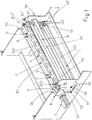
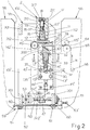
- the device comprises a main base frame 1 formed of rectangular side members 101, 101', oriented with the larger dimension vertically and mutually fixed with at least a pair of lower cross members 201 and with at least an upper cross member 301 positioned laterally and parallel to the rotary blade assembly 2 that comprises a sturdy body 102 with a rectangular cross section, provided with transverse openings 3 for lightening the structure and for aerodynamic purposes and that carries, inserted on the ends, hubs 202, 202' aligned with each other and with the longitudinal axis of the same body 102 that passes through slots 4, 4' of the side members 101, 101' on the outer side of which there are fixed the bearing cases 5, 5' that support these hubs and one of which, 5, positioned on the left when viewing Figs.
- the body 102 of the rotary blade assembly 2 is provided on one of the faces not affected by the openings 3, with at least a pair of symmetrical eyebolts 9 through which it is possible to move only the rotary blade assembly 2 or the whole base 1 with the rotary blade assembly and the fixed blade assembly, to be described below.
- the other face of the body 102 not affected by the eyebolts 9 ( Fig.
- the head 212 of the bolts 12 is prevented from rotating by a pin 13 parallel thereto, planted in a hole provided in the centreline of the bottom of the channel 10 and the head 212 slides on this pin with a perimeter recess 14 thereof, so that the same head 212 does not rotate but can move freely in an axial direction.
- the shank 112 of the bolts 12 has an end section of smaller diameter 112' that slides in an intermediate section 111 of smaller diameter of the holes 11 and that with the initial part that is housed in the same holes 11, is struck by a cylindrical coil spring 15 that axially thrusts each bolt towards the channel 10.
- the section of smaller diameter 112' of the shank of each bolt 12 is provided with a threaded axial hole 16 into which there is screwed the screw extension 117 of the shank of a counter-bolt 17, which with the portion of larger diameter 217 of the same shank housed is housed in the section of hole 11 that opens onto the face of the body 102 of the rotary knife provided with the eyebolts 9, with a widened section 211 in which there is housed and there rests as a result of the traction exerted by the spring 15, the head 317 of the same counter-bolt 17, which is designed to be rotated, for example, by means of a hexagonal wrench, as indicated by the axial socket 18 in Fig. 2 .
- a hexagonal wrench as indicated by the axial socket 18 in Fig. 2 .
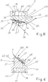
- the channel 10 there can be housed with high precision the lower and grooved part 119 of a metal bar that forms the body 19 of the holder block with the rotary blade, it being provided that this groove 119 has, for the majority of its extension, a U-shaped profile, illustrated in Fig. 5 , for the body of the holder block of the fixed blade, to be described below, and which has a C-shaped profile 119' only for small sections (see the sections 131' for the holder block 31 of the fixed blade of Fig. 5 ), which are affected by the head 112 of the bolts 12, so that these small sections with C-shaped profile can be clamped by the same heads 112 when a screwing action is exerted on the counter-bolt 17.
- the grooved part 119 of the holder body 19 is provided with end of travel means for longitudinal insertion into the channel 10, analogous to those to be described below with reference to Fig. 5 for the fixed blade.
- Figs. 8 and 9 it can be seen how the remaining part 219 of the holder body 19 is arranged to support with a partially cantilevered arrangement in the opposite direction to the direction of rotation of the body 102, an originally flat blade 20, the same length as the body 102, the projecting cutting edge 120 of which has a helical arrangement, with an inclination of around 20 degrees with respect to the ideal plane that contains the bottom of the groove 119, which is arranged on the lateral surface of an ideal cylinder having the rotation axis on that of the hubs 5, 5') and the midpoint H of which lies on the centreline of the web N of paper to be cut, as schematically illustrated in Fig.
- plan projection of the cutting edge of the same rotary blade is indicated with 120 and with a dashed line and where the plan projection of the cutting edge of the fixed blade, which passes through said midpoint H, is indicated with K and with a continuous line.
- the cutting edge 120 of the rotary blade 20 will start to cooperate with the cutting edge K of the fixed blade, for example starting from the left viewing Fig. 19 and will proceed progressively towards the right so as to make on the web N a cut T that will affect the same web for the whole of its width and that will be perfectly perpendicular to the sides of the same web N. As the web N moves in the direction indicated in Fig.
- Fig. 9 it can be seen how said helical arrangement of the rotary blade 20 means that its cutting edge 120 starts by projecting from the left end of the rear side of the body 219 and how progressively, proceeding towards the right, the same cutting edge 120 is inclined and moved back transversely from the rear side of the same body 219.
- the rotary blade 20 is formed by a rectangular steel strip, without holes and other fixing constraints, so that the same blade 20 can be arranged with both the longitudinal edges in the cutting function, so that when the exposed cutting edge 120 of the same blade is worn, the same blade can be reversed and installed with the other cutting edge opposite and parallel to the worn cutting edge exposed.
- the body 219 has on the whole of its length an intermediate and helical flattened surface 21 and a subsequent helical and lowered flattened surface 22 on which there is arranged a strip of elastomeric material 23 that is arranged substantially coplanar to the flattened surface 21 and that together with this latter forms the support of the transversely unexposed section of the blade 20.
- the helical flattened surface 21 is preceded by another helical flattened surface 24 that is substantially coplanar with the exposed face of the blade 20 and that forms the abutment step for the non-operating edge of the same blade 20 and the flattened surface 24 is followed by a raised flattened surface 25 resting on which is the longitudinal side of a sturdy metal pressure plate 26 that pinches the blade 20 on the intermediate flattened surface 21 and to a lesser extent also on the insert 23, with interposing of an elastomeric strip 27 with greater rigidity than the insert 23.
- the flattened surface 24 is provided perpendicularly with a plurality of threaded holes distributed adequately space from one another on the whole of the body 219, and there are screwed into these holes the shanks of screws 28 that pass through corresponding through holes of the plate 26. Due to the presence of the inserts made of elastomeric material 23 and 27, the blade 20 can react in an elastic and non-traumatic way to the stresses deriving from cooperation with the fixed blade and with the web N to be cut.
- the numeral 29 indicates the curved orbit with centre on the rotation axis 5, 5' of the rotary blade assembly 2, lying on which orbit is the cutting edge 120 of the same rotary blade 20.
- the cutting edge K Fig. 10
- the fixed blade assembly 30 which will now be described with reference to Figs. 1 to 6 and 11 .
- the assembly 30 comprises a flat rectangular blade 300, made of the same material as the rotary blade 20 considered previously, which forms with the orbit 29 of the same blade 20 an acute angle ⁇ , for example of around 45° and the cutting edge K of which is parallel to the rotation axis of the same blade 20. From the same Figs. 1-6 , it can be seen that the fixed blade 300 is supported by the inclined and composite plane of the holder body 31, the lower side of which has a grooved structure 131 as shown in Fig.
- the holder 31 with the blade 30 can be removed from the channel 32 that houses it.
- a handle 37 that projects from an opening 38 provided on the side member 101' of the main base 1 ( Figs. 1 , 2 , 3, 7 , 11 ), so that through the opening 38 it is possible to easily perform said operation of insertion and removal of the holder 31 with the lower blade 300.
- the same holder 31 is provided, on the end of the channel 131 next to the handle 37 ( Fig. 5 ), with a cross member 39 that cooperates with a stop provided on the proximal end of the guide channel 32.
- a similar solution is provided for the holder with the rotary blade 20, as indicated with 39' in Fig. 8 .
- the supporting body 33 of the fixed blade has end sections projecting from the holder 31 with the same fixed blade 300, provided with respective transverse horizontal holes to be able to be articulated through respective pins 40, 40' to the upper end of corresponding vertical slides 41, 41' installed on related outer supporting plates 42, 42', with the possibility of independent and selective adjustment of the position in height of these slides 41, 41', through guiding and blocking systems with slotted holes and screws 43, 43' and by means of screw and lead screw height adjusters 44, 44' that interact between the same slides 41, 41' and the small brackets 45, 45' below integral with said outer plates 42, 42'.
- the invention also provides for the possibility of adjusting the degree of interference of the fixed blade 300 in relation to the rotary blade 20, to adapt the cutting system of webs of different thickness and materials and to take up the small amounts of wear that progressively occur on the two blades.
- the outer plates 42, 42' are provided, on the top part thereof, with respective identical and symmetrical extensions 142, 142', positioned downstream of the fixed blade 300, oriented upwards and that with their upper end are articulated to pivot pins 46, 46' constrained to the side members 101, 101' of the base 1, these pivot pins being axially aligned with each other and being parallel to the same fixed blade 300.
- the axes of the pivot pins 46, 46' are positioned on an ideal horizontal plane on which the cutting edge K of the fixed blade 300 lies or is vertically positioned at a short distance and the same pivot pins 46, 46' are horizontally positioned at a short distance from the same cutting edge K.
- the outer plates 42, 42' have, in the lower part thereof, respective identical and symmetrical appendages 242, 242' that extend downwards, below the height of the small brackets 45, 45' and on the lower ends of which there are fixed perpendicularly identical pins 47, oriented one in the direction of the other, positioned with the axis on a common ideal plane that also contains the upper pivot pins 46, 46' and that is spaced by a few degrees from the verticality, for example by around 7-10 degrees. As the distance between the pins 47 and related pivot pins 46, 46' is almost seven or eight times greater than the horizontal distance between the same pivot pins 46.
- the pins 47 cooperate with respective vertically opening forks 48, which rest against said extensions 242, 242', and which are provided on the foot with respective lead screws 49 cooperating with horizontal screws 50, orthogonal to the pins 47, rotatably supported with one end by bushings 512 fixed to a lower cross member 201 of the main base frame 1 and that with the other end are connected to bevel gearboxes 52, in turn supported by the other lower cross member 201 of the same main frame 1, which are interconnected by a synchronizer shaft 53 and at least one of which is provided with a manual power take of 54 usable through large lateral vertical slots 55 (see Fig.
- a secondary base frame 56 for example of the packaging machine that uses the sheets obtained from the transverse cut of the web N by the device in question and that supports the means for feeding to the same device the web N unwound from a reel (see below).
- FIGs. 1 and 11 From Figs. 1 and 11 it can be seen that on the inner faces of the side members of the secondary base frame 56, there are fixed with their upper wing substantially coplanar to the lower side of the slots 55, sturdy brackets 59, 59' with L-shaped profile.
- the cutting device according to the invention rests with the side members 101, 101' of its main base 1 on the upper wing of the brackets 59, 59' and this wing is provided longitudinally with slotted holes 60 through which there pass screws 61 screwed into corresponding threaded holes provided on the ends of the cross members 201 of the base 1 of the same device.
- the number 64 indicates a plane with T-shaped profile, fixed to the side members 101, 101' of the main base 1 of the device, which guides the web N to be cut correctly between the rotary blade assembly 20 and the fixed blade assembly 300 of the same device in question, with an orientation tangential to the orbit 29 of rotation of the upper blade 20, it being provided that the same web N comes from a pair of driving rollers 65, 65', the lower 65 of which has a large diameter, has a surface with a high coefficient of friction on the web N, is motorized and is affected by the same web N for a large section of its circumference, due to guiding of the same web N on an idle roller 66 below. All the rollers considered above and all the means that control unwinding of the web N to be cut from the reel are installed on the secondary base frame 56.
Landscapes
- Life Sciences & Earth Sciences (AREA)
- Forests & Forestry (AREA)
- Engineering & Computer Science (AREA)
- Mechanical Engineering (AREA)
- Details Of Cutting Devices (AREA)
- Perforating, Stamping-Out Or Severing By Means Other Than Cutting (AREA)
- Nonmetal Cutting Devices (AREA)
Claims (8)
- Eine Vorrichtung mit schnell auswechselbaren Klingen zum Querschneiden oder Perforieren, und zwar jeweils über die gesamte Breite und schrittweise, von fortlaufenden und bewegenden Bahnen (N) aus Papier, Kunststoff oder anderen Materialien, auch mit unterschiedlicher Stärke, ausgerüstet mit einer feststehenden Baugruppe mit Klingen (30, 300) und einer rotierenden Baugruppe mit Klingen (2, 20), zwischen denen die Bahn (N) über eine Gleitfläche (64) quer geführt und längs beschickt wird, und zwar durch entsprechende Antriebs- und Schubelemente (65, 65'), dadurch gekennzeichnet, dass die selbe feststehende Baugruppe mit Klingen (30, 300) und die rotierende Baugruppe mit Klingen (2, 20) jeweils auf seitliche Elemente (101, 101') eines Hauptgrundrahmens (1) montiert sind, mit entsprechenden Antriebselementen (7) und Elementen zur Justierung des Parallelismus und des Grads des Eingreifens zwischen den genannten zwei Klingen (20, 300), wobei der genannte Hauptgrundrahmen (1) entfernbar an einem Nebengrundrahmen (56) montiert ist, und zwar mit Elementen zur Justierung der Querausrichtung des selben Hauptrahmens (1) mit den jeweilige Baugruppen mit Klingen (2, 20, 3, 300) in Bezug auf die Längsachse der zu schneidenden Bahn (N), um die dynamische Durchführung eines Schnitts (T) auf diese Bahn zu gestatten, welcher senkrecht zu den Längsseiten der Bahn selbst verläuft, wobei diese Vorrichtung mit Elementen (9) versehen ist, die eine schnelle Installation ermöglichen sowie bei Bedarf den Ersatz durch eine neue Vorrichtung, und zwar jedes Mal dann, wenn beide der genannten Klingen (2, 20, 3, 300) umfassendere Wartungs- und Justierungseingriffe benötigen, um die Ausfallzeiten der Verpackungsmaschine während der Auswechslung der Vorrichtung selbst zu begrenzen,
dadurch gekennzeichnet, dass
der genannte Grundrahmen (1) mit seinen Seitenelementen (101, 101') auf entsprechenden Halterungen (59, 59') aufliegt, welche an der unteren Seite breiter senkrechter Schlitze (55) befestigt sind, die an seitlichen Elementen des Nebengrundrahmens (56) vorgesehen sind, wobei die genannten Halterungen jeweils mit längs geschlitzten Öffnungen (60) versehen sind, durch die Schrauben (61) hindurch führen, die mit entsprechenden Gewindeöffnungen verschraubt sind, welche sich unter der Hauptbasis (1) der Vorrichtung selbst befinden, so dass es durch Nutzung eines ausreichenden Querspielraums, der zwischen einem Schaft der genannten Schrauben (61) und entsprechenden Öffnungen der genannten geschlitzten Öffnungen (60) beziehungsweise durch Nutzung einer entsprechend gebogenen Form der selben geschlitzten Öffnungen (60) und durch Einwirken auf die Schrauben- und Leitspindel-Einstellvorrichtungen (63, 63'), welche sich an den gegenüberliegenden Querseiten der genannten Halterungen (59, 59') befinden, und zwar so, dass sie mit ihrer jeweiligen Schraube senkrecht an entgegengesetzten Seiten der Hauptbasis (1) selbst interagieren, möglich ist, die Querausrichtung des Hauptgrundrahmens (1) mit den Komponenten, die er trägt, per Drehung des Hauptgrundrahmens auf einer senkrechten Achse (H) zu justieren, welche durch die Mittellinien des Hauptgrundrahmens führt, so dass Schnitte (T) an der sich bewegenden Bahn (N), senkrecht zu den Längsseiten der Bahn (N) selbst, durchgeführt werden können. - Eine Vorrichtung gemäß Anspruch 1, wobei die rotierende Baugruppe mit Klingen (2, 20) über der feststehenden Baugruppe mit Klingen (30, 300) angeordnet und mit einem stabilen geradlinigen Körper (102) mit Endanschluss (202, 202') ausgerüstet ist, welche drehbar durch die seitlichen Elemente (101, 101') des Hauptgrundrahmens (1) gehalten werden, und zwar mit Hilfe von entsprechenden Lagergehäusen (5, 5'), wobei Augenschrauben (9) an einer Fläche des genannten Körpers (102) montiert sind, um die Handhabung des Ganzen bei Installations- und Ausbauschritten zu vereinfachen, während sich an der der mit den Augenschrauben (9) gegenüberliegenden Fläche der genannte Körper (102) eine entfernbare Klinge (20) mit einer Schneide (120) mit spiralförmiger Verlängerung und mit der Mitte der Krümmung auf der Drehachse der genannten Anschluss (202, 202') trägt, von denen einer jeweils durch sein Lagergehäuse hindurch führt und durch Zwischenschaltung eines entsprechenden Sicherheitsverbinders (6) mit einem Rotationsgetriebemotor (7) verbunden ist, und zwar vorzugsweise mit einem Elektromotor für die elektronische Geschwindigkeits- und Phasenkontrolle, welcher von einer Halterung (8) getragen wird, die an dem naheliegenden seitlichen Element (101) des genannten Hauptgrundrahmens (1) befestigt ist und durch einen der genannten breiten senkrechten Schlitze (55) des genannten Nebengrundrahmens (56) herausragt.
- Eine Vorrichtung gemäß Anspruch 2, wobei die genannte feststehende Baugruppe mit Klingen (30) mit einem stabilen geradlinigen Körper (33) versehen ist, an dessen in Richtung der rotierenden oberen Baugruppe mit Klingen (2, 20) gerichteten Fläche eine feststehende Klinge (300) mit einer geradlinigen Schneide (K) entfernbar montiert ist, wobei der genannte Körper (33) an den entgegengesetzten Enden jeweils mit entsprechenden waagerechten Queröffnungen zur Gelenkverbindung durch entsprechende Stifte (40, 40') mit dem oberen Ende entsprechender senkrechter Führungen (41, 41') versehen ist, welche jeweils auf dazugehörige äußere Halteplatten (42, 42') montiert sind, mit der Möglichkeit einer unabhängigen und selektiven Justierung der Höhenverstellung der genannten Führungen (41, 41') mit Hilfe von Führungs- und Verriegelungssystemen mit geschlitzten Öffnungen und Schrauben (43, 43') und über Schrauben- und Leitspindel-Höhenversteller (44, 44'), welche zwischen den Führungen selbst (41, 41') und den kleinen Halterungen (45, 45') darunter interagieren, welche aus einem Stück mit den genannten äußeren Platten (42, 42') sind, wobei das Ganze vorgesehen ist, um eine exakt präzise und parallele Anordnung zwischen der geradlinigen Schneide (K) der feststehenden Klinge (300) in Bezug auf die Grundrissprojektion der spiralförmigen Schneide (120) der rotierenden Klingen (20) sicherzustellen, und zwar sogar bei fehlender Hochpräzision bei der Bearbeitung des Hauptgrundrahmens (1) und der Installation aller Teile, welche die feststehende Klinge (300) selbst tragen, darauf.
- Eine Vorrichtung gemäß Anspruch 3, wobei die genannten äußeren Platten (42, 42') an deren oberem Bereich mit entsprechenden identischen und symmetrischen Verlängerungen (142, 142') ausgerüstet sind, welche der feststehenden Klinge (300) nachgelagert und nach oben gerichtet sind, und die mit ihrem oberen Ende über Drehzapfen (46, 46') gelenkig verbunden sind, welche wiederum fest mit den seitlichen Elementen (101, 101') des Hauptrahmens (1) verbunden sind, wobei diese Drehzapfen (46, 46') axial miteinander ausgerichtet, parallel zu der feststehenden Klinge (300) selbst und auf einer ideellen horizontalen Ebene angeordnet sind, auf der die Schneide (K) der feststehenden Klinge (300) im Wesentlichen liegt, und sie horizontal in geringem Abstand von der Schneide (K) selbst positioniert sind, wobei die genannten äußeren Platten (42, 42') jeweils in ihrem unteren Bereich mit entsprechenden identischen und symmetrischen Fortsätzen (242, 242') versehen sind, welche sich nach unten erstrecken, unterhalb der Höhe der genannten kleinen Halterungen (45, 45') und an den unteren Enden dieses Fortsatzes (242, 242') senkrecht identische Zapfen (47) befestigt sind, welche sich jeweils in die Richtung des anderen richten und die mit der Achse auf einer gemeinsamen ideellen Ebene angeordnet sind, welche ebenfalls die oberen Drehzapfen (46, 46') enthält und die um wenige Grade von der Vertikalität beabstandet ist, zum Beispiel um 7-10 Grad, wobei vorgesehen ist, dass mit den genannten Zapfen (47) entsprechende sich senkrecht öffnende Gabelstücke (48) kooperieren, welche sich gegen die genannten Verlängerungen (242, 242') lehnen und am Fuß mit entsprechenden Leitspindeln (49) ausgerüstet sind, die wiederum mit horizontalen Schrauben (50) kooperieren, welche jeweils rechtwinklig zu den Zapfen (47) angeordnet sind und drehbar mit einem Ende durch entsprechende Buchsen (51) gehalten werden, die an einem unteren Querelement (201) des Hauptgrundrahmens (1) befestigt sind und die mit dem anderen Ende mit Kegelradgetrieben (42) verbunden sind, welche von dem anderen unteren Querelement (201) des selben Hauptrahmens (1) getragen werden, wobei diese Getriebe (42) jeweils durch eine Synchronwelle (53) miteinander verbunden sind und mindestens eins der Getriebe (52) selbst mit einem manuellen Nebenantrieb (54) ausgerüstet ist, welcher durch einen der breiten seitlichen senkrechten Schlitze (55) verwendet werden kann, die sich an dem genannten Nebengrundrahmen (56) befinden, wobei vorgesehen ist, dass es durch diesen Nebenantrieb (54) möglich ist, den Grad des Eingreifens der unteren Klinge (300) in Bezug auf die obere rotierende Klinge (20) entsprechend so einzustellen, dass die Schneidevorrichtung geeignet ist, Bahnen (N) mit unterschiedlicher Stärke und/oder aus verschiedenen Materialien zu bearbeiten und den Verschleiß der Klingen (300, 20) selbst auszugleichen.
- Eine Vorrichtung gemäß Anspruch 4, dadurch gekennzeichnet, dass es nach der Justierung der feststehenden Klinge (300) durch den genannten Nebenantrieb (54) möglich ist, die genannten schwingenden Platten (42, 42') jeweils an den seitlichen Elementen (101, 101') der Hauptbasis (1) mit Hilfe von Schrauben (57, 57') zu verriegeln, welche in den schwingenden Platten selbst (42, 42') verschraubt sind, die durch die geschlitzten Öffnungen (58, 58') hindurch führen, welche sich an den genannten seitlichen Elementen (101, 101') befinden und die Form eines Kreisausschnitts haben, mit der Mitte der Krümmung auf den genannten Drehzapfen (46, 46'), wobei der Kopf der genannten Schrauben (57, 57') jeweils an den Außenflächen der genannten Seitenelemente (101, 101') angeordnet ist, die durch die genannten breiten senkrechten Schlitze (55) des genannten Nebengrundrahmens (56) freigelegt werden.
- Eine Vorrichtung gemäß Anspruch 2, wobei beide der genannten Klingen (20, 300) auf entsprechende geradlinige Halteblöcke (19, 31) montiert sind, welche mit Hochpräzision in Längsrinnen (10, 32) der genannten entsprechenden Tragkörper (102, 33) eingesetzt werden können, in denen die Halteblöcke selbst (19, 31) schnell und sicher ver- und entriegelt werden können, und zwar mit Hilfe von entsprechenden, pilzförmigen Klemmbolzen (12, 12'), die durch entsprechende Federn (15, 15') jeweils in Richtung der Entriegelungsstellung gespannt werden und die mit Schrauben- und Leitspindelelementen verriegelt werden können, und zwar zumindest für den Halteblock (19) mit rotierender Klinge, während für den Halteblock (31) der feststehenden Klinge sie mit Hilfe von exzentrischen Hebeln (34-36) verriegelt werden können, wobei vorgesehen ist, dass die Rotation des Kopfs (212, 212') der genannten pilzförmigen Bolzen (12, 12') durch entsprechende Elemente (13, 14) verhindert wird, und wobei vorgesehen ist, dass sie in der verriegelten Stellung per Reibung mit Teilen kooperieren, welche ein C-förmiges Profil (119', 131') des unteren und gerillten Profils (119, 131) der genannten Halteblöcke (19, 31) mit den genannten Klingen (20, 300) aufweisen, so dass eine schnelle Auswechslung der genannten Blöcke mit Klingen selbst gestattet wird, und zwar jedes Mal dann, wenn die Klingen sich während des Betriebs abnutzen.
- Eine Vorrichtung gemäß Anspruch 6, dadurch gekennzeichnet, dass wenn der Halteblock (19) mit der rotierenden Klinge (20) sich in der höchsten Eckstellung seiner Rotationsbahn befindet, der Haltekörper selbst jeweils über den seitlichen Elementen (101, 101') des Hauptgrundrahmens (1) zu liegen kommt, so dass der genannte Halteblock (19) mit einer Längsbewegung zur Entfernung problemlos ausgewechselt werden kann, ohne mit der Hauptbasis (1) selbst zu interferieren, während der Haltekörper (31) mit der feststehenden Klinge (300) an einem Ende mit einem freitragenden Griff (37) versehen ist, der durch eine Öffnung (38) des naheliegenden Seitenelements (101') der Hauptbasis (1) führt, und zwar so, dass er auch durch einen der breiten senkrechten Schlitze (55) der genannten Nebenbasis (56) hindurch verwendet werden kann.
- Eine Vorrichtung gemäß Anspruch 6, wobei die genannten geradlinigen Halteblöcke (19, 31) der rotierenden Klinge (20) und der feststehenden Klinge (300) diese Klingen mit Hilfe einer abgeflachten Zwischenfläche (21, 21') und einer darauf folgenden abgesenkten, abgeflachten Fläche (22, 22') tragen, auf denen ein Streifen aus Elastomermaterial (23, 23') angeordnet ist, der im Wesentlichen koplanar zu der genannten abgeflachten Fläche (21, 21') angeordnet ist, und der mit dieser die Halterung für den quer nicht freiliegenden Abschnitt der Klinge (20, 300) bildet, wobei der genannten abgeflachten Zwischenfläche (21, 21') eine abgeflachte Fläche (24, 24') vorausgeht, welche sich im Wesentlichen koplanar zu der freiliegenden Fläche der Klinge (20, 300) verhält und die Anschlagstufe für die nicht operierende Kante der Klinge selbst (20, 300) bildet, und die abgeflachte Fläche selbst (24, 24') jeweils von einer erhöhten abgeflachten Fläche (25, 25') gefolgt wird, auf der die Längsseite einer Metall-Druckplatte (26, 26') aufliegt, welche die Klinge (20, 300) an der abgeflachten Zwischenfläche (21, 21') überlagert und kneift, und in geringerem Maße auch an dem Einsatz (23, 23'), und zwar bei Einfügung eines Elastomerstreifens (27, 27'), welcher steifer ist als der gegenüberliegende Einsatz (23, 23'), wobei vorgesehen ist, dass die genannte abgeflachte Fläche (24, 24') mit einer Vielzahl von Gewindeöffnungen versehen ist, welche jeweils entsprechend über die gesamte Länge der Halteblöcke (19, 31) voneinander beabstandet sind und dass die Schraubenschäfte (28, 28) jeweils in diesen Öffnungen verschraubt sind, die durch entsprechende durchgehende Öffnungen der Klemmplatte (26, 26') hindurch führen, wobei vorgesehen ist, dass die Klingen (20, 300) infolge der Anwesenheit der genannten Einsätze aus Elastomermaterial (23, 23', 27, 27') elastisch auf die Belastungen reagieren können, welche von der wechselseitigen Zusammenarbeit und der Zusammenarbeit mit der Bahn (N) herrühren, die geschnitten werden soll.
Priority Applications (1)
| Application Number | Priority Date | Filing Date | Title |
|---|---|---|---|
| RS20220073A RS62877B1 (sr) | 2015-07-22 | 2016-07-05 | Uređaj sa brzo izmenjivim sečivima, radi poprečnog sečenja ili perforacije pokretnih kolutova papira, plastike ili drugih materijala |
Applications Claiming Priority (2)
| Application Number | Priority Date | Filing Date | Title |
|---|---|---|---|
| ITUB2015A002389A ITUB20152389A1 (it) | 2015-07-22 | 2015-07-22 | Apparato con lame a ricambio rapido, per tagliare o per perforare trasversalmente, per tutta la larghezza ed in modo progressivo, dei nastri mobili, di carta, di materia plastica o d'altri materiali. |
| PCT/IB2016/054016 WO2017013516A1 (en) | 2015-07-22 | 2016-07-05 | Device with quick change blades, for transverse cutting or perforation, for the whole of the width and progressively, of moving webs of paper, plastic or other materials |
Publications (2)
| Publication Number | Publication Date |
|---|---|
| EP3325236A1 EP3325236A1 (de) | 2018-05-30 |
| EP3325236B1 true EP3325236B1 (de) | 2021-11-03 |
Family
ID=54364503
Family Applications (1)
| Application Number | Title | Priority Date | Filing Date |
|---|---|---|---|
| EP16736629.3A Active EP3325236B1 (de) | 2015-07-22 | 2016-07-05 | Vorrichtung mit schnell auswechselbaren klingen zum querschneiden oder perforieren von bahnen aus papier, kunststoff oder anderen materialien |
Country Status (8)
| Country | Link |
|---|---|
| US (1) | US20180200910A1 (de) |
| EP (1) | EP3325236B1 (de) |
| CN (1) | CN107949460B (de) |
| BR (1) | BR112018000951B1 (de) |
| ES (1) | ES2905623T3 (de) |
| IT (1) | ITUB20152389A1 (de) |
| RS (1) | RS62877B1 (de) |
| WO (1) | WO2017013516A1 (de) |
Families Citing this family (15)
| Publication number | Priority date | Publication date | Assignee | Title |
|---|---|---|---|---|
| JP6896379B2 (ja) * | 2015-07-02 | 2021-06-30 | シールド・エアー・コーポレイション(ユーエス) | 膨張クッションを提供するシステム |
| DE102017110231B4 (de) * | 2017-05-11 | 2019-09-26 | Heusch Gmbh & Co. Kg | Schneidvorrichtung sowie Verfahren zu deren Betrieb |
| US10786922B2 (en) * | 2017-05-16 | 2020-09-29 | Urschel Laboratories, Inc. | Modular units, clamping assemblies, and slicing machines equipped therewith |
| CN107498605A (zh) * | 2017-09-07 | 2017-12-22 | 苏州川日精密机械有限公司 | 一种跳刀裁切机的裁切装置 |
| US10857690B2 (en) | 2018-09-11 | 2020-12-08 | The Procter & Gamble Company | Method and apparatus for adjusting and maintaining a position of a cutting surface of a perforating apparatus |
| DE102019102477A1 (de) * | 2019-01-31 | 2020-08-06 | Manroland Goss Web Systems Gmbh | Messerleiste, Schneidbalken und Einstellvorrichtung zur vereinfachten Einstellung der Messerhöhe |
| WO2020221409A1 (en) * | 2019-05-01 | 2020-11-05 | Kobots Aps | Portable automated panel cutter |
| FI12451U1 (fi) * | 2019-05-15 | 2019-08-15 | Valmet Technologies Oy | Teräjärjestely ja poikkileikkauslaite |
| CN110170695B (zh) * | 2019-05-28 | 2024-06-21 | 宁波同人轴承有限公司 | 一种金属管件自动切割刀具 |
| CN112064325A (zh) * | 2020-08-21 | 2020-12-11 | 耒阳市康意电子箱包科技有限公司 | 一种用于箱包加工的面料裁剪辅助装置 |
| CN112331968B (zh) * | 2020-11-10 | 2023-09-05 | 迈科新能源(深圳)有限公司 | 一种锂电池盖板生产加工用分切刀组 |
| CN113997352B (zh) * | 2021-09-09 | 2023-10-20 | 山东华滋自动化技术股份有限公司 | 一种蓝膜灰胶割缝装置 |
| CN113977688B (zh) * | 2021-10-25 | 2023-08-04 | 广州华夏职业学院 | 一种会计专业用单据定位裁剪装置 |
| CN115556160B (zh) * | 2022-10-14 | 2023-07-21 | 井冈山市吉源农业生态发展有限公司 | 一种糯米笋生产工艺及生产装置 |
| CN118024326B (zh) * | 2024-04-11 | 2024-07-05 | 达森特(福建)生活用品有限公司 | 一种乳霜纸巾自动化切割生产系统及方法 |
Citations (2)
| Publication number | Priority date | Publication date | Assignee | Title |
|---|---|---|---|---|
| US5117718A (en) * | 1991-04-23 | 1992-06-02 | Integrated Design Corporation | Web perforating apparatus |
| DE4202186A1 (de) * | 1992-01-28 | 1993-07-29 | Will E C H Gmbh & Co | Schneidapparat |
Family Cites Families (12)
| Publication number | Priority date | Publication date | Assignee | Title |
|---|---|---|---|---|
| US1631879A (en) * | 1924-12-05 | 1927-06-07 | Molins Walter Everett | Machine for automatically cutting moving webs of paper or other materials into sheets |
| GB668082A (en) * | 1948-12-15 | 1952-03-12 | Leslie Gordon Forster | Improvements in or relating to means for cutting thin material |
| US2632510A (en) * | 1951-11-09 | 1953-03-24 | Hamilton Tool Co | Cutoff cylinder |
| CA614504A (en) * | 1957-08-30 | 1961-02-14 | M. Kwitek Edwin | Web cutting apparatus |
| GB1238254A (de) * | 1968-02-24 | 1971-07-07 | ||
| JPH03205134A (ja) * | 1989-12-31 | 1991-09-06 | Somar Corp | フイルム張付方法及びその実施装置 |
| SE509840C2 (sv) * | 1995-11-06 | 1999-03-15 | Straalfors Ab | Skäranordning för skärning av sammanhängande banor |
| JPH09262793A (ja) * | 1996-03-27 | 1997-10-07 | Hitachi Metals Ltd | シート材切断装置およびその調整方法 |
| JP2003311679A (ja) * | 2002-04-25 | 2003-11-05 | Tokyo Autom Mach Works Ltd | 切断装置及び切断方法 |
| EP1525960A1 (de) * | 2003-10-20 | 2005-04-27 | Müller Martini Holding AG | Schneidvorrichtung zum Schneiden einer Materialbahn |
| ITBO20060517A1 (it) * | 2006-07-04 | 2006-10-03 | Gd Spa | Dispositivo di taglio per il taglio di un nastro mediante lame controinclinate. |
| CN101015390A (zh) * | 2007-02-12 | 2007-08-15 | 山东中烟工业公司滕州卷烟厂 | 薄片断丝刀 |
-
2015
- 2015-07-22 IT ITUB2015A002389A patent/ITUB20152389A1/it unknown
-
2016
- 2016-07-05 RS RS20220073A patent/RS62877B1/sr unknown
- 2016-07-05 CN CN201680042901.4A patent/CN107949460B/zh active Active
- 2016-07-05 EP EP16736629.3A patent/EP3325236B1/de active Active
- 2016-07-05 ES ES16736629T patent/ES2905623T3/es active Active
- 2016-07-05 WO PCT/IB2016/054016 patent/WO2017013516A1/en not_active Ceased
- 2016-07-05 US US15/743,965 patent/US20180200910A1/en not_active Abandoned
- 2016-07-05 BR BR112018000951-2A patent/BR112018000951B1/pt active IP Right Grant
Patent Citations (2)
| Publication number | Priority date | Publication date | Assignee | Title |
|---|---|---|---|---|
| US5117718A (en) * | 1991-04-23 | 1992-06-02 | Integrated Design Corporation | Web perforating apparatus |
| DE4202186A1 (de) * | 1992-01-28 | 1993-07-29 | Will E C H Gmbh & Co | Schneidapparat |
Also Published As
| Publication number | Publication date |
|---|---|
| ITUB20152389A1 (it) | 2017-01-22 |
| US20180200910A1 (en) | 2018-07-19 |
| EP3325236A1 (de) | 2018-05-30 |
| CN107949460A (zh) | 2018-04-20 |
| CN107949460B (zh) | 2020-08-21 |
| WO2017013516A1 (en) | 2017-01-26 |
| BR112018000951A2 (pt) | 2018-09-04 |
| ES2905623T3 (es) | 2022-04-11 |
| BR112018000951B1 (pt) | 2021-01-19 |
| HK1253939A1 (zh) | 2019-07-05 |
| RS62877B1 (sr) | 2022-02-28 |
Similar Documents
| Publication | Publication Date | Title |
|---|---|---|
| US20180200910A1 (en) | Device with quick change blades, for transverse cutting or perforation, for the whole of the width and progressively, of moving webs of paper, plastic or other materials | |
| FI75299C (fi) | Slitsverk. | |
| EP3619011B1 (de) | Verfahren zur verringerung von etikettenabfall unter verwendung einer schneidvorrichtung | |
| EP2459454B1 (de) | Schneideinheit für etikettiermaschinen | |
| DE69515784T2 (de) | Rotierendes Schneidwerkzeug | |
| US4885964A (en) | Tape slitter adjustment means | |
| CN212146714U (zh) | 一种方便操作的分条机分切机构 | |
| ES2972064T3 (es) | Disposición de cuchilla y máquina de corte transversal | |
| CN111571687A (zh) | 一种高性能纺织布料切割机 | |
| EP1525962A2 (de) | Messeranordnung für eine Rotationsschneidemaschine | |
| US4909110A (en) | Tube clamping apparatus | |
| JP2009050981A (ja) | 傷痕加工装置 | |
| CN119284623B (zh) | 一种可自动切料的离型纸分切装置 | |
| JP7645228B2 (ja) | キャップ切断装置 | |
| CN214419006U (zh) | 一种标签分切机 | |
| CN118650196B (zh) | 一种制管纵剪机 | |
| CN210236658U (zh) | 印刷机的分条装置 | |
| FI96392C (fi) | Tukilaite | |
| CN110182426B (zh) | 用于分切塑料勺包装带的冷切机 | |
| CN113748003A (zh) | 刀辊 | |
| CN215094037U (zh) | 一种用于更换切刀的工装 | |
| HK1253939B (zh) | 具有快速替换刀片的装置 | |
| JPH0615597A (ja) | 切断装置 | |
| KR100605513B1 (ko) | 타이어 재단공정의 코드지 재단장치 | |
| CN220349163U (zh) | 一种纸盒开槽用刀具调节装置 |
Legal Events
| Date | Code | Title | Description |
|---|---|---|---|
| STAA | Information on the status of an ep patent application or granted ep patent |
Free format text: STATUS: THE INTERNATIONAL PUBLICATION HAS BEEN MADE |
|
| PUAI | Public reference made under article 153(3) epc to a published international application that has entered the european phase |
Free format text: ORIGINAL CODE: 0009012 |
|
| STAA | Information on the status of an ep patent application or granted ep patent |
Free format text: STATUS: REQUEST FOR EXAMINATION WAS MADE |
|
| 17P | Request for examination filed |
Effective date: 20180209 |
|
| AK | Designated contracting states |
Kind code of ref document: A1 Designated state(s): AL AT BE BG CH CY CZ DE DK EE ES FI FR GB GR HR HU IE IS IT LI LT LU LV MC MK MT NL NO PL PT RO RS SE SI SK SM TR |
|
| AX | Request for extension of the european patent |
Extension state: BA ME |
|
| DAV | Request for validation of the european patent (deleted) | ||
| DAX | Request for extension of the european patent (deleted) | ||
| STAA | Information on the status of an ep patent application or granted ep patent |
Free format text: STATUS: EXAMINATION IS IN PROGRESS |
|
| 17Q | First examination report despatched |
Effective date: 20190628 |
|
| GRAP | Despatch of communication of intention to grant a patent |
Free format text: ORIGINAL CODE: EPIDOSNIGR1 |
|
| STAA | Information on the status of an ep patent application or granted ep patent |
Free format text: STATUS: GRANT OF PATENT IS INTENDED |
|
| INTG | Intention to grant announced |
Effective date: 20201028 |
|
| 19U | Interruption of proceedings before grant |
Effective date: 20201208 |
|
| 19W | Proceedings resumed before grant after interruption of proceedings |
Effective date: 20210601 |
|
| GRAS | Grant fee paid |
Free format text: ORIGINAL CODE: EPIDOSNIGR3 |
|
| GRAA | (expected) grant |
Free format text: ORIGINAL CODE: 0009210 |
|
| STAA | Information on the status of an ep patent application or granted ep patent |
Free format text: STATUS: THE PATENT HAS BEEN GRANTED |
|
| AK | Designated contracting states |
Kind code of ref document: B1 Designated state(s): AL AT BE BG CH CY CZ DE DK EE ES FI FR GB GR HR HU IE IS IT LI LT LU LV MC MK MT NL NO PL PT RO RS SE SI SK SM TR |
|
| REG | Reference to a national code |
Ref country code: GB Ref legal event code: FG4D |
|
| REG | Reference to a national code |
Ref country code: AT Ref legal event code: REF Ref document number: 1443563 Country of ref document: AT Kind code of ref document: T Effective date: 20211115 Ref country code: CH Ref legal event code: EP |
|
| REG | Reference to a national code |
Ref country code: IE Ref legal event code: FG4D |
|
| REG | Reference to a national code |
Ref country code: DE Ref legal event code: R096 Ref document number: 602016065714 Country of ref document: DE |
|
| REG | Reference to a national code |
Ref country code: LT Ref legal event code: MG9D |
|
| REG | Reference to a national code |
Ref country code: NL Ref legal event code: MP Effective date: 20211103 |
|
| REG | Reference to a national code |
Ref country code: AT Ref legal event code: MK05 Ref document number: 1443563 Country of ref document: AT Kind code of ref document: T Effective date: 20211103 |
|
| REG | Reference to a national code |
Ref country code: ES Ref legal event code: FG2A Ref document number: 2905623 Country of ref document: ES Kind code of ref document: T3 Effective date: 20220411 |
|
| PG25 | Lapsed in a contracting state [announced via postgrant information from national office to epo] |
Ref country code: LT Free format text: LAPSE BECAUSE OF FAILURE TO SUBMIT A TRANSLATION OF THE DESCRIPTION OR TO PAY THE FEE WITHIN THE PRESCRIBED TIME-LIMIT Effective date: 20211103 Ref country code: FI Free format text: LAPSE BECAUSE OF FAILURE TO SUBMIT A TRANSLATION OF THE DESCRIPTION OR TO PAY THE FEE WITHIN THE PRESCRIBED TIME-LIMIT Effective date: 20211103 Ref country code: BG Free format text: LAPSE BECAUSE OF FAILURE TO SUBMIT A TRANSLATION OF THE DESCRIPTION OR TO PAY THE FEE WITHIN THE PRESCRIBED TIME-LIMIT Effective date: 20220203 Ref country code: AT Free format text: LAPSE BECAUSE OF FAILURE TO SUBMIT A TRANSLATION OF THE DESCRIPTION OR TO PAY THE FEE WITHIN THE PRESCRIBED TIME-LIMIT Effective date: 20211103 |
|
| PG25 | Lapsed in a contracting state [announced via postgrant information from national office to epo] |
Ref country code: IS Free format text: LAPSE BECAUSE OF FAILURE TO SUBMIT A TRANSLATION OF THE DESCRIPTION OR TO PAY THE FEE WITHIN THE PRESCRIBED TIME-LIMIT Effective date: 20220303 Ref country code: SE Free format text: LAPSE BECAUSE OF FAILURE TO SUBMIT A TRANSLATION OF THE DESCRIPTION OR TO PAY THE FEE WITHIN THE PRESCRIBED TIME-LIMIT Effective date: 20211103 Ref country code: PT Free format text: LAPSE BECAUSE OF FAILURE TO SUBMIT A TRANSLATION OF THE DESCRIPTION OR TO PAY THE FEE WITHIN THE PRESCRIBED TIME-LIMIT Effective date: 20220303 Ref country code: PL Free format text: LAPSE BECAUSE OF FAILURE TO SUBMIT A TRANSLATION OF THE DESCRIPTION OR TO PAY THE FEE WITHIN THE PRESCRIBED TIME-LIMIT Effective date: 20211103 Ref country code: NO Free format text: LAPSE BECAUSE OF FAILURE TO SUBMIT A TRANSLATION OF THE DESCRIPTION OR TO PAY THE FEE WITHIN THE PRESCRIBED TIME-LIMIT Effective date: 20220203 Ref country code: NL Free format text: LAPSE BECAUSE OF FAILURE TO SUBMIT A TRANSLATION OF THE DESCRIPTION OR TO PAY THE FEE WITHIN THE PRESCRIBED TIME-LIMIT Effective date: 20211103 Ref country code: LV Free format text: LAPSE BECAUSE OF FAILURE TO SUBMIT A TRANSLATION OF THE DESCRIPTION OR TO PAY THE FEE WITHIN THE PRESCRIBED TIME-LIMIT Effective date: 20211103 Ref country code: HR Free format text: LAPSE BECAUSE OF FAILURE TO SUBMIT A TRANSLATION OF THE DESCRIPTION OR TO PAY THE FEE WITHIN THE PRESCRIBED TIME-LIMIT Effective date: 20211103 Ref country code: GR Free format text: LAPSE BECAUSE OF FAILURE TO SUBMIT A TRANSLATION OF THE DESCRIPTION OR TO PAY THE FEE WITHIN THE PRESCRIBED TIME-LIMIT Effective date: 20220204 |
|
| PG25 | Lapsed in a contracting state [announced via postgrant information from national office to epo] |
Ref country code: SM Free format text: LAPSE BECAUSE OF FAILURE TO SUBMIT A TRANSLATION OF THE DESCRIPTION OR TO PAY THE FEE WITHIN THE PRESCRIBED TIME-LIMIT Effective date: 20211103 Ref country code: SK Free format text: LAPSE BECAUSE OF FAILURE TO SUBMIT A TRANSLATION OF THE DESCRIPTION OR TO PAY THE FEE WITHIN THE PRESCRIBED TIME-LIMIT Effective date: 20211103 Ref country code: RO Free format text: LAPSE BECAUSE OF FAILURE TO SUBMIT A TRANSLATION OF THE DESCRIPTION OR TO PAY THE FEE WITHIN THE PRESCRIBED TIME-LIMIT Effective date: 20211103 Ref country code: EE Free format text: LAPSE BECAUSE OF FAILURE TO SUBMIT A TRANSLATION OF THE DESCRIPTION OR TO PAY THE FEE WITHIN THE PRESCRIBED TIME-LIMIT Effective date: 20211103 Ref country code: DK Free format text: LAPSE BECAUSE OF FAILURE TO SUBMIT A TRANSLATION OF THE DESCRIPTION OR TO PAY THE FEE WITHIN THE PRESCRIBED TIME-LIMIT Effective date: 20211103 Ref country code: CZ Free format text: LAPSE BECAUSE OF FAILURE TO SUBMIT A TRANSLATION OF THE DESCRIPTION OR TO PAY THE FEE WITHIN THE PRESCRIBED TIME-LIMIT Effective date: 20211103 |
|
| REG | Reference to a national code |
Ref country code: DE Ref legal event code: R097 Ref document number: 602016065714 Country of ref document: DE |
|
| PLBE | No opposition filed within time limit |
Free format text: ORIGINAL CODE: 0009261 |
|
| STAA | Information on the status of an ep patent application or granted ep patent |
Free format text: STATUS: NO OPPOSITION FILED WITHIN TIME LIMIT |
|
| 26N | No opposition filed |
Effective date: 20220804 |
|
| PG25 | Lapsed in a contracting state [announced via postgrant information from national office to epo] |
Ref country code: AL Free format text: LAPSE BECAUSE OF FAILURE TO SUBMIT A TRANSLATION OF THE DESCRIPTION OR TO PAY THE FEE WITHIN THE PRESCRIBED TIME-LIMIT Effective date: 20211103 |
|
| PG25 | Lapsed in a contracting state [announced via postgrant information from national office to epo] |
Ref country code: SI Free format text: LAPSE BECAUSE OF FAILURE TO SUBMIT A TRANSLATION OF THE DESCRIPTION OR TO PAY THE FEE WITHIN THE PRESCRIBED TIME-LIMIT Effective date: 20211103 |
|
| PG25 | Lapsed in a contracting state [announced via postgrant information from national office to epo] |
Ref country code: MC Free format text: LAPSE BECAUSE OF FAILURE TO SUBMIT A TRANSLATION OF THE DESCRIPTION OR TO PAY THE FEE WITHIN THE PRESCRIBED TIME-LIMIT Effective date: 20211103 |
|
| REG | Reference to a national code |
Ref country code: CH Ref legal event code: PL |
|
| REG | Reference to a national code |
Ref country code: BE Ref legal event code: MM Effective date: 20220731 |
|
| PG25 | Lapsed in a contracting state [announced via postgrant information from national office to epo] |
Ref country code: LU Free format text: LAPSE BECAUSE OF NON-PAYMENT OF DUE FEES Effective date: 20220705 Ref country code: LI Free format text: LAPSE BECAUSE OF NON-PAYMENT OF DUE FEES Effective date: 20220731 Ref country code: FR Free format text: LAPSE BECAUSE OF NON-PAYMENT OF DUE FEES Effective date: 20220731 Ref country code: CH Free format text: LAPSE BECAUSE OF NON-PAYMENT OF DUE FEES Effective date: 20220731 |
|
| PG25 | Lapsed in a contracting state [announced via postgrant information from national office to epo] |
Ref country code: BE Free format text: LAPSE BECAUSE OF NON-PAYMENT OF DUE FEES Effective date: 20220731 |
|
| PG25 | Lapsed in a contracting state [announced via postgrant information from national office to epo] |
Ref country code: IE Free format text: LAPSE BECAUSE OF NON-PAYMENT OF DUE FEES Effective date: 20220705 |
|
| PG25 | Lapsed in a contracting state [announced via postgrant information from national office to epo] |
Ref country code: HU Free format text: LAPSE BECAUSE OF FAILURE TO SUBMIT A TRANSLATION OF THE DESCRIPTION OR TO PAY THE FEE WITHIN THE PRESCRIBED TIME-LIMIT; INVALID AB INITIO Effective date: 20160705 |
|
| PG25 | Lapsed in a contracting state [announced via postgrant information from national office to epo] |
Ref country code: MK Free format text: LAPSE BECAUSE OF FAILURE TO SUBMIT A TRANSLATION OF THE DESCRIPTION OR TO PAY THE FEE WITHIN THE PRESCRIBED TIME-LIMIT Effective date: 20211103 Ref country code: CY Free format text: LAPSE BECAUSE OF FAILURE TO SUBMIT A TRANSLATION OF THE DESCRIPTION OR TO PAY THE FEE WITHIN THE PRESCRIBED TIME-LIMIT Effective date: 20211103 |
|
| PG25 | Lapsed in a contracting state [announced via postgrant information from national office to epo] |
Ref country code: MT Free format text: LAPSE BECAUSE OF FAILURE TO SUBMIT A TRANSLATION OF THE DESCRIPTION OR TO PAY THE FEE WITHIN THE PRESCRIBED TIME-LIMIT Effective date: 20211103 |
|
| PGFP | Annual fee paid to national office [announced via postgrant information from national office to epo] |
Ref country code: ES Payment date: 20250806 Year of fee payment: 10 |
|
| PGFP | Annual fee paid to national office [announced via postgrant information from national office to epo] |
Ref country code: DE Payment date: 20250731 Year of fee payment: 10 |
|
| PGFP | Annual fee paid to national office [announced via postgrant information from national office to epo] |
Ref country code: IT Payment date: 20250725 Year of fee payment: 10 |
|
| PGFP | Annual fee paid to national office [announced via postgrant information from national office to epo] |
Ref country code: GB Payment date: 20250717 Year of fee payment: 10 |
|
| PGFP | Annual fee paid to national office [announced via postgrant information from national office to epo] |
Ref country code: RS Payment date: 20250702 Year of fee payment: 10 |
|
| PG25 | Lapsed in a contracting state [announced via postgrant information from national office to epo] |
Ref country code: TR Free format text: LAPSE BECAUSE OF FAILURE TO SUBMIT A TRANSLATION OF THE DESCRIPTION OR TO PAY THE FEE WITHIN THE PRESCRIBED TIME-LIMIT Effective date: 20211103 |