EP3325317B1 - Verrou de direction de véhicule automobile - Google Patents
Verrou de direction de véhicule automobile Download PDFInfo
- Publication number
- EP3325317B1 EP3325317B1 EP16723744.5A EP16723744A EP3325317B1 EP 3325317 B1 EP3325317 B1 EP 3325317B1 EP 16723744 A EP16723744 A EP 16723744A EP 3325317 B1 EP3325317 B1 EP 3325317B1
- Authority
- EP
- European Patent Office
- Prior art keywords
- coupling
- motor vehicle
- vehicle steering
- axis direction
- steering lock
- Prior art date
- Legal status (The legal status is an assumption and is not a legal conclusion. Google has not performed a legal analysis and makes no representation as to the accuracy of the status listed.)
- Not-in-force
Links
Images

Classifications
-
- B—PERFORMING OPERATIONS; TRANSPORTING
- B60—VEHICLES IN GENERAL
- B60R—VEHICLES, VEHICLE FITTINGS, OR VEHICLE PARTS, NOT OTHERWISE PROVIDED FOR
- B60R25/00—Fittings or systems for preventing or indicating unauthorised use or theft of vehicles
- B60R25/01—Fittings or systems for preventing or indicating unauthorised use or theft of vehicles operating on vehicle systems or fittings, e.g. on doors, seats or windscreens
- B60R25/02—Fittings or systems for preventing or indicating unauthorised use or theft of vehicles operating on vehicle systems or fittings, e.g. on doors, seats or windscreens operating on the steering mechanism
- B60R25/021—Fittings or systems for preventing or indicating unauthorised use or theft of vehicles operating on vehicle systems or fittings, e.g. on doors, seats or windscreens operating on the steering mechanism restraining movement of the steering column or steering wheel hub, e.g. restraining means controlled by ignition switch
- B60R25/0211—Fittings or systems for preventing or indicating unauthorised use or theft of vehicles operating on vehicle systems or fittings, e.g. on doors, seats or windscreens operating on the steering mechanism restraining movement of the steering column or steering wheel hub, e.g. restraining means controlled by ignition switch comprising a locking member radially and linearly moved towards the steering column
- B60R25/02115—Fittings or systems for preventing or indicating unauthorised use or theft of vehicles operating on vehicle systems or fittings, e.g. on doors, seats or windscreens operating on the steering mechanism restraining movement of the steering column or steering wheel hub, e.g. restraining means controlled by ignition switch comprising a locking member radially and linearly moved towards the steering column key actuated
-
- B—PERFORMING OPERATIONS; TRANSPORTING
- B60—VEHICLES IN GENERAL
- B60R—VEHICLES, VEHICLE FITTINGS, OR VEHICLE PARTS, NOT OTHERWISE PROVIDED FOR
- B60R25/00—Fittings or systems for preventing or indicating unauthorised use or theft of vehicles
- B60R25/01—Fittings or systems for preventing or indicating unauthorised use or theft of vehicles operating on vehicle systems or fittings, e.g. on doors, seats or windscreens
- B60R25/02—Fittings or systems for preventing or indicating unauthorised use or theft of vehicles operating on vehicle systems or fittings, e.g. on doors, seats or windscreens operating on the steering mechanism
- B60R25/021—Fittings or systems for preventing or indicating unauthorised use or theft of vehicles operating on vehicle systems or fittings, e.g. on doors, seats or windscreens operating on the steering mechanism restraining movement of the steering column or steering wheel hub, e.g. restraining means controlled by ignition switch
-
- B—PERFORMING OPERATIONS; TRANSPORTING
- B60—VEHICLES IN GENERAL
- B60R—VEHICLES, VEHICLE FITTINGS, OR VEHICLE PARTS, NOT OTHERWISE PROVIDED FOR
- B60R25/00—Fittings or systems for preventing or indicating unauthorised use or theft of vehicles
- B60R25/20—Means to switch the anti-theft system on or off
- B60R25/2063—Ignition switch geometry
-
- E—FIXED CONSTRUCTIONS
- E05—LOCKS; KEYS; WINDOW OR DOOR FITTINGS; SAFES
- E05B—LOCKS; ACCESSORIES THEREFOR; HANDCUFFS
- E05B79/00—Mounting or connecting vehicle locks or parts thereof
- E05B79/10—Connections between movable lock parts
Definitions
- the invention is directed to a motor vehicle steering lock, comprising a housing in which a lock cylinder is arranged with a switching shaft which can assume different rotational positions, and a motion-coupled to the switching shaft of the lock cylinder actuator of an ignition switch, the function of the rotational position of the shift shaft a desired function triggers in the vehicle.
- a motor vehicle steering lock of the input designated type is for example from the DE 9202367 U known.
- this known motor vehicle steering lock the coupling of a switching shaft of a lock cylinder with an actuating element of an ignition switch or Zündanlassschalters by a plug connection takes place by a web-shaped projection of the switching shaft, which protrudes in the longitudinal or axial direction, is inserted into a slot-shaped receptacle in the actuator.
- This connector transmits the rotation of a mechanical key or ignition key which is inserted into the lock cylinder and is rotated, for example, when starting the motor vehicle.
- the shift shaft is rotated from a rest position or locking position to a working position, wherein the rotation in a first referred to as ACC stage, in which the power supply in the vehicle takes place exclusively from the starter battery, in a second stage, in which the power supply for ignition and motor consumers are switched on, or in a third stage in which the electric starter is turned on and a spring-loaded contact the ignition key when released to the position of the second stage resets, can take place.
- ACC stage in which the power supply in the vehicle takes place exclusively from the starter battery
- a second stage in which the power supply for ignition and motor consumers are switched on
- a third stage in which the electric starter is turned on and a spring-loaded contact the ignition key when released to the position of the second stage resets
- the known from the prior art connector between the switching shaft and actuator has a tolerance compensation in the longitudinal or axial direction of the switching shaft, which is not relevant to the switching behavior. Because for a compensation in the direction of rotation is necessary, but only in the known from the prior art connector up to a maximum rotation of 90 ° is possible because the switching shaft is then clamped against the actuator. Furthermore, tolerance problems of the connector lead to tilting of the fit, which ultimately leads to an overload of contacted by the rotation spring elements in Zündanlassschalter or ignition switch and ultimately jeopardizes the reliability and can lead to damage.
- the invention has for its object to provide a solution that provides a motor vehicle steering lock in a structurally simple manner and cost, which solves the well-known from the prior art tolerance problem and provides a coupling option for switching shaft and actuator by the one in the direction the longitudinal axis beyond Spanokherein is reached.
- the object is achieved in that the switching shaft of the lock cylinder and the actuating element of the ignition switch via a relative movement of the switching shaft to the actuator in a radially to the longitudinal axis of the shift shaft extending first axis direction and a relative movement of the actuating element to the shift shaft in a second, perpendicular to the first axis extending axial direction permitting intermediate compensation element rotatably connected to each other.
- a motor vehicle steering lock which is characterized by a functional design and has a simple and inexpensive construction.
- the coupling between the switching shaft of the lock cylinder and actuator of the ignition switch no tolerance compensation in the direction of rotation of an ignition key or in the direction of rotation of the shift shaft of Locking cylinder enabled, so that components of the ignition switch can be overloaded and damaged.
- the invention now provides a solution by which a tolerance compensation in the direction of rotation of the connection of the switching shaft of the lock cylinder and actuator of the ignition switch is given.
- the tolerance compensation allows for a relative movement of the switching shaft to the actuating element in a radially to the longitudinal axis of the shift shaft extending first axial direction and on the other hand, a relative movement of the actuating element to the switching shaft in a second, perpendicular to the first axis extending axial direction.
- the intermediate compensation element according to the invention, there is a possibility of compensating tolerances between the lock cylinder and the controlling adjusting element, which also considerably simplifies the assembly of these two assemblies.
- a tolerance compensation in the longitudinal direction or axial direction of the shift shaft is still given as in the prior art. If the block angle is changed, the intermediate compensating element can move freely between the switching shaft and the adjusting element in the radial direction, whereby axial forces are not absorbed by the intermediate compensating element. As a wear part, the intermediate compensation element can be easily replaced.
- the selector shaft has at least one coupling projection projecting in the direction of the longitudinal axis at at least one coupling receptacle formed in the intermediate compensating element, free from play in the second axial direction and movable into the second axial direction first axial direction is inserted.
- the coupling approach can be formed either centrally or eccentrically on the free longitudinal end of the switching shaft.
- the coupling approach is fitted with play in the first axial direction and without play in the second axial direction in the coupling receptacle.
- the coupling projection is designed as a central, transverse coupling web at the free longitudinal end of the switching shaft and the coupling receptacle is formed as a coupling slot formed in a side surface of the intermediate compensating element facing the selector shaft, wherein the coupling web Game in the longitudinal direction and in the direction of the first axial direction in the coupling slot is fitted.
- the actuating element has at least one protruding in the direction of the longitudinal axis connection approach, which is inserted into at least one formed in the Swissaus somnselement connection receptacle movable in the second axial direction and backlash to the first axial direction.
- the connection lug is fitted with play in the second axial direction and without play in the first axial direction into the connection receptacle.
- the invention provides in a further embodiment that the connecting lug is formed as two, diametrically opposite connecting pins on the actuator and the connection receptacle formed as two in a the actuator facing side surface of the bacteria stressesselements formed radial slots, wherein the connecting pins with play in the longitudinal direction and are fitted in the direction of the second axial direction in the radial slots.
- the intermediate compensation element is disc-shaped, wherein the at least one coupling receptacle and / or the at least one connection receptacle is formed as a recess in a respective side surface of the intermediate compensation element or as a passage opening in the intermediate compensation element.
- the invention provides in a further embodiment, in that the at least one coupling receptacle and the at least one connection receptacle are formed on opposite side surfaces of the intermediate compensating element as grooves offset by 90 ° with respect to one another.
- the invention provides in a further embodiment that the intermediate compensation element is a plastic part. This makes it possible to inexpensively produce the plastic part or the intermediate compensation element in a standard injection molding process.
- the invention provides, at its free longitudinal end, for the selector shaft to have at least one coupling depression extending in the direction of the longitudinal axis, which accommodates a coupling attachment integrally formed on a side surface of the intermediate compensating element without play relative to the first axial direction and movably in the second axial direction.
- the invention provides in a development of the alternative embodiment, that the actuating element has at least one extending in the direction of the longitudinal axis connecting recess, which receives a formed on a side opposite the coupling approach side surface of the Swissaus GmbHselements connection approach movable in the first axial direction and clearance to the second axial direction.
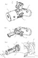
- FIG. 1 a motor vehicle steering lock 1 is shown.
- the motor vehicle steering lock 1 has an in FIG. 2 Closer cylinder 2 shown closer, in FIG. 1 is covered by a housing 3.
- the lock cylinder 2 is arranged in the cover 3 forming a housing and has a switching shaft 4, which can take different rotational positions by means of a mechanical key, when a suitable and authorized key frontally into the keyhole on the housing 3 in the rotatably mounted Lock cylinder 2 is inserted and turned.
- the switching shaft 3 is coupled for movement with an actuating element 5 of an ignition switch 6, so that a rotational movement of the switching shaft 3 upon rotation of the lock cylinder 2 leads to a rotation of the actuating element 5.
- a desired function in the motor vehicle such as the function of a power supply in the motor vehicle exclusively from the starter battery for example, the radio or the function of a power supply for ignition and engine consumers.
- FIGS. 3 to 7 In the schematic representations of FIGS. 3 to 7 is the compound of the invention switching shaft 3 and Control element 5 is shown, wherein for reasons of clarity on a representation of the remaining components of the motor vehicle steering lock 1, such as those in FIG. 1 shown steering lock 7 or the housing 3 FIG. 1 , was waived.
- FIGS. 2 to 7 are the shift shaft 4 of the lock cylinder 2 and the actuator 5 of the ignition switch 6 rotatably connected to each other via an inventive intermediate compensation element 11.
- the intermediate compensation element 11 is designed such that there is a relative movement of the switching shaft 4 to the adjusting element 5 in a radially to the longitudinal axis 8 of the switching shaft 4 extending first axial direction 9 and a relative movement of the adjusting element 5 to the selector shaft 4 in a second, perpendicular to the first Axial direction 9 extending axial direction 10 allows.
- the switching shaft 4 at its free longitudinal end 12 on a coupling lug 14, such as, for example FIG. 4 is apparent.
- the coupling lug 14 extends in the direction of the longitudinal axis 8 (see, for example FIG. 6 ) and is inserted in the assembled state of the motor vehicle steering lock 1 in a coupling receptacle 15 which is formed in the intermediate compensation element 11.
- the coupling lug 14 of the switching shaft 4 and the coupling receptacle 15 of the intermediate compensation element 11 are formed to each other such that the coupling lug 14 is inserted in the coupling receptacle 15 without play to the first axial direction 9 and movable in the second axial direction 10.
- the intermediate compensation element 11 creates a first axis freedom.
- the switching shaft 4 has a degree of freedom of movement in the first axial direction 9, wherein a freedom of movement in the direction of the longitudinal axis 8 is always given.
- a coupling approach 14 but a plurality of web-shaped projections in one or in a plurality of coupling receptacles 15 can be inserted with play in the first axial direction 9.
- the Coupling lug 14 as a central, transverse coupling web 16 at the free longitudinal end 12 of the shift shaft 4 is formed.
- the coupling receptacle 15 is formed as a coupling slot 18 which in one of the switching shaft 4 facing side surface 17 (see FIG. 7 ) of the intermediate compensation element 11 is formed.
- the coupling web 16 is fitted with clearance in the longitudinal direction 8 and in the direction of the second axial direction 10 in the coupling slot 18, so that the switching shaft 4 and thus the lock cylinder 2 in the intermediate element 11 in the first axial direction 9 and can move relative to the actuator 5.
- the coupling web 16 of the switching shaft 4 of the lock cylinder 2 and extending in the first axial direction 9 coupling slot 18 of the intermediate compensation element 11 thus ensure a degree of freedom of movement of the switching shaft 4 relative to the actuating element 5 in a spatial direction.
- the invention provides that the adjusting element 5 has a connection projection 19 which projects in the direction of the longitudinal axis 8.
- the connection projection 19 is inserted into a connection receptacle 20.
- the connection receptacle 20 is in this case formed in the intermediate compensation element 11 in such a way that the connection projection 19 is movably coupled in the second axial direction 10 and free of play to the first axial direction 9 with the intermediate compensation element 11. It is understood that more than just a single connection lug 19 can be provided, which is fitted into a single corresponding connection receptacle 20 with play in the second axial direction 10.
- the connecting lug 19 comprises two diametrically opposite connecting pins 21, which are formed on the adjusting element 5. Accordingly, the connection receptacle 20 has two in a the actuator 5 facing side surface 23 (see FIG. 6 ) of the intermediate compensation element 11 formed radial slots 22. In order to achieve the desired degree of freedom of movement, the connecting pins 21 are fitted with play in the longitudinal direction 8 and in particular with play in the direction of the second axial direction 10 in the associated radial slots 22.
- the slot-shaped configuration of the coupling receptacle 15 and the connection receptacle 20 of the intermediate compensation element 11 is helpful in order to reduce installation space in the axial direction, i. in the direction of the longitudinal axis 8, save, because as a survey on the side surfaces 17, 23 of the insects Morganselements 11 trained receptacles for the lugs 14, 19 of the switching shaft 4 and actuator 5 would extend the installation space in the direction of the longitudinal axis 8 and thus increase.
- the intermediate compensation element 11 is disc-shaped and preferably thin, wherein the coupling receptacle 15 and / or the connection receptacle 20 is formed as a respective recess in an associated side surface 17, 23 of the intermediate compensation element 11 or as a passage opening in the intermediate compensation element 11 / are.
- the receptacles 15, 20 are formed as passage openings, which is the most favorable embodiment with regard to the installation space of the motor vehicle steering lock 1.
- the switching shaft 4 could have at its free longitudinal end 12 at least one coupling recess which extends in the direction of the longitudinal axis 8.
- This coupling recess would then be a coupling approach, which on a side surface 17 of the intermediate compensation element 11 is formed, play free to the first axial direction 9 and movable in the second axial direction 10 record.
- the adjusting element 5 would then have at least one connection recess extending in the direction of the longitudinal axis 8.
- This connecting recess would accordingly receive a connecting lug movably in the first axial direction 9 and free from play to the second axial direction 10, the connecting lug being formed on a side surface 23 of the intermediate compensating element 11 opposite the coupling projection.
- backlash-free and “backlash-free” in the sense of the invention mean, using the example of the coupling approach 14, that with backlash in the first axial direction 9, a movement of the coupling attachment 14 in the first axial direction 9 is not possible.
Landscapes
- Engineering & Computer Science (AREA)
- Mechanical Engineering (AREA)
- Lock And Its Accessories (AREA)
- Power Steering Mechanism (AREA)
Claims (10)
- Verrou de direction de véhicule automobile (1), comportant un boîtier (3), dans lequel est disposé un barillet de serrure (2) avec un arbre de sélection (4), qui peut adopter différentes positions de rotation et un élément de réglage (5) d'un contacteur-démarreur (6), accouplé en mouvement à l'arbre de sélection (4) du barillet de serrure (2), qui déclenche une fonction souhaitée dans le véhicule automobile en fonction de la position de rotation de l'arbre de sélection (4),
caractérisé en ce que
l'arbre de sélection (4) du barillet de serrure (2) et l'élément de réglage (5) du contacteur-démarreur (6) sont reliés l'un à l'autre solidaire en rotation par le biais d'un élément de compensation intermédiaire (11) permettant un mouvement relatif de l'arbre de sélection (4) par rapport à l'élément de réglage (5) dans une première direction axiale (9) passant radialement à l'axe longitudinal (8) de l'arbre de sélection (4) et un mouvement relatif de l'élément de réglage (5) par rapport à l'arbre de sélection (4) dans une deuxième direction axiale (10) passant perpendiculairement à la première direction axiale (9) . - Verrou de direction de véhicule automobile (1) selon la revendication 1, caractérisé en ce que l'arbre de sélection (4) comporte à son extrémité longitudinale libre (12) au moins un téton d'accouplement (14) faisant saillie en direction de l'axe longitudinal (8), qui est inséré dans au moins un logement d'accouplement (15) conformé dans l'élément de compensation intermédiaire (11) sans jeu par rapport à la deuxième direction axiale (10) et de façon mobile dans la première direction axiale (9).
- Verrou de direction de véhicule automobile (1) selon la revendication 2, caractérisé en ce que le téton d'accouplement (14) est constitué comme une nervure d'accouplement (6) centrale, passant transversalement à l'extrémité longitudinale libre (12) de l'arbre de sélection (4) et le logement d'accouplement (15) est constitué comme une fente d'accouplement (18) conformée dans une surface latérale (17) de l'élément de compensation intermédiaire (11) tournée vers l'arbre de sélection (4), la nervure d'accouplement (16) étant emboîtée dans la fente d'accouplement (18) avec jeu en direction longitudinale (8) et en direction de la première direction axiale (9).
- Verrou de direction de véhicule automobile (1) selon l'une quelconque des revendications précédentes, caractérisé en ce que l'élément de réglage (5) comporte au moins un téton de liaison (19) faisant saillie en direction de l'axe longitudinal (8), qui est inséré dans au moins un logement de liaison (20) conformé dans l'élément de compensation intermédiaire (11) de façon mobile dans la deuxième direction axiale (10) et sans jeu par rapport à la première direction axiale (9).
- Verrou de direction de véhicule automobile (1) selon la revendication 4, caractérisé en ce que le téton de liaison (19) est constitué sur l'élément de réglage (5) sous la forme de deux tenons de liaison (21) s'opposant diamétralement et le logement de liaison (20) est constitué sous la forme de deux fentes radiales (22) conformées dans une surface latérale (23) de l'élément de compensation intermédiaire (11) tournée vers l'élément de réglage (5), les tenons de liaison (21) étant emboîtés avec jeu dans la fente radiale (22) dans la direction longitudinale (8) et dans la direction de la deuxième direction axiale (10) .
- Verrou de direction de véhicule automobile (1) selon la revendication 3 ou 5, caractérisé en ce que l'élément de compensation intermédiaire (11) est constitué en forme de rondelle, au moins un logement d'accouplement (15) et/ou au moins un logement de liaison (20) étant conformé comme évidement dans une surface latérale respective de l'élément de compensation intermédiaire (11) ou comme ouverture de passage dans l'élément de compensation intermédiaire (11) .
- Verrou de direction de véhicule automobile (1) selon la revendication 6, caractérisé en ce qu'au moins un logement d'accouplement (15) et au moins un logement de liaison (20) sont constitués sur des surfaces latérales opposées (17, 23) de l'élément de compensation intermédiaire (11) sous la forme de rainures (18, 22) déportées de 90° l'une par rapport à l'autre.
- Verrou de direction de véhicule automobile (1) selon l'une quelconque des revendications précédentes, caractérisé en ce que l'élément de compensation intermédiaire (11) est une pièce en matière plastique.
- Verrou de direction de véhicule automobile (1) selon la revendication 1, caractérisé en ce que l'arbre de sélection (4) comporte à son extrémité longitudinale libre (12) au moins une cavité d'accouplement s'étendant en direction de l'axe longitudinal (8), qui loge un téton d'accouplement conformé sur une surface latérale (17) de l'élément de compensation intermédiaire (11) sans jeu par rapport à la première direction axiale (9) et de façon mobile dans la deuxième direction axiale (10).
- Verrou de direction de véhicule automobile (1) selon la revendication 9, caractérisé en ce que l'élément de réglage (5) comporte au moins une cavité de liaison s'étendant en direction de l'axe longitudinal (8), qui loge un téton de liaison conformé sur une surface latérale (17, 23) de l'élément de compensation intermédiaire (11) opposée au tenon d'accouplement de façon mobile dans la première direction axiale (9) et sans jeu par rapport à la deuxième direction axiale (10) .
Applications Claiming Priority (2)
| Application Number | Priority Date | Filing Date | Title |
|---|---|---|---|
| DE102015111832.7A DE102015111832A1 (de) | 2015-07-21 | 2015-07-21 | Kraftfahrzeug-Lenkschloss |
| PCT/EP2016/061254 WO2017012734A1 (fr) | 2015-07-21 | 2016-05-19 | Verrou de direction de véhicule automobile |
Publications (2)
| Publication Number | Publication Date |
|---|---|
| EP3325317A1 EP3325317A1 (fr) | 2018-05-30 |
| EP3325317B1 true EP3325317B1 (fr) | 2019-04-10 |
Family
ID=56024296
Family Applications (1)
| Application Number | Title | Priority Date | Filing Date |
|---|---|---|---|
| EP16723744.5A Not-in-force EP3325317B1 (fr) | 2015-07-21 | 2016-05-19 | Verrou de direction de véhicule automobile |
Country Status (5)
| Country | Link |
|---|---|
| US (1) | US10507791B2 (fr) |
| EP (1) | EP3325317B1 (fr) |
| CN (1) | CN107848490B (fr) |
| DE (1) | DE102015111832A1 (fr) |
| WO (1) | WO2017012734A1 (fr) |
Family Cites Families (34)
| Publication number | Priority date | Publication date | Assignee | Title |
|---|---|---|---|---|
| US2462827A (en) * | 1946-10-01 | 1949-02-22 | Yale & Towne Mfg Co | Lock mechanism |
| US2691290A (en) * | 1950-07-03 | 1954-10-12 | Schlage Lock Co | Lock set |
| US2712749A (en) * | 1951-05-10 | 1955-07-12 | Nat Brass Co | Clutch and lost motion assembly for door latches |
| US2687637A (en) * | 1951-06-30 | 1954-08-31 | Briggs & Stratton Corp | Door latch operating mechanism |
| US3143874A (en) * | 1962-08-17 | 1964-08-11 | Briggs & Stratton Corp | Automobile lock having swingable shaft |
| JPS4911910B1 (fr) | 1969-12-29 | 1974-03-20 | Nissan Motor | |
| DE2058802C3 (de) * | 1970-11-30 | 1980-02-28 | Neiman & Co Kg, 5600 Wuppertal | Lenkschloß für Kraftfahrzeuge |
| US3940958A (en) * | 1973-12-22 | 1976-03-02 | Kabushiki Kaisha Honda Lock | Steering lock for vehicles |
| US4068510A (en) * | 1976-06-28 | 1978-01-17 | Schlage Lock Company | Double cylinder safety lock |
| US4228669A (en) * | 1978-07-03 | 1980-10-21 | Kysor Industrial Corporation | Double cylinder lock with key retention |
| AT381348B (de) * | 1983-10-18 | 1986-09-25 | Evva Werke | Schliesszylinder mit einer kupplungsvorrichtung sowie kupplungsvorrichtung |
| US5174136A (en) * | 1991-10-04 | 1992-12-29 | Thwing Randy L | Dual function padlock with removable cylinder mechanism |
| DE9202367U1 (de) | 1992-02-24 | 1992-04-16 | Hülsbeck & Fürst GmbH & Co KG, 5620 Velbert | Lenkschloß für Kraftfahrzeuge |
| US5363678A (en) * | 1993-04-09 | 1994-11-15 | Abus August Bremicker Sohne Kg | Padlock with ball-locked shackle |
| EP0742127B1 (fr) * | 1995-04-11 | 2002-09-11 | Tokai Rika Co., Ltd. | Dispositif de commande de démarrage pour un véhicule |
| US5931035A (en) * | 1996-02-14 | 1999-08-03 | Ortech Co. | Cylinder type lock arrangement |
| DE29611043U1 (de) | 1996-06-24 | 1996-08-29 | Hülsbeck & Fürst GmbH & Co KG, 42551 Velbert | Lenkschloß für Kraftfahrzeuge |
| US6145356A (en) * | 1999-01-11 | 2000-11-14 | Thwing; Randy L. | Dual-function locks and sub-assemblies therefor |
| DE10031249C2 (de) * | 2000-06-27 | 2002-11-28 | Huf Huelsbeck & Fuerst Gmbh | Betätigungsvorrichtung für ein Schloß, insbesondere an einem Fahrzeug |
| DE10147031B4 (de) * | 2000-09-27 | 2012-11-29 | Marquardt Gmbh | Zündschloß für ein Kraftfahrzeug |
| US6758075B1 (en) * | 2002-06-06 | 2004-07-06 | Randy L. Thwing | Conversion between lock functions using lock actuator |
| JP2004314745A (ja) * | 2003-04-15 | 2004-11-11 | Tokai Rika Co Ltd | ステアリングロック装置 |
| US6978645B2 (en) * | 2003-06-23 | 2005-12-27 | Strattec Security Corporation | Freewheeling lock apparatus and method |
| JP4358060B2 (ja) * | 2004-07-30 | 2009-11-04 | 株式会社ホンダロック | ステアリングロック装置の検査装置 |
| CN2821840Y (zh) * | 2005-06-30 | 2006-09-27 | 陈祥杰 | 一种改进型摩托车点火锁 |
| JP4712590B2 (ja) * | 2006-03-29 | 2011-06-29 | 株式会社ユーシン | ステアリングロック装置 |
| JP5500797B2 (ja) * | 2008-07-29 | 2014-05-21 | 株式会社東海理化電機製作所 | キー装置 |
| US7870772B1 (en) * | 2009-09-15 | 2011-01-18 | Eversafety Precision Industry (Tianjin) Co., Ltd | Exterior lever lock device with a clutch assembly |
| JP6000169B2 (ja) * | 2013-03-14 | 2016-09-28 | 株式会社ホンダロック | シリンダ錠 |
| CN104124093B (zh) * | 2013-04-26 | 2018-07-31 | 株式会社有信 | 转向锁定装置 |
| FR3012094B1 (fr) * | 2013-10-21 | 2016-01-01 | Shin France U | Antivol pour colonne de direction de vehicule automobile |
| JP6322470B2 (ja) * | 2014-04-25 | 2018-05-09 | 株式会社アルファ | ロータリースイッチ装置 |
| FR3026698B1 (fr) * | 2014-10-01 | 2018-05-04 | U-Shin France | Antivol pour colonne de direction de vehicule automobile |
| CN204424140U (zh) * | 2015-03-16 | 2015-06-24 | 浙江森森汽车零部件有限公司 | 汽车用带点火开关的转向锁 |
-
2015
- 2015-07-21 DE DE102015111832.7A patent/DE102015111832A1/de not_active Withdrawn
-
2016
- 2016-05-19 US US15/745,325 patent/US10507791B2/en not_active Expired - Fee Related
- 2016-05-19 EP EP16723744.5A patent/EP3325317B1/fr not_active Not-in-force
- 2016-05-19 WO PCT/EP2016/061254 patent/WO2017012734A1/fr not_active Ceased
- 2016-05-19 CN CN201680042529.7A patent/CN107848490B/zh not_active Expired - Fee Related
Non-Patent Citations (1)
| Title |
|---|
| None * |
Also Published As
| Publication number | Publication date |
|---|---|
| US20180208154A1 (en) | 2018-07-26 |
| EP3325317A1 (fr) | 2018-05-30 |
| US10507791B2 (en) | 2019-12-17 |
| CN107848490A (zh) | 2018-03-27 |
| CN107848490B (zh) | 2020-06-12 |
| DE102015111832A1 (de) | 2017-01-26 |
| WO2017012734A1 (fr) | 2017-01-26 |
Similar Documents
| Publication | Publication Date | Title |
|---|---|---|
| EP1110828B1 (fr) | Dispositif de verrouillage | |
| DE102010007913B4 (de) | Drehsteller | |
| EP2436858A2 (fr) | Cylindre de fermeture pour un verrou | |
| EP3776750B1 (fr) | Pièce de connecteur électrique et système de connexion électrique avec verrouillage | |
| EP3259802B1 (fr) | Module d'antenne | |
| EP3710344B1 (fr) | Système d'accouplement | |
| EP1715210A2 (fr) | Elément de blocage | |
| EP1971503A1 (fr) | Commutateur, notamment commutateur de colonne de direction pour véhicule automobile | |
| EP3035357A1 (fr) | Élément de commutation modulaire électromécanique | |
| EP3325317B1 (fr) | Verrou de direction de véhicule automobile | |
| DE10341136A1 (de) | Verriegelungselement für eine Steckverbindung | |
| EP2485925B1 (fr) | Dispositif d'essuie-glace | |
| EP3575637B1 (fr) | Syst?me d'entraînement de véhicule automobile | |
| EP3204581B1 (fr) | Serrure de porte de véhicule automobile | |
| EP2224832B1 (fr) | Boîtier avec un module disposé à l'intérieur | |
| EP0428029B1 (fr) | Serrure | |
| DE3031711A1 (de) | Elektrischer dreh- und zugschalter, insbesondere fuer kraftfahrzeuge | |
| EP0791707B1 (fr) | Serrure pour véhicule automobile | |
| DE102020115138A1 (de) | Baugruppe für ein Fahrzeug und Fahrzeug | |
| WO2014139891A1 (fr) | Unité d'entrée pour un élément de commande pouvant être actionné par pression et par rotation | |
| EP3837708B1 (fr) | Commutateur électrique | |
| EP1440259B1 (fr) | Dispositif de commutation pour changement de vitesse manuel | |
| DE102016122432A1 (de) | Lenkstockhebel mit Drehkopplung zwischen einem Schaltbolzen und einem Gehäuse, Lenksäulenmodul, Kraftfahrzeug und Verfahren zum Herstellen eines Lenkstockhebels | |
| AT522147A1 (de) | Schließeinrichtung | |
| DE10320660A1 (de) | Stellantrieb |
Legal Events
| Date | Code | Title | Description |
|---|---|---|---|
| STAA | Information on the status of an ep patent application or granted ep patent |
Free format text: STATUS: THE INTERNATIONAL PUBLICATION HAS BEEN MADE |
|
| PUAI | Public reference made under article 153(3) epc to a published international application that has entered the european phase |
Free format text: ORIGINAL CODE: 0009012 |
|
| STAA | Information on the status of an ep patent application or granted ep patent |
Free format text: STATUS: REQUEST FOR EXAMINATION WAS MADE |
|
| 17P | Request for examination filed |
Effective date: 20180221 |
|
| AK | Designated contracting states |
Kind code of ref document: A1 Designated state(s): AL AT BE BG CH CY CZ DE DK EE ES FI FR GB GR HR HU IE IS IT LI LT LU LV MC MK MT NL NO PL PT RO RS SE SI SK SM TR |
|
| AX | Request for extension of the european patent |
Extension state: BA ME |
|
| DAV | Request for validation of the european patent (deleted) | ||
| DAX | Request for extension of the european patent (deleted) | ||
| GRAP | Despatch of communication of intention to grant a patent |
Free format text: ORIGINAL CODE: EPIDOSNIGR1 |
|
| STAA | Information on the status of an ep patent application or granted ep patent |
Free format text: STATUS: GRANT OF PATENT IS INTENDED |
|
| INTG | Intention to grant announced |
Effective date: 20190107 |
|
| GRAS | Grant fee paid |
Free format text: ORIGINAL CODE: EPIDOSNIGR3 |
|
| GRAA | (expected) grant |
Free format text: ORIGINAL CODE: 0009210 |
|
| STAA | Information on the status of an ep patent application or granted ep patent |
Free format text: STATUS: THE PATENT HAS BEEN GRANTED |
|
| AK | Designated contracting states |
Kind code of ref document: B1 Designated state(s): AL AT BE BG CH CY CZ DE DK EE ES FI FR GB GR HR HU IE IS IT LI LT LU LV MC MK MT NL NO PL PT RO RS SE SI SK SM TR |
|
| REG | Reference to a national code |
Ref country code: GB Ref legal event code: FG4D Free format text: NOT ENGLISH |
|
| REG | Reference to a national code |
Ref country code: CH Ref legal event code: EP Ref country code: AT Ref legal event code: REF Ref document number: 1118227 Country of ref document: AT Kind code of ref document: T Effective date: 20190415 |
|
| REG | Reference to a national code |
Ref country code: IE Ref legal event code: FG4D Free format text: LANGUAGE OF EP DOCUMENT: GERMAN |
|
| REG | Reference to a national code |
Ref country code: DE Ref legal event code: R096 Ref document number: 502016004149 Country of ref document: DE |
|
| REG | Reference to a national code |
Ref country code: NL Ref legal event code: MP Effective date: 20190410 |
|
| REG | Reference to a national code |
Ref country code: LT Ref legal event code: MG4D |
|
| PG25 | Lapsed in a contracting state [announced via postgrant information from national office to epo] |
Ref country code: NL Free format text: LAPSE BECAUSE OF FAILURE TO SUBMIT A TRANSLATION OF THE DESCRIPTION OR TO PAY THE FEE WITHIN THE PRESCRIBED TIME-LIMIT Effective date: 20190410 |
|
| PG25 | Lapsed in a contracting state [announced via postgrant information from national office to epo] |
Ref country code: ES Free format text: LAPSE BECAUSE OF FAILURE TO SUBMIT A TRANSLATION OF THE DESCRIPTION OR TO PAY THE FEE WITHIN THE PRESCRIBED TIME-LIMIT Effective date: 20190410 Ref country code: SE Free format text: LAPSE BECAUSE OF FAILURE TO SUBMIT A TRANSLATION OF THE DESCRIPTION OR TO PAY THE FEE WITHIN THE PRESCRIBED TIME-LIMIT Effective date: 20190410 Ref country code: AL Free format text: LAPSE BECAUSE OF FAILURE TO SUBMIT A TRANSLATION OF THE DESCRIPTION OR TO PAY THE FEE WITHIN THE PRESCRIBED TIME-LIMIT Effective date: 20190410 Ref country code: NO Free format text: LAPSE BECAUSE OF FAILURE TO SUBMIT A TRANSLATION OF THE DESCRIPTION OR TO PAY THE FEE WITHIN THE PRESCRIBED TIME-LIMIT Effective date: 20190710 Ref country code: HR Free format text: LAPSE BECAUSE OF FAILURE TO SUBMIT A TRANSLATION OF THE DESCRIPTION OR TO PAY THE FEE WITHIN THE PRESCRIBED TIME-LIMIT Effective date: 20190410 Ref country code: PT Free format text: LAPSE BECAUSE OF FAILURE TO SUBMIT A TRANSLATION OF THE DESCRIPTION OR TO PAY THE FEE WITHIN THE PRESCRIBED TIME-LIMIT Effective date: 20190910 Ref country code: FI Free format text: LAPSE BECAUSE OF FAILURE TO SUBMIT A TRANSLATION OF THE DESCRIPTION OR TO PAY THE FEE WITHIN THE PRESCRIBED TIME-LIMIT Effective date: 20190410 Ref country code: LT Free format text: LAPSE BECAUSE OF FAILURE TO SUBMIT A TRANSLATION OF THE DESCRIPTION OR TO PAY THE FEE WITHIN THE PRESCRIBED TIME-LIMIT Effective date: 20190410 |
|
| PG25 | Lapsed in a contracting state [announced via postgrant information from national office to epo] |
Ref country code: LV Free format text: LAPSE BECAUSE OF FAILURE TO SUBMIT A TRANSLATION OF THE DESCRIPTION OR TO PAY THE FEE WITHIN THE PRESCRIBED TIME-LIMIT Effective date: 20190410 Ref country code: BG Free format text: LAPSE BECAUSE OF FAILURE TO SUBMIT A TRANSLATION OF THE DESCRIPTION OR TO PAY THE FEE WITHIN THE PRESCRIBED TIME-LIMIT Effective date: 20190710 Ref country code: RS Free format text: LAPSE BECAUSE OF FAILURE TO SUBMIT A TRANSLATION OF THE DESCRIPTION OR TO PAY THE FEE WITHIN THE PRESCRIBED TIME-LIMIT Effective date: 20190410 Ref country code: GR Free format text: LAPSE BECAUSE OF FAILURE TO SUBMIT A TRANSLATION OF THE DESCRIPTION OR TO PAY THE FEE WITHIN THE PRESCRIBED TIME-LIMIT Effective date: 20190711 Ref country code: PL Free format text: LAPSE BECAUSE OF FAILURE TO SUBMIT A TRANSLATION OF THE DESCRIPTION OR TO PAY THE FEE WITHIN THE PRESCRIBED TIME-LIMIT Effective date: 20190410 |
|
| REG | Reference to a national code |
Ref country code: CH Ref legal event code: PL |
|
| PG25 | Lapsed in a contracting state [announced via postgrant information from national office to epo] |
Ref country code: IS Free format text: LAPSE BECAUSE OF FAILURE TO SUBMIT A TRANSLATION OF THE DESCRIPTION OR TO PAY THE FEE WITHIN THE PRESCRIBED TIME-LIMIT Effective date: 20190810 |
|
| REG | Reference to a national code |
Ref country code: DE Ref legal event code: R097 Ref document number: 502016004149 Country of ref document: DE |
|
| PG25 | Lapsed in a contracting state [announced via postgrant information from national office to epo] |
Ref country code: CH Free format text: LAPSE BECAUSE OF NON-PAYMENT OF DUE FEES Effective date: 20190531 Ref country code: MC Free format text: LAPSE BECAUSE OF FAILURE TO SUBMIT A TRANSLATION OF THE DESCRIPTION OR TO PAY THE FEE WITHIN THE PRESCRIBED TIME-LIMIT Effective date: 20190410 Ref country code: DK Free format text: LAPSE BECAUSE OF FAILURE TO SUBMIT A TRANSLATION OF THE DESCRIPTION OR TO PAY THE FEE WITHIN THE PRESCRIBED TIME-LIMIT Effective date: 20190410 Ref country code: SK Free format text: LAPSE BECAUSE OF FAILURE TO SUBMIT A TRANSLATION OF THE DESCRIPTION OR TO PAY THE FEE WITHIN THE PRESCRIBED TIME-LIMIT Effective date: 20190410 Ref country code: LI Free format text: LAPSE BECAUSE OF NON-PAYMENT OF DUE FEES Effective date: 20190531 Ref country code: EE Free format text: LAPSE BECAUSE OF FAILURE TO SUBMIT A TRANSLATION OF THE DESCRIPTION OR TO PAY THE FEE WITHIN THE PRESCRIBED TIME-LIMIT Effective date: 20190410 Ref country code: RO Free format text: LAPSE BECAUSE OF FAILURE TO SUBMIT A TRANSLATION OF THE DESCRIPTION OR TO PAY THE FEE WITHIN THE PRESCRIBED TIME-LIMIT Effective date: 20190410 Ref country code: CZ Free format text: LAPSE BECAUSE OF FAILURE TO SUBMIT A TRANSLATION OF THE DESCRIPTION OR TO PAY THE FEE WITHIN THE PRESCRIBED TIME-LIMIT Effective date: 20190410 |
|
| REG | Reference to a national code |
Ref country code: BE Ref legal event code: MM Effective date: 20190531 |
|
| PLBE | No opposition filed within time limit |
Free format text: ORIGINAL CODE: 0009261 |
|
| STAA | Information on the status of an ep patent application or granted ep patent |
Free format text: STATUS: NO OPPOSITION FILED WITHIN TIME LIMIT |
|
| PG25 | Lapsed in a contracting state [announced via postgrant information from national office to epo] |
Ref country code: SM Free format text: LAPSE BECAUSE OF FAILURE TO SUBMIT A TRANSLATION OF THE DESCRIPTION OR TO PAY THE FEE WITHIN THE PRESCRIBED TIME-LIMIT Effective date: 20190410 Ref country code: LU Free format text: LAPSE BECAUSE OF NON-PAYMENT OF DUE FEES Effective date: 20190519 Ref country code: IT Free format text: LAPSE BECAUSE OF FAILURE TO SUBMIT A TRANSLATION OF THE DESCRIPTION OR TO PAY THE FEE WITHIN THE PRESCRIBED TIME-LIMIT Effective date: 20190410 |
|
| 26N | No opposition filed |
Effective date: 20200113 |
|
| PG25 | Lapsed in a contracting state [announced via postgrant information from national office to epo] |
Ref country code: TR Free format text: LAPSE BECAUSE OF FAILURE TO SUBMIT A TRANSLATION OF THE DESCRIPTION OR TO PAY THE FEE WITHIN THE PRESCRIBED TIME-LIMIT Effective date: 20190410 |
|
| PG25 | Lapsed in a contracting state [announced via postgrant information from national office to epo] |
Ref country code: IE Free format text: LAPSE BECAUSE OF NON-PAYMENT OF DUE FEES Effective date: 20190519 |
|
| PG25 | Lapsed in a contracting state [announced via postgrant information from national office to epo] |
Ref country code: SI Free format text: LAPSE BECAUSE OF FAILURE TO SUBMIT A TRANSLATION OF THE DESCRIPTION OR TO PAY THE FEE WITHIN THE PRESCRIBED TIME-LIMIT Effective date: 20190410 Ref country code: BE Free format text: LAPSE BECAUSE OF NON-PAYMENT OF DUE FEES Effective date: 20190531 |
|
| GBPC | Gb: european patent ceased through non-payment of renewal fee |
Effective date: 20200519 |
|
| PG25 | Lapsed in a contracting state [announced via postgrant information from national office to epo] |
Ref country code: GB Free format text: LAPSE BECAUSE OF NON-PAYMENT OF DUE FEES Effective date: 20200519 |
|
| PG25 | Lapsed in a contracting state [announced via postgrant information from national office to epo] |
Ref country code: CY Free format text: LAPSE BECAUSE OF FAILURE TO SUBMIT A TRANSLATION OF THE DESCRIPTION OR TO PAY THE FEE WITHIN THE PRESCRIBED TIME-LIMIT Effective date: 20190410 |
|
| PG25 | Lapsed in a contracting state [announced via postgrant information from national office to epo] |
Ref country code: MT Free format text: LAPSE BECAUSE OF FAILURE TO SUBMIT A TRANSLATION OF THE DESCRIPTION OR TO PAY THE FEE WITHIN THE PRESCRIBED TIME-LIMIT Effective date: 20190410 Ref country code: HU Free format text: LAPSE BECAUSE OF FAILURE TO SUBMIT A TRANSLATION OF THE DESCRIPTION OR TO PAY THE FEE WITHIN THE PRESCRIBED TIME-LIMIT; INVALID AB INITIO Effective date: 20160519 |
|
| PGFP | Annual fee paid to national office [announced via postgrant information from national office to epo] |
Ref country code: DE Payment date: 20210531 Year of fee payment: 6 Ref country code: FR Payment date: 20210521 Year of fee payment: 6 |
|
| PG25 | Lapsed in a contracting state [announced via postgrant information from national office to epo] |
Ref country code: MK Free format text: LAPSE BECAUSE OF FAILURE TO SUBMIT A TRANSLATION OF THE DESCRIPTION OR TO PAY THE FEE WITHIN THE PRESCRIBED TIME-LIMIT Effective date: 20190410 |
|
| REG | Reference to a national code |
Ref country code: AT Ref legal event code: MM01 Ref document number: 1118227 Country of ref document: AT Kind code of ref document: T Effective date: 20210519 |
|
| PG25 | Lapsed in a contracting state [announced via postgrant information from national office to epo] |
Ref country code: AT Free format text: LAPSE BECAUSE OF NON-PAYMENT OF DUE FEES Effective date: 20210519 |
|
| REG | Reference to a national code |
Ref country code: DE Ref legal event code: R119 Ref document number: 502016004149 Country of ref document: DE |
|
| PG25 | Lapsed in a contracting state [announced via postgrant information from national office to epo] |
Ref country code: FR Free format text: LAPSE BECAUSE OF NON-PAYMENT OF DUE FEES Effective date: 20220531 |
|
| PG25 | Lapsed in a contracting state [announced via postgrant information from national office to epo] |
Ref country code: DE Free format text: LAPSE BECAUSE OF NON-PAYMENT OF DUE FEES Effective date: 20221201 |