EP3325732B1 - Modul zum zusammebau einer wand, die aus paletten besteht und herstellungsverfahren für solch eine wand - Google Patents
Modul zum zusammebau einer wand, die aus paletten besteht und herstellungsverfahren für solch eine wand Download PDFInfo
- Publication number
- EP3325732B1 EP3325732B1 EP16742300.3A EP16742300A EP3325732B1 EP 3325732 B1 EP3325732 B1 EP 3325732B1 EP 16742300 A EP16742300 A EP 16742300A EP 3325732 B1 EP3325732 B1 EP 3325732B1
- Authority
- EP
- European Patent Office
- Prior art keywords
- pallets
- pallet
- vertical
- module
- horizontal
- Prior art date
- Legal status (The legal status is an assumption and is not a legal conclusion. Google has not performed a legal analysis and makes no representation as to the accuracy of the status listed.)
- Active
Links
Images


Classifications
-
- E—FIXED CONSTRUCTIONS
- E04—BUILDING
- E04B—GENERAL BUILDING CONSTRUCTIONS; WALLS, e.g. PARTITIONS; ROOFS; FLOORS; CEILINGS; INSULATION OR OTHER PROTECTION OF BUILDINGS
- E04B1/00—Constructions in general; Structures which are not restricted either to walls, e.g. partitions, or floors or ceilings or roofs
- E04B1/02—Structures consisting primarily of load-supporting, block-shaped, or slab-shaped elements
- E04B1/10—Structures consisting primarily of load-supporting, block-shaped, or slab-shaped elements the elements consisting of wood
-
- E—FIXED CONSTRUCTIONS
- E04—BUILDING
- E04C—STRUCTURAL ELEMENTS; BUILDING MATERIALS
- E04C1/00—Building elements of block or other shape for the construction of parts of buildings
-
- E—FIXED CONSTRUCTIONS
- E04—BUILDING
- E04C—STRUCTURAL ELEMENTS; BUILDING MATERIALS
- E04C2/00—Building elements of relatively thin form for the construction of parts of buildings, e.g. sheet materials, slabs, or panels
- E04C2/02—Building elements of relatively thin form for the construction of parts of buildings, e.g. sheet materials, slabs, or panels characterised by specified materials
- E04C2/10—Building elements of relatively thin form for the construction of parts of buildings, e.g. sheet materials, slabs, or panels characterised by specified materials of wood, fibres, chips, vegetable stems, or the like; of plastics; of foamed products
- E04C2/12—Building elements of relatively thin form for the construction of parts of buildings, e.g. sheet materials, slabs, or panels characterised by specified materials of wood, fibres, chips, vegetable stems, or the like; of plastics; of foamed products of solid wood
-
- E—FIXED CONSTRUCTIONS
- E04—BUILDING
- E04B—GENERAL BUILDING CONSTRUCTIONS; WALLS, e.g. PARTITIONS; ROOFS; FLOORS; CEILINGS; INSULATION OR OTHER PROTECTION OF BUILDINGS
- E04B1/00—Constructions in general; Structures which are not restricted either to walls, e.g. partitions, or floors or ceilings or roofs
- E04B1/38—Connections for building structures in general
- E04B1/61—Connections for building structures in general of slab-shaped building elements with each other
- E04B1/6108—Connections for building structures in general of slab-shaped building elements with each other the frontal surfaces of the slabs connected together
- E04B1/612—Connections for building structures in general of slab-shaped building elements with each other the frontal surfaces of the slabs connected together by means between frontal surfaces
- E04B1/6145—Connections for building structures in general of slab-shaped building elements with each other the frontal surfaces of the slabs connected together by means between frontal surfaces with recesses in both frontal surfaces co-operating with an additional connecting element
-
- E—FIXED CONSTRUCTIONS
- E04—BUILDING
- E04H—BUILDINGS OR LIKE STRUCTURES FOR PARTICULAR PURPOSES; SWIMMING OR SPLASH BATHS OR POOLS; MASTS; FENCING; TENTS OR CANOPIES, IN GENERAL
- E04H17/00—Fencing, e.g. fences, enclosures, corrals
- E04H17/14—Fences constructed of rigid elements, e.g. with additional wire fillings or with posts
- E04H17/1404—Fences constructed of rigid elements, e.g. with additional wire fillings or with posts using building blocks, e.g. from concrete or stone
Definitions
- the invention belongs to the field of construction of walls for the realization of buildings in particular of buildings of the type habitats, shelters, walls, ramparts or fences.
- the invention relates to modules for assembling pallets for the production of walls, a wall and an assembly of walls produced by assembling handling pallets and a method of producing walls and wall assemblies by means of handling pallets.
- prefabricated solutions have been developed in which the building structures are produced by elements of large dimensions.
- prefabricated solutions use elements of dimensions and shapes adapted to be assembled according to a precise plan and form the building for which these elements are designed. Prefabricated elements can be produced, most often in concrete or wood, in a production plant at reduced costs and can be assembled quickly on the site where the building is erected.
- the international patent application WO 2009/062215 describes how to make the structure of a house with pallets assembled in rows and columns to form the structure of the walls and floor of the house.
- the walls are formed thick by a stack of three pallets and various materials, in particular panels and insulation.
- the pallets are assembled, with the edges in a vertical position in the partitions and walls, by metal through pieces provided with end plates which on the one hand maintain the spacing of the pallets to the thickness of the wall and fix the pallets by points or screws through the plates.
- One drawback of this arrangement is the number of fastening elements which are used, at least one at each pallet angle, and the need to fix the plates to the external pallets through the wall in progress.
- the present invention provides a solution to the problems of the prior art by making it possible to produce a wall or a wall by assembling pallets without complex means, in particular due to the unitary manipulation of the pallets during assembly and of assembly modules guaranteeing the maintenance and stability of the pallets as they are assembled.
- Such a horizontal module makes it possible to block movements between two pallets juxtaposed in the same row of pallets forming a partition frame.
- all or part of the protrusions comprises at least one orifice passing through the horizontal module (MH). It is thus avoided that the module does not form an obstacle between two pallets when it is desired to fix pipes or ducts running vertically inside a partition.
- the height dimensions (Hpr) of the protrusions are between 5 mm and a sole width, preferably between 5 mm and 50% of the width of a sole. Pallets engaged on such a horizontal module are thus kept sufficiently stable to carry out the assembly of the pallets.
- each end of a horizontal module comprises a tenon and mortise assembly to ensure the interlocking of two aligned horizontal modules.
- the positioning of juxtaposed horizontal modules is thus simpler to carry out and more precise.
- the plate comprises, between two neighboring protuberances, at least one blocking mortise, that is to say a mortise whose shape ensures that a post of complementary shape is maintained. It is thus possible, when several pallets form the thickness of the framework of a partition, to hold together and at a given distance two pallets one against the other.
- the plate has protuberances on each of its first and second faces. It is thus a horizontal module that can be placed between two superimposed rows of pallets whose protuberances cooperate with the pallets of the lower row for the protuberances placed under the plate and with the pallets of the upper row for the protuberances placed above the plate.
- the plate comprises holes or pre-holes for the placement of fixations of the plate with pallets and or with another plate of horizontal module. This ensures precise positions of the fasteners useful for assembling the frame and the possibility of installing the fasteners without drilling.
- Such a vertical module makes it possible to block the movements between two superimposed pallets in two rows of superimposed pallets forming a partition frame.
- the width (Emv) of a slot is between 30% and 80% of a depth of a pallet channel and in which the height (Hc) of a slot is less than or equal to a depth of a pallet channel.
- the base has holes or pre-holes for the placement of fastenings of said base with pallets and or with another base of vertical module.
- two pallets juxtaposed in a row are immobilized together by at least one horizontal module (MH) of assembly according to claim 1 cooperating on a long side of each of said pallets juxtaposed by protuberances, integral a sole of said horizontal module, cooperating with openings formed on the long sides of each of said pallets between two successive dice, an edge and a sole.
- MH horizontal module
- vertically superimposed pallets are immobilized together by at least one vertical assembly module (MV) according to claim 7, cooperating on a short side of each of said superimposed pallets, by slots, integral with a base of said vertical module, cooperating with channels opening out on the short sides of each of said pallets between two successive dice secured to a crosspiece.
- MV vertical assembly module
- the horizontal modules (MH) conform to the horizontal modules of the invention.
- the vertical modules (MV) conform to the vertical modules of the invention.
- a thickness of the framework comprises at least two pallets, and in the framework at least two facing pallets are arranged with their external faces facing each other. It is thus left accessible, during assembly, the volumes in the thickness of the pallets.
- the wall has, in a thickness, pallets forming the framework of the wall of sheaths and / or conduits and or insulation materials.
- the wall comprises on at least one visible face of the framework one or more panels fixed to the pallets.
- a rampart comprises at least two walls conforming to the walls of the invention arranged substantially parallel with the internal faces of pallets facing said walls facing each other.
- a separation distance (Ds) between two facing pallets is maintained in the rampart at a value chosen by at least one spacer module formed in a panel and comprising notches arranged on said spacer module to be engaged, in a position of said spacer module substantially vertical and substantially perpendicular to the internal faces of said pallets, in the soles of said pallets facing each other.
- two facing pallets are kept apart by four spacer modules distributed in two spacer modules superimposed at each end of said two facing pallets.
- This arrangement allows a reinforced connection between two facing pallets and a better resistance to the forces which could tend to bring the said pallets closer or further apart, connection which can be further reinforced by increasing the number of spacer modules.
- the volume formed between the two walls is filled, at least partially, with a filling material.
- the mass of the filling material naturally stabilizes the rampart and depending on the specific characteristics of the filling material provides protection against external aggressions, for example protection against ballistic objects, against noise, against rising water.
- fixings are placed during assembly to fix the modules, horizontal and or vertical, to the pallets of the frame or between them.
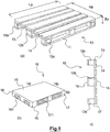
- FIG 1 perspective view (a) and side view (c) with a width Hp in a vertical position, represents an example of a wooden handling pallet 10 of a current model.
- a wooden handling pallet 10 of a current model Such a pallet, in its original application, makes it possible to ensure the handling of goods under optimal handling conditions with standard means, for example forklifts, stackers or pallet trucks.
- a dimension, taken in a longitudinal direction of the crosspieces, of a dice 12b associated with the central sole is greater than that corresponding to the dice 12a associated with the lateral flanges of the pallet, according to the EPAL standard.
- Pallet 10 is therefore inscribed in a rectangular parallelepiped, as illustrated in view (b) of the figure 1 , of dimensions Lp, Hp and Ep.
- each long side 17 it is formed between a sole and a bank and between the dice fixed to the sole two openings 171.
- the openings 171 are reproduced at each sole.
- each of said channels being formed between two neighboring flanges and open towards the internal face.
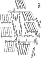
- a wall 100 for example a wall or a partition, a partial embodiment of which is illustrated in FIG. 2, a plurality of pallets 10 will be used.
- the number of pallets to be used depends on the developed surface of the wall to be produced, in particular its length and height, if necessary after deduction of the openings in the wall, and considering a number of pallets which must constitute a thickness of the wall.
- the number of pallets forming the wall thickness is at least 1, as in the example illustrated on the figure 2 , and has no theoretical maximum. In practice, the number of pallets forming the thickness of the wall will be adapted to the requirements of loads to be supported by the wall.
- the walls forming the walls will be two pallets thick, as in the examples illustrated on the Figures 12a and 12b , or three pallets as on the example of arrangement illustrated figure 13 .
- a light construction such as a shelter can be formed with walls whose thickness is only determined by a single pallet and on the contrary a multi-storey building can, in the lower parts at least, have walls whose thicknesses will be the result of an assembly of more than two pallets.
- assembly modules are used.
- the role of an assembly module is to form an interface for assembling at least two pallets and to immobilize the pallets between them in a desired position, at least for the needs of a step of assembling a wall frame 100.
- the pallets 10 are assembled to form a wall 100 with the horizontal edges 14 and therefore with the dimension Hp of the pallet along a height of said wall.
- a wall 100 comprises at least one row of pallets and generally comprises several superimposed rows to reach a desired height of said wall as illustrated by figures 2 , 6a and 6b .
- the horizontal modules MH in an assembled partition, cooperate with the long sides 17 of the pallets, and are placed in a horizontal plane.
- the vertical modules MV in an assembled partition, cooperate with the short sides 18 of the pallets, and are placed in a vertical plane.
- a horizontal module MH provides a connection between at least two pallets juxtaposed in a row of pallets.
- a horizontal module MH is a unitary element corresponding to an arrangement of several full or hollow volumes.
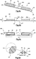
- FIG. 8a An example of a horizontal MH module is presented, in a horizontal installation position, on the figure 8a in a perspective representation, on the figure 8b in profile view, on the figure 8c in top view, and on the figure 8d in vertical section.
- the horizontal module MH des Figures 8a, 8b and 8c comprises a plate 21 substantially of length Lp, length of a pallet 10, and of a width lmh corresponding substantially to a height Ep of a pallet 10.
- the length Lp of a horizontal module is a reference length so that the juxtaposed horizontal modules have, at least in certain embodiments, overlapping in the direction length by interlocking tenons 29 with mortises 29 'at the ends of said horizontal module.
- the width lmh of a horizontal module slightly deviates from the height Ep of a pallet so that the horizontal module is reversible while remaining contained between the planes of the external 15 and internal 16 faces of the pallets.
- the horizontal module MH comprises a first substantially flat face 22 and a second face 23 comprising two protrusions 24.
- Each protuberance 24, in the embodiment illustrated in the Figures 8a, 8b, 8c , has the shape of a rectangular parallelepiped assembly.
- a width Bpr and a length Apr of the protuberance correspond respectively, for said width, to a height of the opening 171 on a long side 17 of a pallet 10 and, for said length, to the length of said opening on said side long, with tolerances on the dimensions of said protrusions such that the protrusion fits without excessive play or effort into an opening 171, including in the case where said opening has the smallest dimensions due to the manufacturing tolerances of the pallets.
- the parallelepiped shape of the protuberance may include softened edges or chamfers 241, as illustrated in the enlarged detail of the figure 8d , which will facilitate the fitting of the protuberance 24 into the opening 171 of a pallet during the assembly of a partition 100.
- a separation distance Spr between the two protrusions 24 of a horizontal module MH is also equal to twice the dimension of a die 12a, associated with a lateral flange, along the length of a pallet 10.
- This separation distance Spr results in particular from the desired position of a horizontal module MH straddling two juxtaposed pallets 10, a situation in which the dice 12a adjacent to the two pallets are also juxtaposed.
- the horizontal module MH comprises the right tenon 29 over one half of the width of the plate 21, the other half of said width corresponding to the mortise 29 ′, the straight tenons 29 being offset, in order to above said plate, to allow an interlocking at each end of the horizontal module of an identical horizontal module and so that it results in a distance between the neighboring protrusions of two juxtaposed horizontal modules equal to the dimension of a median die according to the length of a pallet 10.
- the straight shape of the right post 29 is not compulsory, but it ensures the reversible mounting of the horizontal module MH and leaves a degree of freedom in a longitudinal direction of said module to take into account the need to catch up, during the assembly of a partition frame, the dispersions over the lengths Lp of the pallets.
- At least one through hole 25 is arranged in the horizontal module MH so as to ensure a passage between the first face 22 and the second face 23 of said horizontal module.
- the through holes are located on the horizontal module so that said through holes communicate the openings 171 of two pallets 10 superimposed and immobilized together by said horizontal module.
- a through orifice is therefore located in a part of the plate 21 affected by the protrusions 24.
- a through hole 25 is made in each of the protrusions 24.
- a single through hole 25 is shown in the figures for each of the protrusions, it is also possible to make a plurality of through holes of reduced sections, for example in the purpose of obtaining a more rigid horizontal module than in the case of a single through hole of large dimensions or to ensure physical separation of conduits or ducts which must travel vertically in the partition.
- the dimensions according to the thickness of the horizontal modules MH can vary in relatively large proportions without major consequences on the functions provided by said horizontal modules.
- the thicknesses will be adapted to the material in which the modules are made to ensure the passage of the forces to which they are subjected in the considered pallet assemblies.
- a thickness Hpl of the plate 21 will be sufficient to transmit the shearing forces in the longitudinal and transverse directions when the pallets, in which the protrusions 24 are embedded, are themselves subjected to forces, for example forces induced by winds. on the wall made or in progress.
- horizontal modules MH formed in a material based on compressed and bonded wood fibers, or in a rigid cellular foam, by for example a dense polyurethane foam or an expanded polystyrene, have plates with a thickness Hpl of the order of 0.5 to 5 centimeters suitable for the production of many types of walls.
- the use of the materials and thicknesses mentioned makes it possible to have lightweight and sufficiently resistant modules when they are put in place, which can be cut, for example for cutting to length, with ordinary cutting tools, saws or sharp blades. , and allows local irregularities to absorb irregularities on the edges of the pallets, irregularities linked to the materials used for said pallets, generally rough sawn wood.
- the heights Hpr must also be sufficient to avoid accidental dislocation of the pallets, in particular during the mounting of a wall, for example a height Hpr is between 3 and 5 cm. In practice, the heights Hpr need not be substantially greater than the widths of the edges 14 or of the flanges 11.
- the protrusions 24 are made of all durable and economically acceptable materials, advantageously in the same type of material as the plate 21 with which they are associated.
- the protrusions 24 can be produced separately from the plate 21 and then added by gluing, interlocking or any other fixing means.
- the horizontal modules MH, plates 21 and associated protrusions 24, are formed integrally from the same material by cutting from a block, or by molding, or by forming directly to the desired shape.
- a vertical MV module provides a connection between at least two pallets superimposed at the ends of the walls, as illustrated in the figure 2 , or when a wall forms an angle or is extended, as illustrated on the Figures 6a and 6b , or when a wall arises on one face of another wall, case not illustrated.
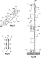
- a vertical MV module as illustrated in a vertical implementation position on the figure 9a in perspective view, the figure 9b in profile view and the figure 9c in front view, is in the form of a part of substantially constant thickness Emv comprising a base 31 and three slots 32.
- the thickness Emv is preferably less than a height of the pallet Ep reduced by a thickness of the cross member 13 and a thickness of the edge 14, that is to say less than a depth of the channels 181 in the form of U d 'a pallet.
- the thickness Emv is in practice chosen so that, when the vertical module is engaged on a vertical edge of the wall produced with pallets, said vertical module is contained between planes of the external 15 and internal faces 16 of the pallets and preferably without completely close the ends of the channels 181.
- each end of the vertical module MV comprises a straight tenon associated with a mortise which makes it possible during a abutment of two vertical modules MV to facilitate its precise juxtaposition .
- a total height Hmv of the vertical module MV is substantially equal to 1.5 times a width Hp of the pallet.
- a height Hc of each of the slots 32 is equal to an empty distance between two dice 12a, 12b over the width Lp of a pallet, that is to say a dimension of the channels 181 according to the direction of the width Hp of a pallet.
- a distance between a first end 311 of the vertical module MV and the slot 32 closest to said first end is equal to one dimension Hdla, along the width of a pallet 10, of a lateral die 12a.
- a distance between the niche 32 closest to the first end 311 and the nearest niche is equal to one dimension Hdlb, along the width of a pallet 10, of a median die 12b.
- a distance between a second end 312 of the vertical module MV and the slot 32 closest to said second end is equal to 0.5 times a dimension Hdlb, along the width of a pallet 10, of a median die 12.
- a distance between the niche 32 closest to the second end 312 and the closest preceding niche is equal to twice a dimension Hdla of a median die 12a along the width of a pallet 10, increased by twice the thickness Hpl of the plate 21 of a horizontal module MH.
- a vertical module MV can be engaged in the ends of the channels 181 at a wall end on a short side 18 of the pallets forming the wall considered, that is to say on the edge of said wall and of the pallets, as illustrated for example on the figures 2 and 6a .
- the vertical module MV can also be engaged on the internal face 16 of the pallets, provided that a width Lc of the slots, that is to say a distance between a top of said slots and the base 31, is at most equal, and preferably less, than the depth of the U-shaped channels 181 in which said slots engage, as visible on the figure 6a .
- the width Lc of the slots is at least substantially equal to the thickness Emv of said vertical modules.
- the width Lc of the slots and the thickness Emv of said vertical modules are each substantially less than the depth of the channels 181 so that said channels are not completely closed by the slots to maintain between the vertical module MV and one of the sides of the pallet a free space through which pipes or ducts passing through the wall can pass.
- MV vertical modules are made with materials and manufacturing techniques similar to those that can be used to produce horizontal MH modules.
- protrusions 24 and the slots 32 intended to be placed in openings 171 or channels 181 of the pallets, will be produced in consideration of the smallest dimensions accepted for said openings and said channels taking into account manufacturing tolerances.
- protrusions 24 or the slots 32 will be produced with separation distances between said protrusions and between said slots taking into account the largest dimensions accepted for the dice 12a, 12b, which are inserted between said protrusions or said slots.
- the assembly is carried out on a suitable floor 99, prepared in advance during a step prior to the assembly of the walls, for example on a concrete or stone foundation or on a screed depending on the type of construction provided.
- a first row 41 of horizontal connection modules MH is placed, at the desired location of a wall on the floor 99, placed on the floor at the desired location of a wall, as illustrated on the figure 3 .
- the horizontal modules MH of this first row 41 are placed juxtaposed with their first faces 22 resting on the ground and the protrusions 24 upwards.
- the horizontal modules MH of this first row 41 are placed juxtaposed along their lengths without intermediate space, respecting the engagement of the tenons 29 with the mortises 29 ′, when horizontal modules are implemented being provided with tenons and mortises , so as to form a line of a length corresponding to a number of pallets in a first row 51 of pallets, it being taken into account that a vertical separation line between two aligned juxtaposed pallets is always located on the same horizontal module MH.
- the horizontal modules MH of the first row 41 are fixed to the ground 99, for example by elements for fixing to the ground, screws or bolts not shown, if necessary with the interposition according to the rules of the art of a protective layer against rising damp which could lead to rapid deterioration of moisture-sensitive elements.
- pallets 10 are placed in a vertical position as illustrated on the figure 4 , to form a first row 51 of pallets.
- Each pallet 10 is placed with the horizontal edges 14 and, at least with a horizontal module MH comprising only two protrusions 24, so that the two openings 171 on one long side of a given pallet are each engaged by a protuberance 24 of two different MH horizontal modules.
- horizontal modules MH are placed on a free upper edge of the pallets of the first row 51 to form a second row 42 of horizontal modules MH, as illustrated in the figure 5 .
- the second row 42 of horizontal modules MH is placed in a mirror of the first row 41, that is to say with their second faces 22 and the protrusions 24 oriented downward, the said protrusions engaged in the openings 171 on the edges of the pallets and each horizontal module on horseback on two pallets.
- This second row 42 of horizontal modules makes it possible to immobilize between them, in their upper parts, the pallets of the first row 51, already immobilized in their lower parts, and the first faces 22 of said horizontal modules, oriented upwards, form a surface to place a new row of pallets on the first.
- horizontal modules MH are placed on the surface formed by the second row 42 to form a third row 43 of horizontal modules MH, as illustrated in the figure 2 .
- This third row 43 is similar to the first row 41, the horizontal modules MH being placed with their first faces 22 resting on the second row 42 and with the protrusions 24 upwards.
- the horizontal modules MH of the third row 43 are also fixed to the horizontal modules of the second row 42 so as to avoid any displacement, in particular sliding, of the horizontal modules of the third row during and after the following stages of the process.
- the third row horizontal modules can be fixed by any suitable means, in particular by fixing elements, for example screws, and or by gluing.
- the third row horizontal modules can be attached after the second row of horizontal modules have been installed. They can also be fixed before installing the second row 42 to form double horizontal modules placed in one piece.
- the horizontal modules MH comprise holes or pre-holes 26 for the placement of screws, bolts or other fasteners, and allow simple and precise positioning of two horizontal modules MH sole against sole.
- steps two, three and four are performed again for each row of pallets, as illustrated in the figure 2 , to be mounted until the number of rows and the desired height for partition 100 are reached.
- the fourth step is not necessarily carried out, which may prove to be useless in the absence of a new row of pallets to be laid.
- the figure 10 illustrates the result of an assembly according to the method of two pallets superimposed in a partition, according to a vertical section made between dice.
- vertical modules MV are placed at the ends of the wall 100 with the slots 32 engaged in the channels 181 of the pallets 10 or on the edge 18 of the pallets, as visible on the Figures 5 and 2 , either on the face internal 16 of the pallets, according to a need for angle mounting of pallets in a partition having an angle, as visible on the Figures 6a and 6b .
- the vertical modules MV of each of the partitions or parts of partition forming the angle, are assembled together, for example by screws or bolts, to form a connection stable partitions.
- each vertical module MV comprises in the base 31 holes or pre-holes 36 for fixing the vertical modules to each other and to the pallets by fastening elements, for example screws being taken up on the dice 12a, 12b of the pallets.
- accessory elements such as water pipes or electrical conduits are laid as much as desired in the thickness of the pallets.
- the method of installing the pallets makes it possible to have horizontal channels 181 open on a face opposite the banks 14 and aligned over the entire length of the partition. It is therefore possible to set up pipes or ducts simply, after mounting the frame, without having to pass through openings except, if necessary, at the ends of the wall.
- the presence of the through orifices 25 of the horizontal modules MH also bring the openings 171 of the superimposed pallets into vertical communication, which also makes it possible to place conduits, sheaths or other accessories in the vertical direction of the wall.
- the limited dimensions of the slots relative to the depth of the channels 181, for example with the thickness dimensions Emv of the order of 50% of said depth of the channels, ensure the formation of free passages in the angles.
- the reduced thickness dimension Emv relative to the depth of the channels also leaves a free passage when vertical modules are implemented in aligned pallet junctions as in the example illustrated on the figure 7
- Thermal insulating products 52 and or phonic insulating products are where appropriate placed in filling of the interior space of the pallets and covering panels 50a, 50b are fixed to the pallets in a conventional manner on one or each of the faces of the wall, as much for their finishing roles as for their participation in the rigidity and solidity of the wall.
- the covering panels 50a, 50b are for example wood panels, plywood or reconstituted wood, or plaster panels. They constitute with the framework formed by the pallets a structure of the wall.
- the assembly modules and the method are also suitable for mounting walls forming angles between them, straight or not.
- FIGS 12a and 12b illustrate vertical sections of examples of walls made with two thick pallets.
- connections are made between parallel structures formed by pallet assemblies.
- such connections are made by means of keys 28 with dovetail tenons 28a engaged in dovetail mortises 27 formed in the horizontal modules MH, and which maintain a constant distance between the facing pallets, distance which can be substantially zero or be non-zero, without using any tools since the dovetail mortises 27 are formed by default in the horizontal modules.
- the keys 28 are placed when the horizontal modules MH are placed and are held in place, without being able to escape, by the pallets coming above said horizontal modules.
- some or all of the facing pallets are assembled by fasteners such as screws or bolts.
- Two pallets 10 facing each other in a partition frame can be oriented with their internal faces 16 on the same side of the wall as in the example of the figure 12a .
- two facing pallets 10 are assembled inverted with their external faces 15 facing each other.
- interior volumes of each pallet 10 are accessible for assembling the pallets opposite by screwing, and remain accessible when the framework is made, before installing the covering panels 50a, 50b.
- the figure 15 shows, in partial section and seen from one end, another embodiment of the invention in the form of a rampart 60 of which a frame is mainly formed by an assembly comprising two walls constructed with pallets 10 as described above.
- a distance separating the two walls is maintained by ME spacer modules fixing a separation distance Ds between two pallets 10 opposite, their internal faces facing each other, the volume formed between the two walls comprising solid filling 68.
- a ME retractor module of which a plan view of an exemplary embodiment is presented on the figure 14 , is presented in a simple embodiment as a rectangular panel 61 whose horizontal edges 62 substantially determine the separation distance Ds between the two walls, more particularly between pallets 10 in screw in the rampart.
- the separation distance Ds corresponds, to the thickness of the edges, substantially to a thickness of rampart Er.
- a total height of the spacer module ME corresponds to a length of vertical edges 63 of said spacer module.
- the total height of the spacer module ME is substantially equal to half the width Hp of a pallet 10, preferably slightly less to leave clearances suitable for mounting at achieve.
- the spacer module ME also has on each of the horizontal edges 62 two notches 64.
- Each notch 64 corresponds to a recess in the panel of the spacer module, one edge of which is closest to the vertical edge 63 proximal is located at a distance LC corresponding substantially to a height of the opening 171 on a long side 17 of a pallet 10, and which forms a horn 65 whose width corresponds to the distance LC, that is to say in substantially the width Bpr of a projection of horizontal module MH.
- Each notch also has a width Ec and a height Hc determined to accommodate by the edge a side sole 11 or a half-sole 11 middle, that is to say that the width Ec is slightly greater than a sole thickness, for allow insertion, and that the height Hc is at least the width of a lateral sole or a half-width of the medial sole, the greater of these two dimensions being considered.
- the retractor module ME in a vertical position is perpendicular to the internal 16 or external faces 15 of the pallets 10 facing each other and the notches 64 are engaged by the flanges 11 of each of the two pallets so that said two pallets cannot be neither distant nor close.
- ME spacer modules will be placed at each end of the pallets, bearing on the edges of the lateral soles and on the dice, so as to bring resistance and stability to the rampart, in particular when the solid filling 68 is placed between the walls.
- ME spacer modules whose height is substantially half that of the pallet 10 is advantageous because it allows the introduction of said spacer modules when the pallets are positioned to form the framework of the rampart.
- a ME spacer module can be made in any type of material having the desired stiffness and mechanical strength.
- a spacer module is cut from a plywood panel of sufficient thickness, a standardized thickness of 14 or 16 mm having shown sufficient strength, and in a variety suitable for resisting water if necessary.
- the width of the spacer module ME determines the thickness of the rampart 60 and is therefore chosen as a function of said desired rampart thickness.
- walls are assembled, as described above, with the planned separation distance taking into account the desired thickness of said rampart.
- the two walls are assembled in a coordinated manner so that the spacer modules are placed as soon as possible, that is to say as soon as the two pallets facing each other in the rampart are in place.
- a ME spacer module is introduced at an angle between the two pallets, then temporarily positioned flat, substantially horizontal, resting on the low flanges with which it must be engaged and finally straightened in a vertical position , movement during which the low and high indentations 64 are engaged by the soles 11. It will be noted here that the symmetry of the indentations which is not strictly essential is advantageous by avoiding an imposed mounting direction of the spacer module ME.
- the substantially vertical retractor module ME is then slid to be placed in the desired location, for example in abutment against the edge of a sole.
- each spacer module ME once in position, is fixed to the pallet 10, for example with screws so that said spacer module does not risk falling during further mounting.
- the rampart 60 can thus be mounted row by row 51, to reach the desired height of the rampart.
- the space left free between the two walls can then be filled with a solid filling 68.
- the filling is carried out gradually as the rows 51 of pallets are put in place, and at least partially before the installation of '' a row of pallets superimposed on the row in place.
- the filling can be of any kind depending on the objective sought.
- the filling is for example carried out with stones, sand, earth or any natural material or rubble that may be available near the site where the rampart must be built. In this case, only the components of the walls must be brought on site. This situation is particularly advantageous when a protective rampart must be constructed quickly and at low cost, for example to ensure the protection of a temporary cantonment, for example for a protective embankment.
- the filling is, for example, carried out with a material or a mixture of acoustic attenuating material to produce an anti-noise wall, a mixture which may include recycled materials such as pieces of tires.
- the protrusions 24 of the horizontal modules MH, and or the slots 32 of the vertical modules MV may have a slightly conical shape, at least towards the free end of the protrusion or the slot, so as to facilitate its introduction into opening 171 or channel 181 of a pallet.
- protrusions or slots are possible provided that the protrusion or the slot fits without play or excessive effort in the openings 171 or the channel 181 and that this results, when the pallet 10 is placed, a immobilization of the pallet.
- a protuberance 24 may be formed by two distant studs 241, cylindrical or conical, as illustrated in the figure 11 , of square sections - detail (a) - or rectangular - detail (b), or of any other form producing the same effects, the two studs materializing in practice the ends of the rectangular parallelepiped protuberance, of which a trace is materialized on the plate 21 of the figure 11 by a broken line rectangle.
- a through hole 25 is produced in the plate 21 between the studs 241.
- the assembly modules described in detail correspond to the shortest lengths necessary to carry out the assemblies of a given pallet model according to the principle of the invention.
- the horizontal and vertical modules can also have different shapes and dimensions to adapt to pallets of different structures, for example with a number of flanges greater than three, for example with a number of crosspieces greater than four, differences which have for consequences of modifying the numbers of dice, openings and channels of the pallet.
- the shapes of the ends of the assembly modules can also be different.
- the shapes of the ends are made with straight tenons and mortises to ensure partial overlap of two horizontal modules or two juxtaposed vertical modules, but retaining the two ends d 'A horizontal module or a similar vertical module so as to avoid mounting difficulties which would be induced by a preferred orientation of said horizontal module.
- ends of the modules can be simply straight, without tenon or mortise.
- ends may include tenons and mortises of different shapes from the shapes described but complementary to allow interlocking of the ends of the modules.
- the retractor module ME is also likely to have shapes different from the shape illustrated on the figure 14 provided that it performs the function of maintaining a desired gap between the facing pallets in a rampart.
- the external angles of the spacer module can be cut, for example at 45 degrees, to facilitate the installation of the spacer module.
- the through ends of the notches 64 can be flared for the same reasons.
- the spacer module ME can also include recesses, for example for the purpose of lightening said spacer module, provided that such recesses do not weaken the necessary resistance of the module.
- frameworks of partitions, walls and ramparts generally from any assembly of pallets comprising such frameworks, and partitions, walls, ramparts and assemblies consisting mainly of '' a material already shaped and widespread, not produced specifically for the construction of buildings.
- This material has a low cost of acquisition and is easy to assemble by implementing mainly two models of assembly modules, and if necessary a spacer module, making it possible to ensure all the necessary connections of the framework.
- the weight of a standard pallet allows a single man to handle it and quickly form large areas of partitions or other walls.
Landscapes
- Engineering & Computer Science (AREA)
- Architecture (AREA)
- Life Sciences & Earth Sciences (AREA)
- Wood Science & Technology (AREA)
- Civil Engineering (AREA)
- Structural Engineering (AREA)
- Physics & Mathematics (AREA)
- Electromagnetism (AREA)
- Pallets (AREA)
- Finishing Walls (AREA)
- Load-Bearing And Curtain Walls (AREA)
Claims (16)
- Horizontales Modul (MH), das dazu bestimmt ist, zwischen sich in vertikalen Positionen zusammengesetzte Transportpaletten (10), die horizontal aneinandergelegt, und vertikal überlagert sind, zu blockieren, um ein Wandgerippe (100) zu bilden, wobei eine Palette (10) beinhaltet:- mindestens drei Kufen (11), die entlang einer Länge (Lp) der Palette ausgerichtet sind, und eine Innenseite (16) der Palette bestimmen;- mindestens drei Traversen (13), die entlang einer Breite (Hp) der Palette, senkrecht zu den Kufen (11) ausgerichtet sind und durch Würfel (12a, 12b), mit einem Würfel je Kufe, auf einem konstanten oder im Wesentlich konstanten Abstand zu den Kufen gehalten werden;- Leisten (14), die sich an den Traversen (13) parallel zu den Kufen (11) anlegen, die eine Außenseite (15) der Palette bestimmen;
wobei die Paletten (10) mit den im Wesentlichen vertikalen Innenseiten (16) und Außenseiten (15) zusammengesetzt sind, wobei das horizontale Modul dadurch gekennzeichnet ist, dass es beinhaltet:
eine im Wesentlichen rechteckige quaderförmige Platine (21), die eine erste Seite (22) und eine zweite Seite (23), parallel zu der ersten Seite, und um eine Platinen-Dicke (Hpl) voneinander beabstandet, beinhaltet, mit einer Länge im Wesentlichen größer oder gleich der Paletten-Länge (Lp) und einer Breite (lmh) kleiner als eine Paletten-Höhe (Ep);- mindestens zwei Vorsprünge (24), die fest mit der zweiten Seite (23) verbunden sind, wobei jeder Vorsprung eine Länge (Apr) im Wesentlichen gleich einem Abstand zwischen zwei benachbarten Würfeln (12a) einer selben Kufe (11) einer Palette (10) aufweist, und eine Breite (Bpr) im Wesentlichen gleich einer Höhe aufweist, die zwischen einer Leiste (14) und einer Paletten-Kufe (11) enthalten ist ;- einen Trennabstand zwischen zwei Vorsprüngen (24) im Wesentlichen gleich dem Doppelten einer Abmessung eines seitlichen Würfels (12a) einer Palette (10), die in der Richtung der Leisten (14) erhoben wird. - Horizontales Modul nach Anspruch 1, wobei alle oder ein Teil der Vorsprünge (24) mindestens ein Loch beinhaltet, das durch das horizontale Modul (MH) hindurchführt 25.
- Horizontales Modul nach Anspruch 1 oder Anspruch 2, wobei die Abmessungen in der Höhe (Hpr) der Vorsprünge (24) zwischen 5 mm und einer Kufen-Breite (11), vorzugsweise zwischen 5 mm und 50 % der Breite einer Kufe enthalten sind.
- Horizontales Modul nach einem der Ansprüche 1 bis 3, wobei die Platine (21) Vorsprünge (24) an jeder ihrer ersten und zweiten Seite beinhaltet.
- Horizontales Modul nach einem der Ansprüche 1 bis 4, wobei die Platine (21) zwischen zwei benachbarten Vorsprüngen (24) mindestens eine Sperrnut (27) beinhaltet, das heißt, eine Nut, deren Form für einen Halt einer Feder in ergänzender Form sorgt.
- Horizontales Modul nach einem der Ansprüche 1 bis 5, wobei die Platine (21) Bohrungen oder Vorbohrungen (26) zum Platzieren von Befestigungen der Platine mit Paletten und oder mit einer anderen Platine eines horizontalen Moduls beinhaltet.
- Vertikales Modul (MV), das dazu bestimmt ist, zwischen sich anhand eines horizontalen Moduls (MH) nach einem der Ansprüche 1 bis 6 in vertikalen Positionen zusammengesetzte Transportpaletten (10), die horizontal aneinandergelegt, und vertikal überlagert sind, zu blockieren, um ein Wandgerippe (100) zu bilden, wobei eine Palette (10) beinhaltet:- mindestens drei Kufen (11), die entlang einer Länge (Lp) der Palette ausgerichtet sind, und eine Innenseite (16) der Palette bestimmen;- mindestens drei Traversen (13), die entlang einer Breite (Hp) der Palette, senkrecht zu den Kufen (11) ausgerichtet sind und durch Würfel (12a, 12b), mit einem Würfel je Kufe, auf einem konstanten oder im Wesentlich konstanten Abstand zu den Kufen gehalten werden;- Leisten (14), die sich an den Traversen (13) parallel zu den Kufen (11) anlegen, die eine Außenseite (15) der Palette bestimmen;wobei die Paletten mit den im Wesentlichen vertikalen Innenseiten (16) und Außenseiten (15) zusammengesetzt sind, dadurch gekennzeichnet, dass das vertikale Modul (MV) beinhaltet:- eine Basis (31) mit einer Breite (Emv) kleiner als eine Höhe eines Kanals (181), der in einer Höhe (Ep) der Palette gebildet wird, wobei die Höhe des Kanals der um eine Traversen-Dicke (13) und einer Leisten-Dicke (14) verringerten Höhe (Ep) entspricht, und mit einer Höhe (Hmv) zwischen einem ersten Ende (311) und einem zweiten Ende (312) des vertikalen Moduls von im Wesentlichen mindestens gleich 1,5 Mal einer Paletten-Breite (Hp), erhöht um eine Dicke (Hpl), mit Platinen (21) kumuliert, die zwischen zwei in einer vertikalen Zusammensetzung überlagerten Platinen (10) eingesetzt sind;- mindestens drei Zinnen (32), die auf einer selben Seite der Basis fest mit der Basis (31) verbunden sind, wobei jede Zinne (32) eine Breite gleich der Breite (Emv) der Basis (31) aufweist und eine Höhe (Hc) entlang einer Längsrichtung des vertikalen Moduls (MV) im Wesentlichen gleich einem Abstand zwischen zwei benachbarten Würfeln (12a, 12b) auf einer selben Traverse (13) einer Palette (10) aufweist;- wobei ein Raum zwischen der dem ersten Ende (311) nächstgelegenen Zinne (32) und dem ersten Ende von einer Höhe (Hdla) ist, die kleiner oder gleich einer Abmessung eines seitlichen Würfels (12a) einer Palette entlang der Richtung einer Traverse (13) ist;- wobei ein Raum zwischen zwei Zinnen (32), die dazu bestimmt sind, einen mittleren Würfel (12b) einer Palette einzurahmen, von einer Höhe (Hdlb) im Wesentlichen gleich einer Abmessung des mittleren Würfels (12b) einer Palette entlang der Richtung einer Traverse (13) ist;- wobei ein Raum zwischen zwei Zinnen (32), die dazu bestimmt sind, eine Verbindung zweier überlagerter Paletten in einer vertikalen Zusammensetzung einzurahmen, von einer Höhe im Wesentlichen gleich dem Doppelten einer Abmessung eines seitlichen Würfels (12a) einer Palette entlang der Richtung einer Traverse (13), erhöht um das Doppelte einer Dicke (Hpl) der Platinen (21) ist, die zwischen den beiden überlagerten Paletten (10) eingesetzt sind.
- Wand (100), ein Gerippe beinhaltend, das hauptsächlich aus Transportpaletten (10) gebildet wird, die in vertikalen Positionen zusammengesetzt sind, die horizontal aneinandergelegt, und vertikal überlagert sind, wobei eine Palette (10) beinhaltet:- mindestens drei Kufen (11), die entlang einer Länge (Lp) einer langen Seite (17) der Palette ausgerichtet sind, und eine Innenseite (16) der Palette bestimmen;- mindestens drei Traversen (13), die entlang einer Breite (Hp) einer kurzen Seite (18) der Palette, senkrecht zu den Kufen (11) ausgerichtet sind und durch Würfel (12a, 12b), mit einem Würfel je Kufe, auf einem konstanten oder im Wesentlich konstanten Abstand zu den Kufen gehalten werden;- Leisten (14), die sich an den Traversen (13) parallel zu den Kufen (11) anlegen, die eine Außenseite (15) der Palette bestimmen;
wobei die Paletten (10) mit den im Wesentlichen vertikalen Innenseiten (16) und Außenseiten (15) zusammengesetzt sind, wobei die Wand dadurch gekennzeichnet ist, dass zwei aneinandergelegte Paletten (10) einer Reihe (51) durch mindestens ein horizontales Modul (MH) nach einem der Ansprüche 1 bis 6 zueinander blockiert sind, wobei das horizontale Modul an einer langen Seite (17) jeder der aneinandergelegten Paletten durch Vorsprünge (24), die fest mit einer Kufe (21) des horizontalen Moduls verbunden sind, zusammenwirkt, die mit Öffnungen (171), die an den langen Seiten (17) jeder der Paletten zwischen zwei aufeinander folgenden Würfeln, einer Leiste (14) und einer Kufe (11) gebildet werden, zusammenwirken. - Wand nach Anspruch 8, wobei vertikal überlagerte Paletten (10) durch mindestens ein vertikales Modul (MV) nach Anspruch 7 zueinander blockiert sind, das an einer kurzen Seite (18) jeder der überlagerten Paletten durch Zinnen (32), die fest mit einer Basis (31) des vertikalen Moduls verbunden sind, zusammenwirkt, die mit Zinnen (181) zusammenwirken, die in die kurzen Seiten (18) jeder der Paletten zwischen zwei aufeinander folgenden Würfeln münden, die fest mit einer Traverse (13) verbunden sind.
- Wand nach Anspruch 8 oder Anspruch 9, wobei die horizontalen Module (MH) einem der Ansprüche 1 bis 6 entsprechen.
- Wand nach einem der Ansprüche 8 bis 10, von der eine Dicke des Gerippes mindestens zwei Paletten beinhaltet, in der mindestens zwei einander gegenüberliegende Paletten (10) angeordnet sind, dass ihre Außenseiten (15) einander zugewandt sind.
- Wand nach einem der Ansprüche 8 bis 11, auf mindestens einer sichtbaren Seite des Gerippes eine oder mehrere Platten (50a, 50b) beinhaltend, die an den Paletten (10) befestigt sind.
- Schutzmauer (60), mindestens zwei Wände (100) nach einem der Ansprüche 8 bis 12 beinhaltend, wobei die beiden Wände im Wesentlichen parallel angeordnet sind, mit den Innenseiten (16) von Paletten (10) gegenüber den Wänden, die einander zugewandt sind, wobei ein Trennabstand (Ds) zwischen zwei gegenüberliegenden Paletten auf einem Wert gehalten wird, der durch mindestens ein Abstandhaltermodul (ME) ausgewählt wird, das in einer Platte (61) gebildet wird, die Ausschnitte (64) beinhaltet, die auf dem Abstandhaltermodul angeordnet sind, um in einer im Wesentlichen vertikalen und im Wesentlichen zu den Innenseiten (16) der Paletten senkrechten Position des Abstandhaltermoduls in die Kufen (11) der gegenüberliegenden Paletten eingeführt zu werden, wobei ein Volumen zwischen den beiden Wänden mindestens teilweise mit einem Füllmaterial (68) gefüllt wird.
- Verfahren zum Zusammensetzen einer Wand (100) entsprechend der Wand nach einem der Ansprüche 8 bis 12, ein Gerippe mit Paletten (10) beinhaltend, die durch horizontale Module (MH) nach einem der Ansprüche 1 bis 6, und gegebenenfalls durch vertikale Module (MV) nach Anspruch 7 zueinander gehalten werden, wobei das Verfahren die Schritte beinhaltet zum:- Absetzen von horizontalen Modulen (MH) auf einen Boden an der Stelle der zusammenzusetzenden Wand mit den Vorsprüngen (24), die nach oben ausgerichtet sind;- Platzieren einer ersten Reihe von Paletten auf den horizontalen Modulen, die auf dem Boden abgesetzt sind, mit horizontalen Leisten (14) und mit den Vorsprüngen, die in die Öffnungen (171) der Paletten eingeführt werden, und dergestalt, dass sich ein vertikaler Rand einer Palette, der mit einem vertikalen Rand einer angelegten Palette in der Reihe verbunden ist, stets zwischen zwei Vorsprüngen eines selben horizontalen Moduls befindet.
- Verfahren zum Zusammensetzen nach Anspruch 14, wobei das Gerippe der Wand (100) mindestens eine zweite, zur ersten Reihe überlagerte Reihe an Paletten beinhaltet, die Schritte beinhaltend zum:- Zusammenhalten der Paletten der unteren Reihe in ihren oberen Teilen durch horizontale Module (MH), deren Vorsprünge (24) nach unten ausgerichtet sind und in die Öffnungen (171) der Paletten eingeführt sind, und dergestalt, dass sich ein vertikaler Rand einer Palette, der mit einem vertikalen Rand einer anliegenden Palette in der Reihe verbunden ist, stets zwischen zwei Vorsprüngen eins selben horizontalen Moduls befindet;- Befestigen auf jedem der horizontalen Module, deren Vorsprünge nach unten ausgerichtet sind, der Module eines horizontalen Moduls mit den Vorsprüngen (24), die nach oben ausgerichtet sind;- Platzieren der mindestens zweiten Reihe von Paletten auf den vertikalen Modulen mit den Vorsprüngen, die nach oben ausgerichtet sind, wobei die Paletten mit den horizontalen Leisten (14) und mit den Vorsprüngen, die in die Öffnungen (171) der Paletten eingeführt sind, platziert sind, sodass sich daraus eine Anordnung der Paletten in Säulen ergibt;- gegebenenfalls Platzieren der vertikalen Module (MV) an den Enden des Gerippes, wobei die Zinnen (32) der vertikalen Module in die Zinnen (181) eindringen, die entlang einer Breite (Lp) der Paletten ausgerichtet sind.
- Verfahren zum Zusammensetzen nach Anspruch 14 oder Anspruch 15, wobei beim Zusammensetzen Befestigungen gesetzt werden, um die horizontalen und oder vertikalen Module an den Paletten (10) des Gerippes oder dazwischen zu befestigen.
Applications Claiming Priority (2)
| Application Number | Priority Date | Filing Date | Title |
|---|---|---|---|
| FR1557097A FR3039177B1 (fr) | 2015-07-24 | 2015-07-24 | Paroi constituee d'un assemblage de palettes modules d'assemblage procede de realisation d'un batiment ou d'une paroi |
| PCT/EP2016/067577 WO2017017031A2 (fr) | 2015-07-24 | 2016-07-22 | Paroi constituée d'un assemblage de palettes modules d'assemblage procédé de réalisation d'un bâtiment ou d'une paroi |
Publications (2)
| Publication Number | Publication Date |
|---|---|
| EP3325732A2 EP3325732A2 (de) | 2018-05-30 |
| EP3325732B1 true EP3325732B1 (de) | 2020-06-10 |
Family
ID=54545263
Family Applications (1)
| Application Number | Title | Priority Date | Filing Date |
|---|---|---|---|
| EP16742300.3A Active EP3325732B1 (de) | 2015-07-24 | 2016-07-22 | Modul zum zusammebau einer wand, die aus paletten besteht und herstellungsverfahren für solch eine wand |
Country Status (7)
| Country | Link |
|---|---|
| EP (1) | EP3325732B1 (de) |
| EA (1) | EA035076B9 (de) |
| ES (1) | ES2817530T3 (de) |
| FR (1) | FR3039177B1 (de) |
| MA (1) | MA42475B1 (de) |
| PT (1) | PT3325732T (de) |
| WO (1) | WO2017017031A2 (de) |
Families Citing this family (1)
| Publication number | Priority date | Publication date | Assignee | Title |
|---|---|---|---|---|
| DE102019102636A1 (de) * | 2019-02-04 | 2020-08-06 | Rolf Tanger | Transportpalette |
Family Cites Families (3)
| Publication number | Priority date | Publication date | Assignee | Title |
|---|---|---|---|---|
| FR2899921B1 (fr) | 2006-04-14 | 2009-11-27 | Bail Jean Pierre Le | Utilisation des palettes bois en construction (pre fabriquee ou non) en ossature bois auto porteuse |
| AT506044B1 (de) * | 2007-11-14 | 2010-07-15 | Andreas Claus Schnetzer | Gebäude |
| FR2941249A1 (fr) * | 2009-01-19 | 2010-07-23 | Ecobois Etudes Const Bois | Ossature de paroi de construction, paroi de construction comprenant une telle ossature et construction comprenant de telles parois de construction |
-
2015
- 2015-07-24 FR FR1557097A patent/FR3039177B1/fr not_active Expired - Fee Related
-
2016
- 2016-07-22 EA EA201890369A patent/EA035076B9/ru not_active IP Right Cessation
- 2016-07-22 ES ES16742300T patent/ES2817530T3/es active Active
- 2016-07-22 PT PT167423003T patent/PT3325732T/pt unknown
- 2016-07-22 MA MA42475A patent/MA42475B1/fr unknown
- 2016-07-22 WO PCT/EP2016/067577 patent/WO2017017031A2/fr not_active Ceased
- 2016-07-22 EP EP16742300.3A patent/EP3325732B1/de active Active
Non-Patent Citations (1)
| Title |
|---|
| None * |
Also Published As
| Publication number | Publication date |
|---|---|
| MA42475B1 (fr) | 2020-09-30 |
| FR3039177B1 (fr) | 2017-09-01 |
| EA035076B1 (ru) | 2020-04-24 |
| EP3325732A2 (de) | 2018-05-30 |
| WO2017017031A3 (fr) | 2017-04-13 |
| FR3039177A1 (fr) | 2017-01-27 |
| WO2017017031A2 (fr) | 2017-02-02 |
| EA201890369A1 (ru) | 2018-05-31 |
| PT3325732T (pt) | 2020-09-17 |
| ES2817530T3 (es) | 2021-04-07 |
| EA035076B9 (ru) | 2020-06-05 |
Similar Documents
| Publication | Publication Date | Title |
|---|---|---|
| WO2010020829A1 (fr) | Assemblage d ' elements massi1fs | |
| WO2011157972A1 (fr) | Procede de fabrication d'un edifice a partir de briques a emboitement a joints secs | |
| WO2014053905A2 (fr) | Poutrelle structuree et element modulaire de construction realise avec cette poutrelle | |
| CA2802585C (fr) | Element de construction modulaire prefabrique pour la realisation de mur | |
| EP3325732B1 (de) | Modul zum zusammebau einer wand, die aus paletten besteht und herstellungsverfahren für solch eine wand | |
| FR2880904A1 (fr) | Perfectionnements au mode de construction par elements standardises | |
| WO2009027448A1 (fr) | Elements prefabriques de construction en bois et systeme constructif | |
| WO2007028658A1 (fr) | Systeme de construction pour la realisation de murs | |
| CA2781072C (fr) | Ensemble d'elements de construction d'une paroi en bois et procede de mise en oeuvre de tels elements | |
| EP2576933B1 (de) | Kartonbauelement und konstruktionsverfahren unter verwendung solcher elemente | |
| OA18556A (fr) | Paroi constituée d'un assemblage de palettes, modules d'assemblage, procédé de réalisation d'un bâtiment ou d'une paroi. | |
| FR3028273A1 (fr) | Nouvel element de liaison isolant entre panneaux composites pour le batiment, nouveaux panneaux adaptes et procede de construction de parois | |
| EP0278886A1 (de) | Aus modularen, Gefüge bildenden Holzrahmen bestehendes Bausystem und Verfahren zur Zusammensetzung | |
| WO2018046819A1 (fr) | Procede d'assemblage d'elements de construction et construction ainsi realisee | |
| EP4571002B1 (de) | Modulares bausystem | |
| EP4632163A1 (de) | Rahmenlamelle, bausatz und verfahren zur vereinfachten montage einer fassadenverkleidung zur isolierung eines gebäudes | |
| BE1027373B1 (fr) | Modules de construction emboîtables en bois | |
| FR2918395A1 (fr) | Immeuble et procede de construction d'un immeuble | |
| EP1359263A1 (de) | Baumodul mit zwei zusammengesetzten Paneelen | |
| FR2820444A1 (fr) | Elements structuraux de construction en bois et procede de construction d'un pan de mur a partir de tels elements | |
| FR3156469A1 (fr) | Module de construction | |
| EP2455558A1 (de) | Vorgefertigtes Bauelement | |
| EP4536909A1 (de) | Bauwerk mit doppelrahmen aus beton | |
| EP4689310A1 (de) | Bauelement für gebäude, insbesondere wohnhäuser | |
| FR3156466A1 (fr) | Systeme de construction modulaire |
Legal Events
| Date | Code | Title | Description |
|---|---|---|---|
| STAA | Information on the status of an ep patent application or granted ep patent |
Free format text: STATUS: THE INTERNATIONAL PUBLICATION HAS BEEN MADE |
|
| PUAI | Public reference made under article 153(3) epc to a published international application that has entered the european phase |
Free format text: ORIGINAL CODE: 0009012 |
|
| STAA | Information on the status of an ep patent application or granted ep patent |
Free format text: STATUS: REQUEST FOR EXAMINATION WAS MADE |
|
| 17P | Request for examination filed |
Effective date: 20180223 |
|
| AK | Designated contracting states |
Kind code of ref document: A2 Designated state(s): AL AT BE BG CH CY CZ DE DK EE ES FI FR GB GR HR HU IE IS IT LI LT LU LV MC MK MT NL NO PL PT RO RS SE SI SK SM TR |
|
| AX | Request for extension of the european patent |
Extension state: BA ME |
|
| DAX | Request for extension of the european patent (deleted) | ||
| RAV | Requested validation state of the european patent: fee paid |
Extension state: MA Effective date: 20180226 |
|
| STAA | Information on the status of an ep patent application or granted ep patent |
Free format text: STATUS: EXAMINATION IS IN PROGRESS |
|
| 17Q | First examination report despatched |
Effective date: 20190705 |
|
| GRAP | Despatch of communication of intention to grant a patent |
Free format text: ORIGINAL CODE: EPIDOSNIGR1 |
|
| STAA | Information on the status of an ep patent application or granted ep patent |
Free format text: STATUS: GRANT OF PATENT IS INTENDED |
|
| INTG | Intention to grant announced |
Effective date: 20200325 |
|
| GRAS | Grant fee paid |
Free format text: ORIGINAL CODE: EPIDOSNIGR3 |
|
| GRAA | (expected) grant |
Free format text: ORIGINAL CODE: 0009210 |
|
| STAA | Information on the status of an ep patent application or granted ep patent |
Free format text: STATUS: THE PATENT HAS BEEN GRANTED |
|
| AK | Designated contracting states |
Kind code of ref document: B1 Designated state(s): AL AT BE BG CH CY CZ DE DK EE ES FI FR GB GR HR HU IE IS IT LI LT LU LV MC MK MT NL NO PL PT RO RS SE SI SK SM TR |
|
| RAP1 | Party data changed (applicant data changed or rights of an application transferred) |
Owner name: SOFRINNOV |
|
| REG | Reference to a national code |
Ref country code: GB Ref legal event code: FG4D Free format text: NOT ENGLISH |
|
| REG | Reference to a national code |
Ref country code: CH Ref legal event code: EP Ref country code: AT Ref legal event code: REF Ref document number: 1279314 Country of ref document: AT Kind code of ref document: T Effective date: 20200615 |
|
| REG | Reference to a national code |
Ref country code: DE Ref legal event code: R096 Ref document number: 602016037882 Country of ref document: DE |
|
| REG | Reference to a national code |
Ref country code: IE Ref legal event code: FG4D Free format text: LANGUAGE OF EP DOCUMENT: FRENCH |
|
| REG | Reference to a national code |
Ref country code: PT Ref legal event code: SC4A Ref document number: 3325732 Country of ref document: PT Date of ref document: 20200917 Kind code of ref document: T Free format text: AVAILABILITY OF NATIONAL TRANSLATION Effective date: 20200910 |
|
| REG | Reference to a national code |
Ref country code: MA Ref legal event code: VAGR Ref document number: 42475 Country of ref document: MA Kind code of ref document: B1 |
|
| REG | Reference to a national code |
Ref country code: LT Ref legal event code: MG4D |
|
| PG25 | Lapsed in a contracting state [announced via postgrant information from national office to epo] |
Ref country code: LT Free format text: LAPSE BECAUSE OF FAILURE TO SUBMIT A TRANSLATION OF THE DESCRIPTION OR TO PAY THE FEE WITHIN THE PRESCRIBED TIME-LIMIT Effective date: 20200610 Ref country code: NO Free format text: LAPSE BECAUSE OF FAILURE TO SUBMIT A TRANSLATION OF THE DESCRIPTION OR TO PAY THE FEE WITHIN THE PRESCRIBED TIME-LIMIT Effective date: 20200910 Ref country code: GR Free format text: LAPSE BECAUSE OF FAILURE TO SUBMIT A TRANSLATION OF THE DESCRIPTION OR TO PAY THE FEE WITHIN THE PRESCRIBED TIME-LIMIT Effective date: 20200911 Ref country code: FI Free format text: LAPSE BECAUSE OF FAILURE TO SUBMIT A TRANSLATION OF THE DESCRIPTION OR TO PAY THE FEE WITHIN THE PRESCRIBED TIME-LIMIT Effective date: 20200610 Ref country code: SE Free format text: LAPSE BECAUSE OF FAILURE TO SUBMIT A TRANSLATION OF THE DESCRIPTION OR TO PAY THE FEE WITHIN THE PRESCRIBED TIME-LIMIT Effective date: 20200610 |
|
| REG | Reference to a national code |
Ref country code: NL Ref legal event code: MP Effective date: 20200610 |
|
| PG25 | Lapsed in a contracting state [announced via postgrant information from national office to epo] |
Ref country code: LV Free format text: LAPSE BECAUSE OF FAILURE TO SUBMIT A TRANSLATION OF THE DESCRIPTION OR TO PAY THE FEE WITHIN THE PRESCRIBED TIME-LIMIT Effective date: 20200610 Ref country code: RS Free format text: LAPSE BECAUSE OF FAILURE TO SUBMIT A TRANSLATION OF THE DESCRIPTION OR TO PAY THE FEE WITHIN THE PRESCRIBED TIME-LIMIT Effective date: 20200610 Ref country code: HR Free format text: LAPSE BECAUSE OF FAILURE TO SUBMIT A TRANSLATION OF THE DESCRIPTION OR TO PAY THE FEE WITHIN THE PRESCRIBED TIME-LIMIT Effective date: 20200610 Ref country code: BG Free format text: LAPSE BECAUSE OF FAILURE TO SUBMIT A TRANSLATION OF THE DESCRIPTION OR TO PAY THE FEE WITHIN THE PRESCRIBED TIME-LIMIT Effective date: 20200910 |
|
| REG | Reference to a national code |
Ref country code: AT Ref legal event code: MK05 Ref document number: 1279314 Country of ref document: AT Kind code of ref document: T Effective date: 20200610 |
|
| PG25 | Lapsed in a contracting state [announced via postgrant information from national office to epo] |
Ref country code: AL Free format text: LAPSE BECAUSE OF FAILURE TO SUBMIT A TRANSLATION OF THE DESCRIPTION OR TO PAY THE FEE WITHIN THE PRESCRIBED TIME-LIMIT Effective date: 20200610 Ref country code: NL Free format text: LAPSE BECAUSE OF FAILURE TO SUBMIT A TRANSLATION OF THE DESCRIPTION OR TO PAY THE FEE WITHIN THE PRESCRIBED TIME-LIMIT Effective date: 20200610 |
|
| PG25 | Lapsed in a contracting state [announced via postgrant information from national office to epo] |
Ref country code: CZ Free format text: LAPSE BECAUSE OF FAILURE TO SUBMIT A TRANSLATION OF THE DESCRIPTION OR TO PAY THE FEE WITHIN THE PRESCRIBED TIME-LIMIT Effective date: 20200610 Ref country code: RO Free format text: LAPSE BECAUSE OF FAILURE TO SUBMIT A TRANSLATION OF THE DESCRIPTION OR TO PAY THE FEE WITHIN THE PRESCRIBED TIME-LIMIT Effective date: 20200610 Ref country code: EE Free format text: LAPSE BECAUSE OF FAILURE TO SUBMIT A TRANSLATION OF THE DESCRIPTION OR TO PAY THE FEE WITHIN THE PRESCRIBED TIME-LIMIT Effective date: 20200610 Ref country code: SM Free format text: LAPSE BECAUSE OF FAILURE TO SUBMIT A TRANSLATION OF THE DESCRIPTION OR TO PAY THE FEE WITHIN THE PRESCRIBED TIME-LIMIT Effective date: 20200610 Ref country code: AT Free format text: LAPSE BECAUSE OF FAILURE TO SUBMIT A TRANSLATION OF THE DESCRIPTION OR TO PAY THE FEE WITHIN THE PRESCRIBED TIME-LIMIT Effective date: 20200610 |
|
| PG25 | Lapsed in a contracting state [announced via postgrant information from national office to epo] |
Ref country code: SK Free format text: LAPSE BECAUSE OF FAILURE TO SUBMIT A TRANSLATION OF THE DESCRIPTION OR TO PAY THE FEE WITHIN THE PRESCRIBED TIME-LIMIT Effective date: 20200610 Ref country code: PL Free format text: LAPSE BECAUSE OF FAILURE TO SUBMIT A TRANSLATION OF THE DESCRIPTION OR TO PAY THE FEE WITHIN THE PRESCRIBED TIME-LIMIT Effective date: 20200610 Ref country code: IS Free format text: LAPSE BECAUSE OF FAILURE TO SUBMIT A TRANSLATION OF THE DESCRIPTION OR TO PAY THE FEE WITHIN THE PRESCRIBED TIME-LIMIT Effective date: 20201010 |
|
| REG | Reference to a national code |
Ref country code: DE Ref legal event code: R097 Ref document number: 602016037882 Country of ref document: DE |
|
| PG25 | Lapsed in a contracting state [announced via postgrant information from national office to epo] |
Ref country code: MC Free format text: LAPSE BECAUSE OF FAILURE TO SUBMIT A TRANSLATION OF THE DESCRIPTION OR TO PAY THE FEE WITHIN THE PRESCRIBED TIME-LIMIT Effective date: 20200610 |
|
| REG | Reference to a national code |
Ref country code: ES Ref legal event code: FG2A Ref document number: 2817530 Country of ref document: ES Kind code of ref document: T3 Effective date: 20210407 |
|
| PLBE | No opposition filed within time limit |
Free format text: ORIGINAL CODE: 0009261 |
|
| STAA | Information on the status of an ep patent application or granted ep patent |
Free format text: STATUS: NO OPPOSITION FILED WITHIN TIME LIMIT |
|
| PG25 | Lapsed in a contracting state [announced via postgrant information from national office to epo] |
Ref country code: DK Free format text: LAPSE BECAUSE OF FAILURE TO SUBMIT A TRANSLATION OF THE DESCRIPTION OR TO PAY THE FEE WITHIN THE PRESCRIBED TIME-LIMIT Effective date: 20200610 Ref country code: LU Free format text: LAPSE BECAUSE OF NON-PAYMENT OF DUE FEES Effective date: 20200722 |
|
| 26N | No opposition filed |
Effective date: 20210311 |
|
| PG25 | Lapsed in a contracting state [announced via postgrant information from national office to epo] |
Ref country code: SI Free format text: LAPSE BECAUSE OF FAILURE TO SUBMIT A TRANSLATION OF THE DESCRIPTION OR TO PAY THE FEE WITHIN THE PRESCRIBED TIME-LIMIT Effective date: 20200610 |
|
| PG25 | Lapsed in a contracting state [announced via postgrant information from national office to epo] |
Ref country code: IE Free format text: LAPSE BECAUSE OF NON-PAYMENT OF DUE FEES Effective date: 20200722 |
|
| PG25 | Lapsed in a contracting state [announced via postgrant information from national office to epo] |
Ref country code: MT Free format text: LAPSE BECAUSE OF FAILURE TO SUBMIT A TRANSLATION OF THE DESCRIPTION OR TO PAY THE FEE WITHIN THE PRESCRIBED TIME-LIMIT Effective date: 20200610 Ref country code: CY Free format text: LAPSE BECAUSE OF FAILURE TO SUBMIT A TRANSLATION OF THE DESCRIPTION OR TO PAY THE FEE WITHIN THE PRESCRIBED TIME-LIMIT Effective date: 20200610 |
|
| PG25 | Lapsed in a contracting state [announced via postgrant information from national office to epo] |
Ref country code: MK Free format text: LAPSE BECAUSE OF FAILURE TO SUBMIT A TRANSLATION OF THE DESCRIPTION OR TO PAY THE FEE WITHIN THE PRESCRIBED TIME-LIMIT Effective date: 20200610 |
|
| REG | Reference to a national code |
Ref country code: GB Ref legal event code: 732E Free format text: REGISTERED BETWEEN 20230608 AND 20230614 |
|
| REG | Reference to a national code |
Ref country code: DE Ref legal event code: R081 Ref document number: 602016037882 Country of ref document: DE Owner name: ORTH, FR Free format text: FORMER OWNER: SOFRINNOV, CORNEBARRIEU, FR Ref country code: DE Ref legal event code: R081 Ref document number: 602016037882 Country of ref document: DE Owner name: GUEULES DES BOIS (SAS), FR Free format text: FORMER OWNER: SOFRINNOV, CORNEBARRIEU, FR |
|
| REG | Reference to a national code |
Ref country code: CH Ref legal event code: PK Free format text: RECTIFICATIONS |
|
| REG | Reference to a national code |
Ref country code: BE Ref legal event code: PD Owner name: ORTH; FR Free format text: DETAILS ASSIGNMENT: CHANGE OF OWNER(S), ASSIGNMENT; FORMER OWNER NAME: SOFRINNOV Effective date: 20230906 |
|
| REG | Reference to a national code |
Ref country code: DE Ref legal event code: R081 Ref document number: 602016037882 Country of ref document: DE Owner name: GUEULES DES BOIS (SAS), FR Free format text: FORMER OWNER: ORTH, WASSELONNE, FR |
|
| PGFP | Annual fee paid to national office [announced via postgrant information from national office to epo] |
Ref country code: TR Payment date: 20240722 Year of fee payment: 9 |
|
| REG | Reference to a national code |
Ref country code: BE Ref legal event code: PD Owner name: ORTH; FR Free format text: DETAILS ASSIGNMENT: CHANGE OF OWNER(S), ASSIGNMENT; FORMER OWNER NAME: ORTH Effective date: 20241021 |
|
| P01 | Opt-out of the competence of the unified patent court (upc) registered |
Free format text: CASE NUMBER: APP_14974/2025 Effective date: 20250327 |
|
| PGFP | Annual fee paid to national office [announced via postgrant information from national office to epo] |
Ref country code: PT Payment date: 20250724 Year of fee payment: 10 Ref country code: ES Payment date: 20250826 Year of fee payment: 10 |
|
| PGFP | Annual fee paid to national office [announced via postgrant information from national office to epo] |
Ref country code: DE Payment date: 20250730 Year of fee payment: 10 |
|
| PGFP | Annual fee paid to national office [announced via postgrant information from national office to epo] |
Ref country code: IT Payment date: 20250730 Year of fee payment: 10 |
|
| PGFP | Annual fee paid to national office [announced via postgrant information from national office to epo] |
Ref country code: BE Payment date: 20250730 Year of fee payment: 10 Ref country code: GB Payment date: 20250730 Year of fee payment: 10 |
|
| PGFP | Annual fee paid to national office [announced via postgrant information from national office to epo] |
Ref country code: FR Payment date: 20250730 Year of fee payment: 10 |
|
| PGFP | Annual fee paid to national office [announced via postgrant information from national office to epo] |
Ref country code: CH Payment date: 20250813 Year of fee payment: 10 |
|
| VSFP | Annual fee paid to validation state [announced via postgrant information from national office to epo] |
Ref country code: MA Payment date: 20230720 Year of fee payment: 8 |
|
| VSFP | Annual fee paid to validation state [announced via postgrant information from national office to epo] |
Ref country code: MA Payment date: 20230119 Year of fee payment: 7 Ref country code: MA Payment date: 20210720 Year of fee payment: 6 Ref country code: MA Payment date: 20200918 Year of fee payment: 5 |
|
| VSFP | Annual fee paid to validation state [announced via postgrant information from national office to epo] |
Ref country code: MA Payment date: 20240812 Year of fee payment: 9 |
|
| VSFP | Annual fee paid to validation state [announced via postgrant information from national office to epo] |
Ref country code: MA Payment date: 20250908 Year of fee payment: 10 |